EP3913763A1 - High-voltage battery cluster and over-current protection circuit and switch box therefor - Google Patents
High-voltage battery cluster and over-current protection circuit and switch box therefor Download PDFInfo
- Publication number
- EP3913763A1 EP3913763A1 EP19920623.6A EP19920623A EP3913763A1 EP 3913763 A1 EP3913763 A1 EP 3913763A1 EP 19920623 A EP19920623 A EP 19920623A EP 3913763 A1 EP3913763 A1 EP 3913763A1
- Authority
- EP
- European Patent Office
- Prior art keywords
- branch
- high voltage
- voltage battery
- battery cluster
- fusing module
- Prior art date
- Legal status (The legal status is an assumption and is not a legal conclusion. Google has not performed a legal analysis and makes no representation as to the accuracy of the status listed.)
- Pending
Links
Images







Classifications
-
- H—ELECTRICITY
- H02—GENERATION; CONVERSION OR DISTRIBUTION OF ELECTRIC POWER
- H02H—EMERGENCY PROTECTIVE CIRCUIT ARRANGEMENTS
- H02H7/00—Emergency protective circuit arrangements specially adapted for specific types of electric machines or apparatus or for sectionalised protection of cable or line systems, and effecting automatic switching in the event of an undesired change from normal working conditions
- H02H7/18—Emergency protective circuit arrangements specially adapted for specific types of electric machines or apparatus or for sectionalised protection of cable or line systems, and effecting automatic switching in the event of an undesired change from normal working conditions for batteries; for accumulators
-
- H—ELECTRICITY
- H02—GENERATION; CONVERSION OR DISTRIBUTION OF ELECTRIC POWER
- H02H—EMERGENCY PROTECTIVE CIRCUIT ARRANGEMENTS
- H02H3/00—Emergency protective circuit arrangements for automatic disconnection directly responsive to an undesired change from normal electric working condition with or without subsequent reconnection ; integrated protection
- H02H3/08—Emergency protective circuit arrangements for automatic disconnection directly responsive to an undesired change from normal electric working condition with or without subsequent reconnection ; integrated protection responsive to excess current
- H02H3/087—Emergency protective circuit arrangements for automatic disconnection directly responsive to an undesired change from normal electric working condition with or without subsequent reconnection ; integrated protection responsive to excess current for DC applications
-
- B—PERFORMING OPERATIONS; TRANSPORTING
- B60—VEHICLES IN GENERAL
- B60L—PROPULSION OF ELECTRICALLY-PROPELLED VEHICLES; SUPPLYING ELECTRIC POWER FOR AUXILIARY EQUIPMENT OF ELECTRICALLY-PROPELLED VEHICLES; ELECTRODYNAMIC BRAKE SYSTEMS FOR VEHICLES IN GENERAL; MAGNETIC SUSPENSION OR LEVITATION FOR VEHICLES; MONITORING OPERATING VARIABLES OF ELECTRICALLY-PROPELLED VEHICLES; ELECTRIC SAFETY DEVICES FOR ELECTRICALLY-PROPELLED VEHICLES
- B60L3/00—Electric devices on electrically-propelled vehicles for safety purposes; Monitoring operating variables, e.g. speed, deceleration or energy consumption
- B60L3/0023—Detecting, eliminating, remedying or compensating for drive train abnormalities, e.g. failures within the drive train
- B60L3/0069—Detecting, eliminating, remedying or compensating for drive train abnormalities, e.g. failures within the drive train relating to the isolation, e.g. ground fault or leak current
-
- H—ELECTRICITY
- H02—GENERATION; CONVERSION OR DISTRIBUTION OF ELECTRIC POWER
- H02J—ELECTRIC POWER NETWORKS; CIRCUIT ARRANGEMENTS OR SYSTEMS FOR SUPPLYING OR DISTRIBUTING ELECTRIC POWER; SYSTEMS FOR STORING ELECTRIC ENERGY
- H02J2207/00—Details of circuit arrangements for charging or discharging batteries or supplying loads from batteries
- H02J2207/20—Charging or discharging characterised by the power electronics converter
-
- H—ELECTRICITY
- H02—GENERATION; CONVERSION OR DISTRIBUTION OF ELECTRIC POWER
- H02J—ELECTRIC POWER NETWORKS; CIRCUIT ARRANGEMENTS OR SYSTEMS FOR SUPPLYING OR DISTRIBUTING ELECTRIC POWER; SYSTEMS FOR STORING ELECTRIC ENERGY
- H02J7/00—Circuit arrangements for charging or discharging batteries or for supplying loads from batteries
- H02J7/60—Circuit arrangements for charging or discharging batteries or for supplying loads from batteries including safety or protection arrangements
- H02J7/62—Circuit arrangements for charging or discharging batteries or for supplying loads from batteries including safety or protection arrangements against overcurrent
-
- H—ELECTRICITY
- H02—GENERATION; CONVERSION OR DISTRIBUTION OF ELECTRIC POWER
- H02J—ELECTRIC POWER NETWORKS; CIRCUIT ARRANGEMENTS OR SYSTEMS FOR SUPPLYING OR DISTRIBUTING ELECTRIC POWER; SYSTEMS FOR STORING ELECTRIC ENERGY
- H02J7/00—Circuit arrangements for charging or discharging batteries or for supplying loads from batteries
- H02J7/60—Circuit arrangements for charging or discharging batteries or for supplying loads from batteries including safety or protection arrangements
- H02J7/663—Circuit arrangements for charging or discharging batteries or for supplying loads from batteries including safety or protection arrangements using battery or load disconnect circuits
-
- Y—GENERAL TAGGING OF NEW TECHNOLOGICAL DEVELOPMENTS; GENERAL TAGGING OF CROSS-SECTIONAL TECHNOLOGIES SPANNING OVER SEVERAL SECTIONS OF THE IPC; TECHNICAL SUBJECTS COVERED BY FORMER USPC CROSS-REFERENCE ART COLLECTIONS [XRACs] AND DIGESTS
- Y02—TECHNOLOGIES OR APPLICATIONS FOR MITIGATION OR ADAPTATION AGAINST CLIMATE CHANGE
- Y02E—REDUCTION OF GREENHOUSE GAS [GHG] EMISSIONS, RELATED TO ENERGY GENERATION, TRANSMISSION OR DISTRIBUTION
- Y02E60/00—Enabling technologies; Technologies with a potential or indirect contribution to GHG emissions mitigation
- Y02E60/10—Energy storage using batteries
Definitions
- the present disclosure relates to the field of power electronic technology, and in particular to a high voltage battery cluster, and an overcurrent protection circuit and a switch box of the high voltage battery cluster.
- the electrochemical energy storage is widely developed in electric power systems.
- a capacity of the electrochemical energy storage in a typical application reaches MWh level for a single container, a port voltage of a single battery pack reaches 1000V, and even 1500V, and a charging/discharging current of the single battery pack reaches several hundred amperes. Therefore, in an operating environment under a high-voltage and large-current, a serious circuit safety problem may be caused in a case that an overcurrent fault, such as a short-circuit fault or an overload fault, occurs in a circuit.
- each of a positive branch and a negative branch of a high voltage battery cluster is generally arranged with a fuse, to ensure that the high voltage battery cluster is disconnected from the circuit when the overcurrent fault occurs in the circuit.
- a high voltage battery cluster, and an overcurrent protection circuit and a switch box of the high voltage battery cluster are provided according to the present disclosure, to reduce a current impulse and a voltage impulse in the conventional technology, which are caused in a circuit due to that two fuses are both fused.
- an overcurrent protection circuit of a high voltage battery cluster includes a first fusing module and a second fusing module.
- the first fusing module is arranged in a positive branch of a switch box of the high voltage battery cluster.
- the second fusing module is arranged in a negative branch of the switch box of the high voltage battery cluster.
- a withstand current-time curve of the first fusing module is different from a withstand current-time curve of the second fusing module.
- the first fusing module is arranged between a direct current switch in the positive branch and an output terminal of the positive branch, and the second fusing module is arranged between a direct current switch in the negative branch and an input terminal of the negative branch.
- the first fusing module is arranged between the direct current switch in the positive branch and an input terminal of the positive branch, and the second fusing module is arranged between the direct current switch in the negative branch and an output terminal of the negative branch.
- the first fusing module is arranged between a direct current switch in the positive branch and an output terminal of the positive branch, and the second fusing module is arranged between a direct current switch in the negative branch and an output terminal of the negative branch.
- the first fusing module is arranged between the direct current switch in the positive branch and an input terminal of the positive branch, and the second fusing module is arranged between the direct current switch in the negative branch and an input terminal of the negative branch.
- one of the first fusing module and the second fusing module is a fuse operating high-sensitively.
- another of the first fusing module and the second fusing module is a fuse with both an overload breaking capacity and a short-circuit breaking capacity.
- fusing duration of the first fusing module and fusing duration of the second fusing module are less than fusing duration of a direct current switch in the switch box of the high voltage battery cluster.
- the withstand current-time curve of the first fusing module has an intersection with the withstand current-time curve of the second fusing module.
- the overcurrent protection circuit further includes an RCD snubber circuit.
- An input terminal of the RCD snubber circuit is connected to a positive input terminal of the switch box, and an output terminal of the RCD snubber circuit is connected to a negative input terminal or a positive output terminal of the switch box.
- the RCD snubber circuit includes a resistor, a capacitor and a diode.
- a terminal of the resistor is connected to a positive electrode of the diode, and a connection point between the terminal of the resistor and the positive electrode of the diode serves as an input terminal of the RCD snubber circuit, another terminal of the resistor and a negative electrode of the diode are connected to a terminal of the capacitor, and another terminal of the capacitor serves as an output terminal of the RCD snubber circuit.
- a switch box of a high voltage battery cluster is further provided.
- the switch box includes a positive branch, a negative branch and any one of the overcurrent protection circuit of a high voltage battery clusters described above.
- Each of the positive branch and the negative branch is arranged with a direct current switch.
- An input terminal of the positive branch serves as a positive input terminal of the switch box, and an output terminal of the positive branch serves as a positive output terminal of the switch box.
- An input terminal of the negative branch serves as a negative input terminal of the switch box, and an output terminal of the negative branch serves as a negative output terminal of the switch box.
- a high voltage battery cluster is further provided.
- the high voltage battery cluster includes N battery modules and the switch box described above.
- the N battery modules are sequentially connected in series to form a series branch, where a positive electrode of the series branch is connected to the positive input terminal of the switch box, and a negative electrode of the series branch is connected to the negative input terminal of the switch box.
- the positive output terminal of the switch box serves as a positive electrode of the high voltage battery cluster
- the negative output terminal of the switch box serves as a negative electrode of the high voltage battery cluster.
- the overcurrent protection circuit of a high voltage battery cluster includes a first fusing module and a second fusing module. Since a withstand current-time curve of the first fusing module is different from a withstand current-time curve of the second fusing module, in a case that an overcurrent fault occurs in a high voltage battery cluster, one fusing module can cause an open circuit in the high voltage battery cluster prior to another fusing module, thereby preventing the high voltage battery cluster from being broken by a large current when the overcurrent fault occurs in the high voltage battery cluster, thus ensuring an electrical safety of the high voltage battery cluster.
- the present disclosure when the overcurrent fault occurs in the high voltage battery cluster, only one fuse module is fused to disconnect the high voltage battery cluster from the circuit, such that a superposition of current change rates in the conventional technology caused when two fuses are fused simultaneously can be avoided.
- the current change rate in the circuit in the present disclosure is lower than that caused when two fuses are fused simultaneously in the conventional technology, thereby reducing a current impulse and a voltage impulse generated in the circuit, thus solving the problem in the conventional technology.
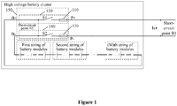
- the overcurrent protection circuit includes a first fusing module 110 and a second fusing module 120.
- the first fusing module 110 is arranged in a positive branch 130 of a switch box 150 of the high voltage battery cluster, and the second fusing module 120 is arranged in a negative branch 140 of the switch box 150 of the high voltage battery cluster.
- a withstand current-time curve of the first fusing module 110 is different from a withstand current-time curve of the second fusing module 120. That is, a duration that the first fusing module 110 can withstand a withstand current is different from a duration that the second fusing module 120 can withstand the same withstand current. Therefore, when a overcurrent fault occurs in the high voltage battery cluster, one of the first fusing module 110 and the second fusing module 120 is fused to cause an open circuit in the high voltage battery cluster prior to another of the first fusing module 110 and the second fusing module 120, thereby protecting the high voltage battery cluster from being broken by a large current.
- the present disclosure when the short-circuit fault occurs in the high voltage battery cluster, only one fuse module is fused to disconnect the high voltage battery cluster from the circuit, such that a superposition of current change rates in the conventional technology caused when two fuses are fused simultaneously can be avoided.
- the current change rate in the circuit is lower than that in the conventional technology caused in a case that the two fuses are fused simultaneously during the whole disconnecting process, thereby reducing a current impulse and a voltage impulse generated in the circuit, thus solving the problem in the conventional technology.
- a circuit structure of the high voltage battery cluster before two fuses or two fusing modules are fused may be simplified as shown in Figure 2 .
- F1 and F2 represent two fuses in the conventional technology and represent two fusing modules in the present disclosure.
- L present L1+L2+L3+L4+L5
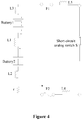
- L1 represents a parasitic inductance of a series line between battery modules in the high voltage battery cluster
- L2 represents a parasitic inductance of a connection line between a positive electrode of a battery module branch and a positive input terminal B+ of the switch box 150 in the high voltage battery cluster
- L3 represents a parasitic inductance of a connection line between a negative electrode of the battery module branch and a negative input terminal B- of the switch box 150 in the high voltage battery cluster
- L4 and L5 respectively represent parasitic inductances of positive and negative leads by which the high voltage battery cluster is respectively connected to a battery collection panel (BCP) and a power conversion system (PCS).
- BCP battery collection panel
- PCS power conversion system
- the short-circuit fault occurs in the high voltage battery cluster
- in a process from a time when the short-circuit fault occurs in the high voltage battery cluster to a time when one of the two fusing modules is fused since a resistance r of the circuit is reduced, a terminal voltage of the high voltage battery cluster is reduced, and a short-circuit current I s is increased rapidly.
- Changing curves of the short-circuit current I s and a reverse voltage U during this process are as shown in a process A in Figure 5 .
- the overcurrent protection circuit of a high voltage battery cluster in the embodiment, the current impulse and the voltage impulse generated in the circuit can be reduced.
- the time period during which the drawn arc is formed mainly depends on material characteristics and a fusing mechanism of the selected fuses.
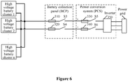
- the battery collection panel BCP includes a first fuse 310, a second fuse 320, a first direct current switch S3 and a second direct current switch S4.
- the first fuse 310 is connected in series with the first direct current switch S3 to form a branch, one terminal of the branch serves as a positive input terminal of the battery collection panel BCP, and another terminal of the branch serves as a positive output terminal of the battery collection panel BCP.
- the second fuse 320 is connected in series with the second direct current switch S4 to form a branch, one terminal of the branch serves as a negative input terminal of the battery collection panel BCP, and another end of the branch serves as a negative output terminal of the battery collection panel BCP.
- the power conversion system PCS includes a third fuse 330, a fourth fuse 340, a third direct current switch S5, a fourth direct current switch S6 and an inverter 350.
- the third fuse 330 is connected in series with the third direct current switch S5 to form a branch, one terminal of the branch serves as a positive input terminal of the power conversion system PCS, and another terminal of the branch is connected to a positive input terminal of the inverter 350.
- the fourth fuse 340 is connected in series with the fourth direct current switch S6 to form a branch, one terminal of the branch serves as a negative input terminal of the power conversion system PCS, and another terminal of the branch is connected to a negative input terminal of the inverter 350.
- a first output terminal of the inverter 350 serves as a first output terminal of the power conversion system PCS and is connected to a first input terminal of a power grid
- a second output terminal of the inverter 350 serves as a second output terminal of the power conversion system PCS and is connected to a second input terminal of the power grid
- a third output terminal of the inverter 350 serves as a third output terminal of the power conversion system PCS and is connected to a third input terminal of the power grid.
- a fuse operating high-sensitively is used as one of the first fusing module 110 and the second fusing module 120, to control the maximum short-circuit current I max to be in a small range.
- a fuse operating high-sensitively which has a proper time period during which a drawn arc is formed, is required to be used.
- the fuse operating high-sensitively is fused to cause an open circuit in the high voltage battery cluster prior to another fusing module.
- a fuse with both an overload breaking capacity and a short-circuit breaking capacity is used as another one of the first fusing module 110 and the second fusing module 120.
- the fuse with an overload breaking capacity and a short-circuit breaking capacity is fused to cause an open circuit in the high voltage battery cluster prior to another fuse.
- the fuse operating high-sensitively may be an AR fast fusing fuse
- the fuse with an overload breaking capacity and a short-circuit breaking capacity may be a gPV slow fusing fuse.
- a withstand current-time curve of the first fusing module 110 has an intersection point with a withstand current-time curve of the second fusing module 120, as shown in Figure 7 or Figure 8 .
- the withstand current-time curve of the first fusing module 110 and the withstand current-time curve of the second fusing module 120 are as shown in Figure 7 .
- the first fusing module 110 is fused to cause an open circuit in the high voltage battery cluster prior to the second fusing module 120
- the second fusing module 120 is fused to cause an open circuit in the high voltage battery cluster prior to the first fusing module 110.
- the withstand current-time curve of the first fusing module 110 and the withstand current-time curve of the second fusing module 120 are as shown in Figure 8 .
- the second fusing module 120 is fused to cause an open circuit in the high voltage battery cluster prior to the first fusing module 110
- the first fusing module 110 is fused to cause an open circuit in the high voltage battery cluster prior to the second fusing module 120.
- fusing curves of the first fusing module 110 and the second fusing module 120 should be below the withstand current-time curve of the direct current switch. That is, under the same withstanding current, both fusing duration of the first fusing module 110 and fusing duration of the second fusing module 120 are less than fusing duration of the direct current switch in the switch box 150 of the high voltage battery cluster, as shown in Figure 7 or Figure 8 .
- the first fusing module 110 or the second fusing module 120 is fused to disconnect the high voltage battery cluster from the circuit prior to the direct current switch, thereby ensuring an operation security of the direct current switch in the switch box 150 of the high voltage battery cluster.
- the following four arrangements of the first fusing module 110 and the second fusing module 120 are provided.
- a first arrangement is as shown in Figure 1 , where the first fusing module 110 is arranged between a direct current switch S1 in a positive branch 130 and an output terminal of the positive branch 130, and the second fusing module 120 is arranged between a direct current switch S2 in a negative branch 140 and an output terminal of the negative branch 140.
- a second arrangement is as shown in Figure 9a , where the first fusing module 110 is arranged between the direct current switch S1 in the positive branch 130 and the input terminal of the positive branch, and the second fusing module 120 is arranged between the direct current switch S2 in the negative branch 140 and the input terminal of the negative branch 140.
- a third arrangement is as shown in Figure 9b , where the first fusing module 110 is arranged between the direct current switch S1 in the positive branch 130 and an output terminal of the positive branch 130, and the second fusing module 120 is arranged between the direct current switch S2 in the negative branch 140 and the input terminal of the negative branch 140.
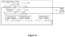
- a fourth arrangement is as shown in Figure 9c , where the first fusing module 110 is arranged between the direct current switch S1 in the positive branch 130 and the input terminal of the positive branch 130, and the second fusing module 120 is arranged between the direct current switch S2 in the negative branch 140 and the output terminal of the negative branch 140.
- the three arrangement and the fourth arrangement can be used to ensure electrical safety of the high voltage battery cluster, such that the high voltage battery cluster can be avoided from being broken due to a large short-circuit current I s as well as the large current impulse and the larger voltage impulse caused during the time period in which the fuses are fused.
- anyone of the four arrangements of the first fuse 110 and the second fuse 120 in the embodiment can be used to ensure electrical safety of the high voltage battery cluster in a case that the short-circuit fault occurs in the high voltage battery cluster, such that the high voltage battery cluster can be avoided from being broken due to a large short-circuit current I s as well as a large current impulse and a large voltage impulse caused during the time period in which the fuses are fused.
- an overcurrent protection circuit of a high voltage battery cluster is provided. Based on any one of above embodiments, the overcurrent protection circuit further includes an RCD snubber circuit 210, as shown in Figure 10 or Figure 11 (the switch box 150 is not shown in Figure 10 and Figure 11 ).
- An input terminal of the RCD snubber circuit 210 is connected to a positive input terminal B+ of the switch box 150 in the high voltage battery cluster, and an output terminal of the RCD snubber circuit 210 is connected to a negative input terminal B- (as shown in Figure 10 ) or a positive output terminal P+ (as shown in Figure 11 ) of the switch box 150 in the high voltage battery cluster.
- the RCD snubber circuit 210 may further reduce a reverse voltage U generated during the fusing process of the fuse, to reduce a peak value U max of the reverse voltage U, so as to reduce a current impulse and a voltage impulse generated in a circuit.
- the RCD snubber circuit 210 includes a resistor R, a capacitor C and a diode D.
- a terminal of the capacitor C serves as an output terminal of the RCD snubber circuit 210
- another terminal of the capacitor C is connected to a terminal of the resistor R and a negative electrode of the diode D
- another terminal of the resistor R is connected to a positive electrode of the diode D, where a connection point of the another terminal of the resistor R and the positive electrode of the diode D serves as an input terminal of the RCD snubber circuit 210.
- a switch box of a high voltage battery cluster is further provided, as shown in Figure 1 , Figure 9a , Figure 9b or Figure 9c .
- the switch box includes: a positive branch 130, a negative branch 140 and the overcurrent protection circuit of a high voltage battery cluster described in any one of above embodiments.
- the positive branch 130 is arranged with a direct current switch S1
- the negative branch 140 is arranged with a direct current switch S2.
- An input terminal of the positive branch 130 serves as a positive input terminal B+ of the switch box 150, and an output terminal of the positive branch 130 serves as a positive output terminal P+ of the switch box 150.
- An input terminal of the negative branch 140 serves as a negative input terminal B- of the switch box 150, and an output terminal of the negative branch 140 serves as a negative output terminal P- of the switch box 150.
- the RCD snubber circuit 210 in the overcurrent protection circuit of a high voltage battery cluster may be arranged in the switch box 150, facilitating an installation of the high voltage battery cluster.
- the RCD snubber circuit 210 may also be arranged outside the switch box 150, facilitating a disassembly of the RCD snubber circuit 210, and it may be determined whether to arrange the RCD snubber circuit 210 as needed.
- One of two arrangements of the RCD snubber circuit 210 may be selected depending on actual needs, which is not limited herein.
- a high voltage battery cluster is further provided, as shown in Figure 1 , Figure 9a , Figure 9b or Figure 9c .
- the high voltage battery cluster includes N battery modules (a first string of battery modules, a second string of battery modules ... and a (m)th string of battery modules) and the switch box 150 of a high voltage battery cluster described in the above embodiment.
- the N battery modules are sequentially connected in series to form a battery module branch.
- a positive electrode of the battery module branch is connected to the positive input terminal B+ of the switch box 150, and a negative electrode of the battery module branch is connected to the negative input terminal B- of the switch box 150.
- the positive output terminal P+ of the switch box 150 serves as a positive electrode of the high voltage battery cluster and is connected to a positive electrode of a circuit.
- the negative output terminal P- of the switch box 150 serves as a negative electrode of the high voltage battery cluster and is connected to a negative electrode of the circuit.
Landscapes
- Engineering & Computer Science (AREA)
- Power Engineering (AREA)
- Life Sciences & Earth Sciences (AREA)
- Sustainable Development (AREA)
- Sustainable Energy (AREA)
- Transportation (AREA)
- Mechanical Engineering (AREA)
- Charge And Discharge Circuits For Batteries Or The Like (AREA)
- Protection Of Static Devices (AREA)
- Emergency Protection Circuit Devices (AREA)
- Fuses (AREA)
Abstract
Description
- The present application claims priority to
Chinese Patent Application No. 201910609878.8, titled "HIGH VOLTAGE BATTERY CLUSTER, AND OVERCURRENT PROTECTION CIRCUIT AND SWITCH BOX THEREOF" filed on July 8, 2019 - The present disclosure relates to the field of power electronic technology, and in particular to a high voltage battery cluster, and an overcurrent protection circuit and a switch box of the high voltage battery cluster.
- At present, the electrochemical energy storage is widely developed in electric power systems. A capacity of the electrochemical energy storage in a typical application reaches MWh level for a single container, a port voltage of a single battery pack reaches 1000V, and even 1500V, and a charging/discharging current of the single battery pack reaches several hundred amperes. Therefore, in an operating environment under a high-voltage and large-current, a serious circuit safety problem may be caused in a case that an overcurrent fault, such as a short-circuit fault or an overload fault, occurs in a circuit.
- In order to avoid the serious circuit safety problem caused due to the overcurrent fault occurring in the circuit, in the conventional technology, each of a positive branch and a negative branch of a high voltage battery cluster is generally arranged with a fuse, to ensure that the high voltage battery cluster is disconnected from the circuit when the overcurrent fault occurs in the circuit.
- However, with above method, two fuses are both fused when the overcurrent fault occurs in the circuit, and a drawn arc thus generated may cause a large current change rate. In addition, a large voltage change rate is caused under an action of a parasitic inductance of the circuit, which may cause a large reverse voltage across two ends of the high voltage battery cluster. A peak value of the reverse voltage may be 2 to 5 times of a rated voltage of the high voltage battery cluster, directly affecting electrical safety of the high voltage battery cluster severely.
- In view of this, a high voltage battery cluster, and an overcurrent protection circuit and a switch box of the high voltage battery cluster are provided according to the present disclosure, to reduce a current impulse and a voltage impulse in the conventional technology, which are caused in a circuit due to that two fuses are both fused.
- To achieve above object, the following technical solutions are provided according to embodiments of the present disclosure.
- According to a first aspect of the present disclosure, an overcurrent protection circuit of a high voltage battery cluster is provided. The overcurrent protection circuit includes a first fusing module and a second fusing module. The first fusing module is arranged in a positive branch of a switch box of the high voltage battery cluster. The second fusing module is arranged in a negative branch of the switch box of the high voltage battery cluster. A withstand current-time curve of the first fusing module is different from a withstand current-time curve of the second fusing module.
- In an embodiment, the first fusing module is arranged between a direct current switch in the positive branch and an output terminal of the positive branch, and the second fusing module is arranged between a direct current switch in the negative branch and an input terminal of the negative branch. Alternatively, the first fusing module is arranged between the direct current switch in the positive branch and an input terminal of the positive branch, and the second fusing module is arranged between the direct current switch in the negative branch and an output terminal of the negative branch.
- In an embodiment, the first fusing module is arranged between a direct current switch in the positive branch and an output terminal of the positive branch, and the second fusing module is arranged between a direct current switch in the negative branch and an output terminal of the negative branch. Alternatively, the first fusing module is arranged between the direct current switch in the positive branch and an input terminal of the positive branch, and the second fusing module is arranged between the direct current switch in the negative branch and an input terminal of the negative branch.
- In an embodiment, one of the first fusing module and the second fusing module is a fuse operating high-sensitively.
- In an embodiment, another of the first fusing module and the second fusing module is a fuse with both an overload breaking capacity and a short-circuit breaking capacity.
- In an embodiment, under the same withstanding current, fusing duration of the first fusing module and fusing duration of the second fusing module are less than fusing duration of a direct current switch in the switch box of the high voltage battery cluster.
- In an embodiment, the withstand current-time curve of the first fusing module has an intersection with the withstand current-time curve of the second fusing module.
- In an embodiment, the overcurrent protection circuit further includes an RCD snubber circuit. An input terminal of the RCD snubber circuit is connected to a positive input terminal of the switch box, and an output terminal of the RCD snubber circuit is connected to a negative input terminal or a positive output terminal of the switch box.
- In an embodiment, the RCD snubber circuit includes a resistor, a capacitor and a diode. A terminal of the resistor is connected to a positive electrode of the diode, and a connection point between the terminal of the resistor and the positive electrode of the diode serves as an input terminal of the RCD snubber circuit, another terminal of the resistor and a negative electrode of the diode are connected to a terminal of the capacitor, and another terminal of the capacitor serves as an output terminal of the RCD snubber circuit.
- According to a second aspect of the present disclosure, a switch box of a high voltage battery cluster is further provided. The switch box includes a positive branch, a negative branch and any one of the overcurrent protection circuit of a high voltage battery clusters described above. Each of the positive branch and the negative branch is arranged with a direct current switch. An input terminal of the positive branch serves as a positive input terminal of the switch box, and an output terminal of the positive branch serves as a positive output terminal of the switch box. An input terminal of the negative branch serves as a negative input terminal of the switch box, and an output terminal of the negative branch serves as a negative output terminal of the switch box.
- According to a third aspect of the present disclosure, a high voltage battery cluster is further provided. The high voltage battery cluster includes N battery modules and the switch box described above. The N battery modules are sequentially connected in series to form a series branch, where a positive electrode of the series branch is connected to the positive input terminal of the switch box, and a negative electrode of the series branch is connected to the negative input terminal of the switch box. The positive output terminal of the switch box serves as a positive electrode of the high voltage battery cluster, and the negative output terminal of the switch box serves as a negative electrode of the high voltage battery cluster.
- The overcurrent protection circuit of a high voltage battery cluster according to the present disclosure includes a first fusing module and a second fusing module. Since a withstand current-time curve of the first fusing module is different from a withstand current-time curve of the second fusing module, in a case that an overcurrent fault occurs in a high voltage battery cluster, one fusing module can cause an open circuit in the high voltage battery cluster prior to another fusing module, thereby preventing the high voltage battery cluster from being broken by a large current when the overcurrent fault occurs in the high voltage battery cluster, thus ensuring an electrical safety of the high voltage battery cluster. In addition, compared with the conventional technology, according to the present disclosure, when the overcurrent fault occurs in the high voltage battery cluster, only one fuse module is fused to disconnect the high voltage battery cluster from the circuit, such that a superposition of current change rates in the conventional technology caused when two fuses are fused simultaneously can be avoided. In this way, during the whole disconnecting process, the current change rate in the circuit in the present disclosure is lower than that caused when two fuses are fused simultaneously in the conventional technology, thereby reducing a current impulse and a voltage impulse generated in the circuit, thus solving the problem in the conventional technology.
-
-
Figure 1 is a schematic diagram of a high voltage battery cluster according to an embodiment of the present disclosure; -
Figure 2 is a simplified schematic diagram of a circuit of a high voltage battery cluster according to the conventional technology and an embodiment of the present disclosure before two fuses or two fusing modules are fused when a short-circuit fault occurs in the high voltage battery cluster; -
Figure 3 is a simplified schematic diagram of a circuit of a high voltage battery cluster according to the conventional technology after two fuses are both fused when a short-circuit fault occurs in the high voltage battery cluster; -
Figure 4 is a simplified schematic diagram of a circuit of a high voltage battery cluster according to an embodiment of the present disclosure after one of two fuses is fused when a short-circuit fault occurs in the high voltage battery cluster; -
Figure 5 is a schematic diagram of a reverse voltage and a short-circuit current at two ends of a high voltage battery cluster; -
Figure 6 is a schematic diagram of a connection in a case that a high voltage battery cluster is applied; -
Figure 7 andFigure 8 are graphs respectively showing withstand current-time curves of afirst fusing module 110, asecond fusing module 120 and a direct current switch; -
Figure 9a, Figure 9b andFigure 9c are schematic diagrams of three high voltage battery clusters according to another embodiment of the present disclosure; -
Figure 10 is a simplified schematic diagram of a circuit of a high voltage battery cluster with an RCD snubber circuit according to another embodiment of the present disclosure; and -
Figure 11 is a simplified schematic diagram of a circuit of a high voltage battery cluster with an RCD snubber circuit according to another embodiment of the present disclosure. - In order to further understand the present disclosure, preferred technical solutions of the present disclosure are described below in conjunction with embodiments. However, it should be understood that these descriptions are only used for further describing features and advantages of the present disclosure, rather than limiting the claims of the present disclosure.
- With the method in the conventional technology, in a case that an overcurrent fault such as a short-circuit fault or an overload fault occurs in a high voltage battery cluster, since two fuses are fused almost simultaneously, a drawn arc generated by the two fuses may results in a superposition of current change rates in a circuit, which may cause a large current change rate in the circuit and further cause a large voltage change rate in the circuit. In this case, a large current impulse and a large voltage impulse may be caused to a positive electrode and a negative electrode of the high voltage battery cluster in the circuit, resulting in a severe effect on electrical safety of the high voltage battery cluster.
- In order to solve the problem in the conventional technology that the large current impulse and the large voltage impulse are generated in the circuit when fuses are fused, an overcurrent protection circuit of a high voltage battery cluster is provided according to an embodiment of the present disclosure. As shown in
Figure 1 , the overcurrent protection circuit includes afirst fusing module 110 and asecond fusing module 120. - The
first fusing module 110 is arranged in apositive branch 130 of aswitch box 150 of the high voltage battery cluster, and thesecond fusing module 120 is arranged in anegative branch 140 of theswitch box 150 of the high voltage battery cluster. - A withstand current-time curve of the
first fusing module 110 is different from a withstand current-time curve of thesecond fusing module 120. That is, a duration that thefirst fusing module 110 can withstand a withstand current is different from a duration that thesecond fusing module 120 can withstand the same withstand current. Therefore, when a overcurrent fault occurs in the high voltage battery cluster, one of thefirst fusing module 110 and thesecond fusing module 120 is fused to cause an open circuit in the high voltage battery cluster prior to another of thefirst fusing module 110 and thesecond fusing module 120, thereby protecting the high voltage battery cluster from being broken by a large current. - Compared with the conventional technology, according to the present disclosure, when the short-circuit fault occurs in the high voltage battery cluster, only one fuse module is fused to disconnect the high voltage battery cluster from the circuit, such that a superposition of current change rates in the conventional technology caused when two fuses are fused simultaneously can be avoided. In this way, the current change rate in the circuit is lower than that in the conventional technology caused in a case that the two fuses are fused simultaneously during the whole disconnecting process, thereby reducing a current impulse and a voltage impulse generated in the circuit, thus solving the problem in the conventional technology.
- In the conventional technology and the present disclosure, in a case that the short-circuit fault occurs in the high voltage battery cluster, a circuit structure of the high voltage battery cluster before two fuses or two fusing modules are fused may be simplified as shown in
Figure 2 . InFigure 2 , F1 and F2 represent two fuses in the conventional technology and represent two fusing modules in the present disclosure. - In the conventional technology, in a case that the short-circuit fault occurs in the high voltage battery cluster, a circuit structure of the high voltage battery cluster after two fuses are fused may be simplified as shown in
Figure 3 , and a circuit inductance formed in this case may be expressed as Lconventional =L1+L2+L3. In the present embodiment, in a case that the short-circuit fault occurs in the high voltage battery cluster, a circuit structure of the high voltage battery cluster after one of the two fusing modules is fused may be simplified as shown inFigure 4 , and a circuit inductance formed in this case may be expressed as Lpresent =L1+L2+L3+L4+L5, which is greater than the circuit inductance Lconventional formed in the conventional technology and has a better performance in impeding the change of a current in the circuit. In this way, the current in the circuit changes slowly and a fusing duration is prolonged, such that the current change rate di/dt is reduced, thereby reducing the current impulse and the voltage impulse generated in the circuit. - In above expressions, L1 represents a parasitic inductance of a series line between battery modules in the high voltage battery cluster, L2 represents a parasitic inductance of a connection line between a positive electrode of a battery module branch and a positive input terminal B+ of the
switch box 150 in the high voltage battery cluster, L3 represents a parasitic inductance of a connection line between a negative electrode of the battery module branch and a negative input terminal B- of theswitch box 150 in the high voltage battery cluster, and L4 and L5 respectively represent parasitic inductances of positive and negative leads by which the high voltage battery cluster is respectively connected to a battery collection panel (BCP) and a power conversion system (PCS). - In a case that an overload fault occurs in the high voltage battery cluster, a process is the same as the above process, which is not described in detail herein.
- Moreover, in the embodiment, in a case that the short-circuit fault occurs in the high voltage battery cluster, in a process from a time when the short-circuit fault occurs in the high voltage battery cluster to a time when one of the two fusing modules is fused, since a resistance r of the circuit is reduced, a terminal voltage of the high voltage battery cluster is reduced, and a short-circuit current Is is increased rapidly. Changing curves of the short-circuit current Is and a reverse voltage U during this process are as shown in a process A in
Figure 5 . In addition, with the overcurrent protection circuit of a high voltage battery cluster in the embodiment, the current impulse and the voltage impulse generated in the circuit can be reduced. However, during a process from a time when one of the two fusing modules is to fuse to a time when the one of the two fusing modules is fused, since the high voltage battery cluster is connected to the battery collection panel BCP and the power conversion system PCS respectively by long positive and negative leads (as shown inFigure 6 ) and the battery modules of the high voltage battery cluster are connected in series by series lines, an inductance L generated in the circuit is large, such that a large current change rate di/dt may be caused by the fusing module during a time period during which a drawn arc is formed, which generally lasts tens of microseconds to hundreds of microseconds. In this case, a large reverse voltage may be generated, which is expressed as U=L*di/dt, where changing curves of the short-circuit current Is and the reverse voltage U are as shown in a process B inFigure 5 . - The time period during which the drawn arc is formed mainly depends on material characteristics and a fusing mechanism of the selected fuses.
- Specifically, the battery collection panel BCP includes a
first fuse 310, asecond fuse 320, a first direct current switch S3 and a second direct current switch S4. Thefirst fuse 310 is connected in series with the first direct current switch S3 to form a branch, one terminal of the branch serves as a positive input terminal of the battery collection panel BCP, and another terminal of the branch serves as a positive output terminal of the battery collection panel BCP. Thesecond fuse 320 is connected in series with the second direct current switch S4 to form a branch, one terminal of the branch serves as a negative input terminal of the battery collection panel BCP, and another end of the branch serves as a negative output terminal of the battery collection panel BCP. - Specifically, the power conversion system PCS includes a
third fuse 330, afourth fuse 340, a third direct current switch S5, a fourth direct current switch S6 and aninverter 350. Thethird fuse 330 is connected in series with the third direct current switch S5 to form a branch, one terminal of the branch serves as a positive input terminal of the power conversion system PCS, and another terminal of the branch is connected to a positive input terminal of theinverter 350. Thefourth fuse 340 is connected in series with the fourth direct current switch S6 to form a branch, one terminal of the branch serves as a negative input terminal of the power conversion system PCS, and another terminal of the branch is connected to a negative input terminal of theinverter 350. A first output terminal of theinverter 350 serves as a first output terminal of the power conversion system PCS and is connected to a first input terminal of a power grid, a second output terminal of theinverter 350 serves as a second output terminal of the power conversion system PCS and is connected to a second input terminal of the power grid, and a third output terminal of theinverter 350 serves as a third output terminal of the power conversion system PCS and is connected to a third input terminal of the power grid. - In an embodiment, in a case that the short-circuit fault occurs in the high voltage battery cluster, a maximum short-circuit current Imax impose a large influence on safety and life of a battery, and even an electrical hazard such as thermal runaway may be caused to the battery in a severe case. Therefore, a fuse operating high-sensitively is used as one of the
first fusing module 110 and thesecond fusing module 120, to control the maximum short-circuit current Imax to be in a small range. In addition, in order to control the current change rate di/dt to be in a small range and to reduce a peak value Umax of the reverse voltage U, a fuse operating high-sensitively, which has a proper time period during which a drawn arc is formed, is required to be used. - It is to be noted that, when the short-circuit fault occurs in the high voltage battery cluster, the fuse operating high-sensitively is fused to cause an open circuit in the high voltage battery cluster prior to another fusing module.
- In an embodiment, in order to ensure electrical safety of a high voltage battery cluster while meeting requirements on current flow capacity and operation sensitivity of the high voltage battery cluster when an overload fault occurs in the high voltage battery cluster, a fuse with both an overload breaking capacity and a short-circuit breaking capacity is used as another one of the
first fusing module 110 and thesecond fusing module 120. - It is to be noted that, when the overload fault occurs in the high voltage battery cluster, the fuse with an overload breaking capacity and a short-circuit breaking capacity is fused to cause an open circuit in the high voltage battery cluster prior to another fuse.
- In an embodiment, the fuse operating high-sensitively may be an AR fast fusing fuse, and the fuse with an overload breaking capacity and a short-circuit breaking capacity may be a gPV slow fusing fuse.
- Moreover, in an actual application, a withstand current-time curve of the
first fusing module 110 has an intersection point with a withstand current-time curve of thesecond fusing module 120, as shown inFigure 7 orFigure 8 . - In a case that the
first fusing module 110 is the fuse operating high-sensitively, and thesecond fusing module 120 is the fuse with an overload breaking capacity and a short-circuit breaking capacity, the withstand current-time curve of thefirst fusing module 110 and the withstand current-time curve of thesecond fusing module 120 are as shown inFigure 7 . In a case that the short-circuit fault occurs in the high voltage battery cluster, thefirst fusing module 110 is fused to cause an open circuit in the high voltage battery cluster prior to thesecond fusing module 120, and in a case that the overload fault occurs in the high voltage battery cluster, thesecond fusing module 120 is fused to cause an open circuit in the high voltage battery cluster prior to thefirst fusing module 110. - In a case that the
first fusing module 110 is the fuse with an overload breaking capacity and a short-circuit breaking capacity and thesecond fusing module 120 is the fuse operating high-sensitively, the withstand current-time curve of thefirst fusing module 110 and the withstand current-time curve of thesecond fusing module 120 are as shown inFigure 8 . In a case that the short-circuit fault occurs in the high voltage battery cluster, thesecond fusing module 120 is fused to cause an open circuit in the high voltage battery cluster prior to thefirst fusing module 110, and in a case that the overload fault occurs in the high voltage battery cluster, thefirst fusing module 110 is fused to cause an open circuit in the high voltage battery cluster prior to thesecond fusing module 120. - In addition, fusing curves of the
first fusing module 110 and thesecond fusing module 120 should be below the withstand current-time curve of the direct current switch. That is, under the same withstanding current, both fusing duration of thefirst fusing module 110 and fusing duration of thesecond fusing module 120 are less than fusing duration of the direct current switch in theswitch box 150 of the high voltage battery cluster, as shown inFigure 7 orFigure 8 . Before the direct current switch is broken, thefirst fusing module 110 or thesecond fusing module 120 is fused to disconnect the high voltage battery cluster from the circuit prior to the direct current switch, thereby ensuring an operation security of the direct current switch in theswitch box 150 of the high voltage battery cluster. - In another embodiment of the present disclosure, the following four arrangements of the
first fusing module 110 and thesecond fusing module 120 are provided. - A first arrangement is as shown in
Figure 1 , where thefirst fusing module 110 is arranged between a direct current switch S1 in apositive branch 130 and an output terminal of thepositive branch 130, and thesecond fusing module 120 is arranged between a direct current switch S2 in anegative branch 140 and an output terminal of thenegative branch 140. - A second arrangement is as shown in
Figure 9a , where thefirst fusing module 110 is arranged between the direct current switch S1 in thepositive branch 130 and the input terminal of the positive branch, and thesecond fusing module 120 is arranged between the direct current switch S2 in thenegative branch 140 and the input terminal of thenegative branch 140. - A third arrangement is as shown in
Figure 9b , where thefirst fusing module 110 is arranged between the direct current switch S1 in thepositive branch 130 and an output terminal of thepositive branch 130, and thesecond fusing module 120 is arranged between the direct current switch S2 in thenegative branch 140 and the input terminal of thenegative branch 140. - A fourth arrangement is as shown in
Figure 9c , where thefirst fusing module 110 is arranged between the direct current switch S1 in thepositive branch 130 and the input terminal of thepositive branch 130, and thesecond fusing module 120 is arranged between the direct current switch S2 in thenegative branch 140 and the output terminal of thenegative branch 140. - It is to be noted that one of the four arrangements may selected as needed, which is not limited herein.
- It is to be noted that, in a case that a short-circuit fault occurs outside the high voltage battery cluster, that is, in a case that a short-circuit fault occurs at a short-circuit point B1, anyone of the four arrangements of the
first fuse 110 and thesecond fuse 120 in the embodiment can be used to ensure electrical safety of the high voltage battery cluster, such that the high voltage battery cluster can be avoided from being broken due to a large short-circuit current Is as well as a large current impulse and a large voltage impulse caused during the time period in which the fuses are fused. In addition, in a case that a short-circuit fault occurs in the high voltage battery cluster, that is, in a case that a short-circuit fault occurs at a short-circuit point B2, anyone of the second arrangement, the three arrangement and the fourth arrangement can be used to ensure electrical safety of the high voltage battery cluster, such that the high voltage battery cluster can be avoided from being broken due to a large short-circuit current Is as well as the large current impulse and the larger voltage impulse caused during the time period in which the fuses are fused. In addition, anyone of the four arrangements of thefirst fuse 110 and thesecond fuse 120 in the embodiment can be used to ensure electrical safety of the high voltage battery cluster in a case that the short-circuit fault occurs in the high voltage battery cluster, such that the high voltage battery cluster can be avoided from being broken due to a large short-circuit current Is as well as a large current impulse and a large voltage impulse caused during the time period in which the fuses are fused. - Other structures and operation principles are the same as that in the above embodiments, which are not described in detail herein.
- In another embodiment of the present disclosure, an overcurrent protection circuit of a high voltage battery cluster is provided. Based on any one of above embodiments, the overcurrent protection circuit further includes an
RCD snubber circuit 210, as shown inFigure 10 orFigure 11 (theswitch box 150 is not shown inFigure 10 andFigure 11 ). - An input terminal of the
RCD snubber circuit 210 is connected to a positive input terminal B+ of theswitch box 150 in the high voltage battery cluster, and an output terminal of theRCD snubber circuit 210 is connected to a negative input terminal B- (as shown inFigure 10 ) or a positive output terminal P+ (as shown inFigure 11 ) of theswitch box 150 in the high voltage battery cluster. - It is to be noted that the
RCD snubber circuit 210 may further reduce a reverse voltage U generated during the fusing process of the fuse, to reduce a peak value Umax of the reverse voltage U, so as to reduce a current impulse and a voltage impulse generated in a circuit. - Specifically, the
RCD snubber circuit 210 includes a resistor R, a capacitor C and a diode D. A terminal of the capacitor C serves as an output terminal of theRCD snubber circuit 210, another terminal of the capacitor C is connected to a terminal of the resistor R and a negative electrode of the diode D, and another terminal of the resistor R is connected to a positive electrode of the diode D, where a connection point of the another terminal of the resistor R and the positive electrode of the diode D serves as an input terminal of theRCD snubber circuit 210. - Other structures and operation principles are the same as that in the above embodiments, which are not described in detail herein.
- In another embodiment of the present disclosure, a switch box of a high voltage battery cluster is further provided, as shown in
Figure 1 ,Figure 9a ,Figure 9b orFigure 9c . The switch box includes: apositive branch 130, anegative branch 140 and the overcurrent protection circuit of a high voltage battery cluster described in any one of above embodiments. - The
positive branch 130 is arranged with a direct current switch S1, and thenegative branch 140 is arranged with a direct current switch S2. - An input terminal of the
positive branch 130 serves as a positive input terminal B+ of theswitch box 150, and an output terminal of thepositive branch 130 serves as a positive output terminal P+ of theswitch box 150. - An input terminal of the
negative branch 140 serves as a negative input terminal B- of theswitch box 150, and an output terminal of thenegative branch 140 serves as a negative output terminal P- of theswitch box 150. - It is to be noted that the
RCD snubber circuit 210 in the overcurrent protection circuit of a high voltage battery cluster may be arranged in theswitch box 150, facilitating an installation of the high voltage battery cluster. In addition, theRCD snubber circuit 210 may also be arranged outside theswitch box 150, facilitating a disassembly of theRCD snubber circuit 210, and it may be determined whether to arrange theRCD snubber circuit 210 as needed. One of two arrangements of theRCD snubber circuit 210 may be selected depending on actual needs, which is not limited herein. - Other structures and operation principles are the same as that in the above embodiments, which are not described in detail herein.
- In another embodiment of the present disclosure, a high voltage battery cluster is further provided, as shown in
Figure 1 ,Figure 9a ,Figure 9b orFigure 9c . The high voltage battery cluster includes N battery modules (a first string of battery modules, a second string of battery modules ... and a (m)th string of battery modules) and theswitch box 150 of a high voltage battery cluster described in the above embodiment. - The N battery modules are sequentially connected in series to form a battery module branch. A positive electrode of the battery module branch is connected to the positive input terminal B+ of the
switch box 150, and a negative electrode of the battery module branch is connected to the negative input terminal B- of theswitch box 150. - The positive output terminal P+ of the
switch box 150 serves as a positive electrode of the high voltage battery cluster and is connected to a positive electrode of a circuit. The negative output terminal P- of theswitch box 150 serves as a negative electrode of the high voltage battery cluster and is connected to a negative electrode of the circuit. - Other structures and operation principles are the same as that in the above embodiments, which are not described in detail herein.
- The embodiments in this specification are described in a progressive way, each of which emphasizes the differences from others, and the same or similar parts among the embodiments can be referred to each other.
- With the description of the embodiments disclosed above, those skilled in the art may implement or use technical solutions of the present disclosure. Numerous modifications to the embodiments are apparent to those skilled in the art, and the general principles defined herein may be implemented in other embodiments without departing from the spirit or scope of the present disclosure. Therefore, the present disclosure may not be limited to the embodiments described herein, but should comply with the widest scope consistent with the principles and novel features disclosed herein.
Claims (11)
- An overcurrent protection circuit of a high voltage battery cluster, comprising:a first fusing module arranged in a positive branch of a switch box of the high voltage battery cluster; anda second fusing module arranged in a negative branch of the switch box of the high voltage battery cluster, whereina withstand current-time curve of the first fusing module is different from a withstand current-time curve of the second fusing module.
- The overcurrent protection circuit according to claim 1, wherein the first fusing module is arranged between a direct current switch in the positive branch and an output terminal of the positive branch, and the second fusing module is arranged between a direct current switch in the negative branch and an input terminal of the negative branch; or
the first fusing module is arranged between the direct current switch in the positive branch and an input terminal of the positive branch, and the second fusing module is arranged between the direct current switch in the negative branch and an output terminal of the negative branch. - The overcurrent protection circuit according to claim 1, wherein the first fusing module is arranged between a direct current switch in the positive branch and an output terminal of the positive branch, and the second fusing module is arranged between a direct current switch in the negative branch and an output terminal of the negative branch; or
the first fusing module is arranged between the direct current switch in the positive branch and an input terminal of the positive branch, and the second fusing module is arranged between the direct current switch in the negative branch and an input terminal of the negative branch. - The overcurrent protection circuit according to claim 1, wherein one of the first fusing module and the second fusing module is a fuse operating high-sensitively.
- The overcurrent protection circuit according to claim 4, wherein another of the first fusing module and the second fusing module is a fuse with both an overload breaking capacity and a short-circuit breaking capacity.
- The overcurrent protection circuit according to claim 1, wherein under a same withstanding current, each of fusing duration of the first fusing module and fusing duration of the second fusing module is less than fusing duration of a direct current switch in the switch box of the high voltage battery cluster.
- The overcurrent protection circuit according to claim 6, wherein the withstand current-time curve of the first fusing module has an intersection point with the withstand current-time curve of the second fusing module.
- The overcurrent protection circuit according to any one of claim 1 to 7, further comprising:
an RCD snubber circuit, wherein an input terminal of the RCD snubber circuit is connected to a positive input terminal of the switch box, and an output terminal of the RCD snubber circuit is connected to a negative input terminal or a positive output terminal of the switch box. - The overcurrent protection circuit according to claim 8, wherein the RCD snubber circuit comprises: a resistor, a capacitor and a diode, whereina terminal of the resistor is connected to a positive electrode of the diode, and a connection point between the terminal of the resistor and the positive electrode of the diode serves as the input terminal of the RCD snubber circuit,another terminal of the resistor and a negative electrode of the diode are connected to a terminal of the capacitor, andanother terminal of the capacitor serves as the output terminal of the RCD snubber circuit.
- A switch box of a high voltage battery cluster, comprising: a positive branch, a negative branch and the overcurrent protection circuit of a high voltage battery cluster according to any one of claim 1 to 9, whereineach of the positive branch and the negative branch is arranged with a direct current switch,an input terminal of the positive branch serves as a positive input terminal of the switch box, and an output terminal of the positive branch serves as a positive output terminal of the switch box, andan input terminal of the negative branch serves as a negative input terminal of the switch box, and an output terminal of the negative branch serves as a negative output terminal of the switch box.
- A high voltage battery cluster, comprising: N battery modules, and the switch box according to claim 10, whereinthe N battery modules are sequentially connected in series to form a series branch, wherein a positive electrode of the series branch is connected to the positive input terminal of the switch box, and a negative electrode of the series branch is connected to the negative input terminal of the switch box,the positive output terminal of the switch box serves as a positive electrode of the high voltage battery cluster, andthe negative output terminal of the switch box serves as a negative electrode of the high voltage battery cluster.
Applications Claiming Priority (2)
| Application Number | Priority Date | Filing Date | Title |
|---|---|---|---|
| CN201910609878.8A CN110299744B (en) | 2019-07-08 | 2019-07-08 | High-voltage battery cluster and overcurrent protection circuit and switch box thereof |
| PCT/CN2019/128525 WO2021004027A1 (en) | 2019-07-08 | 2019-12-26 | High-voltage battery cluster and over-current protection circuit and switch box therefor |
Publications (2)
| Publication Number | Publication Date |
|---|---|
| EP3913763A1 true EP3913763A1 (en) | 2021-11-24 |
| EP3913763A4 EP3913763A4 (en) | 2022-12-14 |
Family
ID=68030619
Family Applications (1)
| Application Number | Title | Priority Date | Filing Date |
|---|---|---|---|
| EP19920623.6A Pending EP3913763A4 (en) | 2019-07-08 | 2019-12-26 | HIGH VOLTAGE BATTERY SET AND OVERCURRENT PROTECTION CIRCUIT AND ASSOCIATED SWITCH BOX |
Country Status (7)
| Country | Link |
|---|---|
| US (1) | US11942775B2 (en) |
| EP (1) | EP3913763A4 (en) |
| JP (1) | JP7374919B2 (en) |
| KR (1) | KR102541790B1 (en) |
| CN (1) | CN110299744B (en) |
| AU (1) | AU2019435043B2 (en) |
| WO (1) | WO2021004027A1 (en) |
Families Citing this family (13)
| Publication number | Priority date | Publication date | Assignee | Title |
|---|---|---|---|---|
| CN110299744B (en) * | 2019-07-08 | 2021-12-10 | 阳光电源股份有限公司 | High-voltage battery cluster and overcurrent protection circuit and switch box thereof |
| CN113036317A (en) * | 2021-03-02 | 2021-06-25 | 阳光电源股份有限公司 | A battery cluster and energy storage system |
| KR102652768B1 (en) * | 2021-03-29 | 2024-04-01 | 엘에스일렉트릭(주) | Bpu(battery protection unit) and method for controlling thereof |
| CN113300009A (en) * | 2021-05-21 | 2021-08-24 | 阳光电源股份有限公司 | Battery cluster and energy storage system |
| CN113328490B (en) * | 2021-05-27 | 2026-03-31 | 科华数据股份有限公司 | Power supply system |
| CN115833192A (en) * | 2021-09-16 | 2023-03-21 | 台达电子企业管理(上海)有限公司 | Energy storage system |
| CN113839402A (en) * | 2021-09-24 | 2021-12-24 | 远景能源有限公司 | An energy storage battery cluster and an energy storage system |
| CN115173372B (en) * | 2022-07-26 | 2024-09-03 | 广州小鹏汽车科技有限公司 | Short circuit protection circuit, power battery pack and vehicle |
| CN116207456A (en) * | 2023-01-03 | 2023-06-02 | 楚能新能源股份有限公司 | High-voltage overcurrent protection mechanism for battery |
| CN117293490A (en) * | 2023-10-30 | 2023-12-26 | 江苏天合储能有限公司 | Energy storage system and its fault monitoring method |
| CN117747374B (en) * | 2024-01-29 | 2024-10-29 | 北京广发电气有限公司 | Automatic change high-voltage fuse |
| CN118174236B (en) * | 2024-03-15 | 2025-03-14 | 武汉亿纬储能有限公司 | Energy storage system circuit protection method and energy storage system circuit |
| WO2025189605A1 (en) * | 2024-03-15 | 2025-09-18 | 武汉亿纬储能有限公司 | Energy storage system, and circuit protection method for energy storage system |
Family Cites Families (19)
| Publication number | Priority date | Publication date | Assignee | Title |
|---|---|---|---|---|
| GB2381393B (en) | 2001-10-26 | 2005-11-02 | Agco Gmbh & Co | Mobile high voltage network |
| JP2005285717A (en) * | 2004-03-31 | 2005-10-13 | Matsushita Electric Ind Co Ltd | Circuit protection device |
| DE102009007969B4 (en) * | 2009-02-06 | 2025-08-21 | Siemens Energy Global GmbH & Co. KG | Switchgear with short-circuit protection devices |
| CN102097796A (en) | 2010-12-30 | 2011-06-15 | 广东易事特电源股份有限公司 | The voltage spike absorption protection circuit of the power switch tube of the solar charge controller |
| CN102570389B (en) | 2012-02-20 | 2015-04-29 | 优利德科技(中国)有限公司 | A kind of protection method for high voltage misdetection of multimeter and multimeter |
| CN202839883U (en) * | 2012-09-28 | 2013-03-27 | 比亚迪股份有限公司 | Power battery pack |
| JP2014235997A (en) | 2013-06-05 | 2014-12-15 | パナソニックIpマネジメント株式会社 | Shut-off device and power conversion system |
| CN115095808A (en) | 2014-09-28 | 2022-09-23 | 嘉兴山蒲照明电器有限公司 | A LED straight tube light |
| CN104836191A (en) | 2014-11-05 | 2015-08-12 | 北汽福田汽车股份有限公司 | Method of selecting circuit fuses |
| CN204367903U (en) * | 2015-01-13 | 2015-06-03 | 安徽江淮汽车股份有限公司 | A kind of electrokinetic cell bag |
| JP2016144340A (en) * | 2015-02-03 | 2016-08-08 | 株式会社サムスン日本研究所 | Snubber circuit |
| US9882401B2 (en) | 2015-11-04 | 2018-01-30 | Powin Energy Corporation | Battery energy storage system |
| CN206442130U (en) * | 2016-12-05 | 2017-08-25 | 深圳无限能源科技有限公司 | Power battery charging protection device |
| DE102017106058A1 (en) | 2017-03-21 | 2018-09-27 | Dr. Ing. H.C. F. Porsche Aktiengesellschaft | Battery system and method of operation |
| KR102176100B1 (en) | 2017-05-23 | 2020-11-09 | 엘에스일렉트릭(주) | Power converting apparatus |
| CN107591829A (en) | 2017-09-25 | 2018-01-16 | 中天储能科技有限公司 | A kind of large-scale energy storage high direct voltage control system and its control method |
| CN108879027B (en) * | 2018-05-22 | 2021-08-17 | 宁德时代新能源科技股份有限公司 | Heating Systems and Power Switching Devices |
| CN110299744B (en) | 2019-07-08 | 2021-12-10 | 阳光电源股份有限公司 | High-voltage battery cluster and overcurrent protection circuit and switch box thereof |
| CN113036317A (en) * | 2021-03-02 | 2021-06-25 | 阳光电源股份有限公司 | A battery cluster and energy storage system |
-
2019
- 2019-07-08 CN CN201910609878.8A patent/CN110299744B/en active Active
- 2019-12-26 JP JP2020551316A patent/JP7374919B2/en active Active
- 2019-12-26 WO PCT/CN2019/128525 patent/WO2021004027A1/en not_active Ceased
- 2019-12-26 EP EP19920623.6A patent/EP3913763A4/en active Pending
- 2019-12-26 AU AU2019435043A patent/AU2019435043B2/en active Active
- 2019-12-26 US US17/040,501 patent/US11942775B2/en active Active
- 2019-12-26 KR KR1020207029535A patent/KR102541790B1/en active Active
Also Published As
| Publication number | Publication date |
|---|---|
| US20230107559A1 (en) | 2023-04-06 |
| AU2019435043A1 (en) | 2021-02-04 |
| CN110299744B (en) | 2021-12-10 |
| JP2021532707A (en) | 2021-11-25 |
| US11942775B2 (en) | 2024-03-26 |
| KR20210008334A (en) | 2021-01-21 |
| AU2019435043B2 (en) | 2021-11-04 |
| JP7374919B2 (en) | 2023-11-07 |
| EP3913763A4 (en) | 2022-12-14 |
| WO2021004027A1 (en) | 2021-01-14 |
| CN110299744A (en) | 2019-10-01 |
| KR102541790B1 (en) | 2023-06-12 |
Similar Documents
| Publication | Publication Date | Title |
|---|---|---|
| US11942775B2 (en) | High voltage battery cluster, and overcurrent protection circuit and switch box thereof | |
| JP6250153B2 (en) | High voltage direct current interrupting device and method | |
| RU2500062C2 (en) | High-speed switching device for high-power accumulator battery in isolated dc circuit | |
| EP3672008B1 (en) | Series compensator, and control method | |
| Li et al. | Frontiers of DC circuit breakers in HVDC and MVDC systems | |
| CN105305371B (en) | A High Voltage DC Circuit Breaker with Coupling Reactor | |
| KR20180103181A (en) | DC current interrupter and control method | |
| CN110970875A (en) | Combined current-limiting type direct current breaker for direct current power grid | |
| CN103646805B (en) | A kind of direct-current breaker topology | |
| KR20180096999A (en) | Fault current limiting for DC grid type and the method thereof | |
| CN112670961B (en) | Frequency converter bus short-circuit protection device and protection method | |
| CN106301307B (en) | A novel cascaded full-bridge high-voltage DC circuit breaker and its control method | |
| CN116231578A (en) | A multi-stage stepped protection system based on the DC side of the energy storage system | |
| CN110416980A (en) | A self-adaptive reclosing method for a combined DC circuit breaker | |
| JP6456575B1 (en) | DC circuit breaker | |
| CN113839402A (en) | An energy storage battery cluster and an energy storage system | |
| CN205160034U (en) | Take high voltage direct current circuit breaker of coupling reactance ware | |
| CN216017272U (en) | Circuit board and battery pack | |
| CN210693443U (en) | Short-circuit protection device for bus of frequency converter | |
| WO2025098110A1 (en) | Series-connected dc/dc short-circuit protection circuit and short-circuit protector | |
| CN216649233U (en) | Power electronic switch device for BESS system | |
| CN210224996U (en) | A UPS battery pack charging circuit protection device | |
| CN222750159U (en) | Protection circuit of energy storage system, battery pack and energy storage system | |
| CN223978423U (en) | A topology of a dual-bridge all-solid-state high-voltage DC circuit breaker | |
| CN217115607U (en) | Short-circuit protection device and direct current distribution system |
Legal Events
| Date | Code | Title | Description |
|---|---|---|---|
| STAA | Information on the status of an ep patent application or granted ep patent |
Free format text: STATUS: UNKNOWN |
|
| STAA | Information on the status of an ep patent application or granted ep patent |
Free format text: STATUS: THE INTERNATIONAL PUBLICATION HAS BEEN MADE |
|
| PUAI | Public reference made under article 153(3) epc to a published international application that has entered the european phase |
Free format text: ORIGINAL CODE: 0009012 |
|
| STAA | Information on the status of an ep patent application or granted ep patent |
Free format text: STATUS: REQUEST FOR EXAMINATION WAS MADE |
|
| 17P | Request for examination filed |
Effective date: 20200928 |
|
| AK | Designated contracting states |
Kind code of ref document: A1 Designated state(s): AL AT BE BG CH CY CZ DE DK EE ES FI FR GB GR HR HU IE IS IT LI LT LU LV MC MK MT NL NO PL PT RO RS SE SI SK SM TR |
|
| DAV | Request for validation of the european patent (deleted) | ||
| DAX | Request for extension of the european patent (deleted) | ||
| A4 | Supplementary search report drawn up and despatched |
Effective date: 20221115 |
|
| RIC1 | Information provided on ipc code assigned before grant |
Ipc: H02H 7/18 20060101ALI20221109BHEP Ipc: H02J 7/00 20060101AFI20221109BHEP |