EP3913744A1 - Antenna device and power feeding device - Google Patents
Antenna device and power feeding device Download PDFInfo
- Publication number
- EP3913744A1 EP3913744A1 EP19915858.5A EP19915858A EP3913744A1 EP 3913744 A1 EP3913744 A1 EP 3913744A1 EP 19915858 A EP19915858 A EP 19915858A EP 3913744 A1 EP3913744 A1 EP 3913744A1
- Authority
- EP
- European Patent Office
- Prior art keywords
- axis
- plane
- antenna
- unit configured
- phase
- Prior art date
- Legal status (The legal status is an assumption and is not a legal conclusion. Google has not performed a legal analysis and makes no representation as to the accuracy of the status listed.)
- Granted
Links
Images


Classifications
-
- H—ELECTRICITY
- H01—ELECTRIC ELEMENTS
- H01Q—ANTENNAS, i.e. RADIO AERIALS
- H01Q3/00—Arrangements for changing or varying the orientation or the shape of the directional pattern of the waves radiated from an antenna or antenna system
- H01Q3/26—Arrangements for changing or varying the orientation or the shape of the directional pattern of the waves radiated from an antenna or antenna system varying the relative phase or relative amplitude of energisation between two or more active radiating elements; varying the distribution of energy across a radiating aperture
- H01Q3/2676—Optically controlled phased array
-
- H—ELECTRICITY
- H01—ELECTRIC ELEMENTS
- H01Q—ANTENNAS, i.e. RADIO AERIALS
- H01Q3/00—Arrangements for changing or varying the orientation or the shape of the directional pattern of the waves radiated from an antenna or antenna system
- H01Q3/26—Arrangements for changing or varying the orientation or the shape of the directional pattern of the waves radiated from an antenna or antenna system varying the relative phase or relative amplitude of energisation between two or more active radiating elements; varying the distribution of energy across a radiating aperture
- H01Q3/30—Arrangements for changing or varying the orientation or the shape of the directional pattern of the waves radiated from an antenna or antenna system varying the relative phase or relative amplitude of energisation between two or more active radiating elements; varying the distribution of energy across a radiating aperture varying the relative phase between the radiating elements of an array
-
- H—ELECTRICITY
- H01—ELECTRIC ELEMENTS
- H01Q—ANTENNAS, i.e. RADIO AERIALS
- H01Q3/00—Arrangements for changing or varying the orientation or the shape of the directional pattern of the waves radiated from an antenna or antenna system
- H01Q3/26—Arrangements for changing or varying the orientation or the shape of the directional pattern of the waves radiated from an antenna or antenna system varying the relative phase or relative amplitude of energisation between two or more active radiating elements; varying the distribution of energy across a radiating aperture
- H01Q3/30—Arrangements for changing or varying the orientation or the shape of the directional pattern of the waves radiated from an antenna or antenna system varying the relative phase or relative amplitude of energisation between two or more active radiating elements; varying the distribution of energy across a radiating aperture varying the relative phase between the radiating elements of an array
- H01Q3/34—Arrangements for changing or varying the orientation or the shape of the directional pattern of the waves radiated from an antenna or antenna system varying the relative phase or relative amplitude of energisation between two or more active radiating elements; varying the distribution of energy across a radiating aperture varying the relative phase between the radiating elements of an array by electrical means
- H01Q3/36—Arrangements for changing or varying the orientation or the shape of the directional pattern of the waves radiated from an antenna or antenna system varying the relative phase or relative amplitude of energisation between two or more active radiating elements; varying the distribution of energy across a radiating aperture varying the relative phase between the radiating elements of an array by electrical means with variable phase-shifters
-
- H—ELECTRICITY
- H01—ELECTRIC ELEMENTS
- H01Q—ANTENNAS, i.e. RADIO AERIALS
- H01Q5/00—Arrangements for simultaneous operation of antennas on two or more different wavebands, e.g. dual-band or multi-band arrangements
- H01Q5/20—Arrangements for simultaneous operation of antennas on two or more different wavebands, e.g. dual-band or multi-band arrangements characterised by the operating wavebands
- H01Q5/22—RF wavebands combined with non-RF wavebands, e.g. infrared or optical
-
- G—PHYSICS
- G06—COMPUTING OR CALCULATING; COUNTING
- G06T—IMAGE DATA PROCESSING OR GENERATION, IN GENERAL
- G06T2207/00—Indexing scheme for image analysis or image enhancement
- G06T2207/30—Subject of image; Context of image processing
- G06T2207/30204—Marker
-
- G—PHYSICS
- G06—COMPUTING OR CALCULATING; COUNTING
- G06T—IMAGE DATA PROCESSING OR GENERATION, IN GENERAL
- G06T7/00—Image analysis
- G06T7/70—Determining position or orientation of objects or cameras
- G06T7/73—Determining position or orientation of objects or cameras using feature-based methods
-
- H—ELECTRICITY
- H01—ELECTRIC ELEMENTS
- H01Q—ANTENNAS, i.e. RADIO AERIALS
- H01Q21/00—Antenna arrays or systems
- H01Q21/06—Arrays of individually energised antenna units similarly polarised and spaced apart
- H01Q21/061—Two dimensional planar arrays
- H01Q21/065—Patch antenna array
-
- H—ELECTRICITY
- H01—ELECTRIC ELEMENTS
- H01Q—ANTENNAS, i.e. RADIO AERIALS
- H01Q3/00—Arrangements for changing or varying the orientation or the shape of the directional pattern of the waves radiated from an antenna or antenna system
- H01Q3/26—Arrangements for changing or varying the orientation or the shape of the directional pattern of the waves radiated from an antenna or antenna system varying the relative phase or relative amplitude of energisation between two or more active radiating elements; varying the distribution of energy across a radiating aperture
- H01Q3/30—Arrangements for changing or varying the orientation or the shape of the directional pattern of the waves radiated from an antenna or antenna system varying the relative phase or relative amplitude of energisation between two or more active radiating elements; varying the distribution of energy across a radiating aperture varying the relative phase between the radiating elements of an array
- H01Q3/34—Arrangements for changing or varying the orientation or the shape of the directional pattern of the waves radiated from an antenna or antenna system varying the relative phase or relative amplitude of energisation between two or more active radiating elements; varying the distribution of energy across a radiating aperture varying the relative phase between the radiating elements of an array by electrical means
- H01Q3/36—Arrangements for changing or varying the orientation or the shape of the directional pattern of the waves radiated from an antenna or antenna system varying the relative phase or relative amplitude of energisation between two or more active radiating elements; varying the distribution of energy across a radiating aperture varying the relative phase between the radiating elements of an array by electrical means with variable phase-shifters
- H01Q3/38—Arrangements for changing or varying the orientation or the shape of the directional pattern of the waves radiated from an antenna or antenna system varying the relative phase or relative amplitude of energisation between two or more active radiating elements; varying the distribution of energy across a radiating aperture varying the relative phase between the radiating elements of an array by electrical means with variable phase-shifters the phase-shifters being digital
Definitions
- the present invention relates to an antenna device and a feed device.
- the conventional antenna device includes antenna sections each of which has multiple antenna elements arranged in an array pattern or subarray pattern (see, for example, Patent document 1).
- an object is to provide an antenna device and a feed device that allows a beam direction to be adjusted with a simple calculation.
- An antenna device includes an array antenna with multiple antenna elements that are arranged in two dimensions, the multiple antenna elements being arranged along each of a first axis and a second axis.
- the antenna device includes at least one phase adjusting unit configured to adjust, with respect to a first axial direction, a phase of power supplied to each of the multiple antenna elements.
- the antenna device includes an image capturing unit configured to capture an image through a fisheye lens.
- the antenna device includes a position converting unit configured to convert a first position, which is used in the image capturing unit, of a marker included in the image captured by the image capturing unit, into a second position of polar coordinates on a first plane that includes the first axis and the second axis.
- the antenna device includes an elevation-angle acquiring unit configured to determine, within a second plane that includes the first axis and a third axis, an elevation angle of a projected position relative to the third axis, based on the second position, the projected position being obtained by projecting the first position onto the second plane.
- the antenna device includes a control unit configured to control the phase adjusting unit such that a direction of a beam radiated through the array antenna is derived from the elevation angle within the second plane.
- An antenna device and a feed device that allows a beam direction to be adjusted with a simple calculation are provided.
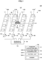
- Fig. 1 is a diagram illustrating a feed device 100 according to an embodiment.
- the feed device 100 includes an array antenna 110, phase shifters 120, a microwave generator 130, a camera 140, and a controller 150.
- An antenna device 100A according to the embodiment includes components of the feed device 100 excepting the microwave generator 130.
- an XYZ coordinate system is used.
- a plan view means a view seen from an XY plane.
- An X-axis is an example of a first axis
- a Y-axis is an example of a second axis
- a Z-axis is an example of a third axis.
- the XY plane is an example of a first plane
- an XZ plane is an example of a second plane.
- the array antenna 110 includes a group of four subarrays 110A, 110B, 110C, and 110D.
- the subarrays 110A to 110D are ranged in an X-axis direction, and each of the subarrays 110A to 110D may include four antenna elements 111, for example.
- the array antenna 110 includes sixteen antenna elements 111.
- Each antenna element 111 is a rectangular patch antenna in a plan view.
- the array antenna 110 may have a ground plate that is set at a ground potential and that is on the -Z direction side of the antenna elements 111. Note that for example, a center determined based on positions of the sixteen antenna elements 111 coincides with the origin of the XYZ coordinate system.
- phase shifters 120 are respectively provided for the four subarrays 110A to 110D, and each of the four phase shifters 120 is connected to given antenna elements 111 of a corresponding subarray among the subarrays 110A to 110D. In each of the subarrays 110A to 110D, four antenna elements 111 are connected in parallel to a corresponding one phase shifter 120.
- Each phase shifter 120 is an example of a phase adjusting unit.
- each of the subarrays 110A to 110D power having the same phase is supplied to each of the four antenna elements 111. Also, power output from the respective four phase shifters 120 to the subarrays 110A to 110D differs from each other in phase. Thus, an angle (elevation angle) of a beam formed by radio waves radiated from the sixteen antenna elements 111 can be adjusted within the XZ plane.
- a beam output from the array antenna 110 is as described in the beam formed by the radio waves radiated from the sixteen antenna elements 111. Also, a beam output from each of the antenna device 100A and the feed device 100 is as described in the beam output from the array antenna 110.
- the microwave generator 130 is connected to each of the four phase shifters 120 and supplies microwaves of predetermined power.
- the microwave generator 130 is an example of a radio wave generator.
- a microwave frequency is 915 MHz.
- the feed device 100 has the configuration that includes the microwave generator 130.
- the microwave is not limiting, and a radio wave of a predetermined frequency may be used.
- the camera 140 is disposed between the subarray 110B and the subarray 110C.
- the camera 140 includes a fisheye lens 141 and a camera body 142.
- the camera 140 is an example of an image capturing unit.
- the fisheye lens 141 is a lens employing an equidistant projection.
- a center of the fisheye lens 141 coincides with each of the above center determined from the sixteen antenna elements 111 and the origin of the XYZ coordinate system.
- the camera body 142 is a portion of the camera 140 other than the fisheye lens 141.
- the camera may be either a camera with a complementary metal oxide semiconductor (CMOS) image sensor or an infrared camera.
- CMOS complementary metal oxide semiconductor
- the camera 140 captures an image with a marker, through the fisheye lens 141, and outputs image data to the controller 150.
- the marker is attached to a target, to which each of the antenna device 100A and the feed device 100 outputs a beam.
- Each of the antenna device 100A and the feed device 100 determines a position of the marker included in a given image captured by the camera 140, and then irradiates the target with a beam.
- the controller 150 includes a position converting unit 151, an elevation-angle acquiring unit 152, a control unit 153, and a memory 154.
- the controller 150 is implemented by a computer including a central processing unit (CPU) and a memory.
- the position converting unit 151, the elevation-angle acquiring unit 152, and the control unit 153, which are functionally implemented by a program that the controller 150 executes, are illustrated using respective functional blocks.
- the memory 154 which is a memory of the controller 150, is functionally illustrated.
- Fig. 2 is a diagram illustrating a polar coordinate system used in the array antenna 110.
- Fig. 2 only the array antenna 110 and the camera 140 of the feed device 100 are illustrated.
- Fig. 2 the polar coordinate system in a plane parallel to the XY plane is illustrated.
- a position of the marker in the XYZ coordinate system is expressed by PI
- an elevation angle associated with a line segment connecting the origin O and the position P1 is expressed by ⁇
- an azimuth angle is expressed by ⁇ .
- the elevation angle is an angle from the +Z direction
- the azimuth angle is an angle from the +X direction
- a counterclockwise direction in a plan view is expressed using a positive value.
- An elevation angle associated with a line segment connecting a position P1a, which is obtained by projecting the position P1 onto the XZ plane, and the origin O, is expressed by ⁇ a.
- the position P1 is an example of a first position, and the position P1a is an example of a projected position.
- the origin O is an example of a reference point in the XYZ coordinate system.
- Each of the antenna device 100A and the feed device 100 adjusts, within only the XZ plane, a given elevation angle of a beam that the array antenna 110 outputs.
- a given position of the target is not greatly displaced from the XZ plane (e.g., the given elevation angle from the Z-axis, within the YZ plane, is approximately within the range of ⁇ 30 degrees, inclusive). This is because when the given target is at such a position, the beam can be delivered to the given target by simply adjusting the elevation angle of the beam within the XZ plane.
- the position converting unit 151 performs image processing with respect to an image captured by the camera 140, to thereby convert coordinates of the image to which an equidistant projection is applied and that is obtained through the fisheye lens 141, into polar coordinates on a plane parallel to the XY plane.
- the position PI which is used in the array antenna 110, of the marker included in the image captured by the camera 140 is converted into a position P2 expressed in polar coordinates on the XY plane.
- the position P2 is an example of a second position.
- the position P2 is expressed with a radius r from the origin O, and a deflection angle ⁇ .
- a focal length of the fisheye lens 141 is given as f L
- the deflection angle ⁇ is identical to the azimuth angle ⁇ .
- the position converting unit 151 calculates r ⁇ cos ⁇ indicating that the radius r is mapped to the X-axis, by the above-described image processing.
- the elevation-angle acquiring unit 152 acquires (determines), as the elevation angle ⁇ a, a value (r ⁇ cos ⁇ / f L ) obtained by dividing an X-coordinate (r ⁇ cos ⁇ ) of a mapped position P2a, by the focal length f L of the fisheye lens 141, where the mapped position P2a is obtained by mapping the position P2 to the X-axis.
- the reason why the elevation angle ⁇ a can be obtained in such a manner will be described below.
- the control unit 153 controls the phase shifters 120 such that a given direction of the beam emitted from the array antenna 110 is derived from the elevation angle ⁇ a within the XZ plane.
- the elevation angle ⁇ a is obtained by the elevation-angle acquiring unit 152.
- the control unit 153 performs an output control of the microwave generator 130, an imaging control of the camera 140, and the like.
- the memory 154 stores a program to be executed when the position converting unit 151, the elevation-angle acquiring unit 152, and the control unit 153 perform processing.
- the memory 154 stores data such as data to be used when the program is executed, data to be generated when the program is executed, and image data that the camera 140 acquires.
- the elevation angle ⁇ a can be determined, as expressed by Equation (1) below, by taking into account the geometric relationship between the position P1 and the position P1a.
- Equation (1) ⁇ 2 ⁇ tan ⁇ 1 1 cos ⁇ tan ⁇ 2 ⁇ ⁇
- Equation (2) can be transformed into Equation (3).
- Equation (3) if the position of a given target is not displaced greatly from the XZ plane, the elevation angle ⁇ a can be approximated as expressed by Equation (3).
- Equation (4) f L ⁇
- the position P2 is calculated by converting coordinates of the position P1, which are obtained by an equidistance projection, into polar coordinates on a plane parallel to the XY plane, and further, an X-coordinate (r ⁇ cos ⁇ ) of a given protected position P2a is divided by the focal length f L of the fisheye lens 141, where the given projected position P2a is obtained by mapping the position P2 to the X axis.
- an antenna device 100A and a feed device 100 that allows a beam direction to be adjusted with a simple calculation can be provided.
- each of the antenna device 100A and the feed device 100 adjusts a given elevation angle of the beam output from the array antenna 110, within only the XZ plane, and thus the number of phase shifters 120 is one-fourth of the number of phase shifters in a case where the elevation angle is adjusted within both the XZ plane and the YZ plane. Accordingly, the antenna device 100A and the feed device 100 can be inexpensively implemented.
- the center of the fisheye lens 141 coincides with the center determined from the sixteen antenna elements 111.
- the center of the fisheye lens 141 may be displaced from the above center of the sixteen antenna elements 111.
- a coordinates origin used in determining the phase for controlling the array antenna may be displaced by an amount of displacement.
- Fig. 3 is a diagram illustrating an example of how the feed device 100 is applied.
- the feed device 100 is provided in a vehicle, and a target antenna 20 is provided on an inner wall 10 of a tunnel.
- a marker 21 is attached to the antenna 20.
- the marker 21 includes a retroreflective reflector, a mirror ball, or the like.
- the antenna 20, a sensor, a rectenna, and a wireless communication module are secured to a fixing portion for fixing an infrastructural object, such as a jet fan or a sign, to the inner wall 10 of the tunnel, where the facility object is attached to the inner wall 10 of the tunnel, and the sensor monitors loosening of a bolt or the like used at the fixing portion.
- the feed device 100 irradiates the antenna 20 with a beam, while the vehicle is traveling
- the rectenna connected to the antenna 20 generates power to thereby cause the wireless communication module to start.
- the wireless communication module radiates a signal indicating the output of the sensor, and the signal is thereby received on the vehicle side.
- a fixed state of the infrastructural object can be inspected while the vehicle is traveling.
- a given signal indicating the output of the sensor, which is radiated by the wireless communication module, may be received through the array antenna 110.
- a given X-coordinate (r ⁇ cos ⁇ ) of a given mapped position is determined by mapping a given position of the antenna 20, which is shifted from the XZ plane, to the X-axis, and then a beam is adjusted by using a given value (r ⁇ cos ⁇ / f L ) obtained by dividing the given X-coordinate (r ⁇ cos ⁇ ) by the focal length f L of the fisheye lens 141, where the given value (r ⁇ cos ⁇ / f L ) is used as a given elevation angle ⁇ a.
- the feed device 100 (antenna device 100A) communicates with the wireless communication module provided on the inner wall 10 of the tunnel has been described with reference to Fig. 3 .
- the wireless communication module is not limited to being provided on the inner wall 10 of the tunnel, and may be provided at various positions, or the like. In such a manner, the feed device 100 (antenna device 100A) can be used as a communication device.
Landscapes
- Variable-Direction Aerials And Aerial Arrays (AREA)
- Aerials With Secondary Devices (AREA)
- Image Analysis (AREA)
- Engineering & Computer Science (AREA)
- Computer Vision & Pattern Recognition (AREA)
- Physics & Mathematics (AREA)
- General Physics & Mathematics (AREA)
- Theoretical Computer Science (AREA)
Abstract
Description
- The present invention relates to an antenna device and a feed device.
- The conventional antenna device includes antenna sections each of which has multiple antenna elements arranged in an array pattern or subarray pattern (see, for example, Patent document 1).
- [Patent document 1] Published
Japanese Translation of PCT International Application No. 2008-523708 - In order to adjust directions of beams formed by radio waves that are emitted from multiple antenna elements, when the directions of the beams are adjusted using elevation angles and azimuth angles, it may involve complicated calculations.
- Accordingly, an object is to provide an antenna device and a feed device that allows a beam direction to be adjusted with a simple calculation.
- An antenna device according to an embodiment of the present invention includes an array antenna with multiple antenna elements that are arranged in two dimensions, the multiple antenna elements being arranged along each of a first axis and a second axis. The antenna device includes at least one phase adjusting unit configured to adjust, with respect to a first axial direction, a phase of power supplied to each of the multiple antenna elements. The antenna device includes an image capturing unit configured to capture an image through a fisheye lens. The antenna device includes a position converting unit configured to convert a first position, which is used in the image capturing unit, of a marker included in the image captured by the image capturing unit, into a second position of polar coordinates on a first plane that includes the first axis and the second axis. The antenna device includes an elevation-angle acquiring unit configured to determine, within a second plane that includes the first axis and a third axis, an elevation angle of a projected position relative to the third axis, based on the second position, the projected position being obtained by projecting the first position onto the second plane. The antenna device includes a control unit configured to control the phase adjusting unit such that a direction of a beam radiated through the array antenna is derived from the elevation angle within the second plane.
- An antenna device and a feed device that allows a beam direction to be adjusted with a simple calculation are provided.
-
- [
Fig. 1 ]
Fig. 1 is a diagram illustrating afeed device 100 according to an embodiment; - [
Fig. 2 ]
Fig. 2 is a diagram illustrating a polar coordinate system used in anarray antenna 110; and - [
Fig. 3 ]
Fig. 3 is a diagram illustrating an example of how thefeed device 100 is applied. - One or more embodiments in which an antenna device and a feed device according to the present invention are applied are described below.
-
Fig. 1 is a diagram illustrating afeed device 100 according to an embodiment. Thefeed device 100 includes anarray antenna 110,phase shifters 120, amicrowave generator 130, acamera 140, and acontroller 150. Anantenna device 100A according to the embodiment includes components of thefeed device 100 excepting themicrowave generator 130. - In the following description, an XYZ coordinate system is used. A plan view means a view seen from an XY plane. An X-axis is an example of a first axis, a Y-axis is an example of a second axis, and a Z-axis is an example of a third axis. The XY plane is an example of a first plane, and an XZ plane is an example of a second plane.
- As an example, the
array antenna 110 includes a group of foursubarrays subarrays 110A to 110D are ranged in an X-axis direction, and each of thesubarrays 110A to 110D may include fourantenna elements 111, for example. In this case, for example, thearray antenna 110 includes sixteenantenna elements 111. Eachantenna element 111 is a rectangular patch antenna in a plan view. Thearray antenna 110 may have a ground plate that is set at a ground potential and that is on the -Z direction side of theantenna elements 111. Note that for example, a center determined based on positions of the sixteenantenna elements 111 coincides with the origin of the XYZ coordinate system. - Four
phase shifters 120 are respectively provided for the foursubarrays 110A to 110D, and each of the fourphase shifters 120 is connected to givenantenna elements 111 of a corresponding subarray among thesubarrays 110A to 110D. In each of thesubarrays 110A to 110D, fourantenna elements 111 are connected in parallel to a corresponding onephase shifter 120. Eachphase shifter 120 is an example of a phase adjusting unit. - In each of the
subarrays 110A to 110D, power having the same phase is supplied to each of the fourantenna elements 111. Also, power output from the respective fourphase shifters 120 to thesubarrays 110A to 110D differs from each other in phase. Thus, an angle (elevation angle) of a beam formed by radio waves radiated from the sixteenantenna elements 111 can be adjusted within the XZ plane. - A beam output from the
array antenna 110 is as described in the beam formed by the radio waves radiated from the sixteenantenna elements 111. Also, a beam output from each of theantenna device 100A and thefeed device 100 is as described in the beam output from thearray antenna 110. - The
microwave generator 130 is connected to each of the fourphase shifters 120 and supplies microwaves of predetermined power. Themicrowave generator 130 is an example of a radio wave generator. For example, a microwave frequency is 915 MHz. Note that in this description, thefeed device 100 has the configuration that includes themicrowave generator 130. However, the microwave is not limiting, and a radio wave of a predetermined frequency may be used. - The
camera 140 is disposed between the subarray 110B and the subarray 110C. Thecamera 140 includes afisheye lens 141 and acamera body 142. Thecamera 140 is an example of an image capturing unit. - The
fisheye lens 141 is a lens employing an equidistant projection. For example, a center of thefisheye lens 141 coincides with each of the above center determined from the sixteenantenna elements 111 and the origin of the XYZ coordinate system. Thecamera body 142 is a portion of thecamera 140 other than thefisheye lens 141. The camera may be either a camera with a complementary metal oxide semiconductor (CMOS) image sensor or an infrared camera. - The
camera 140 captures an image with a marker, through thefisheye lens 141, and outputs image data to thecontroller 150. The marker is attached to a target, to which each of theantenna device 100A and thefeed device 100 outputs a beam. Each of theantenna device 100A and thefeed device 100 determines a position of the marker included in a given image captured by thecamera 140, and then irradiates the target with a beam. - The
controller 150 includes aposition converting unit 151, an elevation-angle acquiring unit 152, acontrol unit 153, and amemory 154. Thecontroller 150 is implemented by a computer including a central processing unit (CPU) and a memory. Theposition converting unit 151, the elevation-angle acquiring unit 152, and thecontrol unit 153, which are functionally implemented by a program that thecontroller 150 executes, are illustrated using respective functional blocks. Thememory 154, which is a memory of thecontroller 150, is functionally illustrated. - Hereafter, the
position converting unit 151, the elevation-angle acquiring unit 152, thecontrol unit 153, and thememory 154 will be described with reference toFig. 2 together withFig. 1 .Fig. 2 is a diagram illustrating a polar coordinate system used in thearray antenna 110. InFig. 2 , only thearray antenna 110 and thecamera 140 of thefeed device 100 are illustrated. Also, inFig. 2 , the polar coordinate system in a plane parallel to the XY plane is illustrated. - Moreover, a position of the marker in the XYZ coordinate system is expressed by PI, an elevation angle associated with a line segment connecting the origin O and the position P1 is expressed by θ, and an azimuth angle is expressed by ϕ. The elevation angle is an angle from the +Z direction, the azimuth angle is an angle from the +X direction, and a counterclockwise direction in a plan view is expressed using a positive value. An elevation angle associated with a line segment connecting a position P1a, which is obtained by projecting the position P1 onto the XZ plane, and the origin O, is expressed by θa.
- The position P1 is an example of a first position, and the position P1a is an example of a projected position. The origin O is an example of a reference point in the XYZ coordinate system.
- Each of the
antenna device 100A and thefeed device 100 adjusts, within only the XZ plane, a given elevation angle of a beam that thearray antenna 110 outputs. In this regard, it is assumed that a given position of the target is not greatly displaced from the XZ plane (e.g., the given elevation angle from the Z-axis, within the YZ plane, is approximately within the range of ±30 degrees, inclusive). This is because when the given target is at such a position, the beam can be delivered to the given target by simply adjusting the elevation angle of the beam within the XZ plane. - The
position converting unit 151 performs image processing with respect to an image captured by thecamera 140, to thereby convert coordinates of the image to which an equidistant projection is applied and that is obtained through thefisheye lens 141, into polar coordinates on a plane parallel to the XY plane. By the image processing, the position PI, which is used in thearray antenna 110, of the marker included in the image captured by thecamera 140 is converted into a position P2 expressed in polar coordinates on the XY plane. The position P2 is an example of a second position. - The position P2 is expressed with a radius r from the origin O, and a deflection angle ϕ. When a focal length of the
fisheye lens 141 is given as fL, the radius r is expressed by r = fLθ. The deflection angle ϕ is identical to the azimuth angle ϕ. Theposition converting unit 151 calculates r·cosϕ indicating that the radius r is mapped to the X-axis, by the above-described image processing. - The elevation-
angle acquiring unit 152 acquires (determines), as the elevation angle θa, a value (r· cosϕ / fL) obtained by dividing an X-coordinate (r· cosϕ) of a mapped position P2a, by the focal length fL of thefisheye lens 141, where the mapped position P2a is obtained by mapping the position P2 to the X-axis. The reason why the elevation angle θa can be obtained in such a manner will be described below. - The
control unit 153 controls thephase shifters 120 such that a given direction of the beam emitted from thearray antenna 110 is derived from the elevation angle θa within the XZ plane. The elevation angle θa is obtained by the elevation-angle acquiring unit 152. Thecontrol unit 153 performs an output control of themicrowave generator 130, an imaging control of thecamera 140, and the like. - The
memory 154 stores a program to be executed when theposition converting unit 151, the elevation-angle acquiring unit 152, and thecontrol unit 153 perform processing. Thememory 154 stores data such as data to be used when the program is executed, data to be generated when the program is executed, and image data that thecamera 140 acquires. - Hereafter, a method for determining the elevation angle θa will be described.
- When the azimuth angle ϕ and the elevation angle θ are used, the elevation angle θa can be determined, as expressed by Equation (1) below, by taking into account the geometric relationship between the position P1 and the position P1a.
[Math. 1]
- When Equation (1) is expanded, Equation (2) is obtained.
[Math. 2]
- Here, if the elevation angle θ is sufficiently small, "tanθ ≒ θ" is satisfied; if the azimuth angle ϕ is sufficiently small, "cosϕ ≒ 1" is satisfied; and, if the azimuth angle ϕ is close to 90 degrees, "cosϕ ≒ 0" is satisfied, accordingly, then Equation (2) can be transformed into Equation (3).
[Math. 3]
- In other words, if the position of a given target is not displaced greatly from the XZ plane, the elevation angle θa can be approximated as expressed by Equation (3).
- Further, as described above, when the focal length fL of the
fisheye lens 141 is given as fL, the radius r is expressed by Equation (4) below.

- As described above, when a given elevation angle of the beam from the
array antenna 110 is adjusted within only the XZ plane, the position P2 is calculated by converting coordinates of the position P1, which are obtained by an equidistance projection, into polar coordinates on a plane parallel to the XY plane, and further, an X-coordinate (r · cosϕ) of a given protected position P2a is divided by the focal length fL of thefisheye lens 141, where the given projected position P2a is obtained by mapping the position P2 to the X axis. Thus, the elevation angle θa (= r · cosϕ / fL) can be determined. - Accordingly, an
antenna device 100A and afeed device 100 that allows a beam direction to be adjusted with a simple calculation can be provided. - Also, each of the
antenna device 100A and thefeed device 100 adjusts a given elevation angle of the beam output from thearray antenna 110, within only the XZ plane, and thus the number ofphase shifters 120 is one-fourth of the number of phase shifters in a case where the elevation angle is adjusted within both the XZ plane and the YZ plane. Accordingly, theantenna device 100A and thefeed device 100 can be inexpensively implemented. - Note that in the above description, the center of the
fisheye lens 141 coincides with the center determined from the sixteenantenna elements 111. However, the center of thefisheye lens 141 may be displaced from the above center of the sixteenantenna elements 111. In this case, a coordinates origin used in determining the phase for controlling the array antenna may be displaced by an amount of displacement. -
Fig. 3 is a diagram illustrating an example of how thefeed device 100 is applied. For example, thefeed device 100 is provided in a vehicle, and atarget antenna 20 is provided on aninner wall 10 of a tunnel. Amarker 21 is attached to theantenna 20. Themarker 21 includes a retroreflective reflector, a mirror ball, or the like. - When the vehicle travels in the +X direction, the
camera 140 is used to convert coordinates of a position of themarker 21 into polar coordinates in a plane parallel to an XY plane, and then a beam is delivered to theantenna 20 by using a given elevation angle θa (= r · cosϕ / fL), which is determined by dividing an X-coordinate (r · cosϕ) of a mapped position (mapped position corresponding to P2a), by the focal length fL of thefisheye lens 141, where the mapped position is obtained by mapping the position of the polar coordinates onto the X-axis. - For example, the
antenna 20, a sensor, a rectenna, and a wireless communication module are secured to a fixing portion for fixing an infrastructural object, such as a jet fan or a sign, to theinner wall 10 of the tunnel, where the facility object is attached to theinner wall 10 of the tunnel, and the sensor monitors loosening of a bolt or the like used at the fixing portion. In such a manner, when thefeed device 100 irradiates theantenna 20 with a beam, while the vehicle is traveling, the rectenna connected to theantenna 20 generates power to thereby cause the wireless communication module to start. Then, the wireless communication module radiates a signal indicating the output of the sensor, and the signal is thereby received on the vehicle side. Thus, a fixed state of the infrastructural object can be inspected while the vehicle is traveling. - In this case, a given signal indicating the output of the sensor, which is radiated by the wireless communication module, may be received through the
array antenna 110. - Also, a given X-coordinate (r · cosϕ) of a given mapped position (mapped position corresponding to P2a) is determined by mapping a given position of the
antenna 20, which is shifted from the XZ plane, to the X-axis, and then a beam is adjusted by using a given value (r · cosϕ / fL) obtained by dividing the given X-coordinate (r · cosϕ) by the focal length fL of thefisheye lens 141, where the given value (r · cosϕ / fL) is used as a given elevation angle θa. Thus, even when the vehicle traveling in the X-axis direction shifts toward either a positive side or negative side of the Y-axis, displacement due to the shift is reduced, thereby enabling the given elevation angle θa to be determined. - In this description, the case where the feed device 100 (
antenna device 100A) communicates with the wireless communication module provided on theinner wall 10 of the tunnel has been described with reference toFig. 3 . However, the wireless communication module is not limited to being provided on theinner wall 10 of the tunnel, and may be provided at various positions, or the like. In such a manner, the feed device 100 (antenna device 100A) can be used as a communication device. - Although the antenna device and feed device according to the illustrative embodiment of the present invention have been described, the present invention is not limited to the embodiment disclosed specifically. Various modifications and changes can be made without departing from the claims.
- This International application claims priority to
Japanese Patent Application No. 2019-028376, filed February 20, 2019 -
- 100
- feed device
- 110
- array antenna
- 110A
- to 110D subarray
- 111
- antenna element
- 120
- phase shifter
- 130
- microwave generator
- 140
- camera
- 141
- fisheye lens
- 150
- controller
- 151
- position converting unit
- 152
- elevation-angle acquiring unit
- 153
- control unit
Claims (6)
- An antenna device comprising:an array antenna with multiple antenna elements that are arranged in two dimensions, the multiple antenna elements being arranged along each of a first axis and a second axis;at least one phase adjusting unit configured to adjust, with respect to a first axial direction, a phase of power supplied to each of the multiple antenna elements;an image capturing unit configured to capture an image through a fisheye lens;a position converting unit configured to convert a first position, which is used in the image capturing unit, of a marker included in the image captured by the image capturing unit, into a second position of polar coordinates on a first plane that includes the first axis and the second axis;an elevation-angle acquiring unit configured to determine, within a second plane that includes the first axis and a third axis, an elevation angle of a projected position relative to the third axis, based on the second position, the projected position being obtained by projecting the first position onto the second plane; anda control unit configured to control the phase adjusting unit such that a direction of a beam radiated through the array antenna is derived from the elevation angle within the second plane.
- The antenna device according to claim 1, wherein the elevation-angle acquiring unit is configured to determine, as the elevation angle, a value obtained by dividing a coordinate of a projected position by a focal length of the fisheye lens, the coordinate of the projected position being obtained by mapping the second position to the first axis.
- The antenna device according to claim 2, wherein the coordinate of the projected position is expressed with a value obtained by multiplying a radius by a cosine of a deflection angle, the radius and the deflection angle being represented in the polar coordinates.
- The antenna device according to any one of claims 1 to 3, wherein the multiple antenna elements are grouped into multiple subarrays each of which extends along the second axis, and
wherein the at least one phase adjusting unit is multiple phase shifters connected to the respective multiple subarrays, each phase shifter being configured to adjust the phase of the power, for each subarray. - The antenna device according to claim 4, wherein power having a same phase is supplied to each of given antenna elements included in a same subarray.
- A feed device comprising:an array antenna with multiple antenna elements that are arranged in two dimensions, the multiple antenna elements being arranged along each of a first axis and a second axis;a radio wave generator;at least one phase adjusting unit provided between the array antenna and the radio wave generator, the phase adjusting unit being configured to adjust, with respect to the first axis, a phase of power that is supplied by the radio wave generator to each of the multiple antenna elements;an image capturing unit configured to capture an image through a fisheye lens;a position converting unit configured to convert a first position, which is used in the image capturing unit, of a marker included in the image captured by the image capturing unit, into a second position of polar coordinates on a first plane that includes the first axis and the second axis;an elevation-angle acquiring unit configured to determine, within a second plane that includes the first axis and a third axis, an elevation angle of a projected position relative to the third axis, based on the second position, the projected position being obtained by projecting the first position onto the second plane; anda control unit configured to control the phase adjusting unit such that a direction of a beam radiated through the array antenna is derived from the elevation angle within the second plane.
Applications Claiming Priority (2)
| Application Number | Priority Date | Filing Date | Title |
|---|---|---|---|
| JP2019028376A JP6795637B2 (en) | 2019-02-20 | 2019-02-20 | Antenna device and power supply device |
| PCT/JP2019/043255 WO2020170508A1 (en) | 2019-02-20 | 2019-11-05 | Antenna device and power feeding device |
Publications (3)
| Publication Number | Publication Date |
|---|---|
| EP3913744A1 true EP3913744A1 (en) | 2021-11-24 |
| EP3913744A4 EP3913744A4 (en) | 2022-03-09 |
| EP3913744B1 EP3913744B1 (en) | 2025-01-01 |
Family
ID=72144003
Family Applications (1)
| Application Number | Title | Priority Date | Filing Date |
|---|---|---|---|
| EP19915858.5A Active EP3913744B1 (en) | 2019-02-20 | 2019-11-05 | Antenna device and power feeding device |
Country Status (5)
| Country | Link |
|---|---|
| US (1) | US12046830B2 (en) |
| EP (1) | EP3913744B1 (en) |
| JP (1) | JP6795637B2 (en) |
| CN (1) | CN113454846B (en) |
| WO (1) | WO2020170508A1 (en) |
Families Citing this family (9)
| Publication number | Priority date | Publication date | Assignee | Title |
|---|---|---|---|---|
| JP7593587B2 (en) | 2020-09-10 | 2024-12-03 | ミネベアミツミ株式会社 | Antenna device, power supply device, and power supply method |
| JP7613740B2 (en) * | 2021-06-16 | 2025-01-15 | ミネベアミツミ株式会社 | Antenna device, power supply system, power supply device, and power supply method |
| JP7658060B2 (en) | 2021-07-01 | 2025-04-08 | ミネベアミツミ株式会社 | Antenna device, power supply device, and power supply method |
| JP7740653B2 (en) * | 2021-08-02 | 2025-09-17 | ミネベアミツミ株式会社 | Distance estimation device, antenna device, power supply system, power supply device, and power supply method |
| JP7708415B2 (en) * | 2021-08-02 | 2025-07-15 | ミネベアミツミ株式会社 | Distance estimation device, antenna device, power supply system, power supply device, and power supply method |
| JP7729514B2 (en) * | 2022-06-15 | 2025-08-26 | ミネベアミツミ株式会社 | Antenna device, power supply device, and power supply method |
| JP7754390B2 (en) * | 2022-06-22 | 2025-10-15 | ミネベアミツミ株式会社 | Power supply device and power supply method |
| US20260051666A1 (en) * | 2022-09-05 | 2026-02-19 | Minebea Mitsumi Inc. | Antenna device, power feeding apparatus, and power feeding method |
| US12580613B2 (en) * | 2024-02-06 | 2026-03-17 | International Business Machines Corporation | Arbitrary spatial filters based on beam transformation |
Family Cites Families (28)
| Publication number | Priority date | Publication date | Assignee | Title |
|---|---|---|---|---|
| US5185667A (en) * | 1991-05-13 | 1993-02-09 | Telerobotics International, Inc. | Omniview motionless camera orientation system |
| US5313306A (en) | 1991-05-13 | 1994-05-17 | Telerobotics International, Inc. | Omniview motionless camera endoscopy system |
| JPH10163721A (en) | 1996-12-04 | 1998-06-19 | Nikon Corp | GPS antenna |
| KR100792267B1 (en) | 2003-02-22 | 2008-01-07 | 퓰러렌 사이언시즈, 인코포레이티드 | Laser pyrolysis method for producing carbon nano-spheres |
| US20090289864A1 (en) | 2004-12-13 | 2009-11-26 | Anders Derneryd | Antenna Arrangement And A Method Relating Thereto |
| JP4631048B2 (en) * | 2005-02-14 | 2011-02-16 | 国立大学法人岩手大学 | Imaging apparatus and imaging system parameter calibration method |
| US7064710B1 (en) * | 2005-02-15 | 2006-06-20 | The Aerospace Corporation | Multiple beam steered subarrays antenna system |
| JP4716896B2 (en) * | 2006-02-22 | 2011-07-06 | 株式会社トヨタIt開発センター | Communication area control device, communication area control method, in-vehicle device |
| JP4661829B2 (en) | 2007-06-14 | 2011-03-30 | 株式会社富士通ゼネラル | Image data conversion device and camera device provided with the same |
| JP5234372B2 (en) | 2008-02-29 | 2013-07-10 | オムロン株式会社 | Array antenna, tag communication apparatus, tag communication system, and array antenna beam control method |
| JP5372055B2 (en) * | 2011-03-24 | 2013-12-18 | 日本電信電話株式会社 | Wireless communication apparatus and beam control method |
| JP5579691B2 (en) | 2011-12-06 | 2014-08-27 | 中国電力株式会社 | POSITIONING SYSTEM, MOBILE TERMINAL, AND POSITIONING SYSTEM CONTROL METHOD |
| JP5966341B2 (en) | 2011-12-19 | 2016-08-10 | 大日本印刷株式会社 | Image processing apparatus, image processing method, program for image processing apparatus, and image display apparatus |
| RU2605158C2 (en) | 2012-09-20 | 2016-12-20 | Нек Корпорейшн | Auxiliary device for adjusting orientation of antenna and method of mounting antenna device |
| JP5666069B1 (en) | 2013-06-24 | 2015-02-12 | 三菱電機株式会社 | Coordinate calculation apparatus and method, and image processing apparatus and method |
| CN103984836B (en) * | 2014-05-30 | 2017-06-23 | 电子科技大学 | A kind of stored in association method of 3D mimo antennas polarized gain |
| JP6387450B2 (en) | 2015-02-18 | 2018-09-05 | 富士フイルム株式会社 | Tracking shooting control device, tracking shooting system, camera, terminal device, tracking shooting method, tracking shooting program |
| EP3249429B1 (en) * | 2016-05-27 | 2019-05-01 | Centre National d'Etudes Spatiales | Adaptive antenna assembly for improving precision of a gnss receiver in a perturbated environment |
| WO2017217411A1 (en) | 2016-06-17 | 2017-12-21 | 日本電気株式会社 | Image processing device, image processing method, and recording medium |
| CN106570938A (en) * | 2016-10-21 | 2017-04-19 | 哈尔滨工业大学深圳研究生院 | OPENGL based panoramic monitoring method and system |
| EP3340378A1 (en) | 2016-12-22 | 2018-06-27 | Centre National d'Etudes Spatiales | A simplified gnss receiver with improved precision in a perturbated environment |
| JP6712240B2 (en) * | 2017-02-28 | 2020-06-17 | 日本電信電話株式会社 | Wireless communication device and wireless communication method |
| JP2019028376A (en) | 2017-08-03 | 2019-02-21 | オリンパス株式会社 | Observation container and observation method |
| CN107911789B (en) | 2017-11-24 | 2019-12-24 | 李斌 | Radio wave positioning system, positioning and charging method based on fisheye lens |
| JP7069232B2 (en) * | 2020-02-27 | 2022-05-17 | ミネベアミツミ株式会社 | Power supply system, power supply device, and power supply method |
| JP7593587B2 (en) * | 2020-09-10 | 2024-12-03 | ミネベアミツミ株式会社 | Antenna device, power supply device, and power supply method |
| JP7613740B2 (en) * | 2021-06-16 | 2025-01-15 | ミネベアミツミ株式会社 | Antenna device, power supply system, power supply device, and power supply method |
| JP7740653B2 (en) * | 2021-08-02 | 2025-09-17 | ミネベアミツミ株式会社 | Distance estimation device, antenna device, power supply system, power supply device, and power supply method |
-
2019
- 2019-02-20 JP JP2019028376A patent/JP6795637B2/en active Active
- 2019-11-05 EP EP19915858.5A patent/EP3913744B1/en active Active
- 2019-11-05 US US17/310,560 patent/US12046830B2/en active Active
- 2019-11-05 CN CN201980092201.XA patent/CN113454846B/en active Active
- 2019-11-05 WO PCT/JP2019/043255 patent/WO2020170508A1/en not_active Ceased
Also Published As
| Publication number | Publication date |
|---|---|
| US20220021112A1 (en) | 2022-01-20 |
| EP3913744A4 (en) | 2022-03-09 |
| CN113454846A (en) | 2021-09-28 |
| CN113454846B (en) | 2024-09-27 |
| US12046830B2 (en) | 2024-07-23 |
| WO2020170508A1 (en) | 2020-08-27 |
| EP3913744B1 (en) | 2025-01-01 |
| JP2020136918A (en) | 2020-08-31 |
| JP6795637B2 (en) | 2020-12-02 |
Similar Documents
| Publication | Publication Date | Title |
|---|---|---|
| EP3913744B1 (en) | Antenna device and power feeding device | |
| JP7593587B2 (en) | Antenna device, power supply device, and power supply method | |
| US12095286B2 (en) | Power supply system, power supply device, and power supply method | |
| JP7613740B2 (en) | Antenna device, power supply system, power supply device, and power supply method | |
| WO2023276369A1 (en) | Antenna device, power supply device, and power supply method | |
| JP7740653B2 (en) | Distance estimation device, antenna device, power supply system, power supply device, and power supply method | |
| JP2003315441A (en) | Axis adjustment device and axis adjustment method for vehicle-mounted radar device | |
| JP7708415B2 (en) | Distance estimation device, antenna device, power supply system, power supply device, and power supply method | |
| JP2023183133A (en) | Antenna device, power supply device, and power supply method | |
| US20260051666A1 (en) | Antenna device, power feeding apparatus, and power feeding method | |
| US20240022820A1 (en) | Observation apparatus and adjustment method | |
| JP2024127557A (en) | Position detection system and position detection method | |
| JP2024001662A (en) | Power supply device and power supply method | |
| JPWO2024134815A5 (en) | ||
| JPH0423226B2 (en) |
Legal Events
| Date | Code | Title | Description |
|---|---|---|---|
| STAA | Information on the status of an ep patent application or granted ep patent |
Free format text: STATUS: THE INTERNATIONAL PUBLICATION HAS BEEN MADE |
|
| PUAI | Public reference made under article 153(3) epc to a published international application that has entered the european phase |
Free format text: ORIGINAL CODE: 0009012 |
|
| STAA | Information on the status of an ep patent application or granted ep patent |
Free format text: STATUS: REQUEST FOR EXAMINATION WAS MADE |
|
| 17P | Request for examination filed |
Effective date: 20210817 |
|
| AK | Designated contracting states |
Kind code of ref document: A1 Designated state(s): AL AT BE BG CH CY CZ DE DK EE ES FI FR GB GR HR HU IE IS IT LI LT LU LV MC MK MT NL NO PL PT RO RS SE SI SK SM TR |
|
| A4 | Supplementary search report drawn up and despatched |
Effective date: 20220207 |
|
| RIC1 | Information provided on ipc code assigned before grant |
Ipc: H01Q 21/06 20060101ALN20220201BHEP Ipc: G06T 7/70 20170101ALI20220201BHEP Ipc: G06T 3/00 20060101ALI20220201BHEP Ipc: H01Q 5/22 20150101ALI20220201BHEP Ipc: H01Q 3/30 20060101AFI20220201BHEP |
|
| DAV | Request for validation of the european patent (deleted) | ||
| DAX | Request for extension of the european patent (deleted) | ||
| GRAP | Despatch of communication of intention to grant a patent |
Free format text: ORIGINAL CODE: EPIDOSNIGR1 |
|
| STAA | Information on the status of an ep patent application or granted ep patent |
Free format text: STATUS: GRANT OF PATENT IS INTENDED |
|
| RIC1 | Information provided on ipc code assigned before grant |
Ipc: H01Q 21/06 20060101ALN20240531BHEP Ipc: H01Q 5/22 20150101ALI20240531BHEP Ipc: H01Q 3/30 20060101AFI20240531BHEP |
|
| INTG | Intention to grant announced |
Effective date: 20240704 |
|
| RIC1 | Information provided on ipc code assigned before grant |
Ipc: H01Q 21/06 20060101ALN20240624BHEP Ipc: H01Q 5/22 20150101ALI20240624BHEP Ipc: H01Q 3/30 20060101AFI20240624BHEP |
|
| GRAS | Grant fee paid |
Free format text: ORIGINAL CODE: EPIDOSNIGR3 |
|
| P01 | Opt-out of the competence of the unified patent court (upc) registered |
Free format text: CASE NUMBER: APP_52607/2024 Effective date: 20240919 |
|
| GRAA | (expected) grant |
Free format text: ORIGINAL CODE: 0009210 |
|
| STAA | Information on the status of an ep patent application or granted ep patent |
Free format text: STATUS: THE PATENT HAS BEEN GRANTED |
|
| AK | Designated contracting states |
Kind code of ref document: B1 Designated state(s): AL AT BE BG CH CY CZ DE DK EE ES FI FR GB GR HR HU IE IS IT LI LT LU LV MC MK MT NL NO PL PT RO RS SE SI SK SM TR |
|
| REG | Reference to a national code |
Ref country code: GB Ref legal event code: FG4D |
|
| REG | Reference to a national code |
Ref country code: DE Ref legal event code: R096 Ref document number: 602019064460 Country of ref document: DE |
|
| REG | Reference to a national code |
Ref country code: CH Ref legal event code: EP |
|
| REG | Reference to a national code |
Ref country code: IE Ref legal event code: FG4D |
|
| REG | Reference to a national code |
Ref country code: LT Ref legal event code: MG9D |
|
| REG | Reference to a national code |
Ref country code: NL Ref legal event code: MP Effective date: 20250101 |
|
| REG | Reference to a national code |
Ref country code: AT Ref legal event code: MK05 Ref document number: 1757277 Country of ref document: AT Kind code of ref document: T Effective date: 20250101 |
|
| PG25 | Lapsed in a contracting state [announced via postgrant information from national office to epo] |
Ref country code: NL Free format text: LAPSE BECAUSE OF FAILURE TO SUBMIT A TRANSLATION OF THE DESCRIPTION OR TO PAY THE FEE WITHIN THE PRESCRIBED TIME-LIMIT Effective date: 20250101 |
|
| PG25 | Lapsed in a contracting state [announced via postgrant information from national office to epo] |
Ref country code: FI Free format text: LAPSE BECAUSE OF FAILURE TO SUBMIT A TRANSLATION OF THE DESCRIPTION OR TO PAY THE FEE WITHIN THE PRESCRIBED TIME-LIMIT Effective date: 20250101 |
|
| PG25 | Lapsed in a contracting state [announced via postgrant information from national office to epo] |
Ref country code: PL Free format text: LAPSE BECAUSE OF FAILURE TO SUBMIT A TRANSLATION OF THE DESCRIPTION OR TO PAY THE FEE WITHIN THE PRESCRIBED TIME-LIMIT Effective date: 20250101 |
|
| PG25 | Lapsed in a contracting state [announced via postgrant information from national office to epo] |
Ref country code: ES Free format text: LAPSE BECAUSE OF FAILURE TO SUBMIT A TRANSLATION OF THE DESCRIPTION OR TO PAY THE FEE WITHIN THE PRESCRIBED TIME-LIMIT Effective date: 20250101 |
|
| PG25 | Lapsed in a contracting state [announced via postgrant information from national office to epo] |
Ref country code: NO Free format text: LAPSE BECAUSE OF FAILURE TO SUBMIT A TRANSLATION OF THE DESCRIPTION OR TO PAY THE FEE WITHIN THE PRESCRIBED TIME-LIMIT Effective date: 20250401 Ref country code: IS Free format text: LAPSE BECAUSE OF FAILURE TO SUBMIT A TRANSLATION OF THE DESCRIPTION OR TO PAY THE FEE WITHIN THE PRESCRIBED TIME-LIMIT Effective date: 20250501 |
|
| PG25 | Lapsed in a contracting state [announced via postgrant information from national office to epo] |
Ref country code: HR Free format text: LAPSE BECAUSE OF FAILURE TO SUBMIT A TRANSLATION OF THE DESCRIPTION OR TO PAY THE FEE WITHIN THE PRESCRIBED TIME-LIMIT Effective date: 20250101 |
|
| PG25 | Lapsed in a contracting state [announced via postgrant information from national office to epo] |
Ref country code: PT Free format text: LAPSE BECAUSE OF FAILURE TO SUBMIT A TRANSLATION OF THE DESCRIPTION OR TO PAY THE FEE WITHIN THE PRESCRIBED TIME-LIMIT Effective date: 20250502 Ref country code: LV Free format text: LAPSE BECAUSE OF FAILURE TO SUBMIT A TRANSLATION OF THE DESCRIPTION OR TO PAY THE FEE WITHIN THE PRESCRIBED TIME-LIMIT Effective date: 20250101 |
|
| PG25 | Lapsed in a contracting state [announced via postgrant information from national office to epo] |
Ref country code: GR Free format text: LAPSE BECAUSE OF FAILURE TO SUBMIT A TRANSLATION OF THE DESCRIPTION OR TO PAY THE FEE WITHIN THE PRESCRIBED TIME-LIMIT Effective date: 20250402 Ref country code: BG Free format text: LAPSE BECAUSE OF FAILURE TO SUBMIT A TRANSLATION OF THE DESCRIPTION OR TO PAY THE FEE WITHIN THE PRESCRIBED TIME-LIMIT Effective date: 20250101 |
|
| PG25 | Lapsed in a contracting state [announced via postgrant information from national office to epo] |
Ref country code: AT Free format text: LAPSE BECAUSE OF FAILURE TO SUBMIT A TRANSLATION OF THE DESCRIPTION OR TO PAY THE FEE WITHIN THE PRESCRIBED TIME-LIMIT Effective date: 20250101 |
|
| PG25 | Lapsed in a contracting state [announced via postgrant information from national office to epo] |
Ref country code: CZ Free format text: LAPSE BECAUSE OF FAILURE TO SUBMIT A TRANSLATION OF THE DESCRIPTION OR TO PAY THE FEE WITHIN THE PRESCRIBED TIME-LIMIT Effective date: 20250101 |
|
| PG25 | Lapsed in a contracting state [announced via postgrant information from national office to epo] |
Ref country code: SE Free format text: LAPSE BECAUSE OF FAILURE TO SUBMIT A TRANSLATION OF THE DESCRIPTION OR TO PAY THE FEE WITHIN THE PRESCRIBED TIME-LIMIT Effective date: 20250101 |
|
| REG | Reference to a national code |
Ref country code: DE Ref legal event code: R097 Ref document number: 602019064460 Country of ref document: DE |
|
| PG25 | Lapsed in a contracting state [announced via postgrant information from national office to epo] |
Ref country code: SM Free format text: LAPSE BECAUSE OF FAILURE TO SUBMIT A TRANSLATION OF THE DESCRIPTION OR TO PAY THE FEE WITHIN THE PRESCRIBED TIME-LIMIT Effective date: 20250101 |
|
| PG25 | Lapsed in a contracting state [announced via postgrant information from national office to epo] |
Ref country code: DK Free format text: LAPSE BECAUSE OF FAILURE TO SUBMIT A TRANSLATION OF THE DESCRIPTION OR TO PAY THE FEE WITHIN THE PRESCRIBED TIME-LIMIT Effective date: 20250101 |
|
| PG25 | Lapsed in a contracting state [announced via postgrant information from national office to epo] |
Ref country code: IT Free format text: LAPSE BECAUSE OF FAILURE TO SUBMIT A TRANSLATION OF THE DESCRIPTION OR TO PAY THE FEE WITHIN THE PRESCRIBED TIME-LIMIT Effective date: 20250101 |
|
| PG25 | Lapsed in a contracting state [announced via postgrant information from national office to epo] |
Ref country code: EE Free format text: LAPSE BECAUSE OF FAILURE TO SUBMIT A TRANSLATION OF THE DESCRIPTION OR TO PAY THE FEE WITHIN THE PRESCRIBED TIME-LIMIT Effective date: 20250101 |
|
| PG25 | Lapsed in a contracting state [announced via postgrant information from national office to epo] |
Ref country code: RO Free format text: LAPSE BECAUSE OF FAILURE TO SUBMIT A TRANSLATION OF THE DESCRIPTION OR TO PAY THE FEE WITHIN THE PRESCRIBED TIME-LIMIT Effective date: 20250101 |
|
| PG25 | Lapsed in a contracting state [announced via postgrant information from national office to epo] |
Ref country code: SK Free format text: LAPSE BECAUSE OF FAILURE TO SUBMIT A TRANSLATION OF THE DESCRIPTION OR TO PAY THE FEE WITHIN THE PRESCRIBED TIME-LIMIT Effective date: 20250101 |
|
| PLBE | No opposition filed within time limit |
Free format text: ORIGINAL CODE: 0009261 |
|
| STAA | Information on the status of an ep patent application or granted ep patent |
Free format text: STATUS: NO OPPOSITION FILED WITHIN TIME LIMIT |
|
| 26N | No opposition filed |
Effective date: 20251002 |
|
| PGFP | Annual fee paid to national office [announced via postgrant information from national office to epo] |
Ref country code: DE Payment date: 20251119 Year of fee payment: 7 |
|
| PGFP | Annual fee paid to national office [announced via postgrant information from national office to epo] |
Ref country code: GB Payment date: 20251121 Year of fee payment: 7 |
|
| PGFP | Annual fee paid to national office [announced via postgrant information from national office to epo] |
Ref country code: FR Payment date: 20251126 Year of fee payment: 7 |