EP3913688A1 - Panneau solaire et procédé de production du panneau solaire - Google Patents
Panneau solaire et procédé de production du panneau solaire Download PDFInfo
- Publication number
- EP3913688A1 EP3913688A1 EP21174635.9A EP21174635A EP3913688A1 EP 3913688 A1 EP3913688 A1 EP 3913688A1 EP 21174635 A EP21174635 A EP 21174635A EP 3913688 A1 EP3913688 A1 EP 3913688A1
- Authority
- EP
- European Patent Office
- Prior art keywords
- substrate
- wire
- cell
- channel
- face sheet
- Prior art date
- Legal status (The legal status is an assumption and is not a legal conclusion. Google has not performed a legal analysis and makes no representation as to the accuracy of the status listed.)
- Pending
Links
- 238000004519 manufacturing process Methods 0.000 title description 10
- 239000000758 substrate Substances 0.000 claims abstract description 196
- 239000010410 layer Substances 0.000 claims abstract description 166
- 239000012792 core layer Substances 0.000 claims abstract description 100
- 238000010292 electrical insulation Methods 0.000 claims abstract description 59
- 238000000034 method Methods 0.000 claims description 100
- 238000012360 testing method Methods 0.000 claims description 13
- 230000004044 response Effects 0.000 claims description 7
- 239000000853 adhesive Substances 0.000 description 16
- 230000001070 adhesive effect Effects 0.000 description 16
- 239000006059 cover glass Substances 0.000 description 8
- 230000008901 benefit Effects 0.000 description 5
- 229910052751 metal Inorganic materials 0.000 description 5
- 239000002184 metal Substances 0.000 description 5
- 229920001296 polysiloxane Polymers 0.000 description 4
- 229920002631 room-temperature vulcanizate silicone Polymers 0.000 description 4
- 239000004918 carbon fiber reinforced polymer Substances 0.000 description 3
- 239000003365 glass fiber Substances 0.000 description 3
- 229920000642 polymer Polymers 0.000 description 3
- 230000008439 repair process Effects 0.000 description 3
- 229920000049 Carbon (fiber) Polymers 0.000 description 2
- 238000003327 Mission assurance Methods 0.000 description 2
- 230000004075 alteration Effects 0.000 description 2
- 230000015572 biosynthetic process Effects 0.000 description 2
- 239000004917 carbon fiber Substances 0.000 description 2
- 238000003754 machining Methods 0.000 description 2
- 238000012986 modification Methods 0.000 description 2
- 230000004048 modification Effects 0.000 description 2
- 230000008569 process Effects 0.000 description 2
- 229920002430 Fibre-reinforced plastic Polymers 0.000 description 1
- 239000004642 Polyimide Substances 0.000 description 1
- 229910052782 aluminium Inorganic materials 0.000 description 1
- XAGFODPZIPBFFR-UHFFFAOYSA-N aluminium Chemical compound [Al] XAGFODPZIPBFFR-UHFFFAOYSA-N 0.000 description 1
- 238000004891 communication Methods 0.000 description 1
- 229920001971 elastomer Polymers 0.000 description 1
- 238000005259 measurement Methods 0.000 description 1
- 229920003223 poly(pyromellitimide-1,4-diphenyl ether) Polymers 0.000 description 1
- 229920001721 polyimide Polymers 0.000 description 1
- 238000011144 upstream manufacturing Methods 0.000 description 1
Images


Classifications
-
- H—ELECTRICITY
- H01—ELECTRIC ELEMENTS
- H01L—SEMICONDUCTOR DEVICES NOT COVERED BY CLASS H10
- H01L31/00—Semiconductor devices sensitive to infrared radiation, light, electromagnetic radiation of shorter wavelength or corpuscular radiation and specially adapted either for the conversion of the energy of such radiation into electrical energy or for the control of electrical energy by such radiation; Processes or apparatus specially adapted for the manufacture or treatment thereof or of parts thereof; Details thereof
- H01L31/04—Semiconductor devices sensitive to infrared radiation, light, electromagnetic radiation of shorter wavelength or corpuscular radiation and specially adapted either for the conversion of the energy of such radiation into electrical energy or for the control of electrical energy by such radiation; Processes or apparatus specially adapted for the manufacture or treatment thereof or of parts thereof; Details thereof adapted as photovoltaic [PV] conversion devices
- H01L31/042—PV modules or arrays of single PV cells
- H01L31/048—Encapsulation of modules
- H01L31/049—Protective back sheets
-
- B—PERFORMING OPERATIONS; TRANSPORTING
- B32—LAYERED PRODUCTS
- B32B—LAYERED PRODUCTS, i.e. PRODUCTS BUILT-UP OF STRATA OF FLAT OR NON-FLAT, e.g. CELLULAR OR HONEYCOMB, FORM
- B32B3/00—Layered products comprising a layer with external or internal discontinuities or unevennesses, or a layer of non-planar form; Layered products having particular features of form
- B32B3/10—Layered products comprising a layer with external or internal discontinuities or unevennesses, or a layer of non-planar form; Layered products having particular features of form characterised by a discontinuous layer, i.e. formed of separate pieces of material
- B32B3/12—Layered products comprising a layer with external or internal discontinuities or unevennesses, or a layer of non-planar form; Layered products having particular features of form characterised by a discontinuous layer, i.e. formed of separate pieces of material characterised by a layer of regularly- arranged cells, e.g. a honeycomb structure
-
- B—PERFORMING OPERATIONS; TRANSPORTING
- B32—LAYERED PRODUCTS
- B32B—LAYERED PRODUCTS, i.e. PRODUCTS BUILT-UP OF STRATA OF FLAT OR NON-FLAT, e.g. CELLULAR OR HONEYCOMB, FORM
- B32B3/00—Layered products comprising a layer with external or internal discontinuities or unevennesses, or a layer of non-planar form; Layered products having particular features of form
- B32B3/10—Layered products comprising a layer with external or internal discontinuities or unevennesses, or a layer of non-planar form; Layered products having particular features of form characterised by a discontinuous layer, i.e. formed of separate pieces of material
- B32B3/18—Layered products comprising a layer with external or internal discontinuities or unevennesses, or a layer of non-planar form; Layered products having particular features of form characterised by a discontinuous layer, i.e. formed of separate pieces of material characterised by an internal layer formed of separate pieces of material which are juxtaposed side-by-side
- B32B3/20—Layered products comprising a layer with external or internal discontinuities or unevennesses, or a layer of non-planar form; Layered products having particular features of form characterised by a discontinuous layer, i.e. formed of separate pieces of material characterised by an internal layer formed of separate pieces of material which are juxtaposed side-by-side of hollow pieces, e.g. tubes; of pieces with channels or cavities
-
- B—PERFORMING OPERATIONS; TRANSPORTING
- B32—LAYERED PRODUCTS
- B32B—LAYERED PRODUCTS, i.e. PRODUCTS BUILT-UP OF STRATA OF FLAT OR NON-FLAT, e.g. CELLULAR OR HONEYCOMB, FORM
- B32B37/00—Methods or apparatus for laminating, e.g. by curing or by ultrasonic bonding
- B32B37/14—Methods or apparatus for laminating, e.g. by curing or by ultrasonic bonding characterised by the properties of the layers
- B32B37/16—Methods or apparatus for laminating, e.g. by curing or by ultrasonic bonding characterised by the properties of the layers with all layers existing as coherent layers before laminating
- B32B37/18—Methods or apparatus for laminating, e.g. by curing or by ultrasonic bonding characterised by the properties of the layers with all layers existing as coherent layers before laminating involving the assembly of discrete sheets or panels only
-
- B—PERFORMING OPERATIONS; TRANSPORTING
- B32—LAYERED PRODUCTS
- B32B—LAYERED PRODUCTS, i.e. PRODUCTS BUILT-UP OF STRATA OF FLAT OR NON-FLAT, e.g. CELLULAR OR HONEYCOMB, FORM
- B32B41/00—Arrangements for controlling or monitoring lamination processes; Safety arrangements
-
- B64D27/353—
-
- B—PERFORMING OPERATIONS; TRANSPORTING
- B64—AIRCRAFT; AVIATION; COSMONAUTICS
- B64G—COSMONAUTICS; VEHICLES OR EQUIPMENT THEREFOR
- B64G1/00—Cosmonautic vehicles
- B64G1/22—Parts of, or equipment specially adapted for fitting in or to, cosmonautic vehicles
- B64G1/42—Arrangements or adaptations of power supply systems
- B64G1/44—Arrangements or adaptations of power supply systems using radiation, e.g. deployable solar arrays
- B64G1/443—Photovoltaic cell arrays
-
- H—ELECTRICITY
- H01—ELECTRIC ELEMENTS
- H01L—SEMICONDUCTOR DEVICES NOT COVERED BY CLASS H10
- H01L31/00—Semiconductor devices sensitive to infrared radiation, light, electromagnetic radiation of shorter wavelength or corpuscular radiation and specially adapted either for the conversion of the energy of such radiation into electrical energy or for the control of electrical energy by such radiation; Processes or apparatus specially adapted for the manufacture or treatment thereof or of parts thereof; Details thereof
- H01L31/04—Semiconductor devices sensitive to infrared radiation, light, electromagnetic radiation of shorter wavelength or corpuscular radiation and specially adapted either for the conversion of the energy of such radiation into electrical energy or for the control of electrical energy by such radiation; Processes or apparatus specially adapted for the manufacture or treatment thereof or of parts thereof; Details thereof adapted as photovoltaic [PV] conversion devices
- H01L31/042—PV modules or arrays of single PV cells
- H01L31/05—Electrical interconnection means between PV cells inside the PV module, e.g. series connection of PV cells
- H01L31/0504—Electrical interconnection means between PV cells inside the PV module, e.g. series connection of PV cells specially adapted for series or parallel connection of solar cells in a module
-
- H—ELECTRICITY
- H01—ELECTRIC ELEMENTS
- H01L—SEMICONDUCTOR DEVICES NOT COVERED BY CLASS H10
- H01L31/00—Semiconductor devices sensitive to infrared radiation, light, electromagnetic radiation of shorter wavelength or corpuscular radiation and specially adapted either for the conversion of the energy of such radiation into electrical energy or for the control of electrical energy by such radiation; Processes or apparatus specially adapted for the manufacture or treatment thereof or of parts thereof; Details thereof
- H01L31/18—Processes or apparatus specially adapted for the manufacture or treatment of these devices or of parts thereof
-
- H—ELECTRICITY
- H02—GENERATION; CONVERSION OR DISTRIBUTION OF ELECTRIC POWER
- H02S—GENERATION OF ELECTRIC POWER BY CONVERSION OF INFRARED RADIATION, VISIBLE LIGHT OR ULTRAVIOLET LIGHT, e.g. USING PHOTOVOLTAIC [PV] MODULES
- H02S10/00—PV power plants; Combinations of PV energy systems with other systems for the generation of electric power
- H02S10/40—Mobile PV generator systems
-
- H—ELECTRICITY
- H02—GENERATION; CONVERSION OR DISTRIBUTION OF ELECTRIC POWER
- H02S—GENERATION OF ELECTRIC POWER BY CONVERSION OF INFRARED RADIATION, VISIBLE LIGHT OR ULTRAVIOLET LIGHT, e.g. USING PHOTOVOLTAIC [PV] MODULES
- H02S50/00—Monitoring or testing of PV systems, e.g. load balancing or fault identification
- H02S50/10—Testing of PV devices, e.g. of PV modules or single PV cells
-
- B—PERFORMING OPERATIONS; TRANSPORTING
- B32—LAYERED PRODUCTS
- B32B—LAYERED PRODUCTS, i.e. PRODUCTS BUILT-UP OF STRATA OF FLAT OR NON-FLAT, e.g. CELLULAR OR HONEYCOMB, FORM
- B32B41/00—Arrangements for controlling or monitoring lamination processes; Safety arrangements
- B32B2041/04—Detecting wrong registration, misalignment, deviation, failure
-
- B—PERFORMING OPERATIONS; TRANSPORTING
- B32—LAYERED PRODUCTS
- B32B—LAYERED PRODUCTS, i.e. PRODUCTS BUILT-UP OF STRATA OF FLAT OR NON-FLAT, e.g. CELLULAR OR HONEYCOMB, FORM
- B32B2305/00—Condition, form or state of the layers or laminate
- B32B2305/34—Inserts
-
- B—PERFORMING OPERATIONS; TRANSPORTING
- B32—LAYERED PRODUCTS
- B32B—LAYERED PRODUCTS, i.e. PRODUCTS BUILT-UP OF STRATA OF FLAT OR NON-FLAT, e.g. CELLULAR OR HONEYCOMB, FORM
- B32B2307/00—Properties of the layers or laminate
- B32B2307/20—Properties of the layers or laminate having particular electrical or magnetic properties, e.g. piezoelectric
- B32B2307/202—Conductive
-
- B—PERFORMING OPERATIONS; TRANSPORTING
- B32—LAYERED PRODUCTS
- B32B—LAYERED PRODUCTS, i.e. PRODUCTS BUILT-UP OF STRATA OF FLAT OR NON-FLAT, e.g. CELLULAR OR HONEYCOMB, FORM
- B32B2307/00—Properties of the layers or laminate
- B32B2307/20—Properties of the layers or laminate having particular electrical or magnetic properties, e.g. piezoelectric
- B32B2307/206—Insulating
-
- B—PERFORMING OPERATIONS; TRANSPORTING
- B32—LAYERED PRODUCTS
- B32B—LAYERED PRODUCTS, i.e. PRODUCTS BUILT-UP OF STRATA OF FLAT OR NON-FLAT, e.g. CELLULAR OR HONEYCOMB, FORM
- B32B2457/00—Electrical equipment
- B32B2457/12—Photovoltaic modules
-
- B—PERFORMING OPERATIONS; TRANSPORTING
- B32—LAYERED PRODUCTS
- B32B—LAYERED PRODUCTS, i.e. PRODUCTS BUILT-UP OF STRATA OF FLAT OR NON-FLAT, e.g. CELLULAR OR HONEYCOMB, FORM
- B32B2605/00—Vehicles
- B32B2605/08—Cars
-
- B—PERFORMING OPERATIONS; TRANSPORTING
- B64—AIRCRAFT; AVIATION; COSMONAUTICS
- B64D—EQUIPMENT FOR FITTING IN OR TO AIRCRAFT; FLIGHT SUITS; PARACHUTES; ARRANGEMENTS OR MOUNTING OF POWER PLANTS OR PROPULSION TRANSMISSIONS IN AIRCRAFT
- B64D27/00—Arrangement or mounting of power plant in aircraft; Aircraft characterised thereby
- B64D27/02—Aircraft characterised by the type or position of power plant
- B64D27/24—Aircraft characterised by the type or position of power plant using steam, electricity, or spring force
-
- B—PERFORMING OPERATIONS; TRANSPORTING
- B64—AIRCRAFT; AVIATION; COSMONAUTICS
- B64U—UNMANNED AERIAL VEHICLES [UAV]; EQUIPMENT THEREFOR
- B64U50/00—Propulsion; Power supply
- B64U50/30—Supply or distribution of electrical power
- B64U50/31—Supply or distribution of electrical power generated by photovoltaics
-
- Y—GENERAL TAGGING OF NEW TECHNOLOGICAL DEVELOPMENTS; GENERAL TAGGING OF CROSS-SECTIONAL TECHNOLOGIES SPANNING OVER SEVERAL SECTIONS OF THE IPC; TECHNICAL SUBJECTS COVERED BY FORMER USPC CROSS-REFERENCE ART COLLECTIONS [XRACs] AND DIGESTS
- Y02—TECHNOLOGIES OR APPLICATIONS FOR MITIGATION OR ADAPTATION AGAINST CLIMATE CHANGE
- Y02E—REDUCTION OF GREENHOUSE GAS [GHG] EMISSIONS, RELATED TO ENERGY GENERATION, TRANSMISSION OR DISTRIBUTION
- Y02E10/00—Energy generation through renewable energy sources
- Y02E10/50—Photovoltaic [PV] energy
-
- Y—GENERAL TAGGING OF NEW TECHNOLOGICAL DEVELOPMENTS; GENERAL TAGGING OF CROSS-SECTIONAL TECHNOLOGIES SPANNING OVER SEVERAL SECTIONS OF THE IPC; TECHNICAL SUBJECTS COVERED BY FORMER USPC CROSS-REFERENCE ART COLLECTIONS [XRACs] AND DIGESTS
- Y02—TECHNOLOGIES OR APPLICATIONS FOR MITIGATION OR ADAPTATION AGAINST CLIMATE CHANGE
- Y02T—CLIMATE CHANGE MITIGATION TECHNOLOGIES RELATED TO TRANSPORTATION
- Y02T50/00—Aeronautics or air transport
- Y02T50/50—On board measures aiming to increase energy efficiency
Definitions
- the present disclosure is directed to a solar panel and a method for producing the solar panel. More particularly, the present disclosure is directed to populating a front portion of a substrate with cover glass interconnected cells (CICs) and/or wiring before bonding the front portion to a back portion of the substrate to produce the solar panel.
- CICs cover glass interconnected cells
- a solar panel includes a substrate.
- the substrate includes an electrical insulation layer, a first (e.g., front) face sheet layer, a honeycomb core layer, and a second (e.g., back) face sheet layer.
- the electrical insulation layer is bonded to the front face sheet layer to create a front portion of the substrate
- the honeycomb core layer is bonded to the back face sheet layer to create a back portion of the substrate.
- the front and back portions are then bonded together to complete the substrate. More particularly, the front face sheet is bonded to the honeycomb core to complete the substrate.
- CICs which include solar cells with interconnects and cover glass
- the substrate can be bonded to the substrate. More particularly, the CICs can be bonded to the electrical insulation layer. Wiring can also be bonded to the electrical insulation layer, the back face sheet layer, or both.
- the substrate, CICs, and wiring produce a solar panel.
- a solar panel includes a substrate.
- the substrate includes a front portion and a back portion that are bonded together.
- the front portion includes an electrical insulation layer and a front face sheet layer that is bonded to the electrical insulation layer.
- the back portion includes a honeycomb core layer and a back face sheet layer that is bonded to the honeycomb core layer.
- a channel is defined in the honeycomb core layer.
- the solar panel also includes a first wire that is positioned at least partially in the channel.
- a method for producing a solar panel includes bonding an electrical insulation layer and a front face sheet layer together to produce a front portion of a substrate.
- the method also includes bonding a honeycomb core layer and a back face sheet layer to produce a back portion of the substrate.
- the method also includes forming a channel in the honeycomb core layer.
- the method also includes positioning a first wire at least partially in the channel.
- the method also includes bonding the front portion of the substrate and the back portion of the substrate together while the first wire is positioned at least partially in the channel.
- a method for producing a tile includes bonding an electrical insulation layer and a front face sheet layer together to produce a front portion of a substrate.
- Producing the tile also includes bonding the front portion of the substrate and a cell together.
- Producing the tile also includes bonding the front portion of the substrate and a first wire together.
- the method also includes bonding a honeycomb core layer and a back face sheet layer to produce a back portion of the substrate.
- the method also includes forming a channel in the honeycomb core layer.
- the method also includes positioning the tile such that at least a portion of the first wire is positioned at least partially within the channel.
- the present disclosure is directed to a solar panel and a method for producing the solar panel.
- the solar panel can include a substrate, a cell (e.g., a CIC), a wire, or a combination thereof.
- the substrate can include a front portion and a back portion.
- the front portion can include an electrical insulation layer and a first (e.g., front) face sheet layer.
- the back portion can include a honeycomb core layer and a second (e.g., back) face sheet layer.
- the front portion of the substrate can have the cell, the wire, or both bonded thereto to produce a tile. After the tile is produced, the tile can be bonded to the back portion of the substrate to produce the solar panel.
- the tiles and/or solar panels produced as described herein can be standardized and more easily mass-produced than conventional solar panel components and conventional solar panels. This allows improved modularity and the ability to make differently-sized solar panels with a variety of different configurations more easily than using conventional components and methods.
- the cells can be more easily repaired on the tiles when compared to cells bonded to current larger panels.
- the front face sheet layer described herein can be broken into multiple pieces, unlike in current solar panels.
- Figure 1 illustrates a schematic view of a plurality of layers (four are shown: 110, 120, 130, 140) that can be used to produce a substrate 150 for a solar panel 100, according to an example.
- the substrate 150 can include an electrical insulation layer 110.
- the electrical insulation layer 110 can be or include a polyimide. More particularly, the electrical insulation layer 110 can be or include poly (4,4'-oxydiphenylene-pyromellitimide).
- the electrical insulation layer 110 can be or include Kapton® tape.
- the electrical insulation layer 110 can have a thickness from 0.001 inches to 0.005 inches (from 0.003 cm to 0.013 cm) or a thickness from about 0.001 inches to about 0.005 inches (from about 0.003 cm to about 0.013 cm).
- the substrate 150 also includes a first (e.g., front) face sheet layer 120.
- the front face sheet layer 120 can be or include a polymer, carbon fibers, glass fibers, metal, or a combination thereof. More particularly, the front face sheet layer 120 can be or include a multiply carbon fiber reinforced polymer (CFRP) or a glass fiber reinforced polymer (GFRP).
- CFRP multiply carbon fiber reinforced polymer
- GFRP glass fiber reinforced polymer
- the front face sheet layer 120 can have a thickness from 0.01 inches to 0.06 inches (from 0.03 cm to 0.15 cm) or a thickness from about 0.01 inches to about 0.06 inches (from about 0.03 cm to about 0.15 cm).
- the electrical insulation layer 110 and the front face sheet layer 120 are bonded together to form a first (e.g., front) portion 152 of the substrate 150.
- the substrate 150 also includes a honeycomb core layer 130.
- the honeycomb core layer 130 can be or include a vented metal. More particularly, the honeycomb core layer 130 can be or include a vented aluminum.
- the honeycomb core layer 130 can have a thickness from 0.125 inches to 5 inches (from 0.318 cm to 13 cm) or a thickness from about 0.125 inches to about 5 inches (from about 0.318 cm to about 13 cm).
- an isogrid can be used instead of or in addition to the honeycomb core layer 130.
- the isogrid can be or include a partially hollowed-out structure that is formed from a single metal plate.
- the isogrid can have triangular integral stiffening ribs (often called stringers).
- the substrate 150 also includes a second (e.g., back) face sheet layer 140.
- the back face sheet layer 140 can be or include a polymer, carbon fibers, glass fibers, metal, or a combination thereof. More particularly, the back face sheet layer 140 can be or include a CFRP or a GFRP.
- the back face sheet layer 140 can have a thickness from 0.01 inches to 0.06 inches (from 0.03 cm to 0.15 cm) or a thickness from about 0.01 inches to about 0.06 inches (from about 0.03 cm to about 0.15 cm).
- the honeycomb core layer 130 and the back face sheet layer 140 can be bonded together to form a second (e.g., back) portion 154 of the substrate 150.
- Figure 2 illustrates a flowchart of a method 200 for producing the solar panel 100, according to an example.
- An illustrative order of the method 200 is provided below; however, one or more steps of the method 200 can be repeated, performed in a different order, or omitted altogether.
- the method 200 also includes producing a tile 156, as at 202.
- Producing the tile 156 can include bonding the electrical insulation layer 110 and the front face sheet layer 120 together to produce the front portion 152 of the substrate 150, as at 204. This is shown in Figure 3 .
- the electrical insulation layer 110 and the front face sheet layer 120 can be bonded together using a film adhesive such as FM300-2U.
- Producing the tile 156 also includes bonding the front portion 152 of the substrate 150 and a cell 160 together, as at 206. More particularly, this can include bonding the cell 160 to the electrical insulation layer 110 using an adhesive such as a room-temperature-vulcanizing (RTV) silicone.
- RTV silicone is a rubber polymer that dries at room temperature. This is shown in Figure 4 .
- a single cell 160 is shown, in other examples, two or more cells can be bonded to the front portion 152 of the substrate 150 (e.g., the electrical insulation layer 110).
- the cell 160 can be or include a photovoltaic (PV) cell, which is also referred to as a solar cell.
- the cell 160 can be or include one or more cover glass interconnected cells (CICs) that include one or more PV/solar cells with interconnects and cover glass.
- CICs cover glass interconnected cells
- Producing the tile 156 also includes bonding the front portion 152 of the substrate 150 and a wire 170 together, as at 208. More particularly, this can include bonding the wire 170 to the electrical insulation layer 110 using an adhesive such as the RFV silicone. This is also shown in Figure 4 . Although a single wire 170 is shown, in other examples, two or more wires can be bonded to the front portion 152 of the substrate 150 (e.g., the electrical insulation layer 110). As can be seen, the wire 170 may only be in contact with and/or bonded to the electrical insulation layer 110. In other examples, the wire 170 can also or instead pass through the substrate 150 and be in contact with and/or bonded to the back face sheet layer 140.
- the tile 156 which is shown in Figure 4 , includes the front portion 152 of the substrate 150, the cell 160, the wire 170, or a combination thereof.
- the method 200 also includes connecting a first end of the wire 170 to the cell 160, as at 210.
- This can be a sub-step of step 202 (e.g., similar to steps 204-208), or it can be a separate step in the method 200.
- the wire 170 can be connected to the cell 160 before or after the cell 160 is bonded to the front portion 152 of the substrate 150 (e.g., the electrical insulation layer 110).
- the wire 170 can also or instead be connected to the cell 160 before or after the wire 170 is bonded to the front portion 152 of the substrate 150 (e.g., the electrical insulation layer 110).
- the method 200 also includes connecting a second end of the wire 170 to an object, as at 212.
- This can be a sub-step of step 202 (e.g., similar to steps 204-208), or it can be a separate step in the method 200.
- the wire 170 can be connected to the object before or after the wire 170 is bonded to the front portion 152 of the substrate 150 (e.g., the electrical insulation layer 110).
- the object can be or include another cell, a string, another tile, a solar panel, a vehicle (e.g., a spacecraft), or the like.
- the method 200 can also include testing the cell 160, as at 214.
- the cell 160 can be tested before or after the cell 160 is bonded to the front portion 152 of the substrate 150.
- the cell 160 can also or instead be tested before or after the tile 156 has been produced.
- the cell 160 can also or instead be tested before the tile 156 is bonded to the back portion 154 of the substrate 150, as described below.
- the cell 160 can be tested using a solar simulator.
- the cell 160 can also or instead be tested by forward biasing the cell 160.
- the cell 160 can be tested to determine if physical damage to the cell 160, if the connections to the cell 160 are robust or damaged, if the cell 160 meets a predetermined performance metric (e.g., generates a predetermined voltage and/or current), or a combination thereof.
- a predetermined performance metric e.g., generates a predetermined voltage and/or current
- the method 200 can also include repairing the cell 160 in response to the testing indicating that the cell 160 is malfunctioning, as at 216.
- the method 200 can also or instead include replacing the cell 160 with a second (e.g., replacement) cell in response to the testing indicating that the cell 160 is malfunctioning, as at 218.
- Replacing the cell 160 with the replacement cell can include removing the cell 160 from the front portion 152 of the substrate 150 (e.g., the electrical insulation layer 110), and subsequently bonding the replacement cell to the front portion 152 of the substrate 150 (e.g., the electrical insulation layer 110).
- the cell 160 can be repaired or replaced before or after the tile 156 has been produced.
- the cell 160 can also or instead be repaired or replaced with the replacement cell before the tile 156 is bonded to the back portion 154 of the substrate 150, as described below.
- the tile 156 is smaller and easier to handle than larger conventional components. Furthermore, because the tile 156 is smaller, the tile 156 can be discarded if malfunctioning, which would be much more wasteful with a larger conventional solar panel.
- the method 200 also includes bonding the honeycomb core layer 130 and the back face sheet layer 140 together to produce the back portion 154 of the substrate 150, as at 220. This is shown in Figure 5 .
- the honeycomb core layer 130 and the back face sheet layer 140 can be bonded together using a film adhesive such as FM300-2U.
- the honeycomb core layer 130 and the back face sheet layer 140 can be bonded together before or after the tile 156 is produced.
- the method 200 also includes bonding the tile 156 and the back portion 154 of the substrate 150 together to produce the solar panel 100, as at 222.
- This can include bonding the front portion 152 of the substrate 150 and the back portion 154 of the substrate 150 together. More particularly, the front face sheet layer 120 and the honeycomb core layer 130 can be bonded together using a film adhesive such as FM300-2U. This is shown in Figure 6 .
- Step 222 can take place after one or more (e.g., all) of the steps 202-220. For example, step 222 can take place after the cell 160 is bonded to the front portion 152 of the substrate 150 (as at 206), after the wire 170 is bonded to the front portion 152 of the substrate 150 (as at 208), or both.
- performing the method 200 in this manner can allow the tiles 156A and solar panels 100 to be standardized and more easily mass-produced than conventional solar panel components and conventional solar panels. This allows improved modularity and the ability to make differently-sized solar panels with a variety of different configurations more easily than using conventional components and methods.
- the cells can be more easily repaired on the tiles when compared to cells bonded to conventional larger panels.
- the front face sheet layer described herein may not be broken into multiple pieces, as in conventional solar panels.
- the solar panel 100 can include a single tile 156 bonded to a single back portion 154 of the substrate 150 (e.g., a 1:1 ratio).
- the solar panel 100 can include a plurality of tiles bonded to a single back portion 154 of the substrate 150 (e.g., a 2:1 ratio, a 4:1 ratio, an 8:1 ratio, etc.).
- the method 200 can loop back around to step 202 to produce additional tiles 156 that are to be bonded to the back portion 154 of the substrate 150.
- the method 200 also includes bonding a second tile and the back portion 154 of the substrate 150 together to produce the solar panel 100, as at 224.
- Figure 7 illustrates two tiles 156A, 156B bonded to a single back portion 154 of the substrate 150 to produce the solar panel 100, according to an example.
- Each tile 156A, 156B can include a front portion 152A, 152B, a cell 160A, 160B, a wire 170A, 170B, or a combination thereof.
- the tiles 156A, 156B can be positioned adjacent to one another (e.g., side-to-side or end-to-end) on the back portion 154 of the substrate 150.
- the first tile 156A can be connected to the second tile 156B.
- the cell 160A and/or the wire 170A can be connected to the second tile 156B (e.g., the cell 160B and/or the wire 170B).
- Bonding the two or more tiles 156A, 156B to a single back portion 154 makes producing and repairing the solar panel 100 easier because it can facilitate automation and standardization. For example, if one tile is faulty, it can be automatically be replaced with another working tile. In addition, the handling of the components used to make the solar panel 100 can be easier because the tiles 156A, 156B can be smaller than those used to produce conventional solar panels. Examples with two or more tiles 156A, 156B can also include one or more (e.g., all) of the advantages described above.
- the back portion 154 of the substrate 150 can have a greater surface area than each of the tiles 156A, 156B.
- surface area of the back portion 154 of the substrate 150 is the same or about the same as the surface area of the two tiles 156A, 156B combined; however, in other examples, the back portion 154 of the substrate 150 can be sized to receive four tiles, six tiles, eight tiles, or more.
- the method 200 can also include connecting the solar panel 100 to a vehicle, as at 226. More particularly, the solar panel 100 can be connected to an exterior of the vehicle.
- the vehicle can be or include a car, a bus, a train, a boat, an airplane, a helicopter, an unmanned aerial vehicle (UAV), a spacecraft, or the like.
- UAV unmanned aerial vehicle
- Figure 8 illustrates a flowchart of another method 800 for producing the solar panel 100, according to an example.
- An illustrative order of the method 800 is provided below; however, one or more steps of the method 800 can be performed in a different order, repeated, or omitted altogether.
- the method 800 includes bonding the electrical insulation layer 110 and the front face sheet layer 120 together to produce the front portion 152 of the substrate 150, as at 802. This is shown in Figure 3 .
- the electrical insulation layer 110 and the front face sheet layer 120 can be bonded together using a film adhesive such as FM300-2U.
- the method 800 also includes bonding the honeycomb core layer 130 and the back face sheet layer 140 together to produce the back portion 154 of the substrate 150, as at 804. This is shown in Figure 5 .
- the honeycomb core layer 130 and the back face sheet layer 140 can be bonded together using a film adhesive such as FM300-2U.
- the method 800 also includes forming one or more channels (one is shown: 132) in the honeycomb core layer 130, as at 806. This is shown in Figure 9 .
- the channel 132 can be formed in the honeycomb core layer 130 before or after the honeycomb core layer 130 is bonded to the back face sheet layer 140. In some examples, the channel 132 can be formed by removing a portion of the honeycomb core layer 130 (e.g., by machining). In other examples, the channel 132 can be formed during the formation of the honeycomb core layer 130. For example, the mold that produces the honeycomb core layer 130 can form the channel 132 in the honeycomb core layer 130.
- the channel 132 can be or include a recess formed at least partially in an inner surface 133 of the honeycomb core layer 130.
- the channel 132 can be at least partially defined by one or more channel boundary portions (two are shown: 136A, 136B) and a reduced inner surface 134 of the honeycomb core layer 130.
- the channel boundary portions 136A, 136B can be or include portions of the honeycomb core layer 130 that are not removed when the channel 132 is formed.
- the channel 132 can be or include a recess formed at least partially in an outer surface 135 of the honeycomb core layer 130.
- the channel 132 can be or include a bore formed at least partially through the honeycomb core layer 130 (e.g., between the inner surface 133 and the outer surface 135.
- the inner surface 133 is the surface that is/will be bonded to the front portion 152 of the substrate 150 (e.g., the front face sheet layer 120)
- the outer surface 135 is the surface that is/will be bonded to the back face sheet layer 140.
- the method 800 also includes positioning a first wire 170 in the channel 132, as at 808. This is shown in Figure 10 . As mentioned above, although a single first wire 170 is shown, the first wire 170 can also or instead include two or more wires. A thickness of the first wire 170 can be less than or equal to a depth of the channel 132.
- the method 800 also includes bonding the back portion 154 of the substrate 150 and the first wire 170 together, as at 810. More particularly, once the first wire 170 is positioned within the channel 132, the first wire 170 can be bonded to the honeycomb core layer 130. For example, the first wire 170 can be bonded to the reduced inner surface 134 and/or the channel boundary portions 136A, 136B of the honeycomb core layer 130 using an adhesive such as the RFV silicone. In other examples, step 810 can be omitted.
- the method 800 also includes bonding the front portion 152 of the substrate 150 and the back portion 154 of the substrate 150 together, as at 812. This is shown in Figure 11 .
- the front portion 152 and the back portion 154 together produce the substrate 150.
- the front portion 152 and the back portion 154 can be bonded together using a film adhesive such as FM300-2U. Bonding the front portion 152 and the back portion 154 together can include bonding the front face sheet layer 120 to the channel boundary portions 136A, 136B of the honeycomb core layer 130.
- a gap can exist between the front face sheet layer 120 and the first wire 170.
- the first wire 170 can be compressed between the front face sheet layer 120 and the reduced inner surface 134 of the honeycomb core layer 130.
- Step 812 can take place after the channel 132 is formed and/or after the first wire 170 is positioned in the channel 132.
- the first wire 170 can be positioned at least partially between the front face sheet layer 120 and the reduced inner surface 134 of the honeycomb core layer 130. At least a portion of the first wire 170 can also be positioned at least partially between the channel boundary portions 136A, 136B.
- the wire 170 can enter the channel 132 on one side of the substrate 150 and exit the channel 132 on the other side of the substrate 150. In other examples, at least a portion of the first wire 170 can extend through or beyond openings in the channel boundary portions 136A, 136B.
- the method 800 also includes bonding the front portion 152 of the substrate 150 and the first wire 170 together, as at 814. More particularly, the front face sheet layer 120 and the first wire 170 can be bonded together before, simultaneously with, or after the front portion 152 of the substrate 150 and the back portion 154 of the substrate 150 are bonded together.
- the first wire 170 can be bonded to the front face sheet layer 120 using an adhesive such as the RFV silicone.
- step 814 can be omitted, and the first wire 170 can instead be secured in place by its positioning in the channel 132 between the front face sheet layer 120 and the honeycomb core layer 130.
- the method 800 also includes connecting the first wire 170 to a first object and a second object, as at 816.
- the first object can be or include the cell 160, another cell, a string of cells, a tile, the solar panel 100, or a combination thereof.
- the second object can be or include another cell (e.g., not cell 160), a string of cells (e.g., including the cell 160), the solar panel 100, the vehicle, or a combination thereof.
- the first wire 170 can be connected to the first and second objects before or after the first wire 170 is placed in the channel 132.
- the first wire 170 can be connected to the first and second objects before or after the first wire 170 is bonded to the back portion 154 of the substrate 150.
- the method 800 also includes bonding the front portion 152 of the substrate 150 and a cell 160 together, as at 818.
- the cell 160 can be bonded to the electrical insulation layer 110 using an adhesive such as a room-temperature-vulcanizing (RTV) silicone.
- RTV room-temperature-vulcanizing
- a single cell 160 is shown, in other examples, two or more cells can be bonded to the front portion 152 of the substrate 150 (e.g., the electrical insulation layer 110).
- the cell 160 can be or include a photovoltaic (PV) cell, which is also referred to as a solar cell.
- the cell 160 can be or include one or more cover glass interconnected cells (CICs) that include one or more PV/solar cells with interconnects and cover glass.
- CICs cover glass interconnected cells
- Step 818 can take place before or after the electrical insulation layer 110 is bonded to the front face sheet layer 120 to produce the front portion 152 of the substrate. Step 818 can instead take place before or after the front portion 152 of the substrate 150 is bonded to the back portion 154 of the substrate 150 to produce the substrate 150.
- the method 800 also includes bonding a second wire 172 and the substrate 150 together, as at 820. This is also shown in Figure 12 . As mentioned above, although a single second wire 172 is shown, the second wire 172 can also or instead include two or more wires. The first wire 170 and the second wire 172 can be different wires or different portions (e.g., a first portion and a second portion) of the same wire.
- the second wire 172 can be bonded to the substrate 150 using an adhesive such as the RFV silicone.
- the second wire 172 can be bonded to the electrical insulation layer 110, the back face sheet layer 140, or both.
- at least a portion of the first wire 170 can extend in a first direction that is parallel or substantially parallel with the layers 110, 120, 130, 140, and at least a portion of the second wire 172 can extend in a second direction that is perpendicular or substantially perpendicular with the layers 110, 120, 130, 140.
- the second wire 172 can be wrapped at least partially around the substrate 150.
- at least a portion of the second wire 172 can extend through a hole formed (e.g., drilled) in the substrate 150.
- the method 800 also includes connecting the second wire 172 to a third object and a fourth object, as at 822.
- the third object can be the same as the first object and/or the second object. In other examples, the third object can be different than the first object and the second object.
- the fourth object can be the same as the first object, the second object, the third object, or a combination thereof. In other examples, the fourth object can be different than the first object, the second object, and the third object.
- the third object can be or include the cell 160, another cell, a string of cells, a tile, the solar panel 100, or a combination thereof.
- the fourth object can be or include another cell (e.g., not cell 160), a string of cells (e.g., including the cell 160), the solar panel 100, the vehicle, or a combination thereof.
- the second wire 172 can be connected to the third and fourth objects before or after the second wire 172 is bonded to the substrate 150.
- the substrate 150, the cell 160, the first wire 170, the second wire 172, or a combination thereof can produce the solar panel 100, which is shown in Figure 12 .
- the method 800 also includes connecting the solar panel 100 to a vehicle, as at 824. More particularly, the solar panel 100 can be connected to an exterior of the vehicle.
- the vehicle can be or include a car, a bus, a train, a boat, an airplane, a helicopter, an unmanned aerial vehicle (UAV), a spacecraft, or the like.
- Positioning the first wire 170 in the channel 132 can reduce the thickness of the solar panel 100. More particularly, this can reduce the profile on the back side of the substrate 150. Positioning the first wire 170 in the channel 132 can also or instead increase the flexibility in the routing of the first wire 170 because the channel 132 and the first wire 170 can be routed in any manner and/or direction. In contrast, in a conventional solar panel, there are obstructions on the front side and back side (e.g., solar cells, other wires, snubbers, stay-out zones) around which the wire is routed.
- Positioning the first wire 170 in the channel 132 can also or instead reduce the amount of labor required to route the first wire 170 and/or secure the first wire 170 in place because there would be no need to spot bond the first wire 170 as frequently (e.g., every 5 inches or so) to hold the first wire 170 in place.
- the channel already exists so it routs the first wire 170.
- the amount of bonding between the first wire 170 and the substrate 150 can be reduced (e.g., less than conventional counterparts), or the bonding can be omitted.
- Another advantage is that, when used in conjunction of the tile method, there wouldn't need to be any wiring on the front portion 152 of the substrate 150, which allows a higher density of cells (e.g., cells 160).
- the use of the channel 132 reduces or eliminates the need to drill any feedthrough holes through the substrate 150, resulting in less labor.
- the first wire 170 is better protected and thus less likely to get damaged. This protection is relevant for mission assurance in spacecrafts, making it less likely that a small micro meteorite might damage the first wire 170 and cause reduced performance.
- Figure 13 illustrates a flowchart of another method 1300 for producing the solar panel 100, according to an example.
- An illustrative order of the method 1300 is provided below; however, one or more steps of the method 1300 can be performed in a different order, repeated, or omitted altogether.
- the method 1300 includes producing a tile 156, as at 1302.
- Producing the tile 156 can include bonding the electrical insulation layer 110 and the front face sheet layer 120 together to produce the front portion 152 of the substrate 150, as at 1304. This is shown in Figure 3 .
- the electrical insulation layer 110 and the front face sheet layer 120 can be bonded together using a film adhesive such as FM300-2U.
- Producing the tile 156 also includes bonding the front portion 152 of the substrate 150 and a cell 160 together, as at 1306. More particularly, this can include bonding the cell 160 to the electrical insulation layer 110 using an adhesive such as a room-temperature-vulcanizing (RTV) silicone. This is shown in Figure 14 . Although a single cell 160 is shown, in other examples, two or more cells can be bonded to the front portion 152 of the substrate 150 (e.g., the electrical insulation layer 110). As mentioned above, the cell 160 can be or include a photovoltaic (PV) cell, which is also referred to as a solar cell. The cell 160 can be or include one or more cover glass interconnected cells (CICs) that include one or more PV/solar cells with interconnects and cover glass.
- PV photovoltaic
- Producing the tile 156 also includes bonding the front portion 152 of the substrate 150 and one or more wires together (two wires shown: first wire 170 and second wire 172), as at 1308. This is also shown in Figure 14 . More particularly, this can include bonding the first wire 170 to the electrical insulation layer 110 and/or the front face sheet layer 120. This can also or instead include bonding the second wire 172 to the electrical insulation layer 110 and/or the front face sheet layer 120.
- the tile 156 which is shown in Figure 14 , includes the front portion 152 of the substrate 150, the cell 160, the first wire 170, the second wire 172, or a combination thereof.
- the method 1300 also includes connecting the first wire 170 to a first object and a second object, as at 1310. This can be a sub-step of step 1302 (e.g., similar to steps 1304-1308), or it can be a separate step in the method 1300.
- the first object can be or include the cell 160, another cell, a string of cells, the tile 156, the solar panel 100, or a combination thereof.
- the first wire 170 can be connected to the cell 160 (or a string of cells including the cell 160) before or after the cell 160 is bonded to the front portion 152 of the substrate 150.
- the first wire 170 can also or instead be connected to the cell 160 (or a string of cells including the cell 160) before or after the wire 170 is bonded to the front portion 152 of the substrate 150.
- the second object can be or include the cell 160, another cell (e.g., not cell 160), a string of cells (e.g., including the cell 160), the tile 156, the solar panel 100, the vehicle, or a combination thereof.
- the method 1300 also includes connecting the second wire 172 to a third object and a fourth object, as at 1312. This can be a sub-step of step 1302 (e.g., similar to steps 1304-1308), or it can be a separate step in the method 1300.
- the third object can be the same as the first object and/or the second object. In other examples, the third object can be different than the first object and the second object.
- the fourth object can be the same as the first object, the second object, the third object, or a combination thereof. In other examples, the fourth object can be different than the first object, the second object, and the third object.
- the third object can be or include the cell 160, another cell, a string of cells (including the cell 160), the tile 156, the solar panel 100, or a combination thereof.
- the fourth object can be or include the cell 160, another cell (e.g., not cell 160), a string of cells (e.g., including the cell 160), the tile 156, the solar panel 100, the vehicle, or a combination thereof.
- the second wire 172 can be connected to the third object and/or the fourth object before or after the second wire 172 is bonded to the front portion 152 of the substrate 150.
- the method 1300 also includes testing the cell 160, as at 1314.
- the cell 160 can be tested before or after the cell 160 is bonded to the front portion 152 of the substrate 150.
- the cell 160 can also or instead be tested before or after the tile 156 has been produced.
- the cell 160 can also or instead be tested before or after the first wire 170 is positioned in the channel 132, as described below.
- the cell 160 can also or instead be tested before the tile 156 is bonded to the back portion 154 of the substrate 150, as described below.
- the cell 160 can be tested using a solar simulator.
- the cell 160 can also or instead be tested by forward biasing the cell 160.
- the cell 160 can be tested to determine if physical damage to the cell 160, if the connections to the cell 160 are robust or damaged, if the cell 160 meets a predetermined performance metric (e.g., generates a predetermined voltage and/or current), or a combination thereof.
- a predetermined performance metric e.g., generates a predetermined voltage and/or current
- the method 1300 also includes repairing the cell 160 in response to the testing indicating that the cell 160 is malfunctioning, as at 1316.
- the method 200 can also or instead include replacing the cell 160 with a second (e.g., replacement) cell in response to the testing indicating that the cell 160 is malfunctioning, as at 1318.
- Replacing the cell 160 with the replacement cell can include removing the cell 160 from the front portion 152 of the substrate 150 (e.g., the electrical insulation layer 110), and subsequently bonding the replacement cell to the front portion 152 of the substrate 150 (e.g., the electrical insulation layer 110).
- the cell 160 can be repaired or replaced before or after the tile 156 has been produced.
- the cell 160 can also or instead be repaired or replaced before the tile 156 is bonded to the back portion 154 of the substrate 150, as described below.
- the tile 156 is smaller and easier to handle than larger conventional components. Furthermore, because the tile 156 is smaller, the tile 156 can be discarded if malfunctioning, which would be much more wasteful with a larger conventional solar panel.
- the method 1300 also includes bonding the honeycomb core layer 130 and the back face sheet layer 140 together to produce the back portion 154 of the substrate 150, as at 1320. This is shown in Figure 5 .
- the honeycomb core layer 130 and the back face sheet layer 140 can be bonded together using a film adhesive such as FM300-2U.
- the honeycomb core layer 130 and the back face sheet layer 140 can be bonded together before or after the tile 156 is produced.
- the method 1300 also includes forming one or more channels (one is shown: 132) in the honeycomb core layer 130, as at 1322. This is shown in Figure 9 .
- the channel 132 can be formed in the honeycomb core layer 130 before or after the honeycomb core layer 130 is bonded to the back face sheet layer 140. In some examples, the channel 132 can be formed by removing a portion of the honeycomb core layer 130 (e.g., by machining). In other examples, the channel 132 can be formed during the formation of the honeycomb core layer 130. For example, the mold that produces the honeycomb core layer 130 can form the channel 132 in the honeycomb core layer 130.
- the channel 132 can be or include a recess formed at least partially in an inner surface 133 of the honeycomb core layer 130.
- the channel 132 can be at least partially defined by one or more channel boundary portions (two are shown: 136A, 136B) and a reduced inner surface 134 of the honeycomb core layer 130.
- the channel boundary portions 136A, 136B can be or include portions of the honeycomb core layer 130 that are not removed when the channel 132 is formed.
- the channel 132 can be or include a recess formed at least partially in an outer surface 135 of the honeycomb core layer 130.
- the channel 132 can be or include a bore formed at least partially through the honeycomb core layer 130 (e.g., between the inner surface 133 and the outer surface 135.
- the inner surface 133 is the surface that is/will be bonded to the front portion 152 (e.g., the front face sheet layer 120)
- the outer surface 135 is the surface that is/will be bonded to the back face sheet layer 140.
- the method 1300 also includes positioning the tile 156 such that at least a portion of the first wire 170 is positioned at least partially within the channel 132, as at 1324.
- the tile 156 can be positioned such that the front face sheet layer 120 faces toward the back portion 154 of the substrate 150 and the electrical insulation layer 110 faces away from the back portion 154 of the substrate 150.
- the tile 156 and the back portion 154 of the substrate 150 can then be moved together until the front face sheet layer 120 contacts the honeycomb core layer 130 (e.g., one or more of the channel boundary portions 136A, 136B). At this point, at least a portion of the first wire 170 can be positioned at least partially within the channel 132.
- the method 200 also includes bonding the tile 156 and the back portion 154 of the substrate 150 together to produce the solar panel 100, as at 1326. This is also shown in Figure 15 . This can include bonding the front portion 152 of the substrate 150 and the back portion 154 of the substrate 150 together using a film adhesive such as FM300-2U. More particularly, this can include bonding the front face sheet layer 120 and the channel boundary portions 136A, 136B of the honeycomb core layer 130 together.
- Performing the method 1300 in this manner can reduce the thickness of the solar panel 100. More particularly, this can reduce the profile on the back side of the substrate 150.
- Performing the method 1300 in this manner can also or instead increase the flexibility in the routing of the first wire 170 because the channel 132 and the first wire 170 can be routed in any manner and/or direction.
- there are obstructions on the front side and back side e.g., solar cells, other wires, snubbers, stay-out zones) around which the wire is routed.
- Performing the method 1300 in this manner can also or instead reduce the amount of labor required to route the first wire 170 and/or secure the first wire 170 in place because there would be no need to spot bond the first wire 170 as frequently (e.g., every 5 inches or so) to hold the first wire 170 in place.
- the channel already exists so it routs the first wire 170.
- the amount of bonding between the first wire 170 and the substrate 150 can be reduced (e.g., less than conventional counterparts), or the bonding can be omitted.
- Another advantage is that there can be a reduced amount of wiring on the front portion 152 of the substrate 150, which allows a higher density of cells (e.g., cells 160). This increases efficiency and makes the whole tile concept easier to use.
- the use of the channel 132 reduces or eliminates the need to drill any feedthrough holes through the substrate 150, resulting in less labor.
- the first wire 170 is better protected and thus less likely to get damaged. This protection is relevant for mission assurance in spacecrafts, making it less likely that a small micro meteorite might damage the first wire 170 and cause reduced performance.
- the solar panel 100 can include a single tile 156 bonded to a single back portion 154 of the substrate 150 (e.g., a 1:1 ratio). In other examples, the solar panel 100 can include a plurality of tiles bonded to a single back portion 154 of the substrate 150 (e.g., a 2:1 ratio, a 4:1 ratio, an 8:1 ratio, etc.). In this example, the method 1300 can loop back around to step 1302 to produce additional tiles 156.
- the method 1300 also includes bonding a second tile and the back portion 154 of the substrate 150 together to produce the solar panel 100, as at 1328.
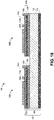
- Figure 16 illustrates two tiles 156A, 156B bonded to a single back portion 154 of the substrate 150 to produce the solar panel 100, according to an example.
- Each tile 156A, 156B can include a front portion 152A, 152B, a cell 160A, 160B, a first wire 170A, 170B, a second wire 172A, 172B, or a combination thereof.
- the tiles 156A, 156B can be positioned adjacent to one another (e.g., side-to-side or end-to-end) on the back portion 154 of the substrate 150.
- the tiles 156A, 156B can be connected together using the first wire(s) 170A, 170B, the second wire(s) 172A, 172B, or a combination thereof to form a string of tiles.
- the tiles 156A, 156B can instead be connected together using metal strips instead of wiring to form a string of tiles.
- the tiles 156A, 156B can be connected to form the string before the first wire(s) 170A, 170B is/are positioned within the channel(s) (e.g., as at step 324).
- the strings can be connected to the vehicle.
- Bonding the two or more tiles 156A, 156B to a single back portion 154 can make producing and repairing the solar panel 100 easier because it can facilitate automation and standardization.
- the handling of the components used to make the solar panel 100 can be easier because the tiles 156A, 156B can be smaller than those used to produce conventional solar panels.
- the back portion 154 of the substrate 150 can have a greater surface area than each of the tiles 156A, 156B.
- surface area of the back portion 154 of the substrate 150 is the same or about the same as the surface area of the two tiles 156A, 156B combined; however, in other examples, the back portion 154 of the substrate 150 can be sized to receive four tiles, six tiles, eight tiles, or more.
- the method 1300 also includes connecting the solar panel 100 to a vehicle, as at 1330. More particularly, the solar panel 100 can be connected to an exterior of the vehicle.
- the vehicle can be or include a car, a bus, a train, a boat, an airplane, a helicopter, an unmanned aerial vehicle (UAV), a spacecraft, or the like.
- UAV unmanned aerial vehicle
- FIG 17 illustrates an example of a vehicle 1700 to which the solar panel 100 can be coupled, according to an example.
- the vehicle 1700 can be or include a car, a bus, a train, a boat, an airplane, a helicopter, an unmanned aerial vehicle (UAV), a spacecraft, or the like.
- the vehicle 1700 is an aircraft (e.g., an airplane).
- the solar panel 100 can be coupled to an outer surface of the vehicle 1700.
- the solar panel 100 is coupled to the wing 1710; however, the solar panel 100 can also or instead be coupled to other portions of the vehicle 1700.
- the solar panel 100 can convert sunlight into energy, which can be supplied to the vehicle 1700 and/or the components therein (e.g., communication systems, lighting, etc.).
- the terms “inner” and “outer”; “up” and “down”; “upper” and “lower”; “upward” and “downward”; “upstream” and “downstream”; “above” and “below”; “inward” and “outward”; and other like terms as used herein refer to relative positions to one another and are not intended to denote a particular direction or spatial orientation.
- Couple refers to "in direct connection with” or “in connection with via one or more intermediate elements or members.”
- bonded refers to "directly bonded to” or “bonded to via one or more intermediate elements, members, or layers.”
- the term "at least one of A and B" with respect to a listing of items such as, for example, A and B, means A alone, B alone, or A and B.
- Those skilled in the art will recognize that these and other variations are possible.
- the terms “including,” “includes,” “having,” “has,” “with,” or variants thereof are used in either the detailed description and the claims, such terms are intended to be inclusive in a manner similar to the term “comprising.”
- the term “about” indicates that the value listed may be somewhat altered, as long as the alteration does not result in nonconformance of the process or structure to the intended purpose described herein.
- “exemplary” indicates the description is used as an example, rather than implying that it is an ideal.
Applications Claiming Priority (1)
| Application Number | Priority Date | Filing Date | Title |
|---|---|---|---|
| US16/878,469 US11791430B2 (en) | 2020-05-19 | 2020-05-19 | Solar panel and method for producing the solar panel |
Publications (1)
| Publication Number | Publication Date |
|---|---|
| EP3913688A1 true EP3913688A1 (fr) | 2021-11-24 |
Family
ID=76011771
Family Applications (1)
| Application Number | Title | Priority Date | Filing Date |
|---|---|---|---|
| EP21174635.9A Pending EP3913688A1 (fr) | 2020-05-19 | 2021-05-19 | Panneau solaire et procédé de production du panneau solaire |
Country Status (3)
| Country | Link |
|---|---|
| US (1) | US11791430B2 (fr) |
| EP (1) | EP3913688A1 (fr) |
| JP (1) | JP2022001011A (fr) |
Citations (4)
| Publication number | Priority date | Publication date | Assignee | Title |
|---|---|---|---|---|
| JPH1162146A (ja) * | 1997-08-20 | 1999-03-05 | Tomoji Sumiya | 屋根構造 |
| US20070074755A1 (en) * | 2005-10-03 | 2007-04-05 | Nanosolar, Inc. | Photovoltaic module with rigidizing backplane |
| JP2009032954A (ja) * | 2007-07-27 | 2009-02-12 | Fuji Electric Holdings Co Ltd | 太陽電池パネル及びその製造方法 |
| FR3043840A1 (fr) * | 2015-11-16 | 2017-05-19 | Commissariat Energie Atomique | Module photovoltaique leger comportant une couche avant en verre ou polymere et une couche arriere alveolaire |
Family Cites Families (8)
| Publication number | Priority date | Publication date | Assignee | Title |
|---|---|---|---|---|
| US6005184A (en) | 1997-07-11 | 1999-12-21 | Space Systems/Loral, Inc. | Solar panels having improved heat dissipation properties |
| EP1234926A1 (fr) * | 2001-02-21 | 2002-08-28 | Thyssen Bausysteme GmbH | Panneau en tôle thermiquement isolant avec élément photovoltaique, pour recouvrement de toiture ou de façade |
| US7592536B2 (en) | 2003-10-02 | 2009-09-22 | The Boeing Company | Solar cell structure with integrated discrete by-pass diode |
| WO2008112985A1 (fr) | 2007-03-14 | 2008-09-18 | Evergreen Solar, Inc. | Module solaire avec couche de raidissement |
| FR2946459B1 (fr) | 2009-06-05 | 2011-08-05 | Centre Nat Etd Spatiales | Element de structure pour panneau solaire, et structure comportant un tel element |
| JP6034569B2 (ja) | 2012-02-06 | 2016-11-30 | 日東電工株式会社 | 粘着シート、保護ユニットおよび太陽電池モジュール |
| CN110010713B (zh) * | 2013-02-25 | 2020-10-27 | 沙特基础工业全球技术有限公司 | 光伏模块组件 |
| US10276742B2 (en) | 2015-07-09 | 2019-04-30 | Solaero Technologies Corp. | Assembly and mounting of solar cells on space vehicles or satellites |
-
2020
- 2020-05-19 US US16/878,469 patent/US11791430B2/en active Active
-
2021
- 2021-05-18 JP JP2021083802A patent/JP2022001011A/ja active Pending
- 2021-05-19 EP EP21174635.9A patent/EP3913688A1/fr active Pending
Patent Citations (4)
| Publication number | Priority date | Publication date | Assignee | Title |
|---|---|---|---|---|
| JPH1162146A (ja) * | 1997-08-20 | 1999-03-05 | Tomoji Sumiya | 屋根構造 |
| US20070074755A1 (en) * | 2005-10-03 | 2007-04-05 | Nanosolar, Inc. | Photovoltaic module with rigidizing backplane |
| JP2009032954A (ja) * | 2007-07-27 | 2009-02-12 | Fuji Electric Holdings Co Ltd | 太陽電池パネル及びその製造方法 |
| FR3043840A1 (fr) * | 2015-11-16 | 2017-05-19 | Commissariat Energie Atomique | Module photovoltaique leger comportant une couche avant en verre ou polymere et une couche arriere alveolaire |
Non-Patent Citations (1)
| Title |
|---|
| SANKARAN ET AL: "On the development of solar arrays for INSAT 2A and 2B", PROCEEDINGS OF THE EUROPEAN SPACE POWER CONFERENCE, SN, SL, vol. 2, no. 4, 4 September 1995 (1995-09-04), pages 649 - 652, XP002116582 * |
Also Published As
| Publication number | Publication date |
|---|---|
| US20210367089A1 (en) | 2021-11-25 |
| JP2022001011A (ja) | 2022-01-04 |
| US11791430B2 (en) | 2023-10-17 |
Similar Documents
| Publication | Publication Date | Title |
|---|---|---|
| US8617687B2 (en) | Multi-functional aircraft structures | |
| CA2955325C (fr) | Spaghettiere superposee pour un rappel a grande capacite destinee a un longeron composite | |
| US8763253B2 (en) | Vertical laminate noodle for high capacity pull-off for a composite stringer | |
| JP5808379B2 (ja) | 複合材翼のための継手 | |
| US8517312B2 (en) | Multi-spar port box joint | |
| CA2783109C (fr) | Fibre laminee verticale pour retrait haute capacite d'un element composite lisse | |
| EP3329521B1 (fr) | Système générateur solaire et procédé de fabrication | |
| EP3441300B1 (fr) | Système de cloison de pressurisation | |
| EA032589B1 (ru) | Узел батареи, удерживающее устройство для батареи и соответствующие способы изготовления | |
| EP3913688A1 (fr) | Panneau solaire et procédé de production du panneau solaire | |
| EP3913689A1 (fr) | Panneau solaire et procédé de production du panneau solaire | |
| EP3210769A1 (fr) | Procédés de réparation d'un panneau sandwich acoustique et kits de réparation de panneau sandwich acoustique associés | |
| JP7356821B2 (ja) | 垂直補強材の共硬化方法 | |
| EP3231586B1 (fr) | Structure dotée de structures unitaires assemblées | |
| US10752336B2 (en) | Composite support structures for composite integrated structure | |
| KR100271064B1 (ko) | 복합재 항공기 날개용 치공구 제작방법 및 이를 이용한 복합재 항공기 날개 제작방법 | |
| GB2617616A (en) | Method of repairing a composite beam | |
| Alexander et al. | Manufacturing Methods and Technology (MANTECH) Program Manufacturing Techniques for a Composite Tail Section for the Advanced Attack Helicopter. |
Legal Events
| Date | Code | Title | Description |
|---|---|---|---|
| PUAI | Public reference made under article 153(3) epc to a published international application that has entered the european phase |
Free format text: ORIGINAL CODE: 0009012 |
|
| STAA | Information on the status of an ep patent application or granted ep patent |
Free format text: STATUS: THE APPLICATION HAS BEEN PUBLISHED |
|
| AK | Designated contracting states |
Kind code of ref document: A1 Designated state(s): AL AT BE BG CH CY CZ DE DK EE ES FI FR GB GR HR HU IE IS IT LI LT LU LV MC MK MT NL NO PL PT RO RS SE SI SK SM TR |
|
| B565 | Issuance of search results under rule 164(2) epc |
Effective date: 20210903 |
|
| STAA | Information on the status of an ep patent application or granted ep patent |
Free format text: STATUS: REQUEST FOR EXAMINATION WAS MADE |
|
| 17P | Request for examination filed |
Effective date: 20220511 |
|
| RBV | Designated contracting states (corrected) |
Designated state(s): AL AT BE BG CH CY CZ DE DK EE ES FI FR GB GR HR HU IE IS IT LI LT LU LV MC MK MT NL NO PL PT RO RS SE SI SK SM TR |
|
| RAP3 | Party data changed (applicant data changed or rights of an application transferred) |
Owner name: THE BOEING COMPANY |