EP3913654A1 - Axial alignment assembly, and charged particle microscope comprising such an alignment assembly - Google Patents
Axial alignment assembly, and charged particle microscope comprising such an alignment assembly Download PDFInfo
- Publication number
- EP3913654A1 EP3913654A1 EP20175865.3A EP20175865A EP3913654A1 EP 3913654 A1 EP3913654 A1 EP 3913654A1 EP 20175865 A EP20175865 A EP 20175865A EP 3913654 A1 EP3913654 A1 EP 3913654A1
- Authority
- EP
- European Patent Office
- Prior art keywords
- resilient elements
- jacket
- axial alignment
- outer jacket
- alignment assembly
- Prior art date
- Legal status (The legal status is an assumption and is not a legal conclusion. Google has not performed a legal analysis and makes no representation as to the accuracy of the status listed.)
- Pending
Links
- 239000002245 particle Substances 0.000 title claims description 21
- 238000000034 method Methods 0.000 claims description 13
- 239000004033 plastic Substances 0.000 claims description 5
- 239000000463 material Substances 0.000 claims description 2
- 238000003384 imaging method Methods 0.000 description 9
- 230000004907 flux Effects 0.000 description 6
- 229910052751 metal Inorganic materials 0.000 description 6
- 239000002184 metal Substances 0.000 description 6
- 230000005855 radiation Effects 0.000 description 5
- 230000006835 compression Effects 0.000 description 4
- 238000007906 compression Methods 0.000 description 4
- 238000010894 electron beam technology Methods 0.000 description 4
- 230000033001 locomotion Effects 0.000 description 4
- 230000003287 optical effect Effects 0.000 description 4
- 238000004458 analytical method Methods 0.000 description 3
- 238000002591 computed tomography Methods 0.000 description 3
- 238000002149 energy-dispersive X-ray emission spectroscopy Methods 0.000 description 3
- 230000005540 biological transmission Effects 0.000 description 2
- 238000005136 cathodoluminescence Methods 0.000 description 2
- 230000000694 effects Effects 0.000 description 2
- 238000010884 ion-beam technique Methods 0.000 description 2
- 238000000386 microscopy Methods 0.000 description 2
- 241000894007 species Species 0.000 description 2
- 241000252073 Anguilliformes Species 0.000 description 1
- 229930040373 Paraformaldehyde Natural products 0.000 description 1
- 230000000712 assembly Effects 0.000 description 1
- 238000000429 assembly Methods 0.000 description 1
- 239000002131 composite material Substances 0.000 description 1
- 238000001816 cooling Methods 0.000 description 1
- 230000008021 deposition Effects 0.000 description 1
- 238000001514 detection method Methods 0.000 description 1
- 238000005430 electron energy loss spectroscopy Methods 0.000 description 1
- 238000001493 electron microscopy Methods 0.000 description 1
- 230000007613 environmental effect Effects 0.000 description 1
- 230000003993 interaction Effects 0.000 description 1
- 238000003754 machining Methods 0.000 description 1
- 238000004519 manufacturing process Methods 0.000 description 1
- 239000011159 matrix material Substances 0.000 description 1
- 238000005259 measurement Methods 0.000 description 1
- 230000007246 mechanism Effects 0.000 description 1
- 150000002739 metals Chemical class 0.000 description 1
- 238000003801 milling Methods 0.000 description 1
- 230000000149 penetrating effect Effects 0.000 description 1
- -1 polyoxymethylene Polymers 0.000 description 1
- 229920006324 polyoxymethylene Polymers 0.000 description 1
- 239000002244 precipitate Substances 0.000 description 1
- 238000009417 prefabrication Methods 0.000 description 1
- 238000003825 pressing Methods 0.000 description 1
- 239000007787 solid Substances 0.000 description 1
- 230000003068 static effect Effects 0.000 description 1
- 230000003319 supportive effect Effects 0.000 description 1
- 238000004804 winding Methods 0.000 description 1
Images



Classifications
-
- H—ELECTRICITY
- H01—ELECTRIC ELEMENTS
- H01J—ELECTRIC DISCHARGE TUBES OR DISCHARGE LAMPS
- H01J37/00—Discharge tubes with provision for introducing objects or material to be exposed to the discharge, e.g. for the purpose of examination or processing thereof
- H01J37/02—Details
- H01J37/04—Arrangements of electrodes and associated parts for generating or controlling the discharge, e.g. electron-optical arrangement or ion-optical arrangement
-
- H—ELECTRICITY
- H01—ELECTRIC ELEMENTS
- H01J—ELECTRIC DISCHARGE TUBES OR DISCHARGE LAMPS
- H01J37/00—Discharge tubes with provision for introducing objects or material to be exposed to the discharge, e.g. for the purpose of examination or processing thereof
- H01J37/02—Details
- H01J37/20—Means for supporting or positioning the object or the material; Means for adjusting diaphragms or lenses associated with the support
-
- F—MECHANICAL ENGINEERING; LIGHTING; HEATING; WEAPONS; BLASTING
- F16—ENGINEERING ELEMENTS AND UNITS; GENERAL MEASURES FOR PRODUCING AND MAINTAINING EFFECTIVE FUNCTIONING OF MACHINES OR INSTALLATIONS; THERMAL INSULATION IN GENERAL
- F16C—SHAFTS; FLEXIBLE SHAFTS; ELEMENTS OR CRANKSHAFT MECHANISMS; ROTARY BODIES OTHER THAN GEARING ELEMENTS; BEARINGS
- F16C33/00—Parts of bearings; Special methods for making bearings or parts thereof
- F16C33/72—Sealings
- F16C33/76—Sealings of ball or roller bearings
- F16C33/768—Sealings of ball or roller bearings between relatively stationary parts, i.e. static seals
-
- F—MECHANICAL ENGINEERING; LIGHTING; HEATING; WEAPONS; BLASTING
- F16—ENGINEERING ELEMENTS AND UNITS; GENERAL MEASURES FOR PRODUCING AND MAINTAINING EFFECTIVE FUNCTIONING OF MACHINES OR INSTALLATIONS; THERMAL INSULATION IN GENERAL
- F16C—SHAFTS; FLEXIBLE SHAFTS; ELEMENTS OR CRANKSHAFT MECHANISMS; ROTARY BODIES OTHER THAN GEARING ELEMENTS; BEARINGS
- F16C33/00—Parts of bearings; Special methods for making bearings or parts thereof
- F16C33/72—Sealings
- F16C33/76—Sealings of ball or roller bearings
- F16C33/761—Sealings of ball or roller bearings specifically for bearings with purely axial load
-
- H—ELECTRICITY
- H01—ELECTRIC ELEMENTS
- H01J—ELECTRIC DISCHARGE TUBES OR DISCHARGE LAMPS
- H01J37/00—Discharge tubes with provision for introducing objects or material to be exposed to the discharge, e.g. for the purpose of examination or processing thereof
- H01J37/02—Details
- H01J37/04—Arrangements of electrodes and associated parts for generating or controlling the discharge, e.g. electron-optical arrangement or ion-optical arrangement
- H01J37/10—Lenses
- H01J37/14—Lenses magnetic
- H01J37/141—Electromagnetic lenses
- H01J37/1413—Means for interchanging parts of the lens, e. g. pole pieces within the tube
-
- H—ELECTRICITY
- H01—ELECTRIC ELEMENTS
- H01J—ELECTRIC DISCHARGE TUBES OR DISCHARGE LAMPS
- H01J37/00—Discharge tubes with provision for introducing objects or material to be exposed to the discharge, e.g. for the purpose of examination or processing thereof
- H01J37/02—Details
- H01J37/04—Arrangements of electrodes and associated parts for generating or controlling the discharge, e.g. electron-optical arrangement or ion-optical arrangement
- H01J37/147—Arrangements for directing or deflecting the discharge along a desired path
- H01J37/15—External mechanical adjustment of electron or ion optical components
-
- H—ELECTRICITY
- H01—ELECTRIC ELEMENTS
- H01J—ELECTRIC DISCHARGE TUBES OR DISCHARGE LAMPS
- H01J37/00—Discharge tubes with provision for introducing objects or material to be exposed to the discharge, e.g. for the purpose of examination or processing thereof
- H01J37/02—Details
- H01J37/16—Vessels; Containers
-
- H—ELECTRICITY
- H01—ELECTRIC ELEMENTS
- H01J—ELECTRIC DISCHARGE TUBES OR DISCHARGE LAMPS
- H01J37/00—Discharge tubes with provision for introducing objects or material to be exposed to the discharge, e.g. for the purpose of examination or processing thereof
- H01J37/26—Electron or ion microscopes; Electron or ion diffraction tubes
-
- H—ELECTRICITY
- H01—ELECTRIC ELEMENTS
- H01J—ELECTRIC DISCHARGE TUBES OR DISCHARGE LAMPS
- H01J2237/00—Discharge tubes exposing object to beam, e.g. for analysis treatment, etching, imaging
- H01J2237/03—Mounting, supporting, spacing or insulating electrodes
- H01J2237/032—Mounting or supporting
-
- H—ELECTRICITY
- H01—ELECTRIC ELEMENTS
- H01J—ELECTRIC DISCHARGE TUBES OR DISCHARGE LAMPS
- H01J2237/00—Discharge tubes exposing object to beam, e.g. for analysis treatment, etching, imaging
- H01J2237/10—Lenses
- H01J2237/14—Lenses magnetic
- H01J2237/1405—Constructional details
- H01J2237/1415—Bores or yokes, i.e. magnetic circuit in general
-
- H—ELECTRICITY
- H01—ELECTRIC ELEMENTS
- H01J—ELECTRIC DISCHARGE TUBES OR DISCHARGE LAMPS
- H01J2237/00—Discharge tubes exposing object to beam, e.g. for analysis treatment, etching, imaging
- H01J2237/16—Vessels
Definitions
- the invention relates to an axial alignment assembly, comprising a first body with a first axial alignment axis, and a second body having a second axial alignment axis, and wherein the axial alignment assembly is arranged for aligning said first and second axial alignment axis substantially onto each other.
- the invention also relates to a charged particle microscope comprising such an axial alignment assembly.
- Charged particle microscopy is a well-known and increasingly important technique for imaging microscopic objects, particularly in the form of electron microscopy.
- the basic genus of electron microscope has undergone evolution into a number of well-known apparatus species, such as the Transmission Electron Microscope (TEM), Scanning Electron Microscope (SEM), and Scanning Transmission Electron Microscope (STEM), and also into various sub-species, such as so-called “dual-beam” apparatus (e.g. a FIB-SEM), which additionally employ a "machining" Focused Ion Beam (FIB), allowing supportive activities such as ion-beam milling or lon-Beam-Induced Deposition (IBID), for example.
- TEM Transmission Electron Microscope
- SEM Scanning Electron Microscope
- STEM Scanning Transmission Electron Microscope
- STEM Scanning Transmission Electron Microscope
- FIB-SEM dual-beam apparatus
- FIB Focused Ion Beam
- irradiation of a sample by a scanning electron beam precipitates emanation of "auxiliary" radiation from the sample, in the form of secondary electrons, backscattered electrons, X-rays and cathodoluminescence (infrared, visible and/or ultraviolet photons).
- auxiliary radiation in the form of secondary electrons, backscattered electrons, X-rays and cathodoluminescence (infrared, visible and/or ultraviolet photons).
- auxiliary radiation in the form of secondary electrons, backscattered electrons, X-rays and cathodoluminescence (infrared, visible and/or ultraviolet photons).
- X-rays infrared, visible and/or ultraviolet photons
- a beam of electrons is transmitted through a specimen to form an image from the interaction of the electrons with the sample as the beam is transmitted through the specimen.
- the image is then magnified and focused onto an imaging device, such as a fluorescent screen, a layer of photographic film, or a sensor such as a scintillator attached to a charge-coupled device (CCD).
- the scintillator converts primary electrons in the microscope to photons so that the CCD is able to detect it.
- Charged particle microscopes comprise a number of modules that need to be accurately aligned with respect to a common axial alignment axis.
- This common axial alignment axis often is the electron-optical axis.
- the modules that need to be accurately aligned include optical modules, such electromagnetic lenses, in particular pole pieces of these electromagnetic lenses.
- the required tolerance for aligning an upper pole piece and a lower pole piece may be in the order of magnitude of 1 ⁇ m. These strict tolerances are sometimes required in other mechanical systems as well.
- an axial alignment assembly is provided as defined in claim 1.
- the axial alignment assembly as defined herein comprises a first body comprising a substantially cylindrical outer jacket.
- the first body comprises a first alignment axis.
- the first alignment axis generally corresponds to the longitudinal axis of the cylinder defined by said cylindrical outer jacket.
- the first body may, for example, be an optical module of a charged particle microscope, such as a pole piece of an electromagnetic lens.
- the first body may comprise a hollow bore that is centered with respect to the first alignment axis. Other embodiments of the first body are conceivable as well of course.
- the axial alignment assembly comprises a second body that comprises a substantially cylindrical inner jacket.
- the second body comprises a second alignment axis.
- the second alignment axis generally corresponds to the longitudinal axis of the (virtual) cylinder defined by said cylindrical inner jacket.
- Said second body is positioned with respect to said first body in such a way that said inner jacket of said first body faces said outer jacket of said second body.
- the first body is at least partly positioned within a cylindrical gap defined by said virtual cylinder.
- the size and dimensions of the first body and the size and dimensions of the cylindrical gap are such that an annular recess is formed in between said inner jacket and said outer jacket.
- a substantially annular recess is formed in between said inner jacket and said outer jacket.
- Said recess may have a nominal width of at least a few dozen millimeters, or even a few dozen micrometers.
- the axial alignment assembly as defined herein also comprises a plurality of resilient elements that are positioned within said annular recess.
- These resilient elements may in principle have any geometry as long as at least one dimension of these resilient elements exceeds the nominal size of the annular recess.
- the resilient elements are substantially spherical, wherein a diameter of the spherical resilient elements exceeds the nominal size, i.e. the distance between the inner jacket and the outer jacket, of the annular recess.
- each of the plurality of resilient elements is in contact with said outer jacket of said first body and with said inner jacket of said second body. The resilient elements exert a force onto said outer jacket and onto said inner jacket, and due to this the first alignment axis and said second alignment axis are aligned, thus aligning the first body with the second body.
- resilient elements in an annular recess formed by an outer cylindrical jacket and an inner cylindrical jacket ensures a good centering, i.e. axial alignment, of the two bodies despite of large dimension and geometry deviations that may occur in the two bodies and the resilient elements.
- an axial alignment assembly that uses plastic balls is known from NL10257037C in name of applicant.
- two bodies that need to be aligned are provided with corresponding V-shaped annular grooves.
- the two bodies are directed to each other in such a way that the V-shaped annular grooves of the two bodies form a substantially rectangular annular groove having four abutment surfaces.
- this V-groove design requires the two bodies to be 'pulled together'.
- the two bodies need to be fixed to each other, and the plastic balls need to be squeezed onto the four abutment surfaces for the alignment assembly to be able to work.
- the clamping force to deform the balls is considerable.
- One option to reduce the clamping force is to use "softer" balls, i.e. balls that can be compressed more easily, but this has as a negative side effect that it also decrease the force that is used to align the two bodies.
- the outer jacket and the inner jacket for forming an annular recess in which the resilient elements are provided.
- This has advantages over the alignment assembly as described in NL10257037C , as the axial alignment assembly according to the present invention does not require the presence of four abutment surfaces, and does not require the use of an axial clamping force. With this, an improved axial alignment assembly is provided that additionally is able to provide tolerances of about 1 ⁇ m. With this, the object of the invention is achieved.
- the resilient elements comprise substantially spherical elements.
- spherical elements By using spherical elements, the need to orient the resilient elements in the right way is alleviated, in particular in case the spherical resilient elements have substantially isotropic resiliency properties.
- the spherical elements can be produced with good dimension tolerances. Additionally, the use of a spherical element allows the resilient elements to roll within the annular recess, leading to minimal (down to zero) tangential residual forces on the resilient elements, which aids in the axial alignment properties.
- the dimension and the number of resilient elements is adapted to the diameter of the outer jacket of the first body.
- the number of resilient elements is as high as possible, but the dimension of the resilient element should not be too small as this increases the required tolerances for all components (first body, second body and resilient elements).
- the dimension of the resilient element may be in the range of 1% to 10% of the radius of the first body, and preferably at approximately 5%. This ratio ensures that approximately 125 resilient elements can be fitted about the outer cylindrical jacket of the first body.
- a coil spring is provided with windings that make up the resilient elements.
- the coil spring may provide a way of easier assembly of the axial alignment assembly as fewer parts need to be installed.
- the resilient elements are composed of a plastic material, such as polyoxymethylene.
- a plastic material such as polyoxymethylene.
- rubber elements could be used as well.
- the first body has a first abutting surface
- the second body has a second abutting surface that is connected to said first abutting surface in a connected state of the axial alignment assembly.
- the first abutting surface comprises a normal that may be directed substantially parallel to the first alignment axis.
- the second abutting surface comprises a normal that may be directed substantially parallel to the second alignment axis.
- the normal of the first body and the normal of the second body are directed in opposite directions.
- At least one of the first abutting surface and the second abutting surface has a surface normal with a component parallel to said first alignment axis and/or second alignment axis.
- the first abutting surface may be substantially orthogonal with respect to the outer cylindrical jacket of the first body.
- the second abutting surface may be substantially orthogonal with respect to the cylindrical inner jacket.
- at least one of the first abutting surface and the second abutting surface is positioned orthogonal with respect to the outer jacket and/or inner jacket.
- the axial alignment assembly comprises a holder for holding the plurality of resilient elements.
- the holder can be provided in the recess that is formed in between the outer cylindrical jacket and the inner cylindrical jacket.
- the holder enables effective manufacturing of the axial assembly, as it allows prefabrication of the holder with the plurality of resilient elements.
- the holder with resilient elements may then be inserted in between the first body and the second body.
- the holder can be placed next to the inner cylindrical jacket of the second body, and the first body can be positioned in place.
- the holder comprises a cage for enclosing said resilient elements, in particular in a direction parallel to said alignment axis.
- a charged particle microscope comprising an axial alignment assembly as defined herein.
- said first body is a pole piece of a lens.
- a method of axially aligning a first body and a second body comprises the steps of:
- first body, second body and resilient elements may include:
- the method comprises the step of providing a holder for holding said plurality of resilient elements, and positioning said plurality of resilient elements in said holder.
- the step of providing a holder can be done in a number of ways.
- the plurality of resilient elements is positioned in said holder before the combination of holder and resilient elements is brought into contact with either one of the first body or the second body.
- said plurality of resilient elements is brought into contact with one of the outer jacket and the inner jacket first, and into contact with the other one of the outer jacket and the inner jacket later.
- the method may comprise the step of moving said first body relative to said second body in a direction mainly parallel to said first and second alignment axis.
- Fig. 1 (not to scale) is a highly schematic depiction of an embodiment of a charged-particle microscope M according to an embodiment of the invention. More specifically, it shows an embodiment of a transmission-type microscope M, which, in this case, is a TEM/STEM (though, in the context of the current invention, it could just as validly be a SEM (see Figure 2 ), or an ion-based microscope, for example).
- a transmission-type microscope M which, in this case, is a TEM/STEM (though, in the context of the current invention, it could just as validly be a SEM (see Figure 2 ), or an ion-based microscope, for example).
- an electron source 4 produces a beam B of electrons that propagates along an electron-optical axis B' and traverses an electron-optical illuminator 6, serving to direct/focus the electrons onto a chosen part of a specimen S (which may, for example, be (locally) thinned/planarized).
- a deflector 8 which ( inter alia ) can be used to effect scanning motion of the beam B.
- the specimen S is held on a specimen holder H that can be positioned in multiple degrees of freedom by a positioning device / stage A, which moves a cradle A' into which holder H is (removably) affixed; for example, the specimen holder H may comprise a finger that can be moved ( inter alia ) in the XY plane (see the depicted Cartesian coordinate system; typically, motion parallel to Z and tilt about X/Y will also be possible). Such movement allows different parts of the specimen S to be illuminated / imaged / inspected by the electron beam B traveling along axis B' (in the Z direction) (and/or allows scanning motion to be performed, as an alternative to beam scanning).
- an optional cooling device (not depicted) can be brought into intimate thermal contact with the specimen holder H, so as to maintain it (and the specimen S thereupon) at cryogenic temperatures, for example.
- the electron beam B will interact with the specimen S in such a manner as to cause various types of "stimulated” radiation to emanate from the specimen S, including (for example) secondary electrons, backscattered electrons, X-rays and optical radiation (cathodoluminescence).
- various types of "stimulated" radiation including (for example) secondary electrons, backscattered electrons, X-rays and optical radiation (cathodoluminescence).
- one or more of these radiation types can be detected with the aid of analysis device 22, which might be a combined scintillator/photomultiplier or EDX or EDS (Energy-Dispersive X-Ray Spectroscopy) module, for instance; in such a case, an image could be constructed using basically the same principle as in a SEM.
- an imaging system projection lens 24 which will generally comprise a variety of electrostatic / magnetic lenses, deflectors, correctors (such as stigmators), etc.
- this imaging system 24 can focus the transmitted electron flux onto a fluorescent screen 26, which, if desired, can be retracted/withdrawn (as schematically indicated by arrows 26') so as to get it out of the way of axis B'.
- An image (or diffractogram) of (part of) the specimen S will be formed by imaging system 24 on screen 26, and this may be viewed through viewing port 28 located in a suitable part of a wall of enclosure 2.
- the retraction mechanism for screen 26 may, for example, be mechanical and/or electrical in nature, and is not depicted here.
- spectroscopic apparatus 34 can also be integrated into the imaging system 24.
- the microscope M further comprises a retractable X-ray Computed Tomography (CT) module, generally indicated by reference 40.
- CT Computed Tomography
- the source and (diametrically opposed) detector are used to look through the specimen along different lines of sight, so as to acquire penetrative observations of the specimen from a variety of perspectives.
- controller 20 is connected to various illustrated components via control lines (buses) 20'.
- This controller 20 can provide a variety of functions, such as synchronizing actions, providing setpoints, processing signals, performing calculations, and displaying messages/information on a display device (not depicted).
- the (schematically depicted) controller 20 may be (partially) inside or outside the enclosure 2, and may have a unitary or composite structure, as desired.
- the interior of the enclosure 2 does not have to be kept at a strict vacuum; for example, in a so-called "Environmental TEM/STEM", a background atmosphere of a given gas is deliberately introduced / maintained within the enclosure 2.
- the skilled artisan will also understand that, in practice, it may be advantageous to confine the volume of enclosure 2 so that, where possible, it essentially hugs the axis B', taking the form of a small tube ( e.g. of the order of 1 cm in diameter) through which the employed electron beam passes, but widening out to accommodate structures such as the source 4, specimen holder H, screen 26, camera 30, camera 32, spectroscopic apparatus 34, etc.
- FIG. 2 is a highly schematic depiction of a charged-particle microscope M according to the present invention; more specifically, it shows an embodiment of a non-transmission-type microscope M, which, in this case, is a SEM (though, in the context of the current invention, it could just as validly be an ion-based microscope, for example).
- a SEM though, in the context of the current invention, it could just as validly be an ion-based microscope, for example.
- parts which correspond to items in Figure 1 are indicated using identical reference symbols, and will not be separately discussed here. Additional to Figure 1 are ( inter alia ) the following parts:
- Fig. 1 and Fig. 2 need to be axially aligned. But in general, it may be required that two or more components need to be axially aligned. To this end, the disclosure provides an axial alignment assembly.
- Fig. 3 it is shown an assembly 100 of a first substantially cylindrical body 101 having a first axial alignment axis A1, and a second substantially cylindrical body 201 having a second axial alignment axis A2.
- the first body 101 and the second body 201 do not necessarily have to be cylindrical.
- the first body 101 comprises a substantially cylindrical outer jacket 103, and having a first alignment axis A1.
- the first body 101 may have, as shown in Fig. 3 , a central bore 104, although in view of the present disclosure a first body that is substantially solid is conceivable as well.
- the second body 201 as defined herein comprised a substantially cylindrical inner jacket 203, and has a second alignment axis A2.
- the second body 201 has, in the embodiment shown, an annular protrusion 202 that extends towards the second alignment axis A2.
- This annular protrusion 202 allows the first body 101 to rest onto the protrusion of the second body 201, as will be explained in more detail with respect to Fig. 4b .
- the second body 201 is positioned with respect to said first body 101 in such a way that said inner jacket 203 faces said outer jacket 103.
- a substantially annular recess 401 is formed in between said inner jacket 103 and said outer jacket 203 a substantially annular recess 401 is formed.
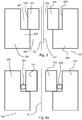
- the first axis A1 is misaligned with respect to the second axis A2.
- the dimensions of the annular recess are smaller on the right-hand-side of the Fig. 3 ; and are slightly wider on the left-hand-side of Fig. 3 . Alignment of these two bodies poses a challenge.
- the first body 101 and the second body 201 can be aligned with respect to their alignment axes A1, A2, by providing a plurality of resilient elements 301, 302 that are positioned within said annular recess 401.
- Each of the plurality of resilient elements 301, 302 is in contact with said outer jacket 103 of said first body 101 and with said inner jacket 203 of said second body 201.
- the resilient elements 301, 302, and the first body 101 and the second body 201 are shaped in such a way that each of the resilient elements 301, 302 exerts a force onto said outer jacket 103 and onto said inner jacket 203 for aligning said first alignment axis A1 and said second alignment axis A2.
- the annular recess 401 is smaller on the right-hand-side of the drawing.
- the annular recess 401 is larger on the left-hand-side of the drawings.
- the resilient elements 302 in the more narrow part of the recess 401 will thus exert a greater force onto the cylindrical jackets 103, 203 compared to the resilient elements 301 in the more wider part of the recess 401.
- the resulting force will push the first body 101 away from the second body 201 in a direction to the more wider part.
- the more narrow part of the recess will become wider, and the more wider part will become more narrower.
- This balance of forces will continue until the alignment axis A1 of the first body 101 is substantially aligned with the alignment axis A2 of the second body 201, and the alignment axes coincide into a single aligned axis A (as shown in Fig. 4a ).
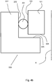
- Fig. 4b shows a detail of the axial alignment assembly 100 as shown in Fig. 4a .
- the first body 101 has a first abutment surface 105
- the second body 201 has a second abutment surface 205.
- the first abutment surface 105 and the second abutment surface 205 are mainly parallel to each other.
- the first abutment surface 105 and the second abutment surface 205 are mainly orthogonal with respect to the corresponding inner/outer jacket 103, 203 of the first and second body 101, 201.
- the axial alignment assembly as defined herein does not require an axial compression force to be exerted onto the first body 101 and the second body 201.
- the axial alignment forces is established by the dimensioning of the outer jacket 103, the inner jacket 203, and the resilient elements 301.
- axial alignment assembly 100 as defined herein is explained with respect to cylindrical bodies and an annular recess. It is noted that instead of cylindrical bodies, other orders of rotational symmetry could be applied in the axial alignment assembly as defined herein. For example, triangle, square, polygonal and other shapes are within the scope of the present disclosure, and are considered to be equivalents to the cylindrical bodies described above. In these instances, spherical resilient elements can be used. Applicant reserves the right to file one or more divisionals on these aspects.
- embodiments disclose the use of spherical resilient elements. These are advantageous as they do not need to be aligned in a specific way in order for the elements to work. Other shapes, however, are conceivable as well.
- abutment surfaces 105, 205 can be made into contact in a direct manner.
- a seal element (not shown) can be provided in between the first body 101 and the second body 201, such that the abutment surface 105 of the first body 101 comes into contact with a first side of the seal element, and the abutment surface 205 of the second body 201 comes into contact with the other, second side of the seal element.
- the seal element may be relatively thin, and can ensure a pressure seal between the inner part of the assembly (located closer to the central axis A) and a part located radially outside of the first body.
- the seal element can be made of rubber.
- the seal element can be made of a metal. This is advantageous in case the inner part of the axial alignment assembly (i.e. a space located close to the central axis A) is desired to have a very low pressure, such as a (near) vacuum.
- the metal seal element is thus able to provide a vacuum seal in the axial alignment assembly as defined herein. This is advantageous when used in charged particle microscopes, as will be explained later.
- FIG. 5 an alternative embodiment of the axial alignment assembly 100 is shown. It is noted that corresponding elements are identified using corresponding reference signs.
- the main difference with respect to the axial alignment assembly as shown in Fig. 4a is the use of a holder 311 for holding the resilient elements 301, 302 in place.
- the holder 311 may be prepared before assembly of the two bodies 101, 201, by adding the resilient elements 301, 302 to the holder 311.
- the holder 311 may be a cage for holding spherical resilient elements 301, 302. Other embodiments of holders 311 are conceivable as well.
- Fig. 6 shows an embodiment of a part of a charged particle microscope that uses an assembly as defined herein to align a total of three bodies 1101, 1102, 201.
- the most important alignment is considered to be the alignment of the upper body 1101 and the lower body 1102.
- the upper body 1101 and the lower body 1102 are, in the embodiment shown in Fig. 6 , an upper pole piece 1101 and a lower pole piece 1102, respectively, of a lens for a charged particle microscope, such as a charged particle microscope as shown in Fig. 1 or Fig. 2 .
- the axial alignment assembly 100 as defined herein provides an excellent way of aligning the upper 1101 and lower objective pole 1102 of a TEM.
- the required alignment of the upper and lower objective pole piece is in the order of magnitude 1 ⁇ m, and this is achievable with the axial alignment assembly as shown in Fig. 6 .
- the upper body 1101 is axially aligned with respect to the outer body 201 by using spherical resilient elements 301 in an upper annular recess; and the lower body 1102 is axially aligned with respect to the outer body 201 by using spherical resilient elements 401 in a lower annular recess.
- the resilient elements 301, 401 may be provided in a respective holder 311, 411, such as a cage, as shown in Fig. 6 .
- Measurements made on the axial alignment assembly as defined herein show that a concentricity of a few microns can be achieved in a relatively easy manner.
- the axial alignment assembly as defined herein can be used to provide UltraHighVacuum (UHV) specimen chambers.
- UHV UltraHighVacuum
- the axial alignment assembly as known from the prior requires the two bodies to be forced towards each other for the axial alignment to be able to take place. Using metal seals would significantly increase the axial compression force needed to obtain the desired axial alignment.
- the axial alignment assembly as defined herein does not require the use of an axial force to obtain the axial alignment, and thus allows the use of metal seals.
- Using the axial alignment assembly as defined herein for example with a ball array in a cylindrical gap will not hinder compression of a metal seal between e.g. the pole piece 1101, 1102 and the 'inner objective block' 201. With this, an UHV specimen chamber in a charged particle microscope can be obtained.
Landscapes
- Chemical & Material Sciences (AREA)
- Analytical Chemistry (AREA)
- Engineering & Computer Science (AREA)
- General Engineering & Computer Science (AREA)
- Mechanical Engineering (AREA)
- Physics & Mathematics (AREA)
- Electromagnetism (AREA)
- Analysing Materials By The Use Of Radiation (AREA)
Abstract
Description
- The invention relates to an axial alignment assembly, comprising a first body with a first axial alignment axis, and a second body having a second axial alignment axis, and wherein the axial alignment assembly is arranged for aligning said first and second axial alignment axis substantially onto each other.
- The invention also relates to a charged particle microscope comprising such an axial alignment assembly.
- Charged particle microscopy is a well-known and increasingly important technique for imaging microscopic objects, particularly in the form of electron microscopy. Historically, the basic genus of electron microscope has undergone evolution into a number of well-known apparatus species, such as the Transmission Electron Microscope (TEM), Scanning Electron Microscope (SEM), and Scanning Transmission Electron Microscope (STEM), and also into various sub-species, such as so-called "dual-beam" apparatus (e.g. a FIB-SEM), which additionally employ a "machining" Focused Ion Beam (FIB), allowing supportive activities such as ion-beam milling or lon-Beam-Induced Deposition (IBID), for example. The skilled person will be familiar with the different species of charged particle microscopy.
- In a SEM, irradiation of a sample by a scanning electron beam precipitates emanation of "auxiliary" radiation from the sample, in the form of secondary electrons, backscattered electrons, X-rays and cathodoluminescence (infrared, visible and/or ultraviolet photons). One or more components of this emanating radiation may be detected and used for sample analysis.
- In TEM, a beam of electrons is transmitted through a specimen to form an image from the interaction of the electrons with the sample as the beam is transmitted through the specimen. The image is then magnified and focused onto an imaging device, such as a fluorescent screen, a layer of photographic film, or a sensor such as a scintillator attached to a charge-coupled device (CCD). The scintillator converts primary electrons in the microscope to photons so that the CCD is able to detect it.
- Charged particle microscopes comprise a number of modules that need to be accurately aligned with respect to a common axial alignment axis. This common axial alignment axis often is the electron-optical axis. The modules that need to be accurately aligned include optical modules, such electromagnetic lenses, in particular pole pieces of these electromagnetic lenses. The required tolerance for aligning an upper pole piece and a lower pole piece, for example, may be in the order of magnitude of 1 µm. These strict tolerances are sometimes required in other mechanical systems as well.
- It is an object of the present disclosure to provide an axial alignment assembly that provides these required tolerances, or at least improves existing axial alignment assemblies. In particular, it is an object to provide an improved charged particle microscope by incorporating such an axial alignment assembly.
- To this end, an axial alignment assembly is provided as defined in claim 1.
- The axial alignment assembly as defined herein comprises a first body comprising a substantially cylindrical outer jacket. The first body comprises a first alignment axis. The first alignment axis generally corresponds to the longitudinal axis of the cylinder defined by said cylindrical outer jacket. The first body may, for example, be an optical module of a charged particle microscope, such as a pole piece of an electromagnetic lens. The first body may comprise a hollow bore that is centered with respect to the first alignment axis. Other embodiments of the first body are conceivable as well of course.
- As defined herein, the axial alignment assembly comprises a second body that comprises a substantially cylindrical inner jacket. The second body comprises a second alignment axis. The second alignment axis generally corresponds to the longitudinal axis of the (virtual) cylinder defined by said cylindrical inner jacket. Said second body is positioned with respect to said first body in such a way that said inner jacket of said first body faces said outer jacket of said second body. In other words, the first body is at least partly positioned within a cylindrical gap defined by said virtual cylinder. The size and dimensions of the first body and the size and dimensions of the cylindrical gap are such that an annular recess is formed in between said inner jacket and said outer jacket. Hence, in between said inner jacket and said outer jacket a substantially annular recess is formed. Said recess may have a nominal width of at least a few dozen millimeters, or even a few dozen micrometers.
- The axial alignment assembly as defined herein also comprises a plurality of resilient elements that are positioned within said annular recess. These resilient elements may in principle have any geometry as long as at least one dimension of these resilient elements exceeds the nominal size of the annular recess. In a practical embodiment, the resilient elements are substantially spherical, wherein a diameter of the spherical resilient elements exceeds the nominal size, i.e. the distance between the inner jacket and the outer jacket, of the annular recess. As defined herein, each of the plurality of resilient elements is in contact with said outer jacket of said first body and with said inner jacket of said second body. The resilient elements exert a force onto said outer jacket and onto said inner jacket, and due to this the first alignment axis and said second alignment axis are aligned, thus aligning the first body with the second body.
- The use of resilient elements in an annular recess formed by an outer cylindrical jacket and an inner cylindrical jacket ensures a good centering, i.e. axial alignment, of the two bodies despite of large dimension and geometry deviations that may occur in the two bodies and the resilient elements.
- It is noted that an axial alignment assembly that uses plastic balls is known from
NL10257037C - One of the disadvantages of this known axial alignment assembly is that this V-groove design requires the two bodies to be 'pulled together'. The two bodies need to be fixed to each other, and the plastic balls need to be squeezed onto the four abutment surfaces for the alignment assembly to be able to work. The clamping force to deform the balls is considerable. One option to reduce the clamping force is to use "softer" balls, i.e. balls that can be compressed more easily, but this has as a negative side effect that it also decrease the force that is used to align the two bodies.
- In the axial alignment assembly as defined herein, use is made of the outer jacket and the inner jacket for forming an annular recess in which the resilient elements are provided. This has advantages over the alignment assembly as described in
NL10257037C - Further advantageous embodiments will be described below.
- In an embodiment, the resilient elements comprise substantially spherical elements. By using spherical elements, the need to orient the resilient elements in the right way is alleviated, in particular in case the spherical resilient elements have substantially isotropic resiliency properties. The spherical elements can be produced with good dimension tolerances. Additionally, the use of a spherical element allows the resilient elements to roll within the annular recess, leading to minimal (down to zero) tangential residual forces on the resilient elements, which aids in the axial alignment properties.
- In an embodiment, the dimension and the number of resilient elements is adapted to the diameter of the outer jacket of the first body. Preferably, the number of resilient elements is as high as possible, but the dimension of the resilient element should not be too small as this increases the required tolerances for all components (first body, second body and resilient elements). The dimension of the resilient element may be in the range of 1% to 10% of the radius of the first body, and preferably at approximately 5%. This ratio ensures that approximately 125 resilient elements can be fitted about the outer cylindrical jacket of the first body. As an example, the first body may have a radius of approximately 100 mm, and a total of 120 spherical resilient elements with a diameter of approximately 4 mm. In this case, the ratio is (4 / 100 =) 4 %.
- In an embodiment, a coil spring is provided with windings that make up the resilient elements. The coil spring may provide a way of easier assembly of the axial alignment assembly as fewer parts need to be installed.
- In an embodiment, the resilient elements are composed of a plastic material, such as polyoxymethylene. As an alternative, rubber elements could be used as well.
- In an embodiment, the first body has a first abutting surface, and the second body has a second abutting surface that is connected to said first abutting surface in a connected state of the axial alignment assembly. The first abutting surface comprises a normal that may be directed substantially parallel to the first alignment axis. The second abutting surface comprises a normal that may be directed substantially parallel to the second alignment axis. The normal of the first body and the normal of the second body are directed in opposite directions.
- In an embodiment, at least one of the first abutting surface and the second abutting surface has a surface normal with a component parallel to said first alignment axis and/or second alignment axis. The first abutting surface may be substantially orthogonal with respect to the outer cylindrical jacket of the first body. The second abutting surface may be substantially orthogonal with respect to the cylindrical inner jacket. Thus, at least one of the first abutting surface and the second abutting surface is positioned orthogonal with respect to the outer jacket and/or inner jacket.
- In an embodiment, the axial alignment assembly comprises a holder for holding the plurality of resilient elements. The holder can be provided in the recess that is formed in between the outer cylindrical jacket and the inner cylindrical jacket. The holder enables effective manufacturing of the axial assembly, as it allows prefabrication of the holder with the plurality of resilient elements. The holder with resilient elements may then be inserted in between the first body and the second body. As an alternative, the holder can be placed next to the inner cylindrical jacket of the second body, and the first body can be positioned in place.
- In an embodiment, the holder comprises a cage for enclosing said resilient elements, in particular in a direction parallel to said alignment axis.
- According to an aspect, a charged particle microscope is provided, comprising an axial alignment assembly as defined herein.
- In an embodiment, said first body is a pole piece of a lens.
- According to an aspect, a method of axially aligning a first body and a second body is provided, wherein said method comprises the steps of:
- providing a first body comprising a substantially cylindrical outer jacket, and having a first alignment axis;
- providing a second body comprising a substantially cylindrical inner jacket, and having a second alignment axis; and
- providing a plurality of resilient elements;
- positioning said second body with respect to said first body in such a way that said inner jacket faces said outer jacket and in between said inner jacket and said outer jacket a substantially annular recess is formed; and
- positioning said plurality of resilient elements in said annular recess such that each resilient element is in contact with said outer jacket of said first body and with said inner jacket of said second body and exerts a force onto said outer jacket and onto said inner jacket for aligning said first alignment axis and said second alignment axis.
- It is noted that the method steps as defined herein may be permutated in a variety of ways. The steps as described above do not necessarily need to be performed in the stated order. The positioning of the first body, second body and resilient elements may include:
- Positioning the first body first, then the second body, and finally the resilient elements;
- Positioning the first body first, then the resilient elements, and finally the second body;
- Positioning the second body first, then the first body, and finally the resilient elements;
- Positioning the second body first, then the resilient elements, and finally the first body;
- Positioning the resilient elements first, then the first body, and finally the second body;
- Positioning the resilient elements first, then the second body, and finally the first body;
- In an embodiment, the method comprises the step of providing a holder for holding said plurality of resilient elements, and positioning said plurality of resilient elements in said holder. As defined before, the step of providing a holder can be done in a number of ways. For example, the plurality of resilient elements is positioned in said holder before the combination of holder and resilient elements is brought into contact with either one of the first body or the second body.
- In an embodiment, said plurality of resilient elements is brought into contact with one of the outer jacket and the inner jacket first, and into contact with the other one of the outer jacket and the inner jacket later.
- In an embodiment, the method may comprise the step of moving said first body relative to said second body in a direction mainly parallel to said first and second alignment axis.
- The invention will now be elucidated in more detail on the basis of exemplary embodiments and the accompanying schematic drawings, in which:
-
Fig. 1 - shows a longitudinal cross-sectional view of a charged particle microscope according to a first embodiment of the invention; -
Fig. 2 - shows a longitudinal cross-sectional view of a charged particle microscope according to a second embodiment of the invention; -
Fig. 3 - a longitudinal cross-sectional view through a first body and a second body of the axial assembly as defined herein; -
Fig. 4a - a longitudinal cross-sectional view through an axial assembly as defined herein; -
Fig. 4b - a close up view of the axial assembly ofFig. 4a ; -
Fig. 5 - an embodiment of the axial assembly as defined herein; -
Fig. 6 - a further embodiment of the axial assembly as defined herein, in particular in use for a charged particle microscope. -
Fig. 1 (not to scale) is a highly schematic depiction of an embodiment of a charged-particle microscope M according to an embodiment of the invention. More specifically, it shows an embodiment of a transmission-type microscope M, which, in this case, is a TEM/STEM (though, in the context of the current invention, it could just as validly be a SEM (seeFigure 2 ), or an ion-based microscope, for example). InFig. 1 , within avacuum enclosure 2, anelectron source 4 produces a beam B of electrons that propagates along an electron-optical axis B' and traverses an electron-optical illuminator 6, serving to direct/focus the electrons onto a chosen part of a specimen S (which may, for example, be (locally) thinned/planarized). Also depicted is adeflector 8, which (inter alia) can be used to effect scanning motion of the beam B. - The specimen S is held on a specimen holder H that can be positioned in multiple degrees of freedom by a positioning device / stage A, which moves a cradle A' into which holder H is (removably) affixed; for example, the specimen holder H may comprise a finger that can be moved (inter alia) in the XY plane (see the depicted Cartesian coordinate system; typically, motion parallel to Z and tilt about X/Y will also be possible). Such movement allows different parts of the specimen S to be illuminated / imaged / inspected by the electron beam B traveling along axis B' (in the Z direction) (and/or allows scanning motion to be performed, as an alternative to beam scanning). If desired, an optional cooling device (not depicted) can be brought into intimate thermal contact with the specimen holder H, so as to maintain it (and the specimen S thereupon) at cryogenic temperatures, for example.
- The electron beam B will interact with the specimen S in such a manner as to cause various types of "stimulated" radiation to emanate from the specimen S, including (for example) secondary electrons, backscattered electrons, X-rays and optical radiation (cathodoluminescence). If desired, one or more of these radiation types can be detected with the aid of
analysis device 22, which might be a combined scintillator/photomultiplier or EDX or EDS (Energy-Dispersive X-Ray Spectroscopy) module, for instance; in such a case, an image could be constructed using basically the same principle as in a SEM. However, alternatively or supplementally, one can study electrons that traverse (pass through) the specimen S, exit/emanate from it and continue to propagate (substantially, though generally with some deflection/scattering) along axis B'. Such a transmitted electron flux enters an imaging system (projection lens) 24, which will generally comprise a variety of electrostatic / magnetic lenses, deflectors, correctors (such as stigmators), etc. In normal (non-scanning) TEM mode, thisimaging system 24 can focus the transmitted electron flux onto afluorescent screen 26, which, if desired, can be retracted/withdrawn (as schematically indicated by arrows 26') so as to get it out of the way of axis B'. An image (or diffractogram) of (part of) the specimen S will be formed byimaging system 24 onscreen 26, and this may be viewed through viewingport 28 located in a suitable part of a wall ofenclosure 2. The retraction mechanism forscreen 26 may, for example, be mechanical and/or electrical in nature, and is not depicted here. - As an alternative to viewing an image on
screen 26, one can instead make use of the fact that the depth of focus of the electron flux leavingimaging system 24 is generally quite large (e.g. of the order of 1 meter). Consequently, various other types of analysis apparatus can be used downstream ofscreen 26, such as: -
TEM camera 30. Atcamera 30, the electron flux can form a static image (or diffractogram) that can be processed by controller/processor 20 and displayed on adisplay device 14, such as a flat panel display, for example. When not required,camera 30 can be retracted/withdrawn (as schematically indicated by arrows 30') so as to get it out of the way of axis B'. -
STEM camera 32. An output fromcamera 32 can be recorded as a function of (X,Y) scanning position of the beam B on the specimen S, and an image can be constructed that is a "map" of output fromcamera 32 as a function of X,Y.Camera 32 can comprise a single pixel with a diameter of e.g. 20 mm, as opposed to the matrix of pixels characteristically present incamera 30. Moreover,camera 32 will generally have a much higher acquisition rate (e.g. 106 points per second) than camera 30 (e.g. 102 images per second). Once again, when not required,camera 32 can be retracted/withdrawn (as schematically indicated by arrows 32') so as to get it out of the way of axis B' (although such retraction would not be a necessity in the case of a donut-shaped annulardark field camera 32, for example; in such a camera, a central hole would allow flux passage when the camera was not in use). - As an alternative to
imaging using cameras spectroscopic apparatus 34, which could be an EELS module, for example. - It should be noted that the order/location of
items spectroscopic apparatus 34 can also be integrated into theimaging system 24. - In the embodiment shown, the microscope M further comprises a retractable X-ray Computed Tomography (CT) module, generally indicated by
reference 40. In Computed Tomography (also referred to as tomographic imaging) the source and (diametrically opposed) detector are used to look through the specimen along different lines of sight, so as to acquire penetrative observations of the specimen from a variety of perspectives. - Note that the controller (computer processor) 20 is connected to various illustrated components via control lines (buses) 20'. This
controller 20 can provide a variety of functions, such as synchronizing actions, providing setpoints, processing signals, performing calculations, and displaying messages/information on a display device (not depicted). Needless to say, the (schematically depicted)controller 20 may be (partially) inside or outside theenclosure 2, and may have a unitary or composite structure, as desired. - The skilled artisan will understand that the interior of the
enclosure 2 does not have to be kept at a strict vacuum; for example, in a so-called "Environmental TEM/STEM", a background atmosphere of a given gas is deliberately introduced / maintained within theenclosure 2. The skilled artisan will also understand that, in practice, it may be advantageous to confine the volume ofenclosure 2 so that, where possible, it essentially hugs the axis B', taking the form of a small tube (e.g. of the order of 1 cm in diameter) through which the employed electron beam passes, but widening out to accommodate structures such as thesource 4, specimen holder H,screen 26,camera 30,camera 32,spectroscopic apparatus 34, etc. - Now referring to
Fig. 2 , another embodiment of an apparatus according to the invention is shown.Fig. 2 (not to scale) is a highly schematic depiction of a charged-particle microscope M according to the present invention; more specifically, it shows an embodiment of a non-transmission-type microscope M, which, in this case, is a SEM (though, in the context of the current invention, it could just as validly be an ion-based microscope, for example). In the Figure, parts which correspond to items inFigure 1 are indicated using identical reference symbols, and will not be separately discussed here. Additional toFigure 1 are (inter alia) the following parts: - 2a: A vacuum port, which may be opened so as to introduce/remove items (components, specimens) to/from the interior of
vacuum chamber 2, or onto which, for example, an ancillary device/module may be mounted. The microscope M may comprise a plurality ofsuch ports 2a, if desired; - 10a, 10b: Schematically depicted lenses / optical elements in
illuminator 6; - 12: A voltage source, allowing the specimen holder H, or at least the specimen S, to be biased (floated) to an electrical potential with respect to ground, if desired;
- 14: A display, such as a FPD or CRT;
- 22a, 22b: A
segmented electron detector 22a, comprising a plurality of independent detection segments (e.g. quadrants) disposed about acentral aperture 22b (allowing passage of the beam B). Such a detector can, for example, be used to investigate (the angular dependence of) a flux of output (secondary or backscattered) electrons emerging from the specimen S. - Several components of the charged particle microscope shown in
Fig. 1 andFig. 2 need to be axially aligned. But in general, it may be required that two or more components need to be axially aligned. To this end, the disclosure provides an axial alignment assembly. - Now turning to
Fig. 3 , it is shown anassembly 100 of a first substantiallycylindrical body 101 having a first axial alignment axis A1, and a second substantiallycylindrical body 201 having a second axial alignment axis A2. It is noted that thefirst body 101 and thesecond body 201 do not necessarily have to be cylindrical. As defined herein, thefirst body 101 comprises a substantially cylindricalouter jacket 103, and having a first alignment axis A1. Thefirst body 101 may have, as shown inFig. 3 , acentral bore 104, although in view of the present disclosure a first body that is substantially solid is conceivable as well. Thesecond body 201 as defined herein comprised a substantially cylindricalinner jacket 203, and has a second alignment axis A2. Thesecond body 201 has, in the embodiment shown, anannular protrusion 202 that extends towards the second alignment axis A2. Thisannular protrusion 202 allows thefirst body 101 to rest onto the protrusion of thesecond body 201, as will be explained in more detail with respect toFig. 4b . Still referring toFig. 3 , it can be seen that thesecond body 201 is positioned with respect to saidfirst body 101 in such a way that saidinner jacket 203 faces saidouter jacket 103. In between saidinner jacket 103 and said outer jacket 203 a substantiallyannular recess 401 is formed. It can be seen inFig. 3 that the first axis A1 is misaligned with respect to the second axis A2. The dimensions of the annular recess are smaller on the right-hand-side of theFig. 3 ; and are slightly wider on the left-hand-side ofFig. 3 . Alignment of these two bodies poses a challenge. - Now turning to
Fig. 4a , it can be seen that thefirst body 101 and thesecond body 201 can be aligned with respect to their alignment axes A1, A2, by providing a plurality ofresilient elements annular recess 401. Each of the plurality ofresilient elements outer jacket 103 of saidfirst body 101 and with saidinner jacket 203 of saidsecond body 201. Theresilient elements first body 101 and thesecond body 201 are shaped in such a way that each of theresilient elements outer jacket 103 and onto saidinner jacket 203 for aligning said first alignment axis A1 and said second alignment axis A2. - It can be seen that in the misaligned state as shown in
Fig. 3 , theannular recess 401 is smaller on the right-hand-side of the drawing. Theannular recess 401 is larger on the left-hand-side of the drawings. By providing a plurality ofresilient elements annular recess 401, wherein theresilient elements resilient elements 302 that are located in the narrow part of therecess 401 will be compressed to a larger extent thanresilient elements 301 that are located in the wider part of therecess 401. Due to the larger compression, theresilient elements 302 in the more narrow part of therecess 401 will thus exert a greater force onto thecylindrical jackets resilient elements 301 in the more wider part of therecess 401. The resulting force will push thefirst body 101 away from thesecond body 201 in a direction to the more wider part. Hence, the more narrow part of the recess will become wider, and the more wider part will become more narrower. This balance of forces will continue until the alignment axis A1 of thefirst body 101 is substantially aligned with the alignment axis A2 of thesecond body 201, and the alignment axes coincide into a single aligned axis A (as shown inFig. 4a ). -
Fig. 4b shows a detail of theaxial alignment assembly 100 as shown inFig. 4a . Here it can be seen that thefirst body 101 has afirst abutment surface 105, and thesecond body 201 has asecond abutment surface 205. Thefirst abutment surface 105 and thesecond abutment surface 205 are mainly parallel to each other. Thefirst abutment surface 105 and thesecond abutment surface 205 are mainly orthogonal with respect to the corresponding inner/outer jacket second body Fig. 4b that the axial alignment assembly as defined herein does not require an axial compression force to be exerted onto thefirst body 101 and thesecond body 201. The axial alignment forces is established by the dimensioning of theouter jacket 103, theinner jacket 203, and theresilient elements 301. - It is noted, that the
axial alignment assembly 100 as defined herein is explained with respect to cylindrical bodies and an annular recess. It is noted that instead of cylindrical bodies, other orders of rotational symmetry could be applied in the axial alignment assembly as defined herein. For example, triangle, square, polygonal and other shapes are within the scope of the present disclosure, and are considered to be equivalents to the cylindrical bodies described above. In these instances, spherical resilient elements can be used. Applicant reserves the right to file one or more divisionals on these aspects. - It is furthermore noted that the embodiments disclose the use of spherical resilient elements. These are advantageous as they do not need to be aligned in a specific way in order for the elements to work. Other shapes, however, are conceivable as well.
- In
Fig. 4b , it is noted that the abutment surfaces 105, 205 can be made into contact in a direct manner. As an alternative, a seal element (not shown) can be provided in between thefirst body 101 and thesecond body 201, such that theabutment surface 105 of thefirst body 101 comes into contact with a first side of the seal element, and theabutment surface 205 of thesecond body 201 comes into contact with the other, second side of the seal element. The seal element may be relatively thin, and can ensure a pressure seal between the inner part of the assembly (located closer to the central axis A) and a part located radially outside of the first body. In an embodiment, the seal element can be made of rubber. In an other embodiment, the seal element can be made of a metal. This is advantageous in case the inner part of the axial alignment assembly (i.e. a space located close to the central axis A) is desired to have a very low pressure, such as a (near) vacuum. The metal seal element is thus able to provide a vacuum seal in the axial alignment assembly as defined herein. This is advantageous when used in charged particle microscopes, as will be explained later. - Now turning to
Fig. 5 , an alternative embodiment of theaxial alignment assembly 100 is shown. It is noted that corresponding elements are identified using corresponding reference signs. The main difference with respect to the axial alignment assembly as shown inFig. 4a , is the use of aholder 311 for holding theresilient elements holder 311 may be prepared before assembly of the twobodies resilient elements holder 311. Theholder 311 may be a cage for holding sphericalresilient elements holders 311 are conceivable as well. -
Fig. 6 shows an embodiment of a part of a charged particle microscope that uses an assembly as defined herein to align a total of threebodies upper body 1101 and thelower body 1102. Theupper body 1101 and thelower body 1102 are, in the embodiment shown inFig. 6 , anupper pole piece 1101 and alower pole piece 1102, respectively, of a lens for a charged particle microscope, such as a charged particle microscope as shown inFig. 1 orFig. 2 . Theaxial alignment assembly 100 as defined herein provides an excellent way of aligning the upper 1101 and lowerobjective pole 1102 of a TEM. - The required alignment of the upper and lower objective pole piece is in the order of magnitude 1µm, and this is achievable with the axial alignment assembly as shown in
Fig. 6 . Here theupper body 1101 is axially aligned with respect to theouter body 201 by using sphericalresilient elements 301 in an upper annular recess; and thelower body 1102 is axially aligned with respect to theouter body 201 by using sphericalresilient elements 401 in a lower annular recess. This results in theupper body 1101 being axially aligned with thelower body 1102 as well. Theresilient elements respective holder Fig. 6 . - Measurements made on the axial alignment assembly as defined herein show that a concentricity of a few microns can be achieved in a relatively easy manner.
- As noted before, the axial alignment assembly as defined herein can be used to provide UltraHighVacuum (UHV) specimen chambers. To achieve UHV it is generally agreed that one needs metals seals and baking possibilities. The axial alignment assembly as known from the prior requires the two bodies to be forced towards each other for the axial alignment to be able to take place. Using metal seals would significantly increase the axial compression force needed to obtain the desired axial alignment. In contrast, the axial alignment assembly as defined herein does not require the use of an axial force to obtain the axial alignment, and thus allows the use of metal seals. Using the axial alignment assembly as defined herein, for example with a ball array in a cylindrical gap will not hinder compression of a metal seal between e.g. the
pole piece - Embodiments of the invention have been described above. The desired protection is defined by the appended claims.
Claims (15)
- Axial alignment assembly (100) comprising:- a first body (101) comprising a substantially cylindrical outer jacket (103), and having a first alignment axis (A1);- a second body (201) comprising a substantially cylindrical inner jacket (203), and having a second alignment axis (A2), wherein said second body (201) is positioned with respect to said first body (101) in such a way that said inner jacket (203) faces said outer jacket (103) and in between said inner jacket and said outer jacket a substantially annular recess (401) is formed; and- a plurality of resilient elements (301, 302) that are positioned within said annular recess (401), wherein each resilient element (301, 302) is in contact with said outer jacket (103) of said first body (101) and with said inner jacket (203) of said second body (201) and exerts a force onto said outer jacket (103) and onto said inner jacket (203) for aligning said first alignment axis (A1) and said second alignment axis (A2).
- Axial alignment assembly (100) according to claim 1, wherein said resilient elements (301, 302) have a nominal dimension that exceeds a nominal distance between said outer jacket (103) and said inner jacket (203).
- Axial alignment assembly (100) according to claim 1 or 2, wherein the resilient elements (301, 302) comprise substantially spherical elements (301, 302).
- Axial alignment assembly (100) according to claim 1-3, wherein the resilient elements (301, 302) are composed of a plastic material.
- Axial alignment assembly (100) according to claim 1-4, wherein the first body has a first abutting surface (105), and wherein the second body has a second abutting surface (205) that is connected to said first abutting surface.
- Axial alignment assembly (100) according to claim 5, wherein at least one of the first abutting surface (105) and the second abutting surface (205) has a surface normal with a component parallel to said first alignment axis (A1) and/or second alignment axis (A2).
- Axial alignment assembly (100) according to claim 5 or 6, wherein at least one of the first abutting surface (105) and the second abutting surface (205) is positioned orthogonal with respect to the outer jacket (103) and/or inner jacket (203).
- Axial alignment assembly (100) according to claim 1-7, wherein the axial alignment assembly (100) comprises a holder (311) for holding the plurality of resilient elements (301, 302).
- Axial alignment assembly (100) according to claim 8, wherein the holder (311) comprises a cage for enclosing said resilient elements (301, 302), in particular in a direction parallel to said alignment axis (A, A1, A2).
- Charged particle microscope comprising an axial alignment assembly (100) according to any one of the previous claims.
- Charged particle microscope according to claim 10, wherein said first body is a pole piece (1101, 1102).
- Method of axially aligning a first body and a second body, wherein said method comprises the steps of:- providing a first body (101) comprising a substantially cylindrical outer jacket (103), and having a first alignment axis (A1);- providing a second body (201) comprising a substantially cylindrical inner jacket (203), and having a second alignment axis (A2); and- providing a plurality of resilient elements (301, 302);wherein the method comprises the further steps of:- positioning said second body (201) with respect to said first body (201) in such a way that said inner jacket (203) faces said outer jacket (103) and in between said inner jacket (203) and said outer jacket (103) a substantially annular recess (401) is formed; and- positioning said plurality of resilient elements (301, 302) in said annular recess (401) such that each resilient element (301, 302) is in contact with said outer jacket (103) of said first body (101) and with said inner jacket (203) of said second body (201) and exerts a force onto said outer jacket (103) and onto said inner jacket (203) for aligning said first alignment axis (A1) and said second alignment axis (A2).
- Method according to claim 12, comprising the step of providing a holder (311) for holding said plurality of resilient elements (301, 302), and comprising the step of positioning said plurality of resilient elements (301, 302) in said holder (311).
- Method according to claim 12 or 13, wherein said plurality of resilient elements (301, 302) is brought into contact with one of the outer jacket (103) and the inner jacket (203) first, and into contact with the other one of the outer jacket (103) and the inner jacket (203) later.
- Method according to claim 14, comprising the step of moving said first body (101) relative to said second body (201) in a direction mainly parallel to said first (A1) and second (A2) alignment axis.
Priority Applications (4)
| Application Number | Priority Date | Filing Date | Title |
|---|---|---|---|
| EP20175865.3A EP3913654A1 (en) | 2020-05-20 | 2020-05-20 | Axial alignment assembly, and charged particle microscope comprising such an alignment assembly |
| CN202110540499.5A CN113707521B (en) | 2020-05-20 | 2021-05-18 | Axial alignment assembly and charged particle microscope comprising such an alignment assembly |
| JP2021084285A JP7631653B2 (en) | 2020-05-20 | 2021-05-19 | Axial alignment assembly and charged particle microscope equipped with such an alignment assembly - Patents.com |
| US17/325,946 US11773905B2 (en) | 2020-05-20 | 2021-05-20 | Axial alignment assembly, and charged particle microscope comprising such an alignment assembly |
Applications Claiming Priority (1)
| Application Number | Priority Date | Filing Date | Title |
|---|---|---|---|
| EP20175865.3A EP3913654A1 (en) | 2020-05-20 | 2020-05-20 | Axial alignment assembly, and charged particle microscope comprising such an alignment assembly |
Publications (1)
| Publication Number | Publication Date |
|---|---|
| EP3913654A1 true EP3913654A1 (en) | 2021-11-24 |
Family
ID=70802723
Family Applications (1)
| Application Number | Title | Priority Date | Filing Date |
|---|---|---|---|
| EP20175865.3A Pending EP3913654A1 (en) | 2020-05-20 | 2020-05-20 | Axial alignment assembly, and charged particle microscope comprising such an alignment assembly |
Country Status (4)
| Country | Link |
|---|---|
| US (1) | US11773905B2 (en) |
| EP (1) | EP3913654A1 (en) |
| JP (1) | JP7631653B2 (en) |
| CN (1) | CN113707521B (en) |
Families Citing this family (1)
| Publication number | Priority date | Publication date | Assignee | Title |
|---|---|---|---|---|
| KR102682399B1 (en) * | 2022-03-03 | 2024-07-05 | 한국기초과학지원연구원 | Transmission electron microscope system |
Citations (7)
| Publication number | Priority date | Publication date | Assignee | Title |
|---|---|---|---|---|
| GB1209566A (en) * | 1966-12-30 | 1970-10-21 | Gen Motors Corp | Energy absorbers |
| JPS5826439A (en) * | 1981-08-11 | 1983-02-16 | Internatl Precision Inc | Objective lens for electron beam equipment |
| US4434962A (en) * | 1981-02-27 | 1984-03-06 | Ciba-Geigy Corporation | Flange having an outer and an inner circumferential sealing face and apparatus, comprising such flange, for producing enveloping casts about elongated bodies |
| US4730138A (en) * | 1984-01-20 | 1988-03-08 | Wladimir Wladimiroff | Coaxial mounting method |
| JP2000315471A (en) * | 1999-04-28 | 2000-11-14 | Jeol Ltd | Sample holder support device |
| NL1025737C2 (en) | 2004-03-16 | 2005-09-19 | Bosch Gmbh Robert | Control method for a continuously variable transmission. |
| US20060249687A1 (en) * | 2005-05-09 | 2006-11-09 | Bing-Huan Lee | Device for operating gas in vacuum or low-pressure environment and for observation of the operation |
Family Cites Families (6)
| Publication number | Priority date | Publication date | Assignee | Title |
|---|---|---|---|---|
| US4056305A (en) * | 1976-04-26 | 1977-11-01 | International Telephone And Telegraph Corporation | Single optical fiber connector utilizing elastomeric alignment device |
| EP0050213B1 (en) * | 1980-10-18 | 1984-08-08 | SKF GmbH | Self-aligning bearing |
| DE602007007468D1 (en) * | 2007-07-27 | 2010-08-12 | Integrated Circuit Testing | Magnetic lens arrangement |
| CN101794061A (en) * | 2010-03-05 | 2010-08-04 | 圆展科技股份有限公司 | Lens connecting device |
| DE102012025399A1 (en) * | 2012-12-24 | 2014-06-26 | Sauter Feinmechanik Gmbh | Alignment device, alignment element for such an alignment device and alignment method |
| US10410827B2 (en) * | 2017-05-03 | 2019-09-10 | Fei Company | Gun lens design in a charged particle microscope |
-
2020
- 2020-05-20 EP EP20175865.3A patent/EP3913654A1/en active Pending
-
2021
- 2021-05-18 CN CN202110540499.5A patent/CN113707521B/en active Active
- 2021-05-19 JP JP2021084285A patent/JP7631653B2/en active Active
- 2021-05-20 US US17/325,946 patent/US11773905B2/en active Active
Patent Citations (7)
| Publication number | Priority date | Publication date | Assignee | Title |
|---|---|---|---|---|
| GB1209566A (en) * | 1966-12-30 | 1970-10-21 | Gen Motors Corp | Energy absorbers |
| US4434962A (en) * | 1981-02-27 | 1984-03-06 | Ciba-Geigy Corporation | Flange having an outer and an inner circumferential sealing face and apparatus, comprising such flange, for producing enveloping casts about elongated bodies |
| JPS5826439A (en) * | 1981-08-11 | 1983-02-16 | Internatl Precision Inc | Objective lens for electron beam equipment |
| US4730138A (en) * | 1984-01-20 | 1988-03-08 | Wladimir Wladimiroff | Coaxial mounting method |
| JP2000315471A (en) * | 1999-04-28 | 2000-11-14 | Jeol Ltd | Sample holder support device |
| NL1025737C2 (en) | 2004-03-16 | 2005-09-19 | Bosch Gmbh Robert | Control method for a continuously variable transmission. |
| US20060249687A1 (en) * | 2005-05-09 | 2006-11-09 | Bing-Huan Lee | Device for operating gas in vacuum or low-pressure environment and for observation of the operation |
Non-Patent Citations (1)
| Title |
|---|
| ANONYMOUS: "6 mm Goldstecker", 4 November 2017 (2017-11-04), XP055737211, Retrieved from the Internet <URL:http://nessel-elektronik.de/Goldstecker/6_mm_Goldstecker/6_mm_goldstecker.html> [retrieved on 20201006] * |
Also Published As
| Publication number | Publication date |
|---|---|
| US11773905B2 (en) | 2023-10-03 |
| CN113707521A (en) | 2021-11-26 |
| JP7631653B2 (en) | 2025-02-19 |
| CN113707521B (en) | 2025-09-02 |
| US20210366684A1 (en) | 2021-11-25 |
| JP2021184384A (en) | 2021-12-02 |
Similar Documents
| Publication | Publication Date | Title |
|---|---|---|
| US11276547B2 (en) | Charged particle optical apparatus for through-the-lens detection of particles | |
| US11004655B2 (en) | Diffraction pattern detection in a transmission charged particle microscope | |
| US11417498B2 (en) | Method of manufacturing a charged particle detector | |
| EP3706155B1 (en) | Multi-beam scanning transmission charged particle microscope | |
| EP3364442A1 (en) | Emission noise correction of a charged particle source | |
| EP3901902A1 (en) | Method implemented by a data processing apparatus, and charged particle beam device for inspecting a specimen using such a method | |
| EP3399537B1 (en) | Gun lens design in a charged particle microscope | |
| US20240047172A1 (en) | Clamping mechanism | |
| US20180061613A1 (en) | Charged-particle microscope with exchangeable pole piece extending element | |
| US11773905B2 (en) | Axial alignment assembly, and charged particle microscope comprising such an alignment assembly | |
| EP3637452A1 (en) | Charged particle microscope, and method for adjusting a charged particle microscope | |
| US10651007B2 (en) | Cryogenic cell for mounting a specimen in a charged particle microscope | |
| EP4607570A1 (en) | Sample tip | |
| EP3780065A1 (en) | Charged particle microscope with a pixelated detector, and method of detecting particulate radiation using a pixelated detector |
Legal Events
| Date | Code | Title | Description |
|---|---|---|---|
| PUAI | Public reference made under article 153(3) epc to a published international application that has entered the european phase |
Free format text: ORIGINAL CODE: 0009012 |
|
| STAA | Information on the status of an ep patent application or granted ep patent |
Free format text: STATUS: THE APPLICATION HAS BEEN PUBLISHED |
|
| AK | Designated contracting states |
Kind code of ref document: A1 Designated state(s): AL AT BE BG CH CY CZ DE DK EE ES FI FR GB GR HR HU IE IS IT LI LT LU LV MC MK MT NL NO PL PT RO RS SE SI SK SM TR |
|
| B565 | Issuance of search results under rule 164(2) epc |
Effective date: 20210111 |
|
| STAA | Information on the status of an ep patent application or granted ep patent |
Free format text: STATUS: REQUEST FOR EXAMINATION WAS MADE |
|
| 17P | Request for examination filed |
Effective date: 20220512 |
|
| RBV | Designated contracting states (corrected) |
Designated state(s): AL AT BE BG CH CY CZ DE DK EE ES FI FR GB GR HR HU IE IS IT LI LT LU LV MC MK MT NL NO PL PT RO RS SE SI SK SM TR |