EP3913432A2 - Camera module thin film heater and camera module having same - Google Patents
Camera module thin film heater and camera module having same Download PDFInfo
- Publication number
- EP3913432A2 EP3913432A2 EP21175344.7A EP21175344A EP3913432A2 EP 3913432 A2 EP3913432 A2 EP 3913432A2 EP 21175344 A EP21175344 A EP 21175344A EP 3913432 A2 EP3913432 A2 EP 3913432A2
- Authority
- EP
- European Patent Office
- Prior art keywords
- electrode
- thin film
- heating body
- camera module
- electrically connected
- Prior art date
- Legal status (The legal status is an assumption and is not a legal conclusion. Google has not performed a legal analysis and makes no representation as to the accuracy of the status listed.)
- Pending
Links
Images


Classifications
-
- G—PHYSICS
- G02—OPTICS
- G02B—OPTICAL ELEMENTS, SYSTEMS OR APPARATUS
- G02B7/00—Mountings, adjusting means, or light-tight connections, for optical elements
- G02B7/02—Mountings, adjusting means, or light-tight connections, for optical elements for lenses
- G02B7/028—Mountings, adjusting means, or light-tight connections, for optical elements for lenses with means for compensating for changes in temperature or for controlling the temperature; thermal stabilisation
-
- G—PHYSICS
- G02—OPTICS
- G02B—OPTICAL ELEMENTS, SYSTEMS OR APPARATUS
- G02B27/00—Optical systems or apparatus not provided for by any of the groups G02B1/00 - G02B26/00, G02B30/00
- G02B27/0006—Optical systems or apparatus not provided for by any of the groups G02B1/00 - G02B26/00, G02B30/00 with means to keep optical surfaces clean, e.g. by preventing or removing dirt, stains, contamination, condensation
-
- G—PHYSICS
- G02—OPTICS
- G02B—OPTICAL ELEMENTS, SYSTEMS OR APPARATUS
- G02B27/00—Optical systems or apparatus not provided for by any of the groups G02B1/00 - G02B26/00, G02B30/00
-
- G—PHYSICS
- G03—PHOTOGRAPHY; CINEMATOGRAPHY; ANALOGOUS TECHNIQUES USING WAVES OTHER THAN OPTICAL WAVES; ELECTROGRAPHY; HOLOGRAPHY
- G03B—APPARATUS OR ARRANGEMENTS FOR TAKING PHOTOGRAPHS OR FOR PROJECTING OR VIEWING THEM; APPARATUS OR ARRANGEMENTS EMPLOYING ANALOGOUS TECHNIQUES USING WAVES OTHER THAN OPTICAL WAVES; ACCESSORIES THEREFOR
- G03B17/00—Details of cameras or camera bodies; Accessories therefor
- G03B17/02—Bodies
- G03B17/12—Bodies with means for supporting objectives, supplementary lenses, filters, masks, or turrets
-
- G—PHYSICS
- G03—PHOTOGRAPHY; CINEMATOGRAPHY; ANALOGOUS TECHNIQUES USING WAVES OTHER THAN OPTICAL WAVES; ELECTROGRAPHY; HOLOGRAPHY
- G03B—APPARATUS OR ARRANGEMENTS FOR TAKING PHOTOGRAPHS OR FOR PROJECTING OR VIEWING THEM; APPARATUS OR ARRANGEMENTS EMPLOYING ANALOGOUS TECHNIQUES USING WAVES OTHER THAN OPTICAL WAVES; ACCESSORIES THEREFOR
- G03B17/00—Details of cameras or camera bodies; Accessories therefor
- G03B17/55—Details of cameras or camera bodies; Accessories therefor with provision for heating or cooling, e.g. in aircraft
-
- H—ELECTRICITY
- H04—ELECTRIC COMMUNICATION TECHNIQUE
- H04N—PICTORIAL COMMUNICATION, e.g. TELEVISION
- H04N23/00—Cameras or camera modules comprising electronic image sensors; Control thereof
- H04N23/50—Constructional details
- H04N23/54—Mounting of pick-up tubes, electronic image sensors, deviation or focusing coils
-
- H—ELECTRICITY
- H04—ELECTRIC COMMUNICATION TECHNIQUE
- H04N—PICTORIAL COMMUNICATION, e.g. TELEVISION
- H04N23/00—Cameras or camera modules comprising electronic image sensors; Control thereof
- H04N23/50—Constructional details
- H04N23/55—Optical parts specially adapted for electronic image sensors; Mounting thereof
-
- H—ELECTRICITY
- H05—ELECTRIC TECHNIQUES NOT OTHERWISE PROVIDED FOR
- H05B—ELECTRIC HEATING; ELECTRIC LIGHT SOURCES NOT OTHERWISE PROVIDED FOR; CIRCUIT ARRANGEMENTS FOR ELECTRIC LIGHT SOURCES, IN GENERAL
- H05B3/00—Ohmic-resistance heating
- H05B3/0004—Devices wherein the heating current flows through the material to be heated
-
- H—ELECTRICITY
- H05—ELECTRIC TECHNIQUES NOT OTHERWISE PROVIDED FOR
- H05B—ELECTRIC HEATING; ELECTRIC LIGHT SOURCES NOT OTHERWISE PROVIDED FOR; CIRCUIT ARRANGEMENTS FOR ELECTRIC LIGHT SOURCES, IN GENERAL
- H05B3/00—Ohmic-resistance heating
- H05B3/20—Heating elements having extended surface area substantially in a two-dimensional plane, e.g. plate-heater
- H05B3/22—Heating elements having extended surface area substantially in a two-dimensional plane, e.g. plate-heater non-flexible
- H05B3/26—Heating elements having extended surface area substantially in a two-dimensional plane, e.g. plate-heater non-flexible heating conductor mounted on insulating base
-
- H—ELECTRICITY
- H05—ELECTRIC TECHNIQUES NOT OTHERWISE PROVIDED FOR
- H05B—ELECTRIC HEATING; ELECTRIC LIGHT SOURCES NOT OTHERWISE PROVIDED FOR; CIRCUIT ARRANGEMENTS FOR ELECTRIC LIGHT SOURCES, IN GENERAL
- H05B3/00—Ohmic-resistance heating
- H05B3/20—Heating elements having extended surface area substantially in a two-dimensional plane, e.g. plate-heater
- H05B3/22—Heating elements having extended surface area substantially in a two-dimensional plane, e.g. plate-heater non-flexible
- H05B3/28—Heating elements having extended surface area substantially in a two-dimensional plane, e.g. plate-heater non-flexible heating conductor embedded in insulating material
Definitions
- the third electrodes may be electrically connected to a transparent heater film that covers a camera lens.
- the first electrode may include a first electrode pattern and a second electrode pattern overlapped with the first electrode pattern
- the second electrode may include a third electrode pattern and a fourth electrode pattern overlapped with the third electrode pattern
- the first thin film heating body may be interposed between the first and second electrode patterns
- the second thin film heating body may be interposed between the third and fourth electrode patterns.
- first and second electrodes (110,120) are made of same material
- the first and second electrodes (110,120) may be made with materials having mutually different electric conductivity.
- these three elements may be formed to take a circular-ring shape when viewed from a plane surface.
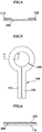
- FIGS. 2 to 6 are plan view and cross-sectional view illustrating various contact methods between an electrode and a thin film heating body.
- a distance (gap) between the first and second electrodes (110, 120) in a connection structure between the thin film heating body (200) and the electrode (100) in FIG. 2 may be relatively lengthily formed in order to prevent short-circuit between the first and second electrodes (110, 120).
- an end of the first electrode (110) may be formed with a first width reducer (115) formed to be narrower than a width of the first electrode (110), and the first width reducer (115) may be extended toward the second electrode (120).
- the first width reducer (115) may be formed in a curved shape when viewed from a plane.
- a length between the first and second width reducers (115, 125) in the connection structure between the thin film heating body (200) and the electrode (100) in FIGS. 5 and 6 may be formed to be relatively shorter than what is shown in FIGS. 3 and 4 .
- the cover film (320) illustrated in FIG. 1 may be formed with the transparent heating film and an opening exposing the first and second electrodes (110, 120) to electrically connect the first and second electrodes (110, 120) forming the electrode (100).
- the insulation member (600) may function to insulate the first heating structure (525) and the second heating body (550) from an outside conductor by wrapping the first heating structure (525) and the second heating body (550) and to prevent the first heating structure (525) and the second heating body (550) from being damaged by a force applied from an external force.
- An end of the second electrode pattern (514) at the first electrode (510) may be formed with a second width reducer (515) more narrowly formed in width than the second electrode pattern (514), and the second width reducer (515) may be extended toward the first electrode pattern (512).
- the second thin film heating body (540) may be electrically connected to the third and fourth width reducers (533,535).
- a distance between the first and second width reducers (513, 515) and the third and fourth width reducers (533, 535) in the connection structure of FIG. 9 may be relatively shortly formed over what is shown in FIG. 8 .
- a distance between the first and second electrode patterns (512, 514) and the third and fourth electrode patterns (532, 534) in the connection structure of FIG. 10 may be relatively shortly formed over what is shown in FIG. 9 .
- a transparent heating film (935) that is transparent and that generates a heat when a power is provided may be formed at a bottom surface of the lens (930) in the exemplary embodiment of the present invention.
- the camera thin film heater (800) may include a first heating structure (525) and a second heating structure (550), and a part of the power provided to the first heating structure (525) may be provided to the first heating structure (525), the transparent heating film (935) and the second heating structure (550), whereby the transparent heating film (935) can be heated.
Abstract
Description
- The teachings in accordance with exemplary and non-limiting embodiments of this invention relate generally to a camera module thin film heater and a camera module having the same.
- In general, portable communication equipment such as a smart phone and a tablet PC, a gamer are mounted with a camera module in order to photograph a photograph or an image.
- The camera module may include an image sensor that converts an incident outside light to an image, and at least one lens arranged on an optical axis of the image sensor.
- The lens is subject to an influence of outside air because of being arranged on an outside of the camera module to thereby allow the lens to be frequently generated with frost, freezing and dew condensation. When the lens is formed with frost, freezing and dew condensation, it should be apparent that the camera module suffers from greatly degraded performances.
- Although a hot wire generating a heat used to be arranged on a camera module in order to avoid generation on a lens of frost, freezing and dew condensation, a temperature sensor and a temperature control unit had to be additionally mounted on the camera module in order to prevent generation of frost, freezing and dew condensation on the lens.
- Furthermore, a lot of times are consumed to increase a lens temperature to a designated temperature in order to prevent frost, freezing and dew condensation on the lens,
- Particularly, when an outside temperature is very low, a lot of times are required to heat the lens temperature to a target temperature, and conversely, when a heat is generated from a hot wire if an outside temperature is high or a temperature of a camera module is high, there is also a high risk of the camera module being burnt out.
- Meantime, when a hot wire to control a temperature using a temperature sensor and a temperature control unit is used in order to prevent a lens from being formed with frost, freezing and dew condensation, it is very difficult design-wise to directly mount a lens on a temperature sensor. In addition, when a temperature sensor is arranged at a place separated from a lens because of difficulty in directly mounting a temperature sensor on the lens, it is difficult to accurately control a temperature on the lens due to difficulty in sensing a temperature accurately.
- The present invention is to provide a camera module thin film heater configured to prevent and avoid frost, dew condensation and freezing by allowing a lens module to reach a target temperature of a lens within a short period of time, and suppressing generation of fire due to overheating, even when operated in a high environment, and by not mounting a temperature sensor and a temperature control unit, thereby greatly reducing a manufacturing cost, and a camera module using the same.
- In one general aspect of the present invention, there is provided a camera module thin film heater, comprising:
- an electrode;
- a thin film heating body electrically connected to the electrode and having a variable resistance corresponding to a heating temperature; and
- an insulation member surrounding the electrode and the thin film heating body.
- Preferably, but not necessarily, the electrode may include a first electrode and a second electrode spaced apart from the first electrode, wherein the thin film heating body may be electrically connected to a distal end of the first electrode and the second electrode.
- Preferably, but not necessarily, the electrode may include a first electrode and a second electrode spaced apart from the first electrode, wherein the first electrode may include a first width reducer where a width decreases, and the second electrode may include a second width reducer where a width is decreased, and the thin film heating body may be electrically connected to the first and second width reducers.
- Preferably, but not necessarily, the electrode may include a first electrode and a second electrode spaced apart from the first electrode, wherein a portion of the first electrode and a portion of the second electrode may be mutually overlapped, and the thin film heating body may be interposed between the first electrode and the second electrode.
- Preferably, but not necessarily, the insulation member may include a base film arranged with the electrodes and the thin film heating body, and a cover film bonded to the base film.
- In another general aspect of the present invention, there is provided a camera module thin film heater, comprising:
- a first heating structure electrically connected to a first electrode and including a first thin film heating body in which a resistance changes in response to a heating temperature;
- a second thin film heating structure including a second thin film heating body insulated from the first heating structure and electrically connected to the first heating structure in which a resistance changes in response to a heating temperature; and
- an insulation member having an opening to insulate the first and second heating structures and exposing a portion of the first and second electrodes.
- Preferably, but not necessarily, the camera module thin film heater may further comprise third electrodes disposed at an outside of the insulation member to be electrically connected to the first and second electrodes through the opening.
- Preferably, but not necessarily, the third electrodes may be electrically connected to a transparent heater film that covers a camera lens.
- Preferably, but not necessarily, the first electrode may include first and second electrode patterns electrically connected to the first thin film heating body, wherein the second electrode may include third and fourth electrode patterns electrically connected to the second thin film heating body.
- Preferably, but not necessarily, the first electrode may include first and second electrode patterns electrically connected to the first thin film heating body, wherein the second electrode may include third and fourth electrode patterns electrically connected to the second thin film heating body, wherein the first and second electrode patterns may include first width reducers in which a width is reduced, the third and fourth electrode patterns may include second width reducers in which a width is reduced, and the first thin film heating bodies may be electrically connected to the first and second width reducers, and the second thin film heating bodies may be electrically connected to the third and fourth electrode patterns.
- Preferably, but not necessarily, the first electrode may include a first electrode pattern and a second electrode pattern overlapped with the first electrode pattern, the second electrode may include a third electrode pattern and a fourth electrode pattern overlapped with the third electrode pattern, and the first thin film heating body may be interposed between the first and second electrode patterns, and the second thin film heating body may be interposed between the third and fourth electrode patterns.
- Preferably, but not necessarily, the insulation member may include the first and second electrodes, a base film arranged with the first and second heating structures, and a cover film bonded to the base film and formed with openings.
- In still another general aspect of the present invention, there is provided a camera module, comprising:
- a camera module body including an image sensor, and a lens arranged on an optical axis of the image sensor; and
- a thin film heater including an electrode, at least one thin film heating body electrically connected to the electrode, variable in resistance in response to a heating temperature and arranged about the lens; and
- an insulation member encompassing the electrode and the thin film heating body.
- Preferably, but not necessarily, a portion of the electrode may be extended along a lateral surface of the camera module body to be electrically connected to an outside terminal.
- In still further general aspect of the present invention, there is provided a camera module, comprising:
- a camera module body including an image sensor, a lens arranged on an optical axis of the image sensor and a transparent heating film covering the lens; an insulation member including a first heating structure including a first thin film heating body contacted to the lens, electrically connected to a first electrode and changing in resistance in response to a heating temperature, a second heating structure including a second thin film heating body insulated from the first heating structure, electrically connected to a second electrode, and changing in resistance in response to a heating temperature, and an opening exposing a part of the first and second electrodes by insulating the first and second heating structures; and
- a third electrode electrically connecting the first electrode and the transparent heating film and electrically connecting the second electrode and the transparent heating film.
- Preferably, but not necessarily, the transparent heating film may include an ITO (Indium Tin Oxide).
- Preferably, but not necessarily, the transparent heating film may be disposed at a bottom surface of the lens facing the thin film heater.
- The camera module thin film heater and the camera module using the same according to the present invention is advantageous in that frost, dew condensation and freezing are prevented and avoided by allowing a lens module to reach a target temperature of a lens within a short period of time, to suppress generation of fire due to overheating, even when operated in a high environment, and by not mounting a temperature sensor and a temperature control unit, thereby greatly reducing a manufacturing cost.
-
-
FIG. 1 is an exploded perspective view illustrating a camera module thin film heater according to a first exemplary embodiment of the present invention. -
FIGS. 2 to 6 are plan view and cross-sectional view illustrating various contact methods between an electrodes and a thin film heating body. -
FIG. 7 is an exploded perspective view illustrating a camera module thin film heater according to another exemplary embodiment of the present invention. -
FIGS. 8 to 10 are plan views illustrating various contact methods of first heating structure and second heating structure. -
FIG. 11 is a cross-sectional view illustrating a camera module including a thin film heater according to still another exemplary embodiment of the present invention. -
FIG. 12 is a cross-sectional view illustrating a camera module including a thin film heater according to still another exemplary embodiment of the present invention. - It should be appreciated that only elements necessary for understanding the exemplary embodiments will be explained and detailed descriptions of well-known functions, configurations or constructions are omitted for brevity and clarity so as not to obscure the description of the present invention with unnecessary detail.
- Unless otherwise defined, all terms used herein have the same meaning as commonly understood by one of ordinary skill in the art to which this invention belongs. It will be further understood that terms, such as those defined in commonly used dictionaries, should be interpreted as having a meaning that is consistent with their meaning in the context of the relevant art and the present invention.
- It should be understood that configurations illustrated in the exemplary embodiments and drawings described in the present specification are merely preferable exemplary embodiments, and do not represent all technical ideas of the present invention, and therefore, numerous variations, modifications, and additional embodiments are possible, and accordingly, all such variations, modifications, and embodiments are to be regarded as being within the scope of this application.
-
FIG. 1 is an exploded perspective view illustrating a camera module thin film heater according to a first exemplary embodiment of the present invention. - Referring to
FIG. 1 , the camera module thin film heater (400) according to the first exemplary embodiment of the present invention may include an electrode (100), a thin film heating body (200) and an insulation member (300). - The electrode (100) may include a first electrode (110) and a second electrode (120), for example. The first electrode (110) may be formed to take a thin film shape when viewed from a plane, and the first electrode (110) may be manufactured with a material excellent in electric conductivity.
- For example, the conductive material to be used as material for the first electrode (110) may be copper, copper alloy, aluminum and aluminum alloy. In addition thereto, the first electrode (110) may be manufactured with a transparent electrode having an electric conductivity capable of generating a heat by self-resistant component of the first electrode (110) such as an ITO (Indium Thin Oxide), for example.
- As illustrated in
FIG. 1 , the first electrode (110) may be formed in a thin film shape. A portion of the first electrode (110) may be a straight part having a square shape and a curved part having a curved shape may be formed from a distal end of the straight part. The second electrode (120) may be in a state so arranged as to be spaced apart or insulated from the first electrode (110). The second electrode (120) may take a same shape as that of the first electrode (110), for example, and the second electrode (120) may be so arranged as to be symmetrical with the first electrode (110). - The second electrode (120) may be formed to take a thin film shape, when viewed from a plane, and the second electrode (120) may be manufactured with a material excellent in electric conductivity. For example, the second electrode (120) may be manufactured with the same material as that of the first electrode (110).
- Although the exemplary embodiment of the present invention has explained that the first and second electrodes (110,120) are made of same material, the first and second electrodes (110,120) may be made with materials having mutually different electric conductivity.
- The thin film heating body (200) may be manufactured with a thin film shape, where one end of the thin film heating body (200) may be electrically connected to the first electrode (110), and the other end of the thin film heating body (200) may be electrically connected to the second electrode (120). The thin film heating body (200) and the electrode (100) may be partially overlapped to be electrically connected.
- In the exemplary embodiment of the present invention, the thin film heating body (200) may take a partially opened ring shape when viewed from a plane surface, the thin film heating body (200), the first electrode (110) and the second electrode (120) may be mutually electrically connected to form a ring shape when viewed from a plane surface.
- The thin film heating body (200) may be electrically connected to the first and second electrodes (110, 120) to allow a power to be provided to the thin film heating body (200) through the first and second electrodes (110,120) whereby a heat can be generated from the thin film heating body (200).
- When the first electrode (110), the thin film heating body (200) and the second electrode (120) are mutually electrically connected, these three elements may be formed to take a circular-ring shape when viewed from a plane surface.
- The thin film heating body (200) may have an electric resistance-actively changing electric characteristic in response to a current temperature or a heating temperature of the thin film heating body (200).
- The thin film heating body (200) in the exemplary embodiment of the present invention may have an electric characteristic where an electric resistance quickly increases when a temperature increases differently from a resistance heating body like a nichrome wire, and the electric resistance conversely decreases when the temperature decreases.
- The thin film heating body (200) may include a PTC (Positive Temperature Coefficient) material, and may be manufactured in a shape of a semiconductor device. The thin film heating body (200) in the exemplary embodiment of the present invention may be formed with an opaque material.
- In an operation of the thin film heating body (200), when a power is supplied to the thin film heating body (200) through the electrode (100), a heat is started to be generated from the thin film heating body (200) through self- resistance, and an electric resistance of the thin film heating body (200) also increases as the heating temperature of thin film heating body (200) increases.
- When the temperature of the thin film heating body (200) increases to a particular temperature, resistance of the thin film heating body (200) also increases, such that the temperature of thin film heating body (200) does not rise to a designated temperature due to increased resistance of the thin film heating body (200), whereby fire can be avoided by the said characteristics of the thin film heating body (200).
- Meantime, when the temperature of the thin film heating body (200) decreases, resistance of the thin film heating body (200) also decreases to increase the temperature of thin film heating body (200), where this process is being repeated to allowing maintaining the temperature of the thin film heating body (200) within a predetermined scope.
- The thin film heating body (200), in which electric resistances actively change in response to temperatures as detailed above, can advantageously reach a target temperature within a short period of time without separate temperature sensors and temperature control units, and is not heated above a target temperature, and as a result, there is still another advantage of less risk of fire and a predetermined temperature being maintained at all times.
- The thin film heating body (200), which has various advantages as discussed above, can be applied to a lens of a camera module frequently generated with frost, freezing and dew condensation by outside air, and installed at a limited space where a temperature sensor is difficult to be directly mounted.
- The heating characteristics of the thin film heating body (200) in the exemplary embodiment of the present invention can be variably changed by changing contact conditions between the electrode (100) and the thin film heating body (200).
-
FIGS. 2 to 6 are plan view and cross-sectional view illustrating various contact methods between an electrode and a thin film heating body. - Referring to
FIG. 2 , a distal end of one side of the thin film heating body (200) may be electrically connected to an end of the first electrode (110) of the electrode (100), and a distal end of the other side facing the distal end of one side of the thin film heating body (200) may be electrically connected to an end of the second electrode (120) of the electrode (100). - A distance (gap) between the first and second electrodes (110, 120) in a connection structure between the thin film heating body (200) and the electrode (100) in
FIG. 2 may be relatively lengthily formed in order to prevent short-circuit between the first and second electrodes (110, 120). - Referring to
FIGS. 3 and4 , an end of the first electrode (110) may be formed with a first width reducer (115) formed to be narrower than a width of the first electrode (110), and the first width reducer (115) may be extended toward the second electrode (120). The first width reducer (115) may be formed in a curved shape when viewed from a plane. - An end of the second electrode (120) may be formed with a second width reducer (125) formed to be narrower than a width of the second electrode (120), and the second width reducer (125) may be extended toward the first electrode (110). The second width reducer (125) may be formed in a curved shape when viewed on a plane.
- The first width reducer (115) of the first electrode (110) and the second width reducer (125) of the second electrode (120) may be so arranged as to face each other when viewed on a plane, and a space may be formed between the first and second width reducers (115,125).
- The thin film heating body (200) may be electrically connected to the first and second width reducers (115,125), and the thin film heating body (200) may be curvedly formed.
- A length between the first and second width reducers (115, 125) in the connection structure between the thin film heating body (200) and the electrode (100) in
FIGS. 3 and4 may be formed to be relatively shorter than what is shown inFIG. 2 . - Referring to
FIGS. 5 and 6 , an end of the first electrode (110) may be extended toward the second electrode (120) without decreased area, and an end of the second electrode (120) may be extended toward the first electrode (110) without decreased area, and the first and second electrodes (110, 120) may be so arranged as to be mutually overlapped. The thin film heating body (200) may be interposed between the first and second electrodes (110,120). - A length between the first and second width reducers (115, 125) in the connection structure between the thin film heating body (200) and the electrode (100) in
FIGS. 5 and 6 may be formed to be relatively shorter than what is shown inFIGS. 3 and4 . - As illustrated in
FIGS. 2 to 6 , an amount of heat generated from the thin film heating body (200) can be changed by variably changing the connection structure between the thin film heating body (200) and the electrode (100). - Referring to
FIG. 1 again, the insulation member (300) may function to insulate the thin film heating body (200) and the electrode (100) from an outside conductor wrapping the electrode (100) and the thin film heating body (200) and to prevent the thin film heating body (200) and the electrode (100) from being damaged by a force applied from an external force. - The insulation member (300) may include a base film (310) and a cover film (320), for example. The electrode (100) and the thin film heating body (200) electrically connected to the electrode (100) may be interposed between the base film (310) and cover film (320). The mutual connection between the base film (310) and the cover film (320) may allow insulating the electrode (100) and the thin film heating body (200) between the base film (310) and the cover film (320).
- The camera module thin film heater (400) illustrated in
FIGS. 1 to 6 may be particularly adequate when a transparent heating film including the ITO (Indium Tin Oxide) material, which is a transparent electrode, is not formed at an upper surface of a bottom surface of the lens, which is a subject to be heated. - When a transparent heating film comprised of an ITO material which is a transparent electrode is formed on an upper surface or a bottom surface of the lens which is a subject to be heated, the cover film (320) illustrated in
FIG. 1 may be formed with the transparent heating film and an opening exposing the first and second electrodes (110, 120) to electrically connect the first and second electrodes (110, 120) forming the electrode (100). -
FIG. 7 is an exploded perspective view illustrating a camera module thin film heater (800) according to another exemplary embodiment of the present invention. - Referring to
FIG. 7 , the camera module thin film heater (800) may include a first heating structure (525), a heating structure (500) including a second heating structure (550) and an insulation member (600). The camera module thin film heater in the exemplary embodiment of the present invention may further include a third electrode (700) additionally arranged to the insulation member (600). - The first heating structure (525) may include a first electrode (510) and a first thin film heating body (520). The first electrode (510) and the first thin film heating body (520) may be electrically and mutually connected.
- The first electrode (510) may include a first electrode pattern (512) and a second electrode pattern (514), for example. The first electrode pattern (512) may be formed in a thin film shape when viewed from a plane, and the first electrode pattern (512) may be manufactured with a material excellent in electric conductivity.
- For example, the conductive material to be used as material for the first electrode pattern (512) may be copper, copper alloy, aluminum and aluminum alloy, for example. In addition thereto, the first electrode pattern (512) may be manufactured with an ITO (Indium Thin Oxide) material, a transparent electrode having an electric conductivity capable of generating a heat by self-resistant component of the first electrode pattern (512) such as an ITO (Indium Thin Oxide).
- As illustrated in
FIG. 7 , the first electrode pattern (512) may include a straight part of rectangular shape, and a curved part extended in a curved shape from an end of the straight part. The second electrode pattern (514) may take a same shape and be made of same material as that of the first electrode pattern (512), and the second electrode pattern (514) may be arranged in a symmetrical shape with the first electrode pattern (512). - Although the first and second electrode patterns (512, 514) are illustrated and explained to be formed with the same conductive material in the exemplary embodiment of the present invention, the first and second electrode patterns (512, 514) may be manufactured with mutually different conductive materials.
- The first thin film heating body (520) may be formed in a shape of a thin film or coated with a thin film, and the first thin film heating body (520) may take a curved shape when viewed on a plane.
- Unlike a resistance heating body like the nichrome wire, the first thin film heating body (520) may have an electric characteristic in which an electric resistance quickly increases when a temperature increases, and the electric resistance conversely decreases when the temperature decreases.
- For example, the first thin film heating body (520) may include a PTC (Positive Temperature Coefficient) material, and may be manufactured in a shape of a semiconductor device. The first thin film heating body (520) may be interposed between the first and second electrode patterns (512,514), where the first and second electrode patterns (512,514) and the first thin film heating body (200) may be electrically and mutually connected.
- The first heating structure (525) including the mutually electrically connected first electrode pattern (512), the first thin film heating body (520) and the second electrode pattern (514) may be formed in a semi-circular strip shape adequate for allowing the first heating body (525) to wrap a portion of round lens.
- Although the exemplary embodiment of the present invention has explained that the first heating structure (525) is formed with a semi-circular strip shape, the first heating structure (525) may be changed in shape in response to the lens shape.
- Referring to
FIG. 7 again, the second heating structure (550) may include a second electrode (530) and a second thin film heating body (540). The second heating structure (550) in the exemplary embodiment of the present invention may be spaced apart from the first heating structure (525), the second heating structure (550) and the first heating structure (525) may be symmetrically arranged. - The second electrode (530) of the second heating structure (550) and the second thin film heating body (540) may be electrically and mutually connected. The second electrode (530) may include a third electrode pattern (532) and a fourth electrode pattern (534). The third electrode pattern may take a shape of a thin film, when viewed on a plane, and the third electrode pattern (532) may be manufactured with a material excellent in electric conductivity.
- For example, an electrically conductive material to be used for the third electrode pattern (532) may include a copper, a copper alloy and an aluminum alloy. In addition thereto, the third electrode pattern (532) may be manufactured with an ITO (Indium Thin Oxide) which is a transparent electrode having an electric conductivity capable of generating a heat by self-resistant component.
- As illustrated in
FIG. 7 , a portion of the third electrode pattern (532) may be formed in a shape of a straight line and a portion of the third electrode pattern (532) may be curvedly shaped. The fourth electrode pattern (534) may be spaced apart from the third electrode pattern (532), and the fourth electrode pattern (534) may be manufactured with a same conductive material as that of the third electrode pattern (532). - Although the third and fourth electrode patterns (532, 534) are illustrated and explained to be formed with the same conductive material in the exemplary embodiment of the present invention, the third and fourth electrode patterns (532, 534) may be manufactured with mutually different conductive materials.
- The second thin film heating body (540) may be formed in a thin film shape, and the second thin film heating body (540) may be formed with a shape of a curved strip.
- Unlike a resistance heating body like the nichrome wire, the second thin film heating body (540) may have an electric characteristic in which an electric resistance quickly increases when a temperature increases, and the electric resistance conversely decreases when the temperature decreases.
- For example, the second thin film heating body (540) may include a PTC (Positive Temperature Coefficient) material, and may be manufactured in a shape of a semiconductor device. The second thin film heating body (540) may be interposed between the third and fourth electrode patterns (532,534), where the third and fourth electrode patterns (532,534) and the second thin film heating body (540) may be electrically and mutually connected.
- The second heating structure (550) including the mutually electrically connected third electrode pattern (532), the second thin film heating body (540) and the fourth electrode pattern (534) may be formed in a semi-circular strip shape adequate for allowing wrapping remaining portions of lens module that are not wrapped by the first heating structure (525).
- Although the exemplary embodiment of the present invention has explained that the second heating structure (550) is formed with a semi-circular strip shape, the second heating structure (550) may be changed in shape in response to the lens shape.
- Referring to
FIG. 7 again, the insulation member (600) may function to insulate the first heating structure (525) and the second heating body (550) from an outside conductor by wrapping the first heating structure (525) and the second heating body (550) and to prevent the first heating structure (525) and the second heating body (550) from being damaged by a force applied from an external force. - The insulation member (600) may include a base film (610) and a cover film (620), for example. The first heating structure (525) and the second heating body (550) may be interposed between the base film (610) and cover film (620). The mutual connection between the base film (610) and the cover film (620) may allow insulating the first heating structure (525) and the second heating body (550) between the base film (610) and the cover film (620).
- The cover film (620) of the insulation member (600) in the exemplary embodiment of the present invention may be formed with an opening (625) exposing the second electrode pattern (514) and the fourth electrode pattern (534) respectively. The opening (625) may be formed to connect an outside conductor or an outside heater that electrically and mutually connects the first heating structure (525) and the second heating structure (550).
- Although the opening (625) is illustrated and explained to be formed at the cover film (620) in the exemplary embodiment of the present invention, the opening (625) may be formed at the first electrode pattern (512) and the second electrode pattern (514).
- The third electrode (700) may be disposed on the cover film (620) of the insulation member (600), and the third electrode (700) may be electrically connected to the second electrode pattern (514) and the fourth electrode pattern (534) through the opening (625). The third electrode (700) may be electrically connected to a transparent heating film disposed at an upper surface or a bottom surface of the lens mounted on the camera module.
- In the exemplary embodiment of the present invention, the power provided to the first electrode (510) in response to the third electrode (700) and the transparent heating film being electrically connected may pass the first thin film heating body (520), the transparent heating film, the second electrode (530) and second thin film insulator (540) to allow the transparent heating film, the first and second thin film heating bodies (520,540) to generate a heat.
- The thin film heating body (520) included in the first heating structure (525) of the camera module thin film heater (800) illustrated in
FIG. 7 , and the second thin film heating body (540) included in the second heating structure (550) are such that resistance changes in active response to temperature, whereby a target temperature can be advantageously reached within a short period of time without separate temperature sensors and temperature control units, and heat is not reached above a target temperature, and as a result, there is another advantage of less risk of fire and a predetermined constant temperature scope being maintained at all times. - The camera module thin film heater (800), which has various advantages as discussed above, can be easily mounted to a lens of a camera module frequently generated with frost, freezing and dew condensation by outside air, and installed at a limited space where a temperature sensor is difficult to be mounted.
- The heating characteristics of the heat-generating first and second thin film heating bodies (520, 540) in the exemplary embodiment of the present invention can be variably realized by changing contact conditions between the first and second electrode patterns (512, 514) and the first thin film heating body (520) and contact conditions between the third and fourth electrode patterns (532, 534) and the second thin film heating body (540).
-
FIGS. 8 to 10 are plan views illustrating various contact methods of first heating structure and second heating structure. - Referring to
FIG. 8 , a distal end of one side at the first thin film heating body (520) may be contacted in series to the first electrode pattern (512) of first electrode (510) and to the second electrode pattern (514) of the first electrode (510). - A distance between the first and second electrode patterns (512, 514) in the connection structure between the first thin film heating body (520) and the first and second electrode patterns (512,514) may be relatively lengthily formed.
- Referring to
FIG. 9 , an end of the first electrode pattern (512) at the first electrode (510) may be formed with a first width reducer (513) more narrowly formed in width than the first electrode pattern (512), and the first width reducer (513) may be extended toward the second electrode pattern (514). - An end of the second electrode pattern (514) at the first electrode (510) may be formed with a second width reducer (515) more narrowly formed in width than the second electrode pattern (514), and the second width reducer (515) may be extended toward the first electrode pattern (512).
- The first thin film heating body (520) may be electrically connected to the first and second width reducers (513,515) respectively. An end of the third electrode pattern (532) at the second electrode (530) may be formed with a third width reducer (533) more narrowly formed in width than the third electrode pattern (532), and the third width reducer (532) may be extended toward the fourth electrode pattern (534).
- An end of the fourth electrode pattern (534) at the second electrode (530) may be formed with a fourth width reducer (535) more narrowly formed in width than the fourth electrode pattern (534), and the fourth width reducer (535) may be extended toward the third electrode pattern (532).
- The second thin film heating body (540) may be electrically connected to the third and fourth width reducers (533,535).
- A distance between the first and second width reducers (513, 515) and the third and fourth width reducers (533, 535) in the connection structure of
FIG. 9 may be relatively shortly formed over what is shown inFIG. 8 . - Referring to
FIG. 10 , the first electrode pattern (512) of the first electrode (510) and the second electrode pattern (514) may be mutually overlapped, and the third electrode pattern (532) of the second electrode (530) and the fourth electrode pattern (535) may be mutually overlapped. - The first thin film heating body (520) may be interposed between the mutually overlapped first electrode pattern (512) and the second electrode pattern (514), and a second thin film heating body (540) may be interposed between the mutually overlapped third electrode pattern (532) and the fourth electrode pattern (534).
- A distance between the first and second electrode patterns (512, 514) and the third and fourth electrode patterns (532, 534) in the connection structure of
FIG. 10 may be relatively shortly formed over what is shown inFIG. 9 . - An amount of heat generated from the first and second thin film heating bodies (520, 540) may be controlled by variably changing the connection structure as illustrated in
FIGS. 8 ,9 and10 . -
FIG. 11 is a cross-sectional view illustrating a camera module including a thin film heater according to still another exemplary embodiment of the present invention. - The camera thin film heater illustrated in
FIG. 11 has a substantially same structure as that of the camera module thin film heater (400) illustrated inFIGS. 1 to 6 . Thus, any recurrent and repeated explanation that is same in structure will be omitted, and same names and reference numerals will be provided to the same structures. - Referring to
FIG. 11 , a camera module (950) may include a camera module body (940) and a camera thin film heater (400). - The camera module body (940) may include a body (910) formed with an accommodation space, an image sensor (920) disposed at an inside of the body (910) and a lens (930).
- The camera thin film heater (400) in the exemplary embodiment of the present invention may be interposed between the lens (930) and then body (910).
- The camera thin film heater (400) may include a thin film heating body (200) generating a heat by a power provided through the electrode (100), where the thin film heating body (200) has an electric characteristic in which resistances are changed in response to the heating temperature.
- The camera thin film heater (400) may directly contact the lens (200) to provide a heat to the lens (200), whereby frost, dew condensation and freezing are prevented from being formed.
- A portion of the electrode (100) electrically connected to the thin film heating body (200) in the camera thin film heater (400) may be extended to a bottom surface of the body (910) along a lateral surface of the body (910), and the electrode (100) may be provided with a power from outside.
-
FIG. 12 is a cross-sectional view illustrating a camera module (1000) including a thin film heater according to still another exemplary embodiment of the present invention. - The camera thin film heater illustrated in
FIG. 12 has a substantially same structure as that of the camera module thin film heater (800) illustrated inFIGS. 7 to 10 . Thus, any recurrent and repeated explanation that is same in structure will be omitted, and same names and reference numerals will be provided to the same structures. - Referring to
FIG. 12 , the camera module (1000) may include a camera module body (940) and a camera thin film heater (800). - The camera module body (940) may include a body (910) formed with an accommodation space, an image sensor (920) disposed at an inside of the body (910) and a lens (930).
- A transparent heating film (935) that is transparent and that generates a heat when a power is provided may be formed at a bottom surface of the lens (930) in the exemplary embodiment of the present invention.
- Although
FIG. 12 has illustrated and explained that the transparent heating film (935) is formed at a bottom surface of the lens (930), the transparent heating film (930) may be formed at an upper surface of the lens (935), and when the transparent heating film (935) is formed at an upper surface of the lens (930), a portion of the transparent heating film (935) may be extended to a bottom surface of the lens (930). - The camera thin film heater (800) in the exemplary embodiment of the present invention may be interposed between the lens (930) and then body (910).
- The camera thin film heater (800) may include a first heating structure (525) and a second heating structure (550), and a part of the power provided to the first heating structure (525) may be provided to the first heating structure (525), the transparent heating film (935) and the second heating structure (550), whereby the transparent heating film (935) can be heated.
- The transparent heating film (935) in the exemplary embodiment of the present invention may include an ITO (Indium Tin Oxide) material adequate to generating a heat in accordance with the transparent heating film (935) being transparent and being provided with a power.
- The first thin film heating body (520) included in the first heating structure (525) and the second thin film heating body (550) included in the second heating structure (550) may be also heated in the course of the transparent heating film (935) being heated, and the first and second thin film heating bodies (520,540) may function as an auxiliary in heat-generation by the transparent heating film (935).
- The camera thin film heater (800) may multiply provide heat to the transparent heating film (935) directly formed on the lens (930) and to the first and second thin film heating bodies (520,540) to thereby prevent the lens (930) from being formed with frost, freezing and dew condensation.
- As detailed in the foregoing explanation, the present invention provides a camera module thin film heater and a camera module having the same that can prevent and avoid frost, condensation and freezing by reaching a target temperature of a lens within a short period of time, suppressing the generation of fire due to overheating even when operated in a high environment, and not including a temperature sensor and a temperature control unit, thereby greatly reducing the manufacturing cost.
- Although the abovementioned embodiments according to the present invention have been described in detail with reference to the above specific examples, the embodiments are, however, intended to be illustrative only, and thereby do not limit the scope of protection of the present invention. Thereby, it should be appreciated by the skilled in the art that changes, modifications and amendments to the above examples may be made without deviating from the scope of protection of the invention.
- The present invention discloses the following items:
- [Item 1] A camera module thin film heater, comprising:
- an electrode;
- a thin film heating body electrically connected to the electrode and having a variable resistance corresponding to a heating temperature; and
- an insulation member surrounding the electrode and the thin film heating body.
- [Item 2] The camera module thin film heater of item 1, wherein the electrode includes a first electrode and a second electrode spaced apart from the first electrode, wherein the thin film heating body is electrically connected to a distal end of the first electrode and the second electrode.
- [Item 3] The camera module thin film heater of item 1, wherein the electrode includes a first electrode and a second electrode spaced apart from the first electrode, wherein the first electrode includes a first width reducer where a width decreases, and the second electrode includes a second width reducer where a width is decreased, and the thin film heating body is electrically connected to the first and second width reducers.
- [Item 4] The camera module thin film heater of item 1, wherein the electrode includes a first electrode and a second electrode spaced apart from the first electrode, wherein a portion of the first electrode and a portion of the second electrode are mutually overlapped, and the thin film heating body is interposed between the first electrode and the second electrode.
- [Item 5] The camera module thin film heater of item 1, wherein the insulation member includes a base film arranged with the electrode and the thin film heating body, and a cover film bonded to the base film.
- [Item 6] A camera module thin film heater, comprising:
- a first heating structure including a first thin film heating body electrically connected to a first electrode and having a variable resistance corresponding to a heating temperature;
- a second heating structure insulated from the first heating structure, and including a second thin film heating body electrically connected to a second electrode and having a variable resistance corresponding to a heating temperature; and
- an insulation member having an opening to insulate the first and second heating structures and exposing a portion of the first and second electrodes.
- [Item 7] The camera module thin film heater of item 6, further comprising third electrodes disposed at an outside of the insulation member to be electrically connected to the first and second electrodes through the opening.
- [Item 8] The camera module thin film heater of item 6, wherein the third electrodes are electrically connected to a transparent heater film that covers a camera lens.
- [Item 9] The camera module thin film heater of item 6, wherein the first electrode includes first and second electrode patterns electrically connected to the first thin film heating body, wherein the second electrode includes third and fourth electrode patterns electrically connected to the second thin film heating body.
- [Item 10] The camera module thin film heater of item 6, wherein the first electrode includes first and second electrode patterns electrically connected to the first thin film heating body, wherein the second electrode includes third and fourth electrode patterns electrically connected to the second thin film heating body, wherein the first and second electrode patterns include first width reducers in which a width is reduced, the third and fourth electrode patterns include second width reducers in which a width is reduced, and the first thin film heating bodies are electrically connected to the first and second width reducers, and the second thin film heating bodies are electrically connected to the third and fourth electrode patterns.
- [Item 11] The camera module thin film heater of item 6, wherein the first electrode includes a first electrode pattern and a second electrode pattern overlapped with the first electrode pattern, the second electrode includes a third electrode pattern and a fourth electrode pattern overlapped with the third electrode pattern, and the first thin film heating body is interposed between the first and second electrode patterns, and the second thin film heating body is interposed between the third and fourth electrode patterns.
- [Item 12] The camera module thin film heater of item 6, wherein the insulation member includes the first and second electrodes, a base film arranged with the first and second heating structures, and a cover film bonded to the base film and formed with openings.
- [Item 13] A camera module, comprising:
- a camera module body including an image sensor, and a lens arranged on an optical axis of the image sensor; and
- a thin film heater including an electrode, at least one thin film heating body electrically connected to the electrode, variable in resistance in response to a heating temperature and arranged about the lens; and
- an insulation member encompassing the electrode and the thin film heating body.
- [Item 14] The camera module of item 13, wherein a portion of the electrode is extended along a lateral surface of the camera module body to be electrically connected to an outside terminal.
- [Item 15] A camera module, comprising:
- a camera module body including an image sensor, a lens arranged on an optical axis of the image sensor and a transparent heating film covering the lens;
- an insulation member including a first heating structure including a first thin film heating body contacted to the lens, electrically connected to a first electrode and changing in resistance in response to a heating temperature, a second heating structure including a second thin film heating body insulated from the first heating structure, electrically connected to a second electrode, and changing in resistance in response to a heating temperature, and an opening exposing a part of the first and second electrodes by insulating the first and second heating structures; and
- third electrodes electrically connecting the first electrode and the transparent heating film and electrically connecting the second electrode and the transparent heating film.
- [Item 16] The camera module of item 15, wherein the transparent heating film includes an ITO (Indium Tin Oxide).
- [Item 17] A camera module of item 15, wherein the transparent heating film is disposed at a bottom surface of the lens facing the thin film heater.
- The present invention can be used as a vehicular camera module, an exterior CCTV and a monitoring camera installed on an outside of a vehicle where a temperature difference is great.
Claims (15)
- A camera module thin film heater, comprising:an electrode(100);a thin film heating body(200) electrically connected to the electrode(100) and having a variable resistance corresponding to a heating temperature; andan insulation member(300) surrounding the electrode(100) and the thin film heating body(200),characterized in that the electrode(100) includes a first electrode(110) and a second electrode(120) spaced apart from the first electrode(110), wherein the thin film heating body(200) is electrically connected to a distal end of the first electrode(110) and the second electrode(120).
- The camera module thin film heater of claim 1, wherein the first electrode(110) includes a first width reducer(115) where a width decreases, and the second electrode(120) includes a second width reducer(125) where a width is decreased, and the thin film heating body(200) is electrically connected to the first and second width reducers(115, 125).
- The camera module thin film heater of claim 1, wherein the electrode(100) includes a first electrode(110) and a second electrode(120) spaced apart from the first electrode(110), wherein a portion of the first electrode(110) and a portion of the second electrode(120) are mutually overlapped, and the thin film heating body(200) is interposed between the first electrode(110) and the second electrode(120).
- The camera module thin film heater of claim 1, wherein the insulation member(300) includes a base film(310) arranged with the electrode(100) and the thin film heating body(200), and a cover film(320) bonded to the base film(310).
- The camera module thin film heater of claim 1, wherein the electrode(100) includes a first electrode(110) and a second electrode(120) spaced apart from the first electrode(110),
wherein the first electrode(110) and the second electrode(120) include a rectilinear portion and a curved surface portion extended from an end of the rectilinear portion. - The camera module thin film heater of claim 6, wherein the first electrode(110) and the second electrode(120) are symmetrical to each other.
- The camera module thin film heater of claim 1, wherein the thin film heating body(200) is formed in an annular shape partially opened.
- A camera module thin film heater of claim 1,
wherein the electrode(100) includes a first electrode(510) and a second electrode(53 0),
wherein the thin film heating body(500) includes a first thin film heating body(520) and a second thin film heating body(540),
further comprising a first heating structure(525) including the first thin film heating body(520) electrically connected to the first electrode(510) and having a variable resistance corresponding to a heating temperature, a second heating structure(550) insulated from the first heating structure(525), and including the second thin film heating body(540) electrically connected to the second electrode(530) and having a variable resistance corresponding to a heating temperature and an insulation member(600) having an opening(625) to insulate the first and second heating structures(525, 550) and exposing a portion of the first and second electrodes(510, 530). - The camera module thin film heater of claim 8, further comprising third electrodes(700) disposed at an outside of the insulation member(600) to be electrically connected to the first and second electrodes(510, 530) through the opening(625).
- The camera module thin film heater of claim 9, wherein the third electrodes(700) are electrically connected to a transparent heater film(935) that covers a camera lens(930).
- The camera module thin film heater of claim 10, wherein the transparent heater film(935) includes ITO(Indium Tin Oxide).
- The camera module thin film heater of claim 8, wherein the first electrode(510) includes first and second electrode patterns(512, 514) electrically connected to the first thin film heating body(520), wherein the second electrode(530) includes third and fourth electrode patterns(532, 534) electrically connected to the second thin film heating body(540).
- The camera module thin film heater of claim 8, wherein the first electrode(510) includes first and second electrode patterns(512, 514) electrically connected to the first thin film heating body(520), wherein the second electrode(530) includes third and fourth electrode patterns(532, 534) electrically connected to the second thin film heating body(540), wherein the first and second electrode patterns(512, 514) include first width reducers(513) in which a width is reduced, the third and fourth electrode patterns(532, 534) include second width reducers(515) in which a width is reduced, and the first thin film heating body(520) is electrically connected to the first and second width reducers(513, 515), and the second thin film heating body(540) is electrically connected to the third and fourth electrode patterns(532, 534).
- The camera module thin film heater of claim 8, wherein the first electrode(510) includes a first electrode pattern(512) and a second electrode pattern(514) overlapped with the first electrode pattern(512), the second electrode(514) includes a third electrode pattern(532) and a fourth electrode pattern(534) overlapped with the third electrode pattern(532), and the first thin film heating body(520) is interposed between the first and second electrode patterns(512, 514), and the second thin film heating body(540) is interposed between the third and fourth electrode patterns(532, 534).
- The camera module thin film heater of claim 8, wherein the insulation member(600) includes the first and second electrodes(510, 530), a base film(610) arranged with the first and second heating structures(525, 550), and a cover film(620) bonded to the base film(610) and formed with opening(625).
Applications Claiming Priority (3)
| Application Number | Priority Date | Filing Date | Title |
|---|---|---|---|
| KR1020150130091A KR102487620B1 (en) | 2015-09-15 | 2015-09-15 | Thin film type heater for camera module and camera module having the same |
| PCT/KR2016/010261 WO2017048014A1 (en) | 2015-09-15 | 2016-09-12 | Camera module thin film heater and camera module having same |
| EP16846835.3A EP3352008B1 (en) | 2015-09-15 | 2016-09-12 | Camera module thin film heater and camera module having same |
Related Parent Applications (2)
| Application Number | Title | Priority Date | Filing Date |
|---|---|---|---|
| EP16846835.3A Division EP3352008B1 (en) | 2015-09-15 | 2016-09-12 | Camera module thin film heater and camera module having same |
| EP16846835.3A Division-Into EP3352008B1 (en) | 2015-09-15 | 2016-09-12 | Camera module thin film heater and camera module having same |
Publications (2)
| Publication Number | Publication Date |
|---|---|
| EP3913432A2 true EP3913432A2 (en) | 2021-11-24 |
| EP3913432A3 EP3913432A3 (en) | 2022-03-23 |
Family
ID=58289532
Family Applications (2)
| Application Number | Title | Priority Date | Filing Date |
|---|---|---|---|
| EP21175344.7A Pending EP3913432A3 (en) | 2015-09-15 | 2016-09-12 | Camera module thin film heater and camera module having same |
| EP16846835.3A Active EP3352008B1 (en) | 2015-09-15 | 2016-09-12 | Camera module thin film heater and camera module having same |
Family Applications After (1)
| Application Number | Title | Priority Date | Filing Date |
|---|---|---|---|
| EP16846835.3A Active EP3352008B1 (en) | 2015-09-15 | 2016-09-12 | Camera module thin film heater and camera module having same |
Country Status (5)
| Country | Link |
|---|---|
| US (1) | US11143864B2 (en) |
| EP (2) | EP3913432A3 (en) |
| KR (2) | KR102487620B1 (en) |
| CN (1) | CN108027548B (en) |
| WO (1) | WO2017048014A1 (en) |
Families Citing this family (26)
| Publication number | Priority date | Publication date | Assignee | Title |
|---|---|---|---|---|
| KR102524129B1 (en) | 2016-02-15 | 2023-04-21 | 엘지이노텍 주식회사 | Heating device for camera module and camera module having the same |
| JP6723194B2 (en) * | 2017-04-26 | 2020-07-15 | 株式会社東海理化電機製作所 | Imaging device |
| CN107181902A (en) * | 2017-07-11 | 2017-09-19 | 信利光电股份有限公司 | One kind shooting epicranial plate and camera |
| JP2019046786A (en) * | 2017-09-04 | 2019-03-22 | 株式会社デンソー | Heater device |
| KR102123677B1 (en) * | 2018-08-21 | 2020-06-17 | 엘지전자 주식회사 | Electric Heater |
| JP7293969B2 (en) * | 2018-10-25 | 2023-06-20 | 株式会社デンソー | heater device |
| US11453366B2 (en) * | 2018-11-06 | 2022-09-27 | Motherson Innovations Company Limited | Heatable device for use with a vehicle-mounted image acquisition unit |
| KR102243382B1 (en) * | 2018-11-30 | 2021-04-22 | 에이치엔티 일렉트로닉스(주) | Camera module having a function of heating and manufacturing method of the same |
| KR20200077858A (en) * | 2018-12-21 | 2020-07-01 | 엘지이노텍 주식회사 | Camera module including liquid lens, and method for controlling the module |
| WO2020197289A1 (en) * | 2019-03-26 | 2020-10-01 | 엘지이노텍 주식회사 | Heating device and camera module |
| EP3978999A4 (en) * | 2019-05-31 | 2023-07-05 | LG Innotek Co., Ltd. | Camera module |
| JP7339023B2 (en) | 2019-06-07 | 2023-09-05 | マクセル株式会社 | Lens unit and camera module |
| US20220357572A1 (en) * | 2019-06-17 | 2022-11-10 | Ningbo Sunny Automotive Optech Co., Ltd. | Optical device and use thereof |
| JP2021012352A (en) * | 2019-07-09 | 2021-02-04 | パナソニックi−PROセンシングソリューションズ株式会社 | Surveillance camera and cover |
| KR102296895B1 (en) * | 2019-09-18 | 2021-09-01 | 주식회사 아이엠첨단소재 | Heating device and camera for vehicles using the same |
| US20210160969A1 (en) * | 2019-11-22 | 2021-05-27 | Honeywell International Inc. | Window heating apparatus |
| CN111983766A (en) * | 2019-12-31 | 2020-11-24 | 江西联创电子有限公司 | Optical lens and imaging module |
| US11927747B2 (en) | 2019-12-31 | 2024-03-12 | Jiangxi Lianchuang Electronic Co., Ltd. | Camera module, vehicle camera and monitoring system |
| DE102020200695A1 (en) * | 2020-01-22 | 2021-07-22 | Robert Bosch Gesellschaft mit beschränkter Haftung | Camera module |
| US11650391B2 (en) * | 2020-02-25 | 2023-05-16 | Littelfuse, Inc. | PPTC heater and material having stable power and self-limiting behavior |
| US20210400179A1 (en) * | 2020-06-18 | 2021-12-23 | Ford Global Technologies, Llc | Sensor system with cleaning and heating |
| SE2050801A1 (en) * | 2020-06-30 | 2021-12-31 | Orlaco Products B V | Camera system with lens heater |
| KR102483614B1 (en) * | 2020-09-01 | 2023-01-02 | 삼성전기주식회사 | Camera Module |
| CN117642672A (en) * | 2021-07-02 | 2024-03-01 | 泰立戴恩菲力尔商业系统公司 | Heating camera and related method |
| EP4123357A1 (en) * | 2021-07-23 | 2023-01-25 | Ficosa Adas, S.L.U. | Lens assembly, camera module having a lens assembly for motor vehicles, and a method for making a lens assembly |
| JP2023023904A (en) * | 2021-08-06 | 2023-02-16 | マクセル株式会社 | Heater, lens unit, camera module, on-vehicle system, mobile body, and method for incorporating heater |
Family Cites Families (24)
| Publication number | Priority date | Publication date | Assignee | Title |
|---|---|---|---|---|
| US4309596A (en) * | 1980-06-24 | 1982-01-05 | Sunbeam Corporation | Flexible self-limiting heating cable |
| DE3144275C1 (en) * | 1981-11-07 | 1983-04-14 | Grundig E.M.V. Elektro-Mechanische Versuchsanstalt Max Grundig & Co KG, 8510 Fürth | "Compact television camera for indoor or outdoor use" |
| JPH0738788A (en) | 1993-07-22 | 1995-02-07 | Sharp Corp | Camera monitor device |
| DE4436087C2 (en) * | 1994-10-10 | 2003-06-18 | Siedle & Soehne S | Heating device for a translucent protective pane of a protective housing of a camera |
| DE29514364U1 (en) * | 1995-09-07 | 1996-01-18 | Hohe Gmbh & Co Kg | Image acquisition module |
| JPH11231696A (en) * | 1998-02-10 | 1999-08-27 | Canon Inc | Heating body, heating device and image forming device |
| JP2001066934A (en) * | 1999-08-27 | 2001-03-16 | Canon Inc | Heating device and image forming device |
| US7480149B2 (en) * | 2004-08-18 | 2009-01-20 | Donnelly Corporation | Accessory module for vehicle |
| DE60333497D1 (en) | 2003-05-22 | 2010-09-02 | Fico Mirrors Sa | PHOTO MOUNTING MODULE WITH A HEATING DEVICE MONITORING THE ENVIRONMENT OF A MOTOR VEHICLE |
| DE10340900A1 (en) * | 2003-09-02 | 2005-03-24 | Valeo Schalter Und Sensoren Gmbh | Camera module with heated cover disc for monitoring car rear environment and stationary monitoring of buildings, house entrances, public places etc., containing lens, evaluator, |
| KR200342920Y1 (en) * | 2003-12-02 | 2004-02-19 | (주)동화이엔지 | camera with conductive heating film |
| JP4789572B2 (en) * | 2005-10-11 | 2011-10-12 | シチズン電子株式会社 | Liquid crystal lens device |
| KR20070018642A (en) * | 2005-08-10 | 2007-02-14 | 엘지전자 주식회사 | A method and a structure and a device of remove dampness on window for camera object lens |
| KR200424379Y1 (en) * | 2006-06-07 | 2006-08-22 | 김종만 | Window having transparent heater film |
| US20100084161A1 (en) * | 2008-10-08 | 2010-04-08 | Robert A. Neal | Conductive film and process for making same |
| DE102008063849A1 (en) * | 2008-12-19 | 2010-06-24 | Tesa Se | Heated surface element and method for its attachment |
| KR20100094838A (en) * | 2009-02-19 | 2010-08-27 | (주)씨프로 | A camera for preventing a humidity |
| JP5344346B2 (en) * | 2009-12-02 | 2013-11-20 | 山本光学株式会社 | Anti-fogging lenses and eye protection |
| KR20110068442A (en) * | 2009-12-16 | 2011-06-22 | 주식회사 오카스 | Heater for protecting frost of camera window and drive system thereof |
| EP2640161B1 (en) * | 2010-11-08 | 2017-11-08 | Panasonic Intellectual Property Management Co., Ltd. | Planar heating element and production method for same |
| TWM408051U (en) * | 2011-01-04 | 2011-07-21 | Topview Optronics Corp | Defogging and defrosting device for camera protection lens |
| WO2014001414A1 (en) * | 2012-06-26 | 2014-01-03 | Iee International Electronics & Engineering S.A. | Ptc heating device without electronic power control |
| JP6071366B2 (en) * | 2012-09-19 | 2017-02-01 | キヤノン株式会社 | Heater and image heating apparatus equipped with the heater |
| KR101462983B1 (en) * | 2013-09-27 | 2014-11-18 | 한국생산기술연구원 | Closed Circuit Television Camera employing transparent heating sheet |
-
2015
- 2015-09-15 KR KR1020150130091A patent/KR102487620B1/en active IP Right Grant
-
2016
- 2016-09-12 US US15/760,528 patent/US11143864B2/en active Active
- 2016-09-12 EP EP21175344.7A patent/EP3913432A3/en active Pending
- 2016-09-12 EP EP16846835.3A patent/EP3352008B1/en active Active
- 2016-09-12 CN CN201680053695.7A patent/CN108027548B/en active Active
- 2016-09-12 WO PCT/KR2016/010261 patent/WO2017048014A1/en active Application Filing
-
2023
- 2023-01-06 KR KR1020230002433A patent/KR20230010268A/en active IP Right Grant
Also Published As
| Publication number | Publication date |
|---|---|
| CN108027548A (en) | 2018-05-11 |
| EP3352008A1 (en) | 2018-07-25 |
| WO2017048014A1 (en) | 2017-03-23 |
| US20190041630A1 (en) | 2019-02-07 |
| EP3352008A4 (en) | 2018-09-05 |
| KR20230010268A (en) | 2023-01-18 |
| CN108027548B (en) | 2021-11-26 |
| KR20170032585A (en) | 2017-03-23 |
| KR102487620B1 (en) | 2023-01-12 |
| EP3913432A3 (en) | 2022-03-23 |
| US11143864B2 (en) | 2021-10-12 |
| EP3352008B1 (en) | 2021-06-30 |
Similar Documents
| Publication | Publication Date | Title |
|---|---|---|
| US11143864B2 (en) | Camera module thin film heater | |
| CN107534255B (en) | Connector component with temperature monitoring device | |
| CN106573542B (en) | Plug-in connector with temperature sensing device | |
| KR102240138B1 (en) | Heating element with temperature controlled and smoking set | |
| US7666033B1 (en) | Power plug with over temperature and over current protection | |
| JP2018059902A (en) | Temperature measurement assembly, electrical device assembly, battery pack connecting assembly, and battery pack | |
| TWI528407B (en) | Complex protection device for blocking abnormal state of current and voltage | |
| TWI545606B (en) | Complex protection device | |
| US20150364286A1 (en) | Complex protection device | |
| JP5443587B2 (en) | Sensor device and production method | |
| US20150249333A1 (en) | Complex protection device of blocking the abnormal state of current and voltage | |
| JP2019533885A (en) | Power contactor and method for manufacturing power contactor housing | |
| KR102411956B1 (en) | Gas sensor manufacturing method and corresponding gas sensor | |
| KR102174814B1 (en) | Assembly for connecting a flat plate to a voltage source with a built-in control unit | |
| KR20180006045A (en) | Lens assembly and camera module including the same | |
| TWI528406B (en) | Complex protection device for blocking abnormal state of current and voltage | |
| TWI547967B (en) | Complex protection device | |
| JP3219722U (en) | heater | |
| CN113906527B (en) | Device and use of a device | |
| JP2024046973A (en) | Heater units and their applications | |
| KR101155421B1 (en) | Temperature controller | |
| TW201546854A (en) | Complex protection device of blocking abnormal state of current and voltage | |
| TH124061B (en) | Pyroelectric infrared detectors and infrared wensers that use them | |
| TH66081B (en) | Pyroelectric infrared sensing element and infrared sensor used for that part | |
| TH124061A (en) | Pyroelectric infrared sensing element and infrared sensor used for that part |
Legal Events
| Date | Code | Title | Description |
|---|---|---|---|
| PUAI | Public reference made under article 153(3) epc to a published international application that has entered the european phase |
Free format text: ORIGINAL CODE: 0009012 |
|
| STAA | Information on the status of an ep patent application or granted ep patent |
Free format text: STATUS: THE APPLICATION HAS BEEN PUBLISHED |
|
| AC | Divisional application: reference to earlier application |
Ref document number: 3352008 Country of ref document: EP Kind code of ref document: P |
|
| AK | Designated contracting states |
Kind code of ref document: A2 Designated state(s): AL AT BE BG CH CY CZ DE DK EE ES FI FR GB GR HR HU IE IS IT LI LT LU LV MC MK MT NL NO PL PT RO RS SE SI SK SM TR |
|
| PUAL | Search report despatched |
Free format text: ORIGINAL CODE: 0009013 |
|
| AK | Designated contracting states |
Kind code of ref document: A3 Designated state(s): AL AT BE BG CH CY CZ DE DK EE ES FI FR GB GR HR HU IE IS IT LI LT LU LV MC MK MT NL NO PL PT RO RS SE SI SK SM TR |
|
| RIC1 | Information provided on ipc code assigned before grant |
Ipc: H05B 3/12 20060101ALN20220215BHEP Ipc: G02B 27/00 20060101ALI20220215BHEP Ipc: G03B 17/55 20210101AFI20220215BHEP |
|
| STAA | Information on the status of an ep patent application or granted ep patent |
Free format text: STATUS: REQUEST FOR EXAMINATION WAS MADE |
|
| 17P | Request for examination filed |
Effective date: 20220913 |
|
| RBV | Designated contracting states (corrected) |
Designated state(s): AL AT BE BG CH CY CZ DE DK EE ES FI FR GB GR HR HU IE IS IT LI LT LU LV MC MK MT NL NO PL PT RO RS SE SI SK SM TR |