KR20170032585A - Thin film type heater for camera module and camera module having the same - Google Patents
Thin film type heater for camera module and camera module having the same Download PDFInfo
- Publication number
- KR20170032585A KR20170032585A KR1020150130091A KR20150130091A KR20170032585A KR 20170032585 A KR20170032585 A KR 20170032585A KR 1020150130091 A KR1020150130091 A KR 1020150130091A KR 20150130091 A KR20150130091 A KR 20150130091A KR 20170032585 A KR20170032585 A KR 20170032585A
- Authority
- KR
- South Korea
- Prior art keywords
- electrode
- thin film
- heating element
- heating
- electrically connected
- Prior art date
Links
Images


Classifications
-
- G—PHYSICS
- G02—OPTICS
- G02B—OPTICAL ELEMENTS, SYSTEMS OR APPARATUS
- G02B7/00—Mountings, adjusting means, or light-tight connections, for optical elements
- G02B7/02—Mountings, adjusting means, or light-tight connections, for optical elements for lenses
- G02B7/028—Mountings, adjusting means, or light-tight connections, for optical elements for lenses with means for compensating for changes in temperature or for controlling the temperature; thermal stabilisation
-
- G—PHYSICS
- G03—PHOTOGRAPHY; CINEMATOGRAPHY; ANALOGOUS TECHNIQUES USING WAVES OTHER THAN OPTICAL WAVES; ELECTROGRAPHY; HOLOGRAPHY
- G03B—APPARATUS OR ARRANGEMENTS FOR TAKING PHOTOGRAPHS OR FOR PROJECTING OR VIEWING THEM; APPARATUS OR ARRANGEMENTS EMPLOYING ANALOGOUS TECHNIQUES USING WAVES OTHER THAN OPTICAL WAVES; ACCESSORIES THEREFOR
- G03B17/00—Details of cameras or camera bodies; Accessories therefor
- G03B17/55—Details of cameras or camera bodies; Accessories therefor with provision for heating or cooling, e.g. in aircraft
-
- G—PHYSICS
- G02—OPTICS
- G02B—OPTICAL ELEMENTS, SYSTEMS OR APPARATUS
- G02B27/00—Optical systems or apparatus not provided for by any of the groups G02B1/00 - G02B26/00, G02B30/00
-
- G—PHYSICS
- G02—OPTICS
- G02B—OPTICAL ELEMENTS, SYSTEMS OR APPARATUS
- G02B27/00—Optical systems or apparatus not provided for by any of the groups G02B1/00 - G02B26/00, G02B30/00
- G02B27/0006—Optical systems or apparatus not provided for by any of the groups G02B1/00 - G02B26/00, G02B30/00 with means to keep optical surfaces clean, e.g. by preventing or removing dirt, stains, contamination, condensation
-
- G—PHYSICS
- G03—PHOTOGRAPHY; CINEMATOGRAPHY; ANALOGOUS TECHNIQUES USING WAVES OTHER THAN OPTICAL WAVES; ELECTROGRAPHY; HOLOGRAPHY
- G03B—APPARATUS OR ARRANGEMENTS FOR TAKING PHOTOGRAPHS OR FOR PROJECTING OR VIEWING THEM; APPARATUS OR ARRANGEMENTS EMPLOYING ANALOGOUS TECHNIQUES USING WAVES OTHER THAN OPTICAL WAVES; ACCESSORIES THEREFOR
- G03B17/00—Details of cameras or camera bodies; Accessories therefor
- G03B17/02—Bodies
- G03B17/12—Bodies with means for supporting objectives, supplementary lenses, filters, masks, or turrets
-
- H—ELECTRICITY
- H04—ELECTRIC COMMUNICATION TECHNIQUE
- H04N—PICTORIAL COMMUNICATION, e.g. TELEVISION
- H04N23/00—Cameras or camera modules comprising electronic image sensors; Control thereof
- H04N23/50—Constructional details
- H04N23/54—Mounting of pick-up tubes, electronic image sensors, deviation or focusing coils
-
- H—ELECTRICITY
- H04—ELECTRIC COMMUNICATION TECHNIQUE
- H04N—PICTORIAL COMMUNICATION, e.g. TELEVISION
- H04N23/00—Cameras or camera modules comprising electronic image sensors; Control thereof
- H04N23/50—Constructional details
- H04N23/55—Optical parts specially adapted for electronic image sensors; Mounting thereof
-
- H—ELECTRICITY
- H05—ELECTRIC TECHNIQUES NOT OTHERWISE PROVIDED FOR
- H05B—ELECTRIC HEATING; ELECTRIC LIGHT SOURCES NOT OTHERWISE PROVIDED FOR; CIRCUIT ARRANGEMENTS FOR ELECTRIC LIGHT SOURCES, IN GENERAL
- H05B3/00—Ohmic-resistance heating
- H05B3/0004—Devices wherein the heating current flows through the material to be heated
-
- H—ELECTRICITY
- H05—ELECTRIC TECHNIQUES NOT OTHERWISE PROVIDED FOR
- H05B—ELECTRIC HEATING; ELECTRIC LIGHT SOURCES NOT OTHERWISE PROVIDED FOR; CIRCUIT ARRANGEMENTS FOR ELECTRIC LIGHT SOURCES, IN GENERAL
- H05B3/00—Ohmic-resistance heating
- H05B3/20—Heating elements having extended surface area substantially in a two-dimensional plane, e.g. plate-heater
- H05B3/22—Heating elements having extended surface area substantially in a two-dimensional plane, e.g. plate-heater non-flexible
- H05B3/26—Heating elements having extended surface area substantially in a two-dimensional plane, e.g. plate-heater non-flexible heating conductor mounted on insulating base
-
- H—ELECTRICITY
- H05—ELECTRIC TECHNIQUES NOT OTHERWISE PROVIDED FOR
- H05B—ELECTRIC HEATING; ELECTRIC LIGHT SOURCES NOT OTHERWISE PROVIDED FOR; CIRCUIT ARRANGEMENTS FOR ELECTRIC LIGHT SOURCES, IN GENERAL
- H05B3/00—Ohmic-resistance heating
- H05B3/20—Heating elements having extended surface area substantially in a two-dimensional plane, e.g. plate-heater
- H05B3/22—Heating elements having extended surface area substantially in a two-dimensional plane, e.g. plate-heater non-flexible
- H05B3/28—Heating elements having extended surface area substantially in a two-dimensional plane, e.g. plate-heater non-flexible heating conductor embedded in insulating material
Abstract
Description
본 발명은 카메라 모듈용 박막 히터 및 이를 갖는 카메라 모듈에 관한 것이다.
The present invention relates to a thin film heater for a camera module and a camera module having the same.
일반적으로 스마트 폰과 같은 휴대용 통신 장비, 태블릿 PC, 게임기 등에는 사진 또는 동영상을 촬영하기 위한 카메라 모듈이 장착되고 있다.In general, portable communication devices such as a smart phone, a tablet PC, and a game machine are equipped with a camera module for taking pictures or moving images.
카메라 모듈은 입사된 외부광을 이미지로 변환하는 이미지 센서 및 이미지센서의 광축 상에 배치된 적어도 렌즈를 포함하며, 렌즈는 집광 기능, 포커스 조절 등 다양한 기능을 수행한다.The camera module includes an image sensor that converts incident external light into an image, and at least a lens disposed on an optical axis of the image sensor. The lens performs various functions such as a light converging function, a focus adjusting function, and the like.
렌즈는 카메라 모듈의 외측에 배치되어 외기의 영향을 많이 받기 때문에 동절기에 렌즈에는 성에, 결로 및 빙결 등이 빈번하게 발생되고, 렌즈에 성에, 결로 및 빙결 등이 발생될 경우 카메라 모듈의 성능이 크게 저하된다.Since the lens is disposed outside the camera module and is heavily influenced by the outside air, the lens frequently experiences glare, condensation, freezing and the like in the winter season, and when the lens causes glare, condensation, icing, etc., .
렌즈에 성에, 결로 및 빙결이 발생되는 것을 방지하기 위해서, 종래에는 카메라 모듈에 열선을 감거나 열선을 배치하였으나, 열선 등을 이용하여 렌즈의 성에, 결로 및 빙결을 방지하기 위해서는 추가적으로 온도 센서 및 온도 제어 유닛 등을 필요로 한다.Conventionally, in order to prevent the lens from generating glare, condensation, and freezing, a hot wire is wound around the camera module or a hot wire is disposed. However, in order to prevent glare, condensation, A control unit, and the like.
단순히 열선을 이용하여 렌즈의 성에, 결로 및 빙결을 방지하기 위해서는 렌즈의 온도를 지정된 목표 온도까지 상승시키는데 많은 시간이 소요된다.In order to prevent the lens from glazing, condensation, and freezing by simply using a hot wire, it takes a long time to raise the temperature of the lens to a designated target temperature.
특히 외부 기온이 매우 낮을 경우 렌즈의 온도를 목표 온도까지 히팅하기 위해서는 상당히 많은 시간이 소요되며, 반대로 외부 기온이 높거나 카메라 모듈의 온도가 높은 상태에서 열선에서 열이 발생될 경우 카메라 모듈의 화재 발생 위험도 있다.In particular, when the outside temperature is very low, it takes a long time to heat the lens temperature to the target temperature. On the contrary, when the outside temperature is high or the temperature of the camera module is high, There is a danger.
한편, 열선을 온도 센서 및 온도 제어 유닛 이용하여 렌즈의 성에, 결로 및 빙결을 방지하는 기술의 경우, 온도 센서를 렌즈에 직접 장착하는 것이 설계적으로 매우 어렵고, 이를 고려하여 온도 센서를 렌즈와 이격된 곳에 배치할 경우 렌즈의 정확한 온도 센싱이 어려워 렌즈의 온도를 정밀하게 제어하기 어렵다.
On the other hand, in the case of a technique of preventing the lens from being glazed, condensation and icing by using a temperature sensor and a temperature control unit, it is very difficult to design a temperature sensor directly on the lens. Considering this, It is difficult to precisely control the temperature of the lens.
본 발명은 빠른 시간 내에 렌즈의 온도를 목표 온도에 도달시켜 성에, 결로 및 빙결을 예방 및 방지하며, 고온 환경에서 동작되더라도 과열에 의한 화재 발생을 억제하고, 온도 센서 및 온도 제어 유닛을 장착하지 않음으로써 제조 코스트를 크게 감소시킨 카메라 모듈용 박막 히터 및 이를 갖는 카메라 모듈을 제공한다.
Disclosure of Invention Technical Problem [10] The present invention provides a method and apparatus for preventing and preventing glare, condensation and freezing by rapidly reaching a target temperature of a lens within a short period of time, suppressing fire generation due to overheating even when operated in a high temperature environment, And a camera module having the same.
일실시예로서, 카메라 모듈용 박막 히터는 전극; 상기 전극에 전기적으로 접속되며 발열 온도에 대응하여 저항이 가변되는 박막 발열체; 및 상기 전극 및 상기 박막 발열체를 감싸는 절연 부재를 포함한다.In one embodiment, the thin film heater for a camera module comprises: an electrode; A thin film heating element electrically connected to the electrode and having a variable resistance corresponding to a heating temperature; And an insulating member surrounding the electrode and the thin film heating element.
카메라 모듈용 박막 히터는 상기 전극은 제1 전극 및 상기 제1 전극과 이격된 제2 전극을 포함하고, 상기 박막 발열체는 상기 제1 전극 및 상기 제2 전극의 단부에 전기적으로 접속된다.In the thin film heater for a camera module, the electrode includes a first electrode and a second electrode spaced from the first electrode, and the thin film heating element is electrically connected to the ends of the first electrode and the second electrode.
카메라 모듈용 박막 히터의 상기 전극은 제1 전극 및 상기 제1 전극과 이격된 제2 전극을 포함하고, 상기 제1 전극은 폭이 감소되는 제1 폭 감소부를 포함하고, 상기 제2 전극은 폭이 감소되는 제2 폭 감소부를 포함하며, 상기 박막 발열체는 상기 제1 및 제2 폭 감소부들에 전기적으로 접속된다.Wherein the electrode of the thin film heater for a camera module comprises a first electrode and a second electrode spaced from the first electrode, the first electrode comprising a first width reducing portion having a reduced width, And the thin film heating element is electrically connected to the first and second width reducing portions.
카메라 모듈용 박막 히터의 상기 전극은 제1 전극 및 상기 제1 전극과 이격된 제2 전극을 포함하고, 상기 제1 전극의 일부 및 상기 제2 전극의 일부는 상호 중첩되고, 상기 박막 발열체는 상기 제1 및 제2 전극들의 사이에 개재된다.Wherein the electrode of the thin film heater for a camera module includes a first electrode and a second electrode spaced apart from the first electrode, a part of the first electrode and a part of the second electrode overlap each other, And is interposed between the first and second electrodes.
카메라 모듈용 박막 히터의 상기 절연 부재는 상기 전극 및 상기 박막 발열체가 배치되는 베이스 필름 및 상기 베이스 필름과 접합되는 커버 필름을 포함한다.The insulating member of the thin film heater for a camera module includes a base film on which the electrode and the thin film heating element are disposed, and a cover film bonded to the base film.
일실시예로서, 카메라 모듈용 박막 히터는 제1 전극과 전기적으로 연결되며 발열 온도에 대응하여 저항이 가변되는 제1 박막 발열체를 포함하는 제1 발열 구조체; 상기 제1 발열 구조체와 절연되며, 제2 전극과 전기적으로 연결되어 발열 온도에 대응하여 저항이 가변되는 제2 박막 발열체를 포함하는 제2 발열 구조체; 및 상기 제1 및 제2 발열 구조체들을 절연하며 상기 제1 및 제2 전극의 일부를 노출하는 개구를 갖는 절연 부재를 포함한다.In one embodiment, the thin film heater for a camera module includes: a first heating structure including a first thin film heating element electrically connected to the first electrode and having a variable resistance corresponding to a heating temperature; A second heating structure including a second thin film heating element insulated from the first heating structure and electrically connected to the second electrode, the second thin film heating element having a variable resistance corresponding to a heating temperature; And an insulating member having an opening that insulates the first and second heating structures and exposes a part of the first and second electrodes.
카메라 모듈용 박막 히터의 상기 절연 부재의 외측면에 배치되며 상기 개구를 통해 상기 제1 및 제2 전극들과 전기적으로 접속되는 제3 전극들을 더 포함한다.And third electrodes disposed on an outer surface of the insulating member of the thin film heater for a camera module and electrically connected to the first and second electrodes through the opening.
카메라 모듈용 박막 히터의 상기 제3 전극들은 카메라 렌즈를 덮는 투명 히터막과 전기적으로 접속된다.The third electrodes of the thin film heater for the camera module are electrically connected to the transparent heater film covering the camera lens.
카메라 모듈용 박막 히터의 상기 제1 전극은 상기 제1 박막 발열체와 전기적으로 접속된 제1 전극 패턴 및 제2 전극 패턴을 포함하고, 상기 제2 전극은 상기 제2 박막 발열체와 전기적으로 접속된 제3 전극 패턴 및 제4 전극 패턴을 포함한다.The first electrode of the thin film heater for a camera module includes a first electrode pattern and a second electrode pattern which are electrically connected to the first thin film heating element and the second electrode is electrically connected to the second thin film heating element A three-electrode pattern, and a fourth electrode pattern.
카메라 모듈용 박막 히터의 상기 제1 전극은 상기 제1 박막 발열체와 전기적으로 접속되는 제1 전극 패턴 및 제2 전극 패턴을 포함하고, 상기 제2 전극은 상기 제2 박막 발열체와 전기적으로 접속된 제3 전극 패턴 및 제4 전극 패턴을 포함하며, 상기 제1 및 제2 전극 패턴들은 폭이 감소되는 제1 폭 감소부들을 포함하고, 상기 제3 및 제4 전극 패턴들은 폭이 감소되는 제2 폭 감소부들을 포함하며, 상기 제1 박막 발열체들은 상기 제1 및 제2 폭 감소부들에 전기적으로 접속되고, 상기 제2 박막 발열체들은 상기 제3 및 제4 전극패턴들에 전기적으로 접속된다.The first electrode of the thin film heater for a camera module includes a first electrode pattern and a second electrode pattern which are electrically connected to the first thin film heating element and the second electrode is electrically connected to the second thin film heating element Wherein the first and second electrode patterns include first width decreasing portions whose widths are reduced, and third and fourth electrode patterns have a second width Wherein the first thin film heating elements are electrically connected to the first and second width reducing portions, and the second thin film heating elements are electrically connected to the third and fourth electrode patterns.
카메라 모듈용 박막 히터의 상기 제1 전극은 제1 전극 패턴 및 상기 제1 전극 패턴과 오버랩된 제2 전극 패턴을 포함하고, 상기 제2 전극은 제3 전극 패턴 및 상기 제3 전극 패턴과 오버랩된 제4 전극 패턴을 포함하며, 상기 제1 박막 발열체는 상기 제1 및 제2 전극 패턴들 사이에 개재되고, 상기 제2 박막 발열체는 상기 제3 및 제4 전극 패턴들 사이에 개재된다.Wherein the first electrode of the thin film heater for a camera module includes a first electrode pattern and a second electrode pattern overlapped with the first electrode pattern and the second electrode is overlapped with the third electrode pattern and the third electrode pattern, Wherein the first thin film heating element is interposed between the first and second electrode patterns and the second thin film heating element is interposed between the third and fourth electrode patterns.
카메라 모듈용 박막 히터의 상기 절연 부재는 상기 제1 및 제2 전극, 상기 제1 및 제2 발열 구조체들이 배치되는 베이스 필름 및 상기 베이스 필름과 접합되며 상기 개구들이 형성된 커버 필름을 포함한다.The insulating member of the thin film heater for a camera module includes the first and second electrodes, a base film on which the first and second heating structures are disposed, and a cover film joined to the base film and having the openings formed therein.
일실시예로서, 카메라 모듈은 이미지 센서 및 상기 이미지 센서의 광축 상에 배치된 렌즈를 포함하는 카메라 모듈 몸체; 및 전극, 상기 전극에 전기적으로 접속되며 발열 온도에 대응하여 저항이 가변되며 상기 렌즈의 주변에 배치된 적어도 하나의 박막 발열체 및 상기 전극 및 상기 박막 발열체를 감싸는 절연 부재를 포함한다.In one embodiment, the camera module comprises: a camera module body including an image sensor and a lens disposed on an optical axis of the image sensor; And at least one thin film heating element which is electrically connected to the electrode and has a variable resistance corresponding to a heating temperature and is disposed around the lens, and an insulating member which surrounds the electrode and the thin film heating element.
카메라 모듈의상기 전극의 일부는 상기 카메라 모듈 몸체의 측면을 따라 연장되어 외부 단자와 전기적으로 접속된다.A portion of the electrode of the camera module extends along a side surface of the camera module body and is electrically connected to an external terminal.
일실시예로서, 카메라 모듈은 이미지 센서 및 상기 이미지 센서의 광축 상에 배치된 렌즈 및 상기 렌즈를 덮는 투명 히팅막을 포함하는 카메라 모듈 몸체; 상기 렌즈와 접촉되고 제1 전극과 전기적으로 연결되며 발열 온도에 대응하여 저항이 가변되는 제1 박막 발열체를 포함하는 제1 발열 구조체, 상기 제1 발열 구조체와 절연되며 제2 전극과 전기적으로 연결되어 발열 온도에 대응하여 저항이 가변되는 제2 박막 발열체를 포함하는 제2 발열 구조체 및 상기 제1 및 제2 발열 구조체들을 절연하며 상기 제1 및 제2 전극의 일부를 노출하는 개구를 갖는 절연 부재; 및 상기 제1 전극 및 상기 투명 히팅막을 전기적을 접속 및 상기 제2 전극 및 상기 투명 히팅막을 전기적으로 접속하는 제3 전극들을 포함한다.In one embodiment, the camera module includes a camera module body including an image sensor, a lens disposed on an optical axis of the image sensor, and a transparent heating film covering the lens; A first heating structure including a first thin film heating element which is in contact with the lens and is electrically connected to the first electrode and has a variable resistance corresponding to a heating temperature, and a second heating structure which is electrically insulated from the first heating structure and electrically connected to the second electrode A second heating structure including a second thin film heating element whose resistance varies in response to an exothermic temperature, and an insulating member insulated from the first and second heating structures and having an opening exposing a part of the first and second electrodes; And third electrodes electrically connecting the first electrode and the transparent heating film and electrically connecting the second electrode and the transparent heating film.
카메라 모듈의 상기 투명 히팅막은 ITO(Indium Tin Oxide)를 포함한다.The transparent heating film of the camera module includes ITO (Indium Tin Oxide).
카메라 모듈의 상기 투명 히팅막은 상기 박막 히터와 마주하는 상기 렌즈의 하면에 배치된다.
The transparent heating film of the camera module is disposed on the lower surface of the lens facing the thin film heater.
본 발명에 따른 카메라 모듈용 박막 히터 및 이를 갖는 카메라 모듈은 빠른 시간 내에 렌즈 모듈을 목표 온도에 도달시켜 성에, 결로 및 빙결을 예방 또는 방지하며, 고온 환경에서 동작되더라도 과열에 의한 화재 발생을 억제하고 온도 센서, 온도 제어 기술 및 콘트롤러가 필요 없어 제조 코스트를 크게 감소시킬 수 있는 효과를 갖는다.
The thin film heater for a camera module and the camera module having the same according to the present invention can prevent or prevent glaze, dew condensation and freezing by reaching a target temperature within a short period of time, suppress fire generation due to overheating even when operated in a high temperature environment A temperature sensor, a temperature control technology, and a controller are not required, and the manufacturing cost can be greatly reduced.
도 1은 본 발명의 일실시예에 따른 카메라 모듈용 박막 히터를 도시한 분해 사시도이다.
도 2 내지 도 6은 전극 및 박막 발열체의 다양한 접촉 방식을 도시한 평면도 및 단면도들이다.
도 7은 본 발명의 다른 실시예에 따른 카메라 모듈용 박막 히터를 도시한 분해 사시도이다.
도 8 내지 도 10은 제1 발열 구조체 및 제2 발열 구조체의 다양한 접촉 방식을 도시한 평면도들이다.
도 11은 본 발명의 또 다른 실시예에 따른 박막 히터를 포함하는 카메라 모듈의 단면도이다.
도 12는 본 발명의 또 다른 실시예에 따른 박막 히터를 포함하는 카메라 모듈의 단면도이다.1 is an exploded perspective view showing a thin film heater for a camera module according to an embodiment of the present invention.
2 to 6 are a plan view and a sectional view showing various contact methods of the electrode and the thin film heating element.
7 is an exploded perspective view illustrating a thin film heater for a camera module according to another embodiment of the present invention.
8 to 10 are plan views showing various contact methods of the first heating structure and the second heating structure.
11 is a cross-sectional view of a camera module including a thin film heater according to another embodiment of the present invention.
12 is a cross-sectional view of a camera module including a thin film heater according to another embodiment of the present invention.
하기의 설명에서는 본 발명의 실시 예를 이해하는데 필요한 부분만이 설명되며, 그 이외 부분의 설명은 본 발명의 요지를 흩트리지 않도록 생략될 것이라는 것을 유의하여야 한다.In the following description, only parts necessary for understanding the embodiments of the present invention will be described, and the description of other parts will be omitted so as not to obscure the gist of the present invention.
이하에서 설명되는 본 명세서 및 청구범위에 사용된 용어나 단어는 통상적이거나 사전적인 의미로 한정해서 해석되어서는 아니 되며, 발명자는 그 자신의 발명을 가장 최선의 방법으로 설명하기 위해 용어의 개념으로 적절하게 정의할 수 있다는 원칙에 입각하여 본 발명의 기술적 사상에 부합하는 의미와 개념으로 해석되어야만 한다. 따라서 본 명세서에 기재된 실시예와 도면에 도시된 구성은 본 발명의 바람직한 실시예에 불과할 뿐이고, 본 발명의 기술적 사상을 모두 대변하는 것은 아니므로, 본 출원시점에 있어서 이들을 대체할 수 있는 다양한 균등물과 변형예들이 있을 수 있음을 이해하여야 한다.The terms and words used in the present specification and claims should not be construed as limited to ordinary or dictionary meanings and the inventor is not limited to the meaning of the terms in order to describe his invention in the best way. It should be interpreted as meaning and concept consistent with the technical idea of the present invention. Therefore, the embodiments described in the present specification and the configurations shown in the drawings are merely preferred embodiments of the present invention, and are not intended to represent all of the technical ideas of the present invention, so that various equivalents And variations are possible.
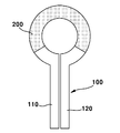
도 1은 본 발명의 일실시예에 따른 카메라 모듈용 박막 히터를 도시한 분해 사시도이다.1 is an exploded perspective view showing a thin film heater for a camera module according to an embodiment of the present invention.
도 1을 참조하면, 카메라 모듈용 박막 히터(400)는 전극(100), 박막 발열체(200) 및 절연 부재(300)를 포함한다.Referring to FIG. 1, a
전극(100)은, 예를 들어, 제1 전극(110) 및 제2 전극(120)을 포함한다.The
제1 전극(110)은, 평면상에서 보았을 때, 박막(thin film) 형태로 형성될 수 있으며, 제1 전극(110)은 도전성이 우수한 소재로 제작될 수 있다.The
예를 들어, 제1 전극(110)으로서 사용될 수 있는 도전성 소재로서는 구리, 구리 합금,알루미늄, 알루미늄 합금 등을 들 수 있다. 이외에도 제1 전극(110)은 제1 전극(110) 자체 저항 성분에 의하여 발열이 가능한 도전성을 갖는 ITO(Indium Thin Oxide) 등으로 제작되어도 무방하다.For example, examples of the conductive material that can be used as the
도 1에 도시된 바와 같이, 제1 전극(110)의 일부는 직선 띠 형상으로 형성될 수 있고, 제1 전극(110)의 일부는 곡면 띠 형상으로 형성될 수 있다.As shown in FIG. 1, a part of the
제2 전극(120)은 제1 전극(110)과 이격 또는 절연된 상태로 배치될 수 있으며, 제2 전극(120)은, 예를 들어, 제1 전극(110)과 대칭 형태로 배치된다.The
제2 전극(120)은, 평면상에서 보았을 때, 박막 형태로 형성될 수 있으며, 제2 전극(120)은 도전성이 우수한 소재로 제작된다.The
예를 들어, 제2 전극(120)으로서 사용될 수 있는 도전성 소재로서는 구리, 구리 합금, 알루미늄, 알루미늄 합금 등을 들 수 있다. 이외에도 제2 전극(120)은 제2 전극(120) 자체 저항 성분에 의하여 발열이 가능한 도전성을 갖는 ITO(Indium Thin Oxide) 등으로 제작되어도 무방하다.For example, examples of the conductive material that can be used as the
본 발명의 일실시예에서, 제1 및 제2 전극(110,120)은 동일한 도전성 소재로 제작되거나 서로 다른 도전성 소재로 제작될 수 있다.In an embodiment of the present invention, the first and
박막 발열체(200)는 박막(thin film) 형태로 제작될 수 있으며, 박막 발열체(200)는 전극(100)에 전기적으로 접속되며, 박막 발열체(200) 및 전극(100)은 일부가 상호 중첩되면서 전기적으로 접속될 수 있다.The thin
본 발명의 일실시예에서, 박막 발열체(200)는, 평면상에서 보았을 때, 일부가 개구된 환형 형상으로 형성될 수 있다.In one embodiment of the present invention, the thin
박막 발열체(200)는 제1 전극(110) 및 제2 전극(120)에 전기적으로 접속될 수 있고, 제1 및 제2 전극(110,120)들을 통해 전원이 박막 발열체(200)로 제공됨에 따라 박막 발열체(200)로부터는 열이 발생된다.The thin
제1 전극(110), 박막 발열체(200) 및 제2 전극(120)이 상호 연결되었을 때, 이들의 형상은, 평면상에서 보았을 때, 환형 링과 유사한 형상으로 형성될 수 있다.When the
박막 발열체(200)는 박막 발열체(200)의 현재 온도 또는 발열 온도에 대응하여 박막 발열체(200)의 전기적 저항이 능동적으로 가변되는 전기적 특성을 갖는다.The thin
본 발명의 일실시예에서, 박막 발열체(200)는 니크롬선(nichrome wire)과 같은 저항 발열체와 다르게 온도가 상승되면 전기 저항이 급격히 증가되고, 반대로 온도가 낮아지면 전기저항이 감소되는 전기적 특성을 갖는다.In an embodiment of the present invention, the temperature of the thin
박막 발열체(200)는 PTC(Positive Temperature Coeffiecient) 물질을 포함할 수 있으며, 반도체 소자 형태로 제작될 수 있다. 본 발명의 일실시예에서, 박막 발열체(200)는 불투명한 소재로 형성된다.The thin
박막 발열체(200)의 작동을 살펴보면, 전극(100)을 통해 박막 발열체(200)에 전원이 제공되면 박막 발열체(200)의 자체 저항에 의하여 발열이 시작되고, 박막 발열체(200)의 발열 온도가 증가됨에 따라 박막 발열체(200)의 전기 저항 역시 증가된다.When power is supplied to the thin
박막 발열체(200)의 저항이 가변되어 박막 발열체(200)의 온도가 특정 온도까지 급격히 상승되면, 박막 발열체(200)의 저항 역시 급격히 증가되기 때문에 박막 발열체(200)의 증가된 저항에 의하여 박막 발열체(200)는 지정된 온도 이상으로 온도가 상승되지 않게 된다.Since the resistance of the thin
한편 박막 발열체(200)의 증가된 저항에 의하여 박막 발열체(200)로의 전원 공급량이 감소되어 박막 발열체(200)의 온도가 낮아질 경우 박막 발열체(200)의 저항도 감소되기 때문에 박막 발열체(200)는 다시 발열 되고 이 과정을 반복하면서 박막 발열체(200)는 일정한 온도 범위 내에서 온도가 일정하게 유지된다.On the other hand, when the power supply to the thin
이와 같이 온도에 능동적으로 반응하여 전기적 저항이 가변되는 박막 발열체(200)는 별도의 온도 센서 및 온도 제어 유닛 없이 목표 온도까지 단 시간내 도달할 수 있고, 목표 온도 이상으로 가열되지 않기 때문에 화재의 위험이 낮으며, 항상 일정한 온도 범위를 유지할 수 있는 장점을 갖는다.Since the thin
이와 같은 다양한 장점을 갖는 박막 발열체(200)는 온도 센서를 장착하기 위한 장소가 협소하고 직접 장착이 어려우며 외기에 의하여 성에, 결로 및 빙결이 빈번히 발생되는 카메라 모듈의 렌즈 등에 적용할 수 있다.The thin
본 발명의 일실시예에서, 박막 발열체(200)의 발열 특성은 전극(100) 및 박막 발열체(200)의 접촉 조건을 변경함으로써 다양하게 변경할 수 있다.In one embodiment of the present invention, the exothermic characteristics of the thin
도 2 내지 도 6은 전극 및 박막 발열체의 다양한 접촉 방식을 도시한 평면도 및 단면도들이다.2 to 6 are a plan view and a sectional view showing various contact methods of the electrode and the thin film heating element.
도 2를 참조하면, 박막 발열체(200)의 일측 단부는 전극(100)의 제1 전극(110)의 단부에 전기적으로 접속되고, 박막 발열체(200)의 일측 단부와 대향하는 타측 단부는 전극(100)의 제2 전극(120)의 단부에 전기적으로 접속된다.2, one end of the thin
도 2의 박막 발열체(200) 및 전극(100)의 접속 구조에서 제1 및 제2 전극(110,120)들 사이의 간격은 상대적으로 길게 형성된다.In the connection structure of the thin
도 3 및 도 4를 참조하면, 제1 전극(110)의 단부에는 제1 전극(110)의 폭보다 좁게 형성된 제1 폭 감소부(115)가 형성되고, 제1 폭 감소부(115)는 제2 전극(120)을 향해 연장된다.3 and 4, a first
제2 전극(120)의 단부에는 제2 전극(120)의 폭보다 좁게 형성된 제2 폭 감소부(125)가 형성되고, 제2 폭 감소부(125)는 제1 전극(110)을 향해 연장된다.A second
제1 전극(110)의 제1 폭 감소부(115) 및 제2 전극(120)의 제2 폭 감소부(125)는 상호 마주하게 배치된다.The first
박막 발열체(200)는 제1 및 제2 폭 감소부(115,125)에 전기적으로 접속된다.The thin
도 3 및 도 4의 박막 발열체(200) 및 전극(100)의 접속 구조에서 제1 및 제2 폭 감소부(115,125)들 사이의 길이는 도 2에 비하여 상대적으로 짧게 형성된다.The length between the first and second
도 5 및 도 6을 참조하면, 제1 전극(110)의 단부는 면적 감소 없이 제2 전극(120)을 향해 연장되고, 제2 전극(120)의 단부는 면적 감소 없이 제1 전극(110)을 향해 연장된다.5 and 6, the end of the
제1 및 제2 전극(110,120)들은 상호 중첩되게 배치되며, 제1 및 제2 전극(110,120)들 사이에는 박막 발열체(200)가 개재된다.The first and
도 5 및 도 6의 박막 발열체(200) 및 전극(100)의 접속 구조에서 제1 및 제2 전극(110,120)들 사이의 길이는 도 3 및 도 4에 비하여 보다 짧게 형성된다.The length between the first and
도 2 내지 도 6에 도시된 바와 같이 박막 발열체(200) 및 전극(100)의 접속 구조를 다양하게 변경시킴으로써 박막 발열체(200)로부터 발생되는 열량을 제어할 수 있다.The amount of heat generated from the thin
도 1을 다시 참조하면, 절연 부재(300)는 전극(100) 및 박막 발열체(200)를 감싸 외부 도전체로부터 전극(100) 및 박막 발열체(200)를 절연하는 역할 및 외부에서 가해진 힘에 의하여 전극(100) 및 박막 발열체(200)의 손상을 방지하는 역할을 한다.1, the insulating
절연 부재(300)는, 예를 들어, 베이스 필름(310) 및 커버 필름(320)을 포함할 수 있다.The insulating
베이스 필름(310) 및 커버 필름(320)의 사이에는 전극(100) 및 전극(100)에 전기적으로 연결된 박막 발열체(200)가 개재되고, 베이스 필름(310) 및 커버 필름(320)이 상호 접합됨으로써 전극(100) 및 박막 발열체(200)는 베이스 필름(310) 및 커버 필름(320) 사이에서 절연된다.A thin
도 1 내지 도 6에 도시된 카메라 모듈용 박막 히터(400)는 가열하고자 하는 대상인 렌즈의 상면 또는 하면에 ITO(Indium Tin Oxide) 물질 등을 포함하는 투명 히팅막이 형성되지 않을 경우 박막 발열체(200)를 이용하여 카메라 모듈의 렌즈와 직접 접촉되어 렌즈를 직접 가열하는 구조에 적합하다.The
한편 가열하고자 하는 대상인 렌즈의 상면 또는 하면에 ITO 물질로 이루어진 투명 히팅막 등이 형성된 경우, 커버 필름(320)에는 투명 히팅막과 전극(100)을 이루는 제1 전극(110) 및 제2 전극(120)을 전기적으로 접속하기 위해 제1 및 제2 전극(110,120)들을 노출하는 개구가 형성될 수 있다.On the other hand, when a transparent heating film made of ITO material is formed on the upper or lower surface of the lens to be heated, the
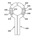
도 7은 본 발명의 다른 실시예에 따른 카메라 모듈용 박막 히터를 도시한 분해 사시도이다.7 is an exploded perspective view illustrating a thin film heater for a camera module according to another embodiment of the present invention.
도 7을 참조하면, 카메라 모듈용 박막 히터(800)는 제1 발열 구조체(525), 제2 발열 구조체(550)를 포함하는 발열 구조체(500) 및 절연 부재(600)를 포함한다. 본 발명의 일실시예에서, 카메라 모듈용 박막 히터(800)는 절연 부재(600)에 추가적으로 배치되는 제3 전극(700)을 더 포함할 수 있다.Referring to FIG. 7, a
제1 발열 구조체(525)는 제1 전극(510) 및 제1 박막 발열체(520)를 포함한다. 제1 전극(510) 및 제1 박막 발열체(520)는 전기적으로 상호 접속된다.The
제1 전극(510)은, 예를 들어, 제1 전극 패턴(512) 및 제2 전극 패턴(514)을 포함한다.The
제1 전극 패턴(512)은, 평면상에서 보았을 때, 박막(thin film) 형태로 형성될 수 있고, 제1 전극 패턴(512)은 도전성이 우수한 소재로 제작될 수 있다.The
예를 들어, 제1 전극 패턴(512)으로서 사용될 수 있는 도전성 소재로서는 구리, 구리 합금,알루미늄, 알루미늄 합금 등을 들 수 있다. 이외에도 제1 전극 패턴(512)은 제1 전극 패턴(512) 자체 저항 성분에 의하여 발열이 가능한 도전성을 갖는 ITO(Indium Thin Oxide) 등으로 제작되어도 무방하다.For example, examples of the conductive material that can be used as the
도 7에 도시된 바와 같이, 제1 전극 패턴(512)의 일부는, 평면상에서 보았을 때, 직선 띠 형상으로 형성되고, 제1 전극 패턴(512)의 일부는, 평면상에서 보았을 때, 곡면 띠 형상으로 형성될 수 있다.7, a part of the
제2 전극 패턴(514)은 제1 전극 패턴(512)과 이격되며, 제2 전극 패턴(514)은 제1 전극패턴(512)과 동일한 도전성 소재로 제작될 수 있다.The
비록 본 발명의 일실시예에서는 제1 및 제2 전극 패턴(512,514)들이 동일한 도전성 소재로 제작되는 것이 설명되고 있지만, 제1 및 제2 전극 패턴(512,514)들은 서로 다른 도전성 소재로 제작되어도 무방하다.Although the first and
제1 박막 발열체(520)는 박막(thin film) 형태로 형성 또는 도포될 수 있고, 제1 박막 발열체(520)는, 평면상에서 보았을 때, 곡면 띠 형상으로 형성될 수 있다.The first thin
제1 박막 발열체(520)는 니크롬선(nichrome wire)과 같은 저항 발열체와 다르게 온도가 상승되면 전기 저항이 급격히 증가되고, 반대로 온도가 낮아지면 전기저항이 감소되는 전기적 특성을 갖는다.The first thin
예를 들어, 제1 박막 발열체(520)는 PTC(Positive Temperature Coeffiecient) 물질을 포함할 수 있으며, 반도체 소자 형태로 제작될 수 있다.For example, the first thin
제1 박막 발열체(520)는 제1 및 제2 전극 패턴(512,514)들 사이에 개재되며, 제1 및 제2 전극 패턴(512,514)들 및 제1 박막 발열체(520)는 상호 전기적으로 접속된다.The first thin
상호 전기적으로 접속된 제1 전극 패턴(512), 제1 박막 발열체(520) 및 제2 전극 패턴(514)을 포함하는 제1 발열 구조체(525)는, 평면상에서 보았을 때, 제1 발열 구조체(525)가 원형 렌즈의 일부를 감싸기에 적합한 반원 띠 형상으로 형성될 수 있다.The
비록 본 발명의 일실싱DP에서, 제1 발열 구조체(525)가 반원 띠 형상으로 형성되는 것이 설명되고 있지만, 제1 발열 구조체(525)는 렌즈의 형상에 따라 변경될 수 있다.Although the
도 7을 다시 참조하면, 제2 발열 구조체(550)는 제2 전극(530) 및 제2 박막 발열체(540)를 포함한다.Referring again to FIG. 7, the
본 발명의 일실시예에서, 제2 발열 구조체(550)는 제1 발열 구조체(525)와 상호 이격되게 배치되며, 제2 발열 구조체(550) 및 제1 발열 구조체(525)는 대칭 형태로 배치될 수 있다.The
제2 발열 구조체(550)의 제2 전극(530) 및 제2 박막 발열체(540)는 상호 전기적으로 접속된다.The
제2 전극(530)은 제3 전극 패턴(532) 및 제4 전극 패턴(534)을 포함한다.The
제3 전극 패턴(532)은, 평면상에서 보았을 때, 박막 형태로 형성될 수 있고, 제3 전극 패턴(532)은 도전성이 우수한 소재로 제작될 수 있다.The
예를 들어, 제3 전극 패턴(532)으로서 사용될 수 있는 도전성 소재로서는 구리, 구리 합금,알루미늄, 알루미늄 합금 등을 들 수 있다. 이외에도 제3 전극 패턴(532)은 제3 전극 패턴(532) 자체 저항 성분에 의하여 발열이 가능한 도전성을 갖는 ITO(Indium Thin Oxide) 등으로 제작되어도 무방하다.For example, examples of the conductive material that can be used as the
도 7에 도시된 바와 같이, 제3 전극 패턴(532)의 일부는 직선 띠 형상으로 형성될 수 있고, 제3 전극 패턴(532)의 일부는 곡면 띠 형상으로 형성될 수 있다.7, a part of the
제4 전극 패턴(534)은 제3 전극 패턴(532)과 이격되며, 제4 전극 패턴(534)은 제3 전극패턴(532)과 동일한 도전성 소재로 제작될 수 있다.The
비록 본 발명의 일실시예에서는 제3 및 제4 전극 패턴(532,534)들이 동일한 도전성 소재로 제작되는 것이 설명되고 있지만, 제3 및 제4 전극 패턴(532,534)들은 서로 다른 도전성 소재로 제작되어도 무방하다.Although the third and
제2 박막 발열체(540)는 박막 형태로 형성될 수 있고, 제2 박막 발열체(540)는 곡면 띠 형상으로 형성될 수 있다.The second thin
제2 박막 발열체(540)는 니크롬선(nichrome wire)과 같은 저항 발열체와 다르게 온도가 상승되면 전기 저항이 급격히 증가되고, 반대로 온도가 낮아지면 전기저항이 감소되는 전기적 특성을 갖는다.The second thin
예를 들어, 제2 박막 발열체(540)는 PTC(Positive Temperature Coeffiecient) 물질을 포함할 수 있으며, 반도체 소자 형태로 제작될 수 있다.For example, the second thin
제2 박막 발열체(540)는 제3 및 제4 전극 패턴(532,534)들의 사이에 개재되며, 제3 및 제4 전극 패턴(532,534)들 및 제2 박막 발열체(540)는 상호 전기적으로 접속된다.The second thin
상호 전기적으로 접속된 제3 전극 패턴(532), 제2 박막 발열체(540) 및 제4 전극 패턴(534)을 포함하는 제2 발열 구조체(550)는, 평면상에서 보았을 때, 제1 발열 구조체(525)가 감싸지 못한 렌즈 모듈의 나머지 부분을 감싸기에 적합한 반원 띠 형상으로 형성된다.The
비록 본 발명의 일실싱DP에서, 제2 발열 구조체(550)가 반원 띠 형상으로 형성되는 것이 설명되고 있지만, 제2 발열 구조체(550)는 렌즈의 형상에 따라 변경될 수 있다.Although the
도 7을 다시 참조하면, 절연 부재(600)는 제1 발열 구조체(525) 및 제2 발열 구조체(550)를 감싸 외부 도전체로부터 제1 발열 구조체(525) 및 제2 발열 구조체(550)를 절연하는 역할 및 외부에서 가해진 힘에 의하여 제1 발열 구조체(525) 및 제2 발열 구조체(550)의 손상을 방지하는 역할을 한다.7, the insulating
절연 부재(600)는, 예를 들어, 베이스 필름(610) 및 커버 필름(620)을 포함할 수 있다.The insulating
베이스 필름(610) 및 커버 필름(620)의 사이에는 제1 발열 구조체(525) 및 제2 발열 구조체(550)가 개재된다.The
베이스 필름(610) 및 커버 필름(620)이 상호 접합됨에 따라 제1 발열 구조체(525) 및 제2 발열 구조체(550)는 베이스 필름(610) 및 커버 필름(620) 사이에서 절연된다.The
본 발명의 일실시예에서, 절연 부재(600)의 커버 필름(620)에는, 예를 들어, 제2 전극 패턴(514) 및 제4 전극 패턴(534)들을 노출하는 개구(625)가 각각 형성된다.An
개구(625)는 제1 발열 구조체(525) 및 제2 발열 구조체(550)를 상호 전기적으로 연결하는 외부 도체 또는 외부 발열체를 연결하기 위해 형성된다. The
비록 본 발명의 일실시예에서는 개구(625)가 커버 필름(620)에 형성된 것이 도시 및 설명되고 있지만, 개구(625)는 베이스 필름(610)에 형성되어도 무방하며, 개구(625)의 위치는 제1 전극 패턴(512) 및 제2 전극 패턴(514)에 형성되어도 무방하다.Although the
절연 부재(600)의 커버 필름(620) 상에는 제3 전극(700)이 배치될 수 있으며, 제3 전극(700)은 개구(625)를 통해 제2 전극 패턴(514) 및 제4 전극 패턴(534)과 전기적으로 접속된다.The
제3 전극(700)은 카메라 모듈에 장착된 렌즈의 상면 또는 하면에 배치된 투명 히팅막과 전기적으로 접속된다.The
본 발명의 일실시예에서, 제3 전극(700) 및 투명 히팅막이 전기적으로 접속됨에 따라 제1 전극(510)으로 제공된 전원은 제1 박막 발열체(520), 투명 히팅막, 제2 전극(530) 및 제2 박막 절연체(540)를 통과 하면서 투명 히팅막, 제1 및 제2 박막 발열체(520,540)에서는 각각 열이 발생된다.The power supplied to the
도 7에 도시된 카메라 모듈용 박막 히터(800)의 제1 발열 구조체(525)에 포함된 제1 박막 발열체(520) 및 제2 발열 구조체(550)에 포함된 제2 박막 발열체(540)는 온도에 능동적으로 반응하여 저항이 가변되기 때문에 별도의 온도 센서 및 온도 제어 유닛 없이 지정된 목표 온도까지 단 시간내 도달할 수 있고, 목표 온도 이상으로 가열되지 않아 화재의 위험이 없으며, 항상 일정한 온도 범위를 유지할 수 있는 장점을 갖는다.The first thin
이와 같은 다양한 장점을 갖는 카메라 모듈용 박막 히터(800)는 온도 센서를 장착하기 위한 장소가 협소하며 외기에 의하여 성에, 결로 및 빙결이 빈번히 발생되는 카메라 모듈의 렌즈에 쉽게 장착할 수 있다.The
본 발명의 일실시예에서, 열을 발생하는 제1 및 제2 박막 발열체(520,540)의 발열 특성은 제1 및 제2 전극 패턴(512,514)과 제1 박막 발열체(520)의 접촉 조건 및 제3 및 제4 전극 패턴(532,534)과 제2 박막 발열체(540)의 접촉 조건을 변경함으로써 다양하게 구현할 수 있다.In one embodiment of the present invention, the heat generating characteristics of the first and second thin
도 8 내지 도 10은 제1 발열 구조체 및 제2 발열 구조체의 다양한 접촉 방식을 도시한 평면도들이다.8 to 10 are plan views showing various contact methods of the first heating structure and the second heating structure.
도 8을 참조하면, 제1 박막 발열체(520)의 일측 단부는 제1 전극(510)의 제1 전극 패턴(512) 및 제1 전극(510)의 제2 전극 패턴(514)에 각각 직렬 방식으로 접촉된다.8, one end of the first thin
도 8의 제1 박막 발열체(520) 및 제1 및 제2 전극 패턴(512,514)들의 접속 구조에서 제1 및 제2 전극 패턴(512,514)들 사이의 간격은 상대적으로 길게 형성된다.The gap between the first and
도 9를 참조하면, 제1 전극(510)의 제1 전극 패턴(512)의 단부에는 제1 전극 패턴(512)의 폭보다 좁게 형성된 제1 폭 감소부(513)가 형성되고, 제1 폭 감소부(513)는 제2 전극 패턴(514)을 향해 연장된다.9, a first
제1 전극(510)의 제2 전극 패턴(514)의 단부에는 제2 전극 패턴(514)의 폭보다 좁게 형성된 제2 폭 감소부(515)가 형성되고, 제2 폭 감소부(515)는 제1 전극 패턴(512)을 향해 연장된다.A second
제1 박막 발열체(520)는 제1 및 제2 폭 감소부(513,515)와 전기적으로 접속된다.The first thin
제2 전극(530)의 제3 전극 패턴(532)의 단부에는 제3 전극 패턴(532)의 폭보다 좁게 형성된 제3 폭 감소부(533)가 형성되고, 제3 폭 감소부(533)는 제4 전극 패턴(534)을 향해 연장된다.A third
제2 전극(530)의 제4 전극 패턴(534)의 단부에는 제4 전극 패턴(534)의 폭보다 좁게 형성된 제4 폭 감소부(535)가 형성되고, 제4 폭 감소부(535)는 제3 전극 패턴(532)을 향해 연장된다.A fourth
제2 박막 발열체(540)는 제3 및 제4 폭 감소부(533,535)들과 전기적으로 접속된다.The second thin
도 9의 접속 구조에서 제1 및 제2 폭 감소부(513,515) 및 제3 및 제4 폭 감소부(533,535)들 사이의 길이는 도 8에 비하여 상대적으로 짧게 형성된다.9, the length between the first and second
도 10을 참조하면, 제1 전극(510)의 제1 전극 패턴(512) 및 제2 전극 패턴(514)은 상호 오버랩되고, 제2 전극(530)의 제3 전극 패턴(532) 및 제4 전극 패턴(534)는 상호 오버랩된다.10, the
상호 오버랩된 제1 전극 패턴(512) 및 제2 전극 패턴(514)들 사이에는 제1 박막 발열체(520)가 개재되고, 상호 오버랩된 제3 전극 패턴(532) 및 제4 전극 패턴(534)의 사이에는 제2 박막 발열체(540)가 개재된다.The first and
도 10의 접속 구조에서 제1 및 제2 전극 패턴(512,514) 및 제3 및 제4 전극 패턴(532,534)들 사이의 길이는 도 9에 비하여 보다 짧게 형성된다.10, the length between the first and
도 8 내지 도 10에 도시된 바와 같이 접속 구조를 다양하게 변경시킴으로써 제1 및 제2 박막 발열체(520,540)로부터 발생되는 열량을 제어할 수 있다.8 to 10, the amount of heat generated from the first and second thin
도 11은 본 발명의 또 다른 실시예에 따른 박막 히터를 포함하는 카메라 모듈의 단면도이다. 도 11에 도시된 카메라용 박막 히터는 앞서 도 1 내지 도 6에 도시 및 설명된 카메라 모듈용 박막 히터(400)와 실질적으로 동일한 구조를 갖는다. 따라서, 동일한 구성에 대한 중복된 설명은 생략하기로 하며, 동일한 구성에 대해서는 동일한 명칭 및 동일한 참조부호를 부여하기로 한다.11 is a cross-sectional view of a camera module including a thin film heater according to another embodiment of the present invention. The thin film heater for a camera shown in Fig. 11 has substantially the same structure as the
도 11을 참조하면, 카메라 모듈(950)은 카메라 모듈 몸체(940), 카메라용 박막 히터(400)를 포함한다.Referring to FIG. 11, the
카메라 모듈 몸체(940)은 수용 공간이 형성된 몸체(910), 몸체(910) 내부에배치된 이미지 센서(920) 및 렌즈(930)를 포함한다.The
본 발명의 일실시예에서, 카메라용 박막 히터(400)는 렌즈(930) 및 몸체(910) 사이에 개재된다.In one embodiment of the present invention, a
카메라용 박막 히터(400)는 전극(100)을 통해 제공된 전원에 의하여 열을 발생시키는 박막 발열체(200)를 포함하며, 박막 발열체(200)는 발열 온도에 대응하여 저항이 가변되는 전기적 특성을 갖는다.The
카메라용 박막 히터(400)는 렌즈(200)에 직접 접촉되어 렌즈(200)에 열을 제공함으로써 성에, 결로 및 빙결이 발생되는 것을 방지할 수 있다.The
카메라용 박막 히터(400) 중 박막 발열체(200)에 전기적으로 연결된 전극(100)의 일부는 몸체(910)의 측면을 따라 몸체(910)의 하부로 연장되고, 전극(100)으로는 외부로부터 전원이 제공된다.A portion of the
도 12는 본 발명의 또 다른 실시예에 따른 박막 히터를 포함하는 카메라 모듈의 단면도이다. 도 12에 도시된 카메라용 박막 히터는 앞서 도 7 내지 도 10에 도시 및 설명된 카메라 모듈용 박막 히터(800)와 실질적으로 동일한 구조를 갖는다. 따라서, 동일한 구성에 대한 중복된 설명은 생략하기로 하며, 동일한 구성에 대해서는 동일한 명칭 및 동일한 참조부호를 부여하기로 한다.12 is a cross-sectional view of a camera module including a thin film heater according to another embodiment of the present invention. The thin film heater for a camera shown in Fig. 12 has substantially the same structure as the
도 12를 참조하면, 카메라 모듈(1000)은 카메라 모듈 몸체(940), 카메라용 박막 히터(800)를 포함한다.Referring to FIG. 12, the
카메라 모듈 몸체(940)은 수용 공간이 형성된 몸체(910), 몸체(910) 내부에배치된 이미지 센서(920) 및 렌즈(930)를 포함한다.The
본 발명의 일실시예에서, 렌즈(930)의 하면에는 투명하면서 전원이 제공되었을 때 열을 발생시키는 투명 히팅막(935)가 형성된다.In an embodiment of the present invention, a
비록 도 12에서 투명 히팅막(935)은 렌즈(930)의 하면에 형성된 것이 도시 및 설명되고 있지만, 투명 히팅막(930)는 렌즈(935)의 상면에 배치되어도 무방하며, 투명 히팅막(935)이 렌즈(930)의 상면에 배치될 경우 투명 히팅막(935)의 일부는 렌즈(930)의 하면으로 연장된다.Although the
본 발명의 일실시예에서, 카메라용 박막 히터(800)는 렌즈(930) 및 몸체(910) 사이에 개재된다.In one embodiment of the present invention, a
카메라용 박막 히터(800)는 제1 발열 구조체(525) 및 제2 발열 구조체(550)를 포함하며, 제1 발열 구조체(525)로 제공된 전원의 일부는 제1 발열 구조체(525), 투명 히팅막(935), 제2 발열 구조체(550)로 제공되며, 이로 인해 투명 히팅막(935)은 가열된다.The camera-use
본 발명의 일실시예에서, 투명 히팅막(935)은 투명하며 전원이 제공됨에 따라 열을 발생하기에 적합한 ITO(Indium Tin Oxide) 물질을 포함할 수 있다.In an embodiment of the present invention, the
투명 히팅막(935)이 가열되는 과정에서 제1 발열 구조체(525)에 포함된 제1 박막 발열체(520) 및 제2 발열 구조체(550)에 포함된 제2 박막 발열체(550)도 함께 가열되며, 제1 및 제2 박막 발열체(520,540)들은 투명 히팅막(935)의 발열을 보조하는 역할을한다.The first thin
카메라용 박막 히터(800)는 렌즈(930)에 직접 형성된 투명 히팅막(935) 및 제1 및 제2 박막 발열체(520,540)들에 열을 복합적으로 제공함으로써 렌즈(930)에 성에, 결로 및 빙결이 발생되는 것을 방지할 수 있다.The camera-use
이상에서 상세하게 설명한 바에 의하면, 빠른 시간 내에 렌즈 모듈을 목표 온도에 도달시켜 성에, 결로 및 빙결을 예방 또는 방지하며, 고온 환경에서 동작되더라도 과열에 의한 화재 발생을 억제하고 온도 센서, 온도 제어 기술 및 콘트롤러가 필요 없어 제조 코스트를 크게 감소시킬 수 있는 효과를 갖는다.As described above in detail, the lens module reaches the target temperature within a short period of time to prevent or prevent glare, condensation and freezing, suppress fire caused by overheating even if operated in a high temperature environment, There is no need for a controller and the manufacturing cost can be greatly reduced.
한편, 본 도면에 개시된 실시예는 이해를 돕기 위해 특정 예를 제시한 것에 지나지 않으며, 본 발명의 범위를 한정하고자 하는 것은 아니다. 여기에 개시된 실시예 이외에도 본 발명의 기술적 사상에 바탕을 둔 다른 변형예들이 실시 가능하다는 것은, 본 발명이 속하는 기술분야에서 통상의 지식을 가진 자에게는 자명한 것이다.
It should be noted that the embodiments disclosed in the drawings are merely examples of specific examples for the purpose of understanding, and are not intended to limit the scope of the present invention. It will be apparent to those skilled in the art that other modifications based on the technical idea of the present invention are possible in addition to the embodiments disclosed herein.
100: 전극
200...박막 발열체
300...절연 부재
400...카메라용 박막 히터100: electrode 200: thin film heating element
300 ...
Claims (17)
상기 전극에 전기적으로 접속되며 발열 온도에 대응하여 저항이 가변되는 박막 발열체; 및
상기 전극 및 상기 박막 발열체를 감싸는 절연 부재를 포함하는 카메라 모듈용 박막 히터.electrode;
A thin film heating element electrically connected to the electrode and having a variable resistance corresponding to a heating temperature; And
And an insulating member surrounding the electrode and the thin film heating element.
상기 전극은 제1 전극 및 상기 제1 전극과 이격된 제2 전극을 포함하고,
상기 박막 발열체는 상기 제1 전극 및 상기 제2 전극의 단부에 전기적으로 접속된 카메라 모듈용 박막 히터.The method according to claim 1,
Wherein the electrode comprises a first electrode and a second electrode spaced from the first electrode,
Wherein the thin film heating element is electrically connected to the ends of the first electrode and the second electrode.
상기 전극은 제1 전극 및 상기 제1 전극과 이격된 제2 전극을 포함하고,
상기 제1 전극은 폭이 감소되는 제1 폭 감소부를 포함하고, 상기 제2 전극은 폭이 감소되는 제2 폭 감소부를 포함하며, 상기 박막 발열체는 상기 제1 및 제2 폭 감소부들에 전기적으로 접속된 카메라 모듈용 박막 히터.The method according to claim 1,
Wherein the electrode comprises a first electrode and a second electrode spaced from the first electrode,
Wherein the first electrode includes a first width decreasing portion whose width is decreased and the second electrode includes a second width decreasing portion whose width is decreased and the thin film heating element is electrically connected to the first and second width reducing portions Thin film heater for connected camera module.
상기 전극은 제1 전극 및 상기 제1 전극과 이격된 제2 전극을 포함하고,
상기 제1 전극의 일부 및 상기 제2 전극의 일부는 상호 중첩되고, 상기 박막 발열체는 상기 제1 및 제2 전극들의 사이에 개재되는 카메라 모듈용 박막 히터.The method according to claim 1,
Wherein the electrode comprises a first electrode and a second electrode spaced from the first electrode,
Wherein a part of the first electrode and a part of the second electrode overlap each other and the thin film heating element is interposed between the first and second electrodes.
상기 절연 부재는 상기 전극 및 상기 박막 발열체가 배치되는 베이스 필름 및 상기 베이스 필름과 접합되는 커버 필름을 포함하는 카메라 모듈용 박막 발열체.The method according to claim 1,
Wherein the insulating member includes a base film on which the electrode and the thin film heating element are disposed, and a cover film bonded to the base film.
상기 제1 발열 구조체와 절연되며, 제2 전극과 전기적으로 연결되어 발열 온도에 대응하여 저항이 가변되는 제2 박막 발열체를 포함하는 제2 발열 구조체; 및
상기 제1 및 제2 발열 구조체들을 절연하며 상기 제1 및 제2 전극의 일부를 노출하는 개구를 갖는 절연 부재를 포함하는 카메라 모듈용 박막 히터.A first heating structure including a first thin film heating element electrically connected to the first electrode and having a variable resistance corresponding to a heating temperature;
A second heating structure including a second thin film heating element insulated from the first heating structure and electrically connected to the second electrode, the second thin film heating element having a variable resistance corresponding to a heating temperature; And
And an insulating member insulating the first and second heating structures and having an opening exposing a part of the first and second electrodes.
상기 절연 부재의 외측면에 배치되며 상기 개구를 통해 상기 제1 및 제2 전극들과 전기적으로 접속되는 제3 전극들을 더 포함하는 카메라 모듈용 박막 히터.The method according to claim 6,
And third electrodes disposed on an outer surface of the insulating member and electrically connected to the first and second electrodes through the opening.
상기 제3 전극들은 카메라 렌즈를 덮는 투명 히터막과 전기적으로 접속되는 카메라 모듈용 박막 히터.The method according to claim 6,
And the third electrodes are electrically connected to a transparent heater film covering the camera lens.
상기 제1 전극은 상기 제1 박막 발열체와 전기적으로 접속된 제1 전극 패턴 및 제2 전극 패턴을 포함하고, 상기 제2 전극은 상기 제2 박막 발열체와 전기적으로 접속된 제3 전극 패턴 및 제4 전극 패턴을 포함하는 카메라 모듈용 박막 히터.The method according to claim 6,
Wherein the first electrode includes a first electrode pattern and a second electrode pattern electrically connected to the first thin film heating element, the second electrode includes a third electrode pattern electrically connected to the second thin film heating element, A thin film heater for a camera module comprising an electrode pattern.
상기 제1 전극은 상기 제1 박막 발열체와 전기적으로 접속되는 제1 전극 패턴 및 제2 전극 패턴을 포함하고, 상기 제2 전극은 상기 제2 박막 발열체와 전기적으로 접속된 제3 전극 패턴 및 제4 전극 패턴을 포함하며,
상기 제1 및 제2 전극 패턴들은 폭이 감소되는 제1 폭 감소부들을 포함하고, 상기 제3 및 제4 전극 패턴들은 폭이 감소되는 제2 폭 감소부들을 포함하며,
상기 제1 박막 발열체들은 상기 제1 및 제2 폭 감소부들에 전기적으로 접속되고, 상기 제2 박막 발열체들은 상기 제3 및 제4 전극패턴들에 전기적으로 접속된 카메라 모듈용 박막 히터.The method according to claim 6,
Wherein the first electrode includes a first electrode pattern and a second electrode pattern electrically connected to the first thin film heating element, the second electrode includes a third electrode pattern electrically connected to the second thin film heating element, Electrode pattern,
Wherein the first and second electrode patterns include first width reduction portions whose widths are reduced and the third and fourth electrode patterns include second width reduction portions whose widths are reduced,
Wherein the first thin film heating elements are electrically connected to the first and second width reducing portions and the second thin film heating elements are electrically connected to the third and fourth electrode patterns.
상기 제1 전극은 제1 전극 패턴 및 상기 제1 전극 패턴과 오버랩된 제2 전극 패턴을 포함하고, 상기 제2 전극은 제3 전극 패턴 및 상기 제3 전극 패턴과 오버랩된 제4 전극 패턴을 포함하며,
상기 제1 박막 발열체는 상기 제1 및 제2 전극 패턴들 사이에 개재되고, 상기 제2 박막 발열체는 상기 제3 및 제4 전극 패턴들 사이에 개재되는 카메라 모듈용 박막 히터.The method according to claim 6,
The first electrode includes a first electrode pattern and a second electrode pattern overlapping the first electrode pattern. The second electrode includes a third electrode pattern and a fourth electrode pattern overlapping the third electrode pattern. In addition,
Wherein the first thin film heating element is interposed between the first and second electrode patterns and the second thin film heating element is interposed between the third and fourth electrode patterns.
상기 절연 부재는 상기 제1 및 제2 전극, 상기 제1 및 제2 발열 구조체들이 배치되는 베이스 필름 및 상기 베이스 필름과 접합되며 상기 개구들이 형성된 커버 필름을 포함하는 카메라 모듈용 박막 히터.The method according to claim 6,
Wherein the insulating member comprises a base film on which the first and second electrodes, the first and second heating structures are disposed, and a cover film joined to the base film and having the openings formed therein.
전극, 상기 전극에 전기적으로 접속되며 발열 온도에 대응하여 저항이 가변되며 상기 렌즈의 주변에 배치된 적어도 하나의 박막 발열체 및 상기 전극 및 상기 박막 발열체를 감싸는 절연 부재를 포함하는 박막 히터를 포함는 카메라 모듈.A camera module body including an image sensor and a lens disposed on an optical axis of the image sensor; And
And a thin film heater electrically connected to the electrode, the thin film heater including at least one thin film heating element disposed around the lens and having a variable resistance corresponding to a heating temperature, and an insulating member surrounding the electrode and the thin film heating element. .
상기 전극의 일부는 상기 카메라 모듈 몸체의 측면을 따라 연장되어 외부 단자와 전기적으로 접속된 카메라 모듈.14. The method of claim 13,
And a portion of the electrode extends along a side surface of the camera module body and is electrically connected to an external terminal.
상기 렌즈와 접촉되고 제1 전극과 전기적으로 연결되며 발열 온도에 대응하여 저항이 가변되는 제1 박막 발열체를 포함하는 제1 발열 구조체, 상기 제1 발열 구조체와 절연되며 제2 전극과 전기적으로 연결되어 발열 온도에 대응하여 저항이 가변되는 제2 박막 발열체를 포함하는 제2 발열 구조체 및 상기 제1 및 제2 발열 구조체들을 절연하며 상기 제1 및 제2 전극의 일부를 노출하는 개구를 갖는 절연 부재; 및
상기 제1 전극 및 상기 투명 히팅막을 전기적을 접속 및 상기 제2 전극 및 상기 투명 히팅막을 전기적으로 접속하는 제3 전극들을 포함하는 카메라 모듈.A camera module body including an image sensor, a lens disposed on an optical axis of the image sensor, and a transparent heating film covering the lens;
A first heating structure including a first thin film heating element which is in contact with the lens and is electrically connected to the first electrode and has a variable resistance corresponding to a heating temperature, and a second heating structure which is electrically insulated from the first heating structure and electrically connected to the second electrode A second heating structure including a second thin film heating element whose resistance varies in response to an exothermic temperature, and an insulating member insulated from the first and second heating structures and having an opening exposing a part of the first and second electrodes; And
And third electrodes electrically connecting the first electrode and the transparent heating film and electrically connecting the second electrode and the transparent heating film.
상기 투명 히팅막은 ITO(Indium Tin Oxide)를 포함하는 카메라 모듈.16. The method of claim 15,
Wherein the transparent heating film includes indium tin oxide (ITO).
상기 투명 히팅막은 상기 박막 히터와 마주하는 상기 렌즈의 하면에 배치된 카메라 모듈.16. The method of claim 15,
Wherein the transparent heating film is disposed on a lower surface of the lens facing the thin film heater.
Priority Applications (7)
| Application Number | Priority Date | Filing Date | Title |
|---|---|---|---|
| KR1020150130091A KR102487620B1 (en) | 2015-09-15 | 2015-09-15 | Thin film type heater for camera module and camera module having the same |
| US15/760,528 US11143864B2 (en) | 2015-09-15 | 2016-09-12 | Camera module thin film heater |
| PCT/KR2016/010261 WO2017048014A1 (en) | 2015-09-15 | 2016-09-12 | Camera module thin film heater and camera module having same |
| EP21175344.7A EP3913432A3 (en) | 2015-09-15 | 2016-09-12 | Camera module thin film heater and camera module having same |
| CN201680053695.7A CN108027548B (en) | 2015-09-15 | 2016-09-12 | Camera module film heater and camera module |
| EP16846835.3A EP3352008B1 (en) | 2015-09-15 | 2016-09-12 | Camera module thin film heater and camera module having same |
| KR1020230002433A KR20230010268A (en) | 2015-09-15 | 2023-01-06 | Thin film type heater for camera module and camera module having the same |
Applications Claiming Priority (1)
| Application Number | Priority Date | Filing Date | Title |
|---|---|---|---|
| KR1020150130091A KR102487620B1 (en) | 2015-09-15 | 2015-09-15 | Thin film type heater for camera module and camera module having the same |
Related Child Applications (1)
| Application Number | Title | Priority Date | Filing Date |
|---|---|---|---|
| KR1020230002433A Division KR20230010268A (en) | 2015-09-15 | 2023-01-06 | Thin film type heater for camera module and camera module having the same |
Publications (2)
| Publication Number | Publication Date |
|---|---|
| KR20170032585A true KR20170032585A (en) | 2017-03-23 |
| KR102487620B1 KR102487620B1 (en) | 2023-01-12 |
Family
ID=58289532
Family Applications (2)
| Application Number | Title | Priority Date | Filing Date |
|---|---|---|---|
| KR1020150130091A KR102487620B1 (en) | 2015-09-15 | 2015-09-15 | Thin film type heater for camera module and camera module having the same |
| KR1020230002433A KR20230010268A (en) | 2015-09-15 | 2023-01-06 | Thin film type heater for camera module and camera module having the same |
Family Applications After (1)
| Application Number | Title | Priority Date | Filing Date |
|---|---|---|---|
| KR1020230002433A KR20230010268A (en) | 2015-09-15 | 2023-01-06 | Thin film type heater for camera module and camera module having the same |
Country Status (5)
| Country | Link |
|---|---|
| US (1) | US11143864B2 (en) |
| EP (2) | EP3352008B1 (en) |
| KR (2) | KR102487620B1 (en) |
| CN (1) | CN108027548B (en) |
| WO (1) | WO2017048014A1 (en) |
Cited By (6)
| Publication number | Priority date | Publication date | Assignee | Title |
|---|---|---|---|---|
| CN107181902A (en) * | 2017-07-11 | 2017-09-19 | 信利光电股份有限公司 | One kind shooting epicranial plate and camera |
| WO2020111365A1 (en) * | 2018-11-30 | 2020-06-04 | 에이치엔티일렉트로닉스(주) | Camera module having heating function and manufacturing method therefor |
| WO2020130706A1 (en) * | 2018-12-21 | 2020-06-25 | 엘지이노텍(주) | Camera module including liquid lens, and method for controlling same |
| WO2020197289A1 (en) * | 2019-03-26 | 2020-10-01 | 엘지이노텍 주식회사 | Heating device and camera module |
| WO2020242178A1 (en) * | 2019-05-31 | 2020-12-03 | 엘지이노텍 주식회사 | Camera module |
| WO2021054775A1 (en) * | 2019-09-18 | 2021-03-25 | 주식회사 아이엠첨단소재 | Heating device and vehicle camera using same |
Families Citing this family (20)
| Publication number | Priority date | Publication date | Assignee | Title |
|---|---|---|---|---|
| KR102524129B1 (en) * | 2016-02-15 | 2023-04-21 | 엘지이노텍 주식회사 | Heating device for camera module and camera module having the same |
| JP6723194B2 (en) * | 2017-04-26 | 2020-07-15 | 株式会社東海理化電機製作所 | Imaging device |
| JP2019046786A (en) * | 2017-09-04 | 2019-03-22 | 株式会社デンソー | Heater device |
| KR102123677B1 (en) * | 2018-08-21 | 2020-06-17 | 엘지전자 주식회사 | Electric Heater |
| JP7293969B2 (en) * | 2018-10-25 | 2023-06-20 | 株式会社デンソー | heater device |
| US11453366B2 (en) * | 2018-11-06 | 2022-09-27 | Motherson Innovations Company Limited | Heatable device for use with a vehicle-mounted image acquisition unit |
| JP7339023B2 (en) | 2019-06-07 | 2023-09-05 | マクセル株式会社 | Lens unit and camera module |
| WO2020253541A1 (en) * | 2019-06-17 | 2020-12-24 | 宁波舜宇车载光学技术有限公司 | Optical device and use thereof |
| JP2021012352A (en) * | 2019-07-09 | 2021-02-04 | パナソニックi−PROセンシングソリューションズ株式会社 | Surveillance camera and cover |
| US20210160969A1 (en) * | 2019-11-22 | 2021-05-27 | Honeywell International Inc. | Window heating apparatus |
| CN111983766A (en) * | 2019-12-31 | 2020-11-24 | 江西联创电子有限公司 | Optical lens and imaging module |
| US11927747B2 (en) | 2019-12-31 | 2024-03-12 | Jiangxi Lianchuang Electronic Co., Ltd. | Camera module, vehicle camera and monitoring system |
| DE102020200695A1 (en) * | 2020-01-22 | 2021-07-22 | Robert Bosch Gesellschaft mit beschränkter Haftung | Camera module |
| US11650391B2 (en) * | 2020-02-25 | 2023-05-16 | Littelfuse, Inc. | PPTC heater and material having stable power and self-limiting behavior |
| US20210400179A1 (en) * | 2020-06-18 | 2021-12-23 | Ford Global Technologies, Llc | Sensor system with cleaning and heating |
| SE2050801A1 (en) * | 2020-06-30 | 2021-12-31 | Orlaco Products B V | Camera system with lens heater |
| KR102483614B1 (en) * | 2020-09-01 | 2023-01-02 | 삼성전기주식회사 | Camera Module |
| CN117642672A (en) * | 2021-07-02 | 2024-03-01 | 泰立戴恩菲力尔商业系统公司 | Heating camera and related method |
| EP4123357A1 (en) * | 2021-07-23 | 2023-01-25 | Ficosa Adas, S.L.U. | Lens assembly, camera module having a lens assembly for motor vehicles, and a method for making a lens assembly |
| JP2023023904A (en) * | 2021-08-06 | 2023-02-16 | マクセル株式会社 | Heater, lens unit, camera module, on-vehicle system, mobile body, and method for incorporating heater |
Citations (6)
| Publication number | Priority date | Publication date | Assignee | Title |
|---|---|---|---|---|
| JPH0738788A (en) | 1993-07-22 | 1995-02-07 | Sharp Corp | Camera monitor device |
| KR200342920Y1 (en) * | 2003-12-02 | 2004-02-19 | (주)동화이엔지 | camera with conductive heating film |
| KR200424379Y1 (en) * | 2006-06-07 | 2006-08-22 | 김종만 | Window having transparent heater film |
| JP2006525897A (en) * | 2003-05-22 | 2006-11-16 | フィコ ミロールス,エセ ア | Image acquisition unit having a heating device for monitoring the outside of a vehicle |
| JP2007108191A (en) * | 2005-10-11 | 2007-04-26 | Citizen Electronics Co Ltd | Liquid crystal lens apparatus |
| KR101462983B1 (en) * | 2013-09-27 | 2014-11-18 | 한국생산기술연구원 | Closed Circuit Television Camera employing transparent heating sheet |
Family Cites Families (18)
| Publication number | Priority date | Publication date | Assignee | Title |
|---|---|---|---|---|
| US4309596A (en) * | 1980-06-24 | 1982-01-05 | Sunbeam Corporation | Flexible self-limiting heating cable |
| DE3144275C1 (en) * | 1981-11-07 | 1983-04-14 | Grundig E.M.V. Elektro-Mechanische Versuchsanstalt Max Grundig & Co KG, 8510 Fürth | "Compact television camera for indoor or outdoor use" |
| DE4436087C2 (en) * | 1994-10-10 | 2003-06-18 | Siedle & Soehne S | Heating device for a translucent protective pane of a protective housing of a camera |
| DE29514364U1 (en) * | 1995-09-07 | 1996-01-18 | Hohe Gmbh & Co Kg | Image acquisition module |
| JPH11231696A (en) * | 1998-02-10 | 1999-08-27 | Canon Inc | Heating body, heating device and image forming device |
| JP2001066934A (en) * | 1999-08-27 | 2001-03-16 | Canon Inc | Heating device and image forming device |
| US7480149B2 (en) * | 2004-08-18 | 2009-01-20 | Donnelly Corporation | Accessory module for vehicle |
| DE10340900A1 (en) * | 2003-09-02 | 2005-03-24 | Valeo Schalter Und Sensoren Gmbh | Camera module with heated cover disc for monitoring car rear environment and stationary monitoring of buildings, house entrances, public places etc., containing lens, evaluator, |
| KR20070018642A (en) * | 2005-08-10 | 2007-02-14 | 엘지전자 주식회사 | A method and a structure and a device of remove dampness on window for camera object lens |
| US20100084161A1 (en) * | 2008-10-08 | 2010-04-08 | Robert A. Neal | Conductive film and process for making same |
| DE102008063849A1 (en) * | 2008-12-19 | 2010-06-24 | Tesa Se | Heated surface element and method for its attachment |
| KR20100094838A (en) * | 2009-02-19 | 2010-08-27 | (주)씨프로 | A camera for preventing a humidity |
| JP5344346B2 (en) * | 2009-12-02 | 2013-11-20 | 山本光学株式会社 | Anti-fogging lenses and eye protection |
| KR20110068442A (en) * | 2009-12-16 | 2011-06-22 | 주식회사 오카스 | Heater for protecting frost of camera window and drive system thereof |
| JPWO2012063473A1 (en) * | 2010-11-08 | 2014-05-12 | パナソニック株式会社 | Planar heating element and manufacturing method thereof |
| TWM408051U (en) * | 2011-01-04 | 2011-07-21 | Topview Optronics Corp | Defogging and defrosting device for camera protection lens |
| US9210739B2 (en) * | 2012-06-26 | 2015-12-08 | Iee International Electronics & Engineering S.A. | PTC heating device without electronic power control |
| JP6071366B2 (en) | 2012-09-19 | 2017-02-01 | キヤノン株式会社 | Heater and image heating apparatus equipped with the heater |
-
2015
- 2015-09-15 KR KR1020150130091A patent/KR102487620B1/en active IP Right Grant
-
2016
- 2016-09-12 US US15/760,528 patent/US11143864B2/en active Active
- 2016-09-12 EP EP16846835.3A patent/EP3352008B1/en active Active
- 2016-09-12 WO PCT/KR2016/010261 patent/WO2017048014A1/en active Application Filing
- 2016-09-12 CN CN201680053695.7A patent/CN108027548B/en active Active
- 2016-09-12 EP EP21175344.7A patent/EP3913432A3/en active Pending
-
2023
- 2023-01-06 KR KR1020230002433A patent/KR20230010268A/en active IP Right Grant
Patent Citations (6)
| Publication number | Priority date | Publication date | Assignee | Title |
|---|---|---|---|---|
| JPH0738788A (en) | 1993-07-22 | 1995-02-07 | Sharp Corp | Camera monitor device |
| JP2006525897A (en) * | 2003-05-22 | 2006-11-16 | フィコ ミロールス,エセ ア | Image acquisition unit having a heating device for monitoring the outside of a vehicle |
| KR200342920Y1 (en) * | 2003-12-02 | 2004-02-19 | (주)동화이엔지 | camera with conductive heating film |
| JP2007108191A (en) * | 2005-10-11 | 2007-04-26 | Citizen Electronics Co Ltd | Liquid crystal lens apparatus |
| KR200424379Y1 (en) * | 2006-06-07 | 2006-08-22 | 김종만 | Window having transparent heater film |
| KR101462983B1 (en) * | 2013-09-27 | 2014-11-18 | 한국생산기술연구원 | Closed Circuit Television Camera employing transparent heating sheet |
Cited By (7)
| Publication number | Priority date | Publication date | Assignee | Title |
|---|---|---|---|---|
| CN107181902A (en) * | 2017-07-11 | 2017-09-19 | 信利光电股份有限公司 | One kind shooting epicranial plate and camera |
| WO2020111365A1 (en) * | 2018-11-30 | 2020-06-04 | 에이치엔티일렉트로닉스(주) | Camera module having heating function and manufacturing method therefor |
| WO2020130706A1 (en) * | 2018-12-21 | 2020-06-25 | 엘지이노텍(주) | Camera module including liquid lens, and method for controlling same |
| WO2020197289A1 (en) * | 2019-03-26 | 2020-10-01 | 엘지이노텍 주식회사 | Heating device and camera module |
| WO2020242178A1 (en) * | 2019-05-31 | 2020-12-03 | 엘지이노텍 주식회사 | Camera module |
| WO2021054775A1 (en) * | 2019-09-18 | 2021-03-25 | 주식회사 아이엠첨단소재 | Heating device and vehicle camera using same |
| KR20210033361A (en) * | 2019-09-18 | 2021-03-26 | 주식회사 아이엠첨단소재 | Heating device and camera for vehicles using the same |
Also Published As
| Publication number | Publication date |
|---|---|
| US11143864B2 (en) | 2021-10-12 |
| KR102487620B1 (en) | 2023-01-12 |
| EP3352008A4 (en) | 2018-09-05 |
| US20190041630A1 (en) | 2019-02-07 |
| CN108027548A (en) | 2018-05-11 |
| EP3913432A2 (en) | 2021-11-24 |
| EP3913432A3 (en) | 2022-03-23 |
| WO2017048014A1 (en) | 2017-03-23 |
| EP3352008B1 (en) | 2021-06-30 |
| EP3352008A1 (en) | 2018-07-25 |
| KR20230010268A (en) | 2023-01-18 |
| CN108027548B (en) | 2021-11-26 |
Similar Documents
| Publication | Publication Date | Title |
|---|---|---|
| KR102487620B1 (en) | Thin film type heater for camera module and camera module having the same | |
| CN100373268C (en) | Overheat protection device for movable body surface, overheat protection apparatus using the same and temperarture control device | |
| TWI528407B (en) | Complex protection device for blocking abnormal state of current and voltage | |
| US20150364286A1 (en) | Complex protection device | |
| JP6813715B2 (en) | Plane heating element and windshield device for vehicles | |
| JP6017603B2 (en) | Composite protective element | |
| EP2013887A2 (en) | Wound capacitor having a thermal disconnect at a hot spot | |
| JP5443587B2 (en) | Sensor device and production method | |
| CN113632000A (en) | Heating device and camera module | |
| JP2014506669A (en) | Sensor heater, heated radiation sensor, and radiation detection method | |
| KR102174814B1 (en) | Assembly for connecting a flat plate to a voltage source with a built-in control unit | |
| TWI528406B (en) | Complex protection device for blocking abnormal state of current and voltage | |
| JP5853312B2 (en) | Resistor | |
| JP2021086837A (en) | Chip resistor | |
| TWI547967B (en) | Complex protection device | |
| JP2010061894A (en) | Resistor with temperature fuse | |
| TWI805729B (en) | Thermal varistor protection device | |
| JP3219722U (en) | heater | |
| WO2023276464A1 (en) | Planar heating element, optical device, and method for manufacturing planar heating element | |
| JP2011175837A (en) | Ceramic heater | |
| JP6511691B2 (en) | Water tank heater | |
| JP2023006588A (en) | Planar heating element, optical device, and method for manufacturing planar heating element | |
| JP2020119860A (en) | Heater and camera module | |
| JP2022024237A (en) | Heater unit and application thereof | |
| JPS6353903A (en) | Power type resistor |
Legal Events
| Date | Code | Title | Description |
|---|---|---|---|
| A201 | Request for examination | ||
| E902 | Notification of reason for refusal | ||
| E902 | Notification of reason for refusal | ||
| E701 | Decision to grant or registration of patent right |