EP3913323A1 - Feeding device of hole inspection device and corresponding feeding method - Google Patents
Feeding device of hole inspection device and corresponding feeding method Download PDFInfo
- Publication number
- EP3913323A1 EP3913323A1 EP21168156.4A EP21168156A EP3913323A1 EP 3913323 A1 EP3913323 A1 EP 3913323A1 EP 21168156 A EP21168156 A EP 21168156A EP 3913323 A1 EP3913323 A1 EP 3913323A1
- Authority
- EP
- European Patent Office
- Prior art keywords
- hole
- inspection device
- positioning
- probe
- hole inspection
- Prior art date
- Legal status (The legal status is an assumption and is not a legal conclusion. Google has not performed a legal analysis and makes no representation as to the accuracy of the status listed.)
- Granted
Links
Images



Classifications
-
- G—PHYSICS
- G01—MEASURING; TESTING
- G01B—MEASURING LENGTH, THICKNESS OR SIMILAR LINEAR DIMENSIONS; MEASURING ANGLES; MEASURING AREAS; MEASURING IRREGULARITIES OF SURFACES OR CONTOURS
- G01B11/00—Measuring arrangements characterised by the use of optical techniques
- G01B11/08—Measuring arrangements characterised by the use of optical techniques for measuring diameters
- G01B11/12—Measuring arrangements characterised by the use of optical techniques for measuring diameters internal diameters
-
- G—PHYSICS
- G01—MEASURING; TESTING
- G01B—MEASURING LENGTH, THICKNESS OR SIMILAR LINEAR DIMENSIONS; MEASURING ANGLES; MEASURING AREAS; MEASURING IRREGULARITIES OF SURFACES OR CONTOURS
- G01B5/00—Measuring arrangements characterised by the use of mechanical techniques
- G01B5/0002—Arrangements for supporting, fixing or guiding the measuring instrument or the object to be measured
- G01B5/0004—Supports
-
- B—PERFORMING OPERATIONS; TRANSPORTING
- B23—MACHINE TOOLS; METAL-WORKING NOT OTHERWISE PROVIDED FOR
- B23Q—DETAILS, COMPONENTS, OR ACCESSORIES FOR MACHINE TOOLS, e.g. ARRANGEMENTS FOR COPYING OR CONTROLLING; MACHINE TOOLS IN GENERAL CHARACTERISED BY THE CONSTRUCTION OF PARTICULAR DETAILS OR COMPONENTS; COMBINATIONS OR ASSOCIATIONS OF METAL-WORKING MACHINES, NOT DIRECTED TO A PARTICULAR RESULT
- B23Q17/00—Arrangements for observing, indicating or measuring on machine tools
- B23Q17/24—Arrangements for observing, indicating or measuring on machine tools using optics or electromagnetic waves
-
- G—PHYSICS
- G01—MEASURING; TESTING
- G01B—MEASURING LENGTH, THICKNESS OR SIMILAR LINEAR DIMENSIONS; MEASURING ANGLES; MEASURING AREAS; MEASURING IRREGULARITIES OF SURFACES OR CONTOURS
- G01B11/00—Measuring arrangements characterised by the use of optical techniques
- G01B11/24—Measuring arrangements characterised by the use of optical techniques for measuring contours or curvatures
-
- G—PHYSICS
- G01—MEASURING; TESTING
- G01B—MEASURING LENGTH, THICKNESS OR SIMILAR LINEAR DIMENSIONS; MEASURING ANGLES; MEASURING AREAS; MEASURING IRREGULARITIES OF SURFACES OR CONTOURS
- G01B11/00—Measuring arrangements characterised by the use of optical techniques
- G01B11/30—Measuring arrangements characterised by the use of optical techniques for measuring roughness or irregularity of surfaces
- G01B11/303—Measuring arrangements characterised by the use of optical techniques for measuring roughness or irregularity of surfaces using photoelectric detection means
-
- G—PHYSICS
- G01—MEASURING; TESTING
- G01B—MEASURING LENGTH, THICKNESS OR SIMILAR LINEAR DIMENSIONS; MEASURING ANGLES; MEASURING AREAS; MEASURING IRREGULARITIES OF SURFACES OR CONTOURS
- G01B21/00—Measuring arrangements or details thereof, where the measuring technique is not covered by the other groups of this subclass, unspecified or not relevant
- G01B21/02—Measuring arrangements or details thereof, where the measuring technique is not covered by the other groups of this subclass, unspecified or not relevant for measuring length, width, or thickness
- G01B21/04—Measuring arrangements or details thereof, where the measuring technique is not covered by the other groups of this subclass, unspecified or not relevant for measuring length, width, or thickness by measuring coordinates of points
- G01B21/047—Accessories, e.g. for positioning, for tool-setting, for measuring probes
-
- B—PERFORMING OPERATIONS; TRANSPORTING
- B23—MACHINE TOOLS; METAL-WORKING NOT OTHERWISE PROVIDED FOR
- B23B—TURNING; BORING
- B23B49/00—Measuring or gauging equipment on boring machines for positioning or guiding the drill; Devices for indicating failure of drills during boring; Centering devices for holes to be bored
- B23B49/001—Devices for detecting or indicating failure of drills
-
- B—PERFORMING OPERATIONS; TRANSPORTING
- B23—MACHINE TOOLS; METAL-WORKING NOT OTHERWISE PROVIDED FOR
- B23B—TURNING; BORING
- B23B49/00—Measuring or gauging equipment on boring machines for positioning or guiding the drill; Devices for indicating failure of drills during boring; Centering devices for holes to be bored
- B23B49/02—Boring templates or bushings
Definitions
- Embodiments of the invention as described herein relate generally to a feeding device of a hole inspection device, a hole inspection unit and a method of feeding a hole inspection device.
- a hole is processed on an object by a drilling tool, such as a drill
- a drilling tool such as a drill
- a contact measuring method in which a contact-type probe is moved while contacting the probe on the inside surface of the hole
- a non-contact measuring method in which the inside surface of the hole is irradiated with laser light and interference light is analyzed, are known (for example, refer to Japanese Patent Application Publication JP 2014 - 115144 A ).
- the conventional method of inspecting features of a hole requires to set an object having the hole to be inspected at a right position in a three dimensional measuring device or the like. Accordingly, when the object has been drilled by a handheld drilling device, the feature of the hole cannot be inspected promptly.
- an object of the present invention is to make it possible to inspect a feature, such as surface roughness and/or a shape, of a hole to be inspected without setting an object having the hole on a measuring device.
- a feeding device of a hole inspection device having a probe, and includes an attaching jig, a movement mechanism, and a positioning jig.
- the probe is inserted into a hole to be inspected of an object in a central axis direction of the hole, for inspecting the hole.
- the attaching jig attaches the hole inspection device to the feeding device.
- the movement mechanism linearly reciprocates the hole inspection device together with the attaching jig.
- the positioning jig positions the movement mechanism to the object.
- a moving direction of the attaching jig and the hole inspection device is made parallel to the central axis direction of the hole by positioning the movement mechanism.
- a hole inspection unit includes the above-mentioned feeding device and the above-mentioned hole inspection device.
- a method of feeding a hole inspection device having a probe, for inspecting a hole to be inspected of an object by inserting the prove in a central axis direction of the hole which method includes the following steps: attaching the hole inspection device to an attaching jig; positioning a movement mechanism to the object by a positioning jig; and feeding the hole inspection device by linearly advancing the attaching jig together with the hole inspection device toward the object by the movement mechanism.
- the movement mechanism linearly reciprocates the hole inspection device together with the attaching jig.
- a moving direction of the attaching jig and the hole inspection device is made parallel to the central axis direction of the hole by positioning the movement mechanism.
- a feeding device of a hole inspection device, a hole inspection unit and a method of feeding a hole inspection device according to embodiments of the present invention will be described with reference to the accompanying drawings.
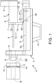
- FIG. 1 is a front view of a hole inspection unit according to the first embodiment of the present invention
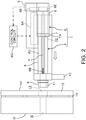
- FIG. 2 is a top view of the hole inspection unit shown in FIG. 1
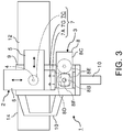
- FIG. 3 is a right side view of the hole inspection unit shown in FIG. 1
- FIG. 4 is a front view of the hole inspection unit shown in FIG. 1 in a state where a hole is being inspected by setting the hole inspection unit
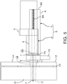
- FIG. 5 is a top view of the hole inspection unit shown in FIG. 4 .
- a hole inspection unit 1 is a handheld device for inspecting at least one feature of a hole H formed in an object O.
- the hole H to be inspected may be a through hole, or may be a blind hole.
- Concrete examples of the features of the hole H to be inspected include diameters at respective depths of the hole H, surface roughness at respective positions on the inside surface of the hole H, the existence of a damage on the inside surface of the hole H, and a three dimensional shape of the inside surface of the hole H.
- an edge of the hole H may also be inspected regardless of whether the edge has been processed into a chamfered edge, an inverted rounded edge or the like, and/or a step has been formed on the edge. Therefore, not only the shape of the edge, such as a chamfered edge, of the hole H but also a three dimensional shape of the inside surface of the hole H including the shape of the edge may be acquired.
- the hole inspection unit 1 has a hole inspection device 2 and a feeding device 3.
- the hole inspection device 2 inspects the hole H to be inspected of the object O by inserting a probe 4 into the hole H in the central axis direction of the hole H.
- the probe 4 may be a contact-type probe which contacts with the inside surface of the hole H, or may be a non-contact-type probe which does not contact with the inside surface of the hole H.
- the typical probe 4 which is to be inserted into the hole H is a bar-shaped probe in many cases.
- the bar-shaped probe 4 is an optical probe which oscillates and receives laser light
- the central axis of the bar-shaped probe 4 and the central axis of the hole H must be disposed on a same straight line in many cases.
- the hole inspection device 2 has a two dimensional position adjustment device 5 which moves the bar-shaped probe 4 in two directions orthogonal to each other on a plane normal to the central axis of the probe 4. That is, the position of the probe 4 can be finely adjusted in a direction perpendicular to the central axis by the position adjustment device 5.
- the position of the bar-shaped probe 4 can be finely adjusted so that the central axis of the bar-shaped probe 4 may be on the same straight line as the central axis of the hole H by measuring distances between the inside surface of the hole H and the central axis of the probe 4 by the hole inspection device 2 as long as the probe 4 is inserted into the hole H after the probe 4 has been positioned so that the central axis of the probe 4 may be parallel to the central axis of the hole H.
- the hole inspection device 2 without a function to adjust the position of the probe 4 may be included in the hole inspection unit 1.
- the probe 4 must be inserted into the hole H after the probe 4 has been positioned so that the central axis of the probe 4 may be on the same straight line as the central axis of the hole H.
- the hole inspection unit 1 In order to insert the probe 4 into the hole H, it is necessary to reciprocate the probe 4 in the central axis direction of the hole H regardless of the existence of the function to adjust the position of the probe 4 and a shape of the probe 4. For that reason, the hole inspection unit 1 has the feeding device 3 which reciprocates the hole inspection device 2 itself in the central axis direction of the hole H.
- the probe 4 can be reciprocated in the central axis direction of the hole H.
- the casing 6 itself of the hole inspection device 2 can be moved by the feeding device 3, the function to advance and retreat the probe 4 from and into the casing 6 can be omitted.
- the probe 4 may be inserted into the hole H by advancing the probe 4 from the casing 6 after the casing 6 of the hole inspection device 2 has been fed by the feeding device 3.
- the feeding device 3 of the hole inspection device 2 can be composed of an attaching jig 7, a movement mechanism 8 and a positioning jig 9.
- the attaching jig 7 is coupled to the movement mechanism 8.
- the movement mechanism 8 is coupled to the positioning jig 9. Since the hole inspection unit 1 including the feeding device 3 is handheld, at least one handgrip 10 for carrying the feeding device 3 is attached at a desired position of the feeding device 3.
- the handgrips 10 have been attached on the left side and the lower side respectively, toward the central axis direction of the hole H to be inspected, i.e., a direction for feeding out the inspection device 2, in which a user faces.
- the attaching jig 7 is a jig for attaching the hole inspection device 2 at a predetermined position of the feeding device 3. That is, the casing 6 of the hole inspection device 2 is attached to the attaching jig 7.
- the attaching jig 7 has structure for detaching and attaching the casing 6.
- detachable structure corresponding to that of the casing 6 can be formed in the attaching jig 7. Conversely, when the casing 6 of the hole inspection device 2 does not have detachable structure, an attachment which has detachable structure corresponding to that of the attaching jig 7 can be also added to the casing 6
- FIG. 6 is a partial longitudinal sectional view showing a concrete example of detachable structure for attaching the casing 6 of the hole inspection device 2 shown in FIG. 1 to the attaching jig 7
- FIG. 7 is a partial longitudinal sectional view showing another concrete example of detachable structure for attaching the casing 6 of the hole inspection device 2 shown in FIG. 1 to the attaching jig 7.
- the attaching jig 7 can be composed of an L-shaped bracket 7A having positioning through holes 7B, for inserting the pins 6A respectively, and a through hole 7C, for passing the probe 4 through, as exemplified by FIG. 1 and the like.
- the attaching jig 7 can be composed of an L-shaped bracket 7A having a female screw 7D for fastening the cylindrical male screw 6B.
- the attaching jig 7 can be composed of an L-shaped bracket 7A having a through hole for inserting the positioning bushing.
- through holes 7F for respectively passing bolts 7E through may be formed in the attaching jig 7, and the casing 6 may be fixed to the attaching jig 7 with the bolts 7E, as needed.
- pin bolts instead of the pins 6A in the example shown in FIG. 6 makes it possible to firmly fix the casing 6 so that the casing 6 may not fall down from the attaching jig 7, it is realistic to fix the casing 6 to the attaching jig 7 with the bolts 7E in case of using the pins 6A as shown in FIG. 6 or a bushing for positioning.
- the attaching jig 7 may be made exchangeable so that the different hole inspection devices 2 can be used.
- the L-shaped bracket 7A can be replaceable from the movement mechanism 8 with screws 7G.
- the movement mechanism 8 reciprocates the hole inspection device 2 together with the attaching jig 7 linearly. Therefore, the movement mechanism 8 can be composed of a machine element which moves linearly.
- linearly moving machine element examples include an air cylinder, which reciprocates a piston according to pneumatic signals or hydraulic signals, a crawler, such as a chain or a power transmission belt, and linearly moving gears, such as a rack-and-pinion, it is practical to adopt a motor 8A and a ball screw 8B automatically rotated by the motor 8A as illustrated since the movement amount of the hole inspection device 2 can be controlled exactly.
- the motor 8A for rotating the ball screw 8B may be an electric motor, an air motor or a hydraulic motor, it is realistic to use an electric motor or a hydraulic motor from a viewpoint of controlling the movement amount of the hole inspection device 2 exactly and stopping the motor 8A instantly.
- FIG. 8 is a top view of the inside of the casing 8C which shows an example of a detailed structure of the movement mechanism 8 shown in FIG. 1
- FIG. 9 is a partial cross sectional view of the movement mechanism 8 shown in FIG. 8 .
- the movement mechanism 8 can be composed of the electric motor 8A, the ball screw 8B, a casing 8C, for housing the electric motor 8A and the ball screw 8B, and a slider 8D, which moves linearly by rotation of the ball screw 8B.
- the output shaft of the motor 8A has been coupled to the input shaft of the ball screw 8B through gears 8E.
- the rotation speed and torque of the output shaft of the motor 8A can be adjusted by the gear ratio of the gears 8E, and thereby the ball screw 8B can be rotated with the appropriate rotation speed and torque.
- a power transmission belt which moves by pulleys may be used instead of the gears 8E.
- the casing 8C A has a slit whose length direction is parallel to that of the ball screw 8B, and a part of the slider 8D is disposed inside the casing 8C.
- the part of the slider 8D disposed inside the casing 8C has a female screw 8F which is fastened to the ball screw 8B.
- the attaching jig 7, such as the L-shaped bracket 7A, is fixed to the other part of the slider 8D disposed outside the casing 8C.
- the position of the probe 4 in the central axis direction is determined by the rotation amounts of the ball screw 8B and the motor 8A. Therefore, in order to move the probe 4 to an intended position exactly for inspecting the hole H, it is important to control the rotation amount of the motor 8A precisely.
- the motor 8A of the movement mechanism 8 can be automatically controlled by a control circuit 8G, such as a computer.
- the motor 8A can be automatically controlled by a control program in which rotation conditions of the motor 8A including the rotation start time, the rotation amount, the rotation speed, the rotation direction and the rotation stop time have been defined beforehand.
- the hole inspection device 2 can be automatically reciprocated linearly by the ball screw 8B rotated by the motor 8A.
- the position of the probe 4 in the feeding direction can be specified based on the rotation amount of the motor 8A. Therefore, it becomes possible to specify each inspection position of the feature of the hole H so long as the rotation amount of the motor 8A and time are recorded by the control circuit 8G and are related to acquired time of the inspection data of the hole H, acquired in the hole inspection device 2. In other words, the feature at each position of the hole H can be inspected.
- the rotation speed of the motor 8A may be controlled by the control circuit 8G so that the rotation speed of the motor 8A may change smoothly.
- control signals of the motor 8A can be generated or smoothing processing of the waveform of at least one control signal of the motor 8A can be performed so that the change amount per unit time of the rotation speed of the output shaft of the motor 8A may be not more than a certain value.
- an initial position of the probe 4 so that an inspection of the hole H may be started after the rotation speed of the motor 8A and the moving speed of the probe 4 have become constant. Specifically, it is appropriate to dispose the tip of the probe 4 away from the hole H by a certain distance in the moving direction of the probe 4 in a state where the probe 4 has been retreated to the initial position.
- the probe 4 can be inserted into the hole H after the rotation speed of the motor 8A and the movement speed of the probe 4 have become constant as long as the distance between the tip of the probe 4 in the retreated position and the hole H are 20 mm to 30 mm. That is, feeding out the probe 4 from a position away from the surface of the object O by 20 mm to 30 mm allows feeding the probe 4 at a constant speed inside the hole H.
- the distance between the hole H and the position of the tip of the probe 4 which has been moved to the retreat position can be also adjusted by the positioning jig 9 in addition to the length of the ball screw 8B.
- the positioning jig 9 is a jig for positioning the whole hole inspection unit 1 including the movement mechanism 8 relative to the object O so that the moving direction of the attaching jig 7 and the hole inspection device 2 may become parallel to the central axis direction of the hole H.
- a bushing 11 as an element of the positioning jig 9 allows positioning of the hole inspection unit 1 using a drilling jig 12 for positioning a drilling tool, such as a drill or a reamer, for processing the hole H on the object O.
- the drilling jig 12 such as a drilling plate, has a positioning hole 13. Accordingly, inserting the bushing 11 into the positioning hole 13 formed in the drilling jig 12 makes it possible to position the whole hole inspection unit 1 including the movement mechanism 8 relative to the hole H of the object O with high precision.
- the drilling jig 12, such as a drilling plate, which has been attached to the object O can be used as it is, as a positioning plate 14 for positioning the hole inspection unit 1. Accordingly, as soon as the hole H has been processed on the object O by a drilling tool, the hole H can be inspected promptly, and the following processing or treatment can be started.
- the positioning plate 14 having the positioning hole 13 for inserting the bushing 11 can be prepared as a part of the positioning jig 9.
- the positioning plate 14 is a jig, having the positioning hole 13 which the bushing 11 slidably fits, used by being attached to the object O so that the central axis of the positioning hole 13 may lie on the same straight line as the central axis of the hole H to be inspected of the object O.
- the positioning plate 14 can be attached to the object O by fixing the positioning plate 14 to the object O with pin-shaped clamps, each utilizing another through hole on the object O, or clamps, each sandwiching end parts of the object O and the positioning plate 14.
- the positioning plate 14 may be disposed in contact with the surface of the object O. Conversely, a clearance may be generated between the positioning plate 14 and the object O so that at least one feature, such as surface roughness and/or a shape, of the edge of the hole H of the object O can be inspected.
- At least one plate-like spacer 15 composed of a disk-like plate or the like may be disposed on the object O side of the positioning plate 14 so that a clearance may be generated between the positioning plate 14 and the object O as illustrated, and thereby the edge of the hole H to be inspected of the object O may be exposed to the clearance.
- the hole inspection device 2 is an optical scanner having the bar-shaped probe 4 which irradiates laser light in a radial direction of the hole H
- no clearance between the positioning plate 14 and the object O may cause false recognition of inspected feature of the positioning hole 13 of the positioning plate 14 as a part of inspection data of the hole H.
- the attaching jig 7 positions the hole inspection device 2 so that the length direction of the rod-shaped probe 4 of the hole inspection device 2 may be on a straight line, passing through the inside of the bushing 11, parallel to the central axis of the bushing 11.
- the attaching jig 7 positions the hole inspection device 2 so that the length direction of the bar-shaped probe 4 of the hole inspection device 2 and the central axis of the bushing 11 may be on the same straight line. Meanwhile, the movement mechanism 8 linearly reciprocates the bar-shaped probe 4 inside the bushing 11 by reciprocating the attaching jig 7 and the hole inspection device 2 in the central axis direction of the bushing 11.
- the handheld hole inspection device 2 can be attached to the attaching jig 7 while the movement mechanism 8 which linearly reciprocates the hole inspection device 2 together with the attaching jig 7 can be positioned relative to the object O by the positioning jig 9 so that the moving direction of the attaching jig 7 and the hole inspection device 2 may be parallel to the central axis direction of the hole H.
- the hole inspection device 2 can be fed out by linearly advancing the hole inspection device 2 together with the attaching jig 7 toward the object O by the movement mechanism 8. Further, the probe 4 can be inserted into the hole H to be inspected of the object O in the central axis direction of the hole H by the above-mentioned method of feeding the hole inspection device 2, and then the hole H can be inspected by the hole inspection device 2.
- the feeding device 3 of the hole inspection device 2 and the method of feeding the hole inspection device 2 as described above at least one feature, such as surface roughness and/or a shape, of the inside surface of the hole H to be inspected can be inspected without setting the object O having the hole H on a three dimensional measuring device or the like.
- the hole H can be inspected easily by carrying the hole inspection unit 1 to a work site or the like instead of moving the object O.
- the hole inspection device 2 can be positioned relative to the hole H of the object O exactly by the attaching jig 7 and the positioning jig 9 while the hole inspection device 2 can be automatically fed by the movement mechanism 8. Thereby, the degradation in inspection accuracy caused by making the hole inspection unit 1 be a handheld type can be avoided.
- FIG. 10 is a top view, showing an example of a structure, of a movement mechanism included in the hole inspection unit according to the second embodiment of the present invention.
- a hole inspection unit 1A in the second embodiment shown in FIG. 10 is different from the hole inspection unit 1 in the first embodiment in the respect that the movement mechanism 8 is configured to reciprocate the attaching jig 7 and the hole inspection device 2 manually.
- Other structures and actions of the hole inspection unit 1A in the second embodiment are not substantially different from those of the hole inspection unit 1 in the first embodiment.
- the movement mechanism 8 may be driven manually.
- the ball screw 8B may be rotated by a handle 8H which is operated manually.
- the hole inspection device 2 is reciprocated manually, it becomes unnecessary to include a power source for reciprocating the hole inspection device 2 in the hole inspection unit 1A.
Landscapes
- Physics & Mathematics (AREA)
- General Physics & Mathematics (AREA)
- Engineering & Computer Science (AREA)
- Mechanical Engineering (AREA)
- Optics & Photonics (AREA)
- Length Measuring Devices With Unspecified Measuring Means (AREA)
- Drilling And Boring (AREA)
- Investigating Materials By The Use Of Optical Means Adapted For Particular Applications (AREA)
- A Measuring Device Byusing Mechanical Method (AREA)
Abstract
Description
- Embodiments of the invention as described herein relate generally to a feeding device of a hole inspection device, a hole inspection unit and a method of feeding a hole inspection device.
- When a hole is processed on an object by a drilling tool, such as a drill, it is sometimes necessary to inspect a feature, such as surface roughness of the inside surface of the processed hole or a three dimensional shape of the processed hole. As a method of measuring a surface roughness of the inside surface of a hole or a shape of the hole, a contact measuring method, in which a contact-type probe is moved while contacting the probe on the inside surface of the hole, and a non-contact measuring method, in which the inside surface of the hole is irradiated with laser light and interference light is analyzed, are known (for example, refer to Japanese Patent Application Publication
JP 2014 - 115144 A - The conventional method of inspecting features of a hole requires to set an object having the hole to be inspected at a right position in a three dimensional measuring device or the like. Accordingly, when the object has been drilled by a handheld drilling device, the feature of the hole cannot be inspected promptly.
- In particular, when the size of the object to be drilled is too large to set in a three dimensional measuring device or the like, when the drilled object is conveyed for the following process while being fixed to a jig, and when cutting, surface treatment, assembling or the like is subsequently performed to the drilled object, an inspection of the hole itself is difficult.
- That is, when an object having a hole to be inspected cannot be moved easily, it is difficult to inspect features of the hole. As a result, in case of inspecting surface roughness of a hole, there is no choice but to adopt an inspection method in which an inspector compares the surface roughness of the hole with that of a sample by the sense of touch.
- Accordingly, an object of the present invention is to make it possible to inspect a feature, such as surface roughness and/or a shape, of a hole to be inspected without setting an object having the hole on a measuring device.
- In general, according to one embodiment of the invention there is provided a feeding device of a hole inspection device having a probe, and includes an attaching jig, a movement mechanism, and a positioning jig. The probe is inserted into a hole to be inspected of an object in a central axis direction of the hole, for inspecting the hole. The attaching jig attaches the hole inspection device to the feeding device.
- The movement mechanism linearly reciprocates the hole inspection device together with the attaching jig. The positioning jig positions the movement mechanism to the object. A moving direction of the attaching jig and the hole inspection device is made parallel to the central axis direction of the hole by positioning the movement mechanism.
- Further, according to one embodiment of the invention, a hole inspection unit includes the above-mentioned feeding device and the above-mentioned hole inspection device.
- Further, according to another embodiment of the invention there is provided a method of feeding a hole inspection device having a probe, for inspecting a hole to be inspected of an object by inserting the prove in a central axis direction of the hole, which method includes the following steps: attaching the hole inspection device to an attaching jig; positioning a movement mechanism to the object by a positioning jig; and feeding the hole inspection device by linearly advancing the attaching jig together with the hole inspection device toward the object by the movement mechanism.
- The movement mechanism linearly reciprocates the hole inspection device together with the attaching jig. A moving direction of the attaching jig and the hole inspection device is made parallel to the central axis direction of the hole by positioning the movement mechanism.
- In the accompanying drawings:
- FIG. 1
- is a front view of a hole inspection unit according to the first embodiment of the present invention;
- FIG. 2
- is a top view of the hole inspection unit shown in
FIG. 1 ; - FIG. 3
- is a right side view of the hole inspection unit shown in
FIG. 1 ; - FIG. 4
- is a front view of the hole inspection unit shown in
FIG. 1 in a state where a hole is being inspected by setting the hole inspection unit; - FIG. 5
- is a top view of the hole inspection unit shown in
FIG. 4 ; - FIG. 6
- is a partial longitudinal sectional view showing a concrete example of a detachable structure for attaching the casing of the hole inspection device shown in
FIG. 1 to the attaching jig; - FIG. 7
- is a partial longitudinal sectional view showing another concrete example of a detachable structure for attaching the casing of the hole inspection device shown in
FIG. 1 to the attaching jig; - FIG. 8
- is a top view of the inside of the casing which shows an example of a detailed structure of the movement mechanism shown in
FIG. 1 ; - FIG. 9
- is a partial cross sectional view of the movement mechanism shown in
FIG. 8 ; and - FIG. 10
- is a top view, showing an example of structure, of a movement mechanism included in the hole inspection unit according to the second embodiment of the present invention.
- A feeding device of a hole inspection device, a hole inspection unit and a method of feeding a hole inspection device according to embodiments of the present invention will be described with reference to the accompanying drawings.
-
FIG. 1 is a front view of a hole inspection unit according to the first embodiment of the present invention,FIG. 2 is a top view of the hole inspection unit shown inFIG. 1 ,FIG. 3 is a right side view of the hole inspection unit shown inFIG. 1 ,FIG. 4 is a front view of the hole inspection unit shown inFIG. 1 in a state where a hole is being inspected by setting the hole inspection unit, andFIG. 5 is a top view of the hole inspection unit shown inFIG. 4 . - A
hole inspection unit 1 is a handheld device for inspecting at least one feature of a hole H formed in an object O. The hole H to be inspected may be a through hole, or may be a blind hole. Concrete examples of the features of the hole H to be inspected include diameters at respective depths of the hole H, surface roughness at respective positions on the inside surface of the hole H, the existence of a damage on the inside surface of the hole H, and a three dimensional shape of the inside surface of the hole H. - In addition, an edge of the hole H may also be inspected regardless of whether the edge has been processed into a chamfered edge, an inverted rounded edge or the like, and/or a step has been formed on the edge. Therefore, not only the shape of the edge, such as a chamfered edge, of the hole H but also a three dimensional shape of the inside surface of the hole H including the shape of the edge may be acquired.
- The
hole inspection unit 1 has ahole inspection device 2 and afeeding device 3. Thehole inspection device 2 inspects the hole H to be inspected of the object O by inserting aprobe 4 into the hole H in the central axis direction of the hole H. Theprobe 4 may be a contact-type probe which contacts with the inside surface of the hole H, or may be a non-contact-type probe which does not contact with the inside surface of the hole H. - The
typical probe 4 which is to be inserted into the hole H is a bar-shaped probe in many cases. When the bar-shaped probe 4 is an optical probe which oscillates and receives laser light, the central axis of the bar-shaped probe 4 and the central axis of the hole H must be disposed on a same straight line in many cases. - In an illustrated example, the
hole inspection device 2 has a two dimensionalposition adjustment device 5 which moves the bar-shaped probe 4 in two directions orthogonal to each other on a plane normal to the central axis of theprobe 4. That is, the position of theprobe 4 can be finely adjusted in a direction perpendicular to the central axis by theposition adjustment device 5. - Therefore, the position of the bar-
shaped probe 4 can be finely adjusted so that the central axis of the bar-shaped probe 4 may be on the same straight line as the central axis of the hole H by measuring distances between the inside surface of the hole H and the central axis of theprobe 4 by thehole inspection device 2 as long as theprobe 4 is inserted into the hole H after theprobe 4 has been positioned so that the central axis of theprobe 4 may be parallel to the central axis of the hole H. - As a matter of course, the
hole inspection device 2 without a function to adjust the position of theprobe 4 may be included in thehole inspection unit 1. When the central axis of the bar-shaped probe 4 of thehole inspection device 2 without the function to adjust the position of theprobe 4 must be disposed on the same straight line as the central axis of the hole H, theprobe 4 must be inserted into the hole H after theprobe 4 has been positioned so that the central axis of theprobe 4 may be on the same straight line as the central axis of the hole H. - In order to insert the
probe 4 into the hole H, it is necessary to reciprocate theprobe 4 in the central axis direction of the hole H regardless of the existence of the function to adjust the position of theprobe 4 and a shape of theprobe 4. For that reason, thehole inspection unit 1 has thefeeding device 3 which reciprocates thehole inspection device 2 itself in the central axis direction of the hole H. - Accordingly, even when the
hole inspection device 2 does not have a function to advance and retreat theprobe 4 from and into acasing 6 of thehole inspection device 2, theprobe 4 can be reciprocated in the central axis direction of the hole H. In other words, since thecasing 6 itself of thehole inspection device 2 can be moved by thefeeding device 3, the function to advance and retreat theprobe 4 from and into thecasing 6 can be omitted. - Conversely, when the
hole inspection device 2 has the function to advance and retreat theprobe 4 from and into thecasing 6, theprobe 4 may be inserted into the hole H by advancing theprobe 4 from thecasing 6 after thecasing 6 of thehole inspection device 2 has been fed by thefeeding device 3. - The
feeding device 3 of thehole inspection device 2 can be composed of an attachingjig 7, amovement mechanism 8 and apositioning jig 9. The attachingjig 7 is coupled to themovement mechanism 8. Themovement mechanism 8 is coupled to thepositioning jig 9. Since thehole inspection unit 1 including thefeeding device 3 is handheld, at least onehandgrip 10 for carrying thefeeding device 3 is attached at a desired position of thefeeding device 3. - In the illustrated example, the
handgrips 10 have been attached on the left side and the lower side respectively, toward the central axis direction of the hole H to be inspected, i.e., a direction for feeding out theinspection device 2, in which a user faces. - The attaching
jig 7 is a jig for attaching thehole inspection device 2 at a predetermined position of thefeeding device 3. That is, thecasing 6 of thehole inspection device 2 is attached to the attachingjig 7. For that purpose, the attachingjig 7 has structure for detaching and attaching thecasing 6. - When the
casing 6 of thehole inspection device 2, which has been sold as a ready-made product, has detachable structure, detachable structure corresponding to that of thecasing 6 can be formed in the attachingjig 7. Conversely, when thecasing 6 of thehole inspection device 2 does not have detachable structure, an attachment which has detachable structure corresponding to that of the attachingjig 7 can be also added to thecasing 6 -
FIG. 6 is a partial longitudinal sectional view showing a concrete example of detachable structure for attaching thecasing 6 of thehole inspection device 2 shown inFIG. 1 to the attachingjig 7, andFIG. 7 is a partial longitudinal sectional view showing another concrete example of detachable structure for attaching thecasing 6 of thehole inspection device 2 shown inFIG. 1 to the attachingjig 7. - As a concrete example, when two
positioning pins 6A have been fixed to thecasing 6 of thehole inspection device 2 or when blind holes for inserting the twopositioning pins 6A have been formed on thecasing 6 of thehole inspection device 2, as shown inFIG. 6 , the attachingjig 7 can be composed of an L-shapedbracket 7A having positioning throughholes 7B, for inserting thepins 6A respectively, and a throughhole 7C, for passing theprobe 4 through, as exemplified byFIG. 1 and the like. - Meanwhile, as another concrete example, when the
hole inspection device 2 does not have the function to adjust the position of theprobe 4 while a cylindricalmale screw 6B surrounding theprobe 4 has been fixed to thecasing 6 of thehole inspection device 2 as shown inFIG. 7 , the attachingjig 7 can be composed of an L-shapedbracket 7A having afemale screw 7D for fastening the cylindricalmale screw 6B. - Alternatively, when a positioning bushing surrounding the
probe 4, instead of the cylindricalmale screw 6B, has been fixed to thecasing 6 of thehole inspection device 2, the attachingjig 7 can be composed of an L-shapedbracket 7A having a through hole for inserting the positioning bushing. - In any case, in order to fix the
casing 6 of thehole inspection device 2 to the attachingjig 7 tightly, throughholes 7F for respectively passingbolts 7E through may be formed in the attachingjig 7, and thecasing 6 may be fixed to the attachingjig 7 with thebolts 7E, as needed. - For example, although using pin bolts instead of the
pins 6A in the example shown inFIG. 6 makes it possible to firmly fix thecasing 6 so that thecasing 6 may not fall down from the attachingjig 7, it is realistic to fix thecasing 6 to the attachingjig 7 with thebolts 7E in case of using thepins 6A as shown inFIG. 6 or a bushing for positioning. - Meanwhile, although fastening the
male screw 6B as shown inFIG. 7 can prevent thecasing 6 from falling down from the attachingjig 7, it is realistic to fix thecasing 6 to the attachingjig 7 with thebolts 7E so that thecasing 6 of thehole inspection device 2 may not rotate relative to the attachingjig 7. - Since the structure of the
casings 6 may differ from each other between thehole inspection devices 2 as exemplified byFIG. 6 and FIG. 7 , the attachingjig 7 may be made exchangeable so that the differenthole inspection devices 2 can be used. In the example shown inFIG. 1 , the L-shapedbracket 7A can be replaceable from themovement mechanism 8 withscrews 7G. - The
movement mechanism 8 reciprocates thehole inspection device 2 together with the attachingjig 7 linearly. Therefore, themovement mechanism 8 can be composed of a machine element which moves linearly. - Although concrete examples of a linearly moving machine element include an air cylinder, which reciprocates a piston according to pneumatic signals or hydraulic signals, a crawler, such as a chain or a power transmission belt, and linearly moving gears, such as a rack-and-pinion, it is practical to adopt a
motor 8A and aball screw 8B automatically rotated by themotor 8A as illustrated since the movement amount of thehole inspection device 2 can be controlled exactly. - Although the
motor 8A for rotating theball screw 8B may be an electric motor, an air motor or a hydraulic motor, it is realistic to use an electric motor or a hydraulic motor from a viewpoint of controlling the movement amount of thehole inspection device 2 exactly and stopping themotor 8A instantly. -
FIG. 8 is a top view of the inside of thecasing 8C which shows an example of a detailed structure of themovement mechanism 8 shown inFIG. 1 , andFIG. 9 is a partial cross sectional view of themovement mechanism 8 shown inFIG. 8 . - As exemplified by
FIG. 8 and FIG. 9 , themovement mechanism 8 can be composed of theelectric motor 8A, the ball screw 8B, acasing 8C, for housing theelectric motor 8A and theball screw 8B, and aslider 8D, which moves linearly by rotation of theball screw 8B. In the example shown inFIG. 8 , the output shaft of themotor 8A has been coupled to the input shaft of theball screw 8B throughgears 8E. - Therefore, the rotation speed and torque of the output shaft of the
motor 8A can be adjusted by the gear ratio of thegears 8E, and thereby theball screw 8B can be rotated with the appropriate rotation speed and torque. As a matter of course, a power transmission belt which moves by pulleys may be used instead of thegears 8E. - The
casing 8C A has a slit whose length direction is parallel to that of theball screw 8B, and a part of theslider 8D is disposed inside thecasing 8C. The part of theslider 8D disposed inside thecasing 8C has afemale screw 8F which is fastened to theball screw 8B. Meanwhile, the attachingjig 7, such as the L-shapedbracket 7A, is fixed to the other part of theslider 8D disposed outside thecasing 8C. - Therefore, when the torque output from the output shaft of the
motor 8A is transmitted to the input shaft of theball screw 8B through thegears 8E, and thereby theball screw 8B is normally rotated, the attachingjig 7 and thehole inspection device 2 move forward together with theslider 8D. Meanwhile, when theball screw 8B is reversely rotated, the attachingjig 7 and thehole inspection device 2 move backward together with theslider 8D. - When the
hole inspection device 2 is moved by theball screw 8B, the position of theprobe 4 in the central axis direction is determined by the rotation amounts of theball screw 8B and themotor 8A. Therefore, in order to move theprobe 4 to an intended position exactly for inspecting the hole H, it is important to control the rotation amount of themotor 8A precisely. - In addition, in order to control the speed of the
probe 4 in the central axis direction to a predetermined speed, like a case of advancing theprobe 4 at a constant speed while rotating theprobe 4 around the central axis of theprobe 4 at a constant rotation speed, it is important to control the rotation speed of themotor 8A precisely. - For that reason, the
motor 8A of themovement mechanism 8 can be automatically controlled by acontrol circuit 8G, such as a computer. Specifically, themotor 8A can be automatically controlled by a control program in which rotation conditions of themotor 8A including the rotation start time, the rotation amount, the rotation speed, the rotation direction and the rotation stop time have been defined beforehand. Thereby, thehole inspection device 2 can be automatically reciprocated linearly by theball screw 8B rotated by themotor 8A. - Conversely, the position of the
probe 4 in the feeding direction can be specified based on the rotation amount of themotor 8A. Therefore, it becomes possible to specify each inspection position of the feature of the hole H so long as the rotation amount of themotor 8A and time are recorded by thecontrol circuit 8G and are related to acquired time of the inspection data of the hole H, acquired in thehole inspection device 2. In other words, the feature at each position of the hole H can be inspected. - Starting and stopping rotation of the
motor 8A require acceleration and deceleration respectively. Accordingly, the rotation speed of themotor 8A may be controlled by thecontrol circuit 8G so that the rotation speed of themotor 8A may change smoothly. - For example, control signals of the
motor 8A can be generated or smoothing processing of the waveform of at least one control signal of themotor 8A can be performed so that the change amount per unit time of the rotation speed of the output shaft of themotor 8A may be not more than a certain value. - Thereby, a vibration of the
hole inspection device 2 and theprobe 4 caused by an extreme change in the rotation speed of themotor 8A can be reduced, and the deterioration in the inspection accuracy of the hole H can be avoided. - Moreover, it is appropriate to determine an initial position of the
probe 4 so that an inspection of the hole H may be started after the rotation speed of themotor 8A and the moving speed of theprobe 4 have become constant. Specifically, it is appropriate to dispose the tip of theprobe 4 away from the hole H by a certain distance in the moving direction of theprobe 4 in a state where theprobe 4 has been retreated to the initial position. - In case of using the typical
electric motor 8A, theprobe 4 can be inserted into the hole H after the rotation speed of themotor 8A and the movement speed of theprobe 4 have become constant as long as the distance between the tip of theprobe 4 in the retreated position and the hole H are 20 mm to 30 mm. That is, feeding out theprobe 4 from a position away from the surface of the object O by 20 mm to 30 mm allows feeding theprobe 4 at a constant speed inside the hole H. - The distance between the hole H and the position of the tip of the
probe 4 which has been moved to the retreat position can be also adjusted by thepositioning jig 9 in addition to the length of theball screw 8B. Thepositioning jig 9 is a jig for positioning the wholehole inspection unit 1 including themovement mechanism 8 relative to the object O so that the moving direction of the attachingjig 7 and thehole inspection device 2 may become parallel to the central axis direction of the hole H. - Although two pins or two pin bolts may be used as elements of the
positioning jig 9, using abushing 11 as an element of thepositioning jig 9 allows positioning of thehole inspection unit 1 using adrilling jig 12 for positioning a drilling tool, such as a drill or a reamer, for processing the hole H on the object O. - That is, the
drilling jig 12, such as a drilling plate, has apositioning hole 13. Accordingly, inserting thebushing 11 into thepositioning hole 13 formed in thedrilling jig 12 makes it possible to position the wholehole inspection unit 1 including themovement mechanism 8 relative to the hole H of the object O with high precision. - That is, the
drilling jig 12, such as a drilling plate, which has been attached to the object O can be used as it is, as apositioning plate 14 for positioning thehole inspection unit 1. Accordingly, as soon as the hole H has been processed on the object O by a drilling tool, the hole H can be inspected promptly, and the following processing or treatment can be started. - As a matter of course, when the
drilling jig 12 is not attached to the object O, thepositioning plate 14 having thepositioning hole 13 for inserting thebushing 11 can be prepared as a part of thepositioning jig 9. - The
positioning plate 14 is a jig, having thepositioning hole 13 which thebushing 11 slidably fits, used by being attached to the object O so that the central axis of thepositioning hole 13 may lie on the same straight line as the central axis of the hole H to be inspected of the object O. - The
positioning plate 14 can be attached to the object O by fixing thepositioning plate 14 to the object O with pin-shaped clamps, each utilizing another through hole on the object O, or clamps, each sandwiching end parts of the object O and thepositioning plate 14. - The
positioning plate 14 may be disposed in contact with the surface of the object O. Conversely, a clearance may be generated between the positioningplate 14 and the object O so that at least one feature, such as surface roughness and/or a shape, of the edge of the hole H of the object O can be inspected. - For that purpose, at least one plate-
like spacer 15 composed of a disk-like plate or the like may be disposed on the object O side of thepositioning plate 14 so that a clearance may be generated between the positioningplate 14 and the object O as illustrated, and thereby the edge of the hole H to be inspected of the object O may be exposed to the clearance. - As a concrete example, when the
hole inspection device 2 is an optical scanner having the bar-shapedprobe 4 which irradiates laser light in a radial direction of the hole H, no clearance between the positioningplate 14 and the object O may cause false recognition of inspected feature of thepositioning hole 13 of thepositioning plate 14 as a part of inspection data of the hole H. - On the other hand, when the
positioning plate 14 and the object O are spaced, feature of thepositioning hole 13 possibly acquired as a part of inspection data can be distinguished from inspection data of the hole H since thepositioning hole 13 of thepositioning plate 14 and the hole H to be inspected are discontinuous. - Note that, when the
probe 4 of thehole inspection device 2 has a rod-shape and is moved in the length direction in thebushing 11 which is an element of thepositioning jig 9 as illustrated, the attachingjig 7 positions thehole inspection device 2 so that the length direction of the rod-shapedprobe 4 of thehole inspection device 2 may be on a straight line, passing through the inside of thebushing 11, parallel to the central axis of thebushing 11. - In particular, when the bar-shaped
probe 4 of thehole inspection device 2 must be fed out on the central axis of the hole H, the attachingjig 7 positions thehole inspection device 2 so that the length direction of the bar-shapedprobe 4 of thehole inspection device 2 and the central axis of thebushing 11 may be on the same straight line. Meanwhile, themovement mechanism 8 linearly reciprocates the bar-shapedprobe 4 inside thebushing 11 by reciprocating the attachingjig 7 and thehole inspection device 2 in the central axis direction of thebushing 11. - As mentioned above, the handheld
hole inspection device 2 can be attached to the attachingjig 7 while themovement mechanism 8 which linearly reciprocates thehole inspection device 2 together with the attachingjig 7 can be positioned relative to the object O by thepositioning jig 9 so that the moving direction of the attachingjig 7 and thehole inspection device 2 may be parallel to the central axis direction of the hole H. - Thereby, the
hole inspection device 2 can be fed out by linearly advancing thehole inspection device 2 together with the attachingjig 7 toward the object O by themovement mechanism 8. Further, theprobe 4 can be inserted into the hole H to be inspected of the object O in the central axis direction of the hole H by the above-mentioned method of feeding thehole inspection device 2, and then the hole H can be inspected by thehole inspection device 2. - According to the
hole inspection unit 1, thefeeding device 3 of thehole inspection device 2 and the method of feeding thehole inspection device 2 as described above, at least one feature, such as surface roughness and/or a shape, of the inside surface of the hole H to be inspected can be inspected without setting the object O having the hole H on a three dimensional measuring device or the like. - That is, since the whole
hole inspection unit 1 is handheld, the hole H can be inspected easily by carrying thehole inspection unit 1 to a work site or the like instead of moving the object O. - Furthermore, the
hole inspection device 2 can be positioned relative to the hole H of the object O exactly by the attachingjig 7 and thepositioning jig 9 while thehole inspection device 2 can be automatically fed by themovement mechanism 8. Thereby, the degradation in inspection accuracy caused by making thehole inspection unit 1 be a handheld type can be avoided. -
FIG. 10 is a top view, showing an example of a structure, of a movement mechanism included in the hole inspection unit according to the second embodiment of the present invention. - A hole inspection unit 1A in the second embodiment shown in
FIG. 10 is different from thehole inspection unit 1 in the first embodiment in the respect that themovement mechanism 8 is configured to reciprocate the attachingjig 7 and thehole inspection device 2 manually. Other structures and actions of the hole inspection unit 1A in the second embodiment are not substantially different from those of thehole inspection unit 1 in the first embodiment. - Therefore, only machine parts coupled to the
ball screw 8B disposed in thecasing 8C of themovement mechanism 8 are illustrated, and the same signs are attached to the same elements or the corresponding elements while explanation thereof will be omitted. - The
movement mechanism 8 may be driven manually. As a concrete example, when thehole inspection device 2 is reciprocated by theball screw 8B, theball screw 8B may be rotated by ahandle 8H which is operated manually. When thehole inspection device 2 is reciprocated manually, it becomes unnecessary to include a power source for reciprocating thehole inspection device 2 in the hole inspection unit 1A. - Therefore, it is useful from a viewpoint of simplifying structure of the hole inspection unit 1A when it is not important to control the feeding speed of the
probe 4, for example, like when theprobe 4 is a contact type.
Claims (9)
- A feeding device (3) of a hole inspection device (2) having a probe (4), wherein the probe (4) is adapted to be inserted into a hole (H) to be inspected of an object (O) in a central axis direction of the hole (H), for inspecting the hole (H),
the feeding device (3) comprising:- an attaching jig (7) for attaching the hole inspection device (2) to the feeding device (3);- a movement mechanism (8) that is adapted to linearly reciprocate the hole inspection device (2) together with the attaching jig (7); and- a positioning jig (9) that is adapted to position the movement mechanism (8) to the object (O), so that a moving direction of the attaching jig (7) and the hole inspection device (2) is made parallel to the central axis direction of the hole (H) by positioning the movement mechanism (8). - The feeding device (3) according to claim 1,
wherein the probe (4) is bar-shaped,
wherein the positioning jig (9) includes a bushing (11),
wherein the attaching jig (7) is adapted to position the hole inspection device (2), so that a length direction of the bar-shaped probe (4) is made to be on a straight line which passes through an inside of the bushing (11) and is parallel to a central axis of the bushing (11), and
wherein the movement mechanism (8) is adapted to linearly reciprocate the bar-shaped probe (4) inside the bushing (11) by reciprocating the attaching jig (7) in a central axis direction of the bushing (11). - The feeding device (3) according to claim 2,
further comprising:- a positioning plate (14) having a positioning hole (13) for inserting the bushing (11), the bushing (11) slidably fitting to the positioning hole (13), wherein the positioning plate (14) is adapted to be attached to the object (O) in a state where a central axis of the positioning hole (13) and the central axis of the hole (H) to be inspected lie on a same straight line; and- a spacer (15) disposed at an object side of the positioning plate (14), wherein the spacer (15) is adapted to generate a clearance between the positioning plate (14) and the object (O), wherein an edge of the hole (H) to be inspected is exposed in the clearance. - The feeding device (3) according to any one of claims 1 to 3,
wherein the movement mechanism (8) includes a motor (8A) and a ball screw (8B), adapted to be rotated by the motor (8A), wherein the ball screw (8B) is adapted to automatically reciprocate the hole inspection device (2). - The feeding device (3) according to any one of claims 1 to 3,
wherein the movement mechanism (8) includes a handle (8H) and a ball screw (8B), adapted to be rotated by manipulating the handle (8H), wherein the ball screw (8B) is adapted to reciprocate the hole inspection device (2). - The feeding device (3) according to any one of claims 1 to 5,
further comprising a handgrip (10) for carrying the feeding device (3), wherein the feeding device (3) is adapted to be handheld. - A hole inspection unit comprising:- a feeding device (3) according to any one of claims 1 to 6; and- a hole inspection device (2).
- A method of feeding a hole inspection device (2) having a probe (4), for inspecting a hole (H) to be inspected of an object (O) by inserting the probe (4) in a central axis direction of the hole (H),
the method comprising the following steps:- attaching the hole inspection device (2) to an attaching jig (7);- positioning a movement mechanism (8) to the object (O) by a positioning jig (9), the movement mechanism (8) linearly reciprocating the hole inspection device (2) together with the attaching jig (7), wherein a moving direction of the attaching jig (7) and the hole inspection device (2) is made parallel to the central axis direction of the hole (H) by positioning the movement mechanism (8); and- feeding the hole inspection device (2) by linearly advancing the attaching jig (7) together with the hole inspection device (2) toward the object (O) by the movement mechanism (8). - The method according to claim 8,
wherein the positioning jig (9) includes a bushing (11); and wherein the movement mechanism (8) is positioned by inserting the bushing (11) into a positioning hole (13) formed on a drilling jig (12) for positioning a drilling tool for processing the hole (H).
Applications Claiming Priority (1)
| Application Number | Priority Date | Filing Date | Title |
|---|---|---|---|
| JP2020087045A JP7498023B2 (en) | 2020-05-18 | 2020-05-18 | Hole inspection device delivery device |
Publications (2)
| Publication Number | Publication Date |
|---|---|
| EP3913323A1 true EP3913323A1 (en) | 2021-11-24 |
| EP3913323B1 EP3913323B1 (en) | 2023-09-20 |
Family
ID=75529763
Family Applications (1)
| Application Number | Title | Priority Date | Filing Date |
|---|---|---|---|
| EP21168156.4A Active EP3913323B1 (en) | 2020-05-18 | 2021-04-13 | Feeding device of hole inspection device and corresponding feeding method |
Country Status (3)
| Country | Link |
|---|---|
| US (1) | US11598624B2 (en) |
| EP (1) | EP3913323B1 (en) |
| JP (1) | JP7498023B2 (en) |
Families Citing this family (3)
| Publication number | Priority date | Publication date | Assignee | Title |
|---|---|---|---|---|
| CN114406314B (en) * | 2022-03-15 | 2022-12-16 | 信尔胜机械(江苏)有限公司 | Quick drilling equipment is used in air compressor machine production |
| CN116652636A (en) * | 2023-05-12 | 2023-08-29 | 渭南木王智能科技股份有限公司 | Full-automatic probe needle tube double-end chamfering machine |
| CN116972715B (en) * | 2023-09-20 | 2023-12-19 | 万向钱潮股份公司 | Positioning tool and positioning method for shaft hole position degree detection |
Citations (5)
| Publication number | Priority date | Publication date | Assignee | Title |
|---|---|---|---|---|
| US4572715A (en) * | 1983-12-02 | 1986-02-25 | Robert Wolff | Drilling and milling guide for accommodating interchangeable power tools |
| FR2662382A1 (en) * | 1990-05-22 | 1991-11-29 | Dieu Andre | Vertical support for a portable electrical appliance |
| EP1797813A1 (en) * | 2005-12-13 | 2007-06-20 | Siemens Aktiengesellschaft | Optical measuring device for measuring a hollow space |
| JP2014115144A (en) | 2012-12-07 | 2014-06-26 | Nikon Corp | Shape measurement apparatus, optical device, method of manufacturing shape measurement apparatus, structure manufacturing system, and structure manufacturing method |
| US20160341545A1 (en) * | 2015-05-20 | 2016-11-24 | Namiki Seimitsu Houseki Kabushiki Kaisha | Optical inner surface measuring device |
Family Cites Families (20)
| Publication number | Priority date | Publication date | Assignee | Title |
|---|---|---|---|---|
| US4266346A (en) * | 1980-06-05 | 1981-05-12 | N.B.E. Corporation | Method and apparatus for gaging |
| US4574487A (en) * | 1982-04-20 | 1986-03-11 | Meyer Jr Franklin | Effective diameter gages |
| JPS60100605U (en) * | 1983-12-16 | 1985-07-09 | 三菱重工業株式会社 | measuring jig |
| US4884346A (en) * | 1988-12-30 | 1989-12-05 | Gte Valenite Corporation | Apparatus for linear measurements |
| AU4194796A (en) * | 1994-10-12 | 1996-05-06 | Js Research And Development, Inc. | Hand-held gap and contour measuring gauge |
| IT1284664B1 (en) * | 1996-07-16 | 1998-05-21 | Dea Spa | RECONFIGURABLE SUPPORT ELEMENT, PARTICULARLY FOR PARTS SUITABLE TO BE MEASURED BY A MEASURING MACHINE. |
| US6298570B1 (en) * | 1999-12-22 | 2001-10-09 | Dana Corporation | Gage assembly and method |
| FR2915582B1 (en) * | 2007-04-27 | 2009-08-21 | Snecma Sa | METHOD AND INSTALLATION FOR NON-DESTRUCTIVE CONTROL BY FOUCAULT CURRENTS WITH AUTOMATIC CALIBRATION |
| US7958587B1 (en) * | 2009-04-21 | 2011-06-14 | Hansen Troy E | Concrete hole brush apparatus |
| JP5418903B2 (en) * | 2009-10-29 | 2014-02-19 | 株式会社東京精密 | Positioning mechanism and positioning method |
| US8448346B2 (en) * | 2010-10-06 | 2013-05-28 | United Fastener & Supply LLC | Trigger assembly for parts checking jigs and the like |
| JP6118050B2 (en) * | 2012-08-23 | 2017-04-19 | 富士重工業株式会社 | Tool drive device, tool drive method, and tool feed mechanism for tool drive device |
| US10036622B2 (en) * | 2013-06-28 | 2018-07-31 | Buhler Inc. | Barrel measuring device |
| DE102016119728A1 (en) * | 2016-10-17 | 2018-04-19 | Inoex Gmbh Lnnovationen Und Ausrüstungen Für Die Extrusionstechnik | Terahertz meter |
| WO2018083800A1 (en) * | 2016-11-07 | 2018-05-11 | 中国電力株式会社 | Alignment tool for film thickness meter |
| JP6722153B2 (en) * | 2017-07-28 | 2020-07-15 | 株式会社Subaru | Drill, drilling unit and drilling method |
| JP7283930B2 (en) | 2019-03-20 | 2023-05-30 | 株式会社Subaru | Tool driving device, tool feeding mechanism for tool rotating device, and hole drilling method |
| JP7220015B2 (en) * | 2019-05-29 | 2023-02-09 | 株式会社Subaru | POSITIONING DEVICE, HOLE INSPECTION DEVICE, POSITIONING METHOD AND HOLE INSPECTION METHOD |
| US11692804B2 (en) * | 2020-09-28 | 2023-07-04 | Mewbourne Oil Company | System and method for measuring the inside diameter of a pipe |
| JP7569608B2 (en) * | 2021-01-28 | 2024-10-18 | 株式会社Subaru | Method for manufacturing drill and drilled item |
-
2020
- 2020-05-18 JP JP2020087045A patent/JP7498023B2/en active Active
-
2021
- 2021-04-02 US US17/221,193 patent/US11598624B2/en active Active
- 2021-04-13 EP EP21168156.4A patent/EP3913323B1/en active Active
Patent Citations (5)
| Publication number | Priority date | Publication date | Assignee | Title |
|---|---|---|---|---|
| US4572715A (en) * | 1983-12-02 | 1986-02-25 | Robert Wolff | Drilling and milling guide for accommodating interchangeable power tools |
| FR2662382A1 (en) * | 1990-05-22 | 1991-11-29 | Dieu Andre | Vertical support for a portable electrical appliance |
| EP1797813A1 (en) * | 2005-12-13 | 2007-06-20 | Siemens Aktiengesellschaft | Optical measuring device for measuring a hollow space |
| JP2014115144A (en) | 2012-12-07 | 2014-06-26 | Nikon Corp | Shape measurement apparatus, optical device, method of manufacturing shape measurement apparatus, structure manufacturing system, and structure manufacturing method |
| US20160341545A1 (en) * | 2015-05-20 | 2016-11-24 | Namiki Seimitsu Houseki Kabushiki Kaisha | Optical inner surface measuring device |
Also Published As
| Publication number | Publication date |
|---|---|
| JP2021181911A (en) | 2021-11-25 |
| US20210354208A1 (en) | 2021-11-18 |
| US11598624B2 (en) | 2023-03-07 |
| EP3913323B1 (en) | 2023-09-20 |
| JP7498023B2 (en) | 2024-06-11 |
Similar Documents
| Publication | Publication Date | Title |
|---|---|---|
| US11598624B2 (en) | Feeding device of hole inspection device | |
| EP3236195B1 (en) | Contact-type position measurement method | |
| JP2020193889A (en) | Positioning device, hole inspection device, positioning method and hole inspection method | |
| CN205184414U (en) | Numerical control plane drilling machine with on -line measuring device | |
| EP1925396A1 (en) | Tool grasping force measuring system and tool grasping force measuring method | |
| Huang et al. | Automatic laser inspection of outer diameter, run-out and taper of micro-drills | |
| CN217647541U (en) | Numerical control processing equipment is used in stainless steel pipe fitting processing | |
| KR200206793Y1 (en) | Drilling Center Positioning Device Using Laser line-Generator | |
| JP4620510B2 (en) | Printed circuit board processing machine | |
| CN1822916A (en) | Apparatus and method for the position checking of a mechanical part | |
| US20210205896A1 (en) | Inner shaft machining tool | |
| KR20010068158A (en) | Apparatus for checking a tapped hole | |
| EP4342609A2 (en) | Tool driving device and method of producing machined product | |
| JP2004347408A (en) | Work hole part boring state measuring device | |
| CN223435548U (en) | An inner and outer diameter detection device for casting processing | |
| EP4331759A1 (en) | Tool driving device and method of producing hole processed product | |
| JP2011123040A (en) | Tool inspection method and device | |
| JP2008087092A (en) | Abnormality detecting device for tool | |
| KR20220009815A (en) | Portable boring machine | |
| JP2580173Y2 (en) | Drilling machine | |
| CN224115995U (en) | Fixing device and broaching machine for notching impact test specimens | |
| JP2025168924A (en) | Processing method and laser processing device | |
| JP7614240B2 (en) | Method for determining the position of a part in a Cartesian coordinate system based on the structure of a numerically controlled machine tool | |
| JP2000055628A (en) | Tool dimension measurement method | |
| CN223223549U (en) | Movable punching equipment with adjustable length |
Legal Events
| Date | Code | Title | Description |
|---|---|---|---|
| PUAI | Public reference made under article 153(3) epc to a published international application that has entered the european phase |
Free format text: ORIGINAL CODE: 0009012 |
|
| STAA | Information on the status of an ep patent application or granted ep patent |
Free format text: STATUS: THE APPLICATION HAS BEEN PUBLISHED |
|
| AK | Designated contracting states |
Kind code of ref document: A1 Designated state(s): AL AT BE BG CH CY CZ DE DK EE ES FI FR GB GR HR HU IE IS IT LI LT LU LV MC MK MT NL NO PL PT RO RS SE SI SK SM TR |
|
| B565 | Issuance of search results under rule 164(2) epc |
Effective date: 20210920 |
|
| STAA | Information on the status of an ep patent application or granted ep patent |
Free format text: STATUS: REQUEST FOR EXAMINATION WAS MADE |
|
| 17P | Request for examination filed |
Effective date: 20220519 |
|
| RBV | Designated contracting states (corrected) |
Designated state(s): AL AT BE BG CH CY CZ DE DK EE ES FI FR GB GR HR HU IE IS IT LI LT LU LV MC MK MT NL NO PL PT RO RS SE SI SK SM TR |
|
| GRAP | Despatch of communication of intention to grant a patent |
Free format text: ORIGINAL CODE: EPIDOSNIGR1 |
|
| STAA | Information on the status of an ep patent application or granted ep patent |
Free format text: STATUS: GRANT OF PATENT IS INTENDED |
|
| RIC1 | Information provided on ipc code assigned before grant |
Ipc: G01B 5/00 20060101ALI20230321BHEP Ipc: G01B 11/30 20060101ALI20230321BHEP Ipc: G01B 11/24 20060101ALI20230321BHEP Ipc: G01B 11/12 20060101AFI20230321BHEP |
|
| INTG | Intention to grant announced |
Effective date: 20230406 |
|
| GRAS | Grant fee paid |
Free format text: ORIGINAL CODE: EPIDOSNIGR3 |
|
| GRAA | (expected) grant |
Free format text: ORIGINAL CODE: 0009210 |
|
| STAA | Information on the status of an ep patent application or granted ep patent |
Free format text: STATUS: THE PATENT HAS BEEN GRANTED |
|
| AK | Designated contracting states |
Kind code of ref document: B1 Designated state(s): AL AT BE BG CH CY CZ DE DK EE ES FI FR GB GR HR HU IE IS IT LI LT LU LV MC MK MT NL NO PL PT RO RS SE SI SK SM TR |
|
| REG | Reference to a national code |
Ref country code: GB Ref legal event code: FG4D |
|
| REG | Reference to a national code |
Ref country code: CH Ref legal event code: EP |
|
| REG | Reference to a national code |
Ref country code: IE Ref legal event code: FG4D |
|
| REG | Reference to a national code |
Ref country code: DE Ref legal event code: R096 Ref document number: 602021005218 Country of ref document: DE |
|
| REG | Reference to a national code |
Ref country code: LT Ref legal event code: MG9D |
|
| PG25 | Lapsed in a contracting state [announced via postgrant information from national office to epo] |
Ref country code: GR Free format text: LAPSE BECAUSE OF FAILURE TO SUBMIT A TRANSLATION OF THE DESCRIPTION OR TO PAY THE FEE WITHIN THE PRESCRIBED TIME-LIMIT Effective date: 20231221 |
|
| REG | Reference to a national code |
Ref country code: NL Ref legal event code: MP Effective date: 20230920 |
|
| PG25 | Lapsed in a contracting state [announced via postgrant information from national office to epo] |
Ref country code: SE Free format text: LAPSE BECAUSE OF FAILURE TO SUBMIT A TRANSLATION OF THE DESCRIPTION OR TO PAY THE FEE WITHIN THE PRESCRIBED TIME-LIMIT Effective date: 20230920 Ref country code: RS Free format text: LAPSE BECAUSE OF FAILURE TO SUBMIT A TRANSLATION OF THE DESCRIPTION OR TO PAY THE FEE WITHIN THE PRESCRIBED TIME-LIMIT Effective date: 20230920 Ref country code: NO Free format text: LAPSE BECAUSE OF FAILURE TO SUBMIT A TRANSLATION OF THE DESCRIPTION OR TO PAY THE FEE WITHIN THE PRESCRIBED TIME-LIMIT Effective date: 20231220 Ref country code: LV Free format text: LAPSE BECAUSE OF FAILURE TO SUBMIT A TRANSLATION OF THE DESCRIPTION OR TO PAY THE FEE WITHIN THE PRESCRIBED TIME-LIMIT Effective date: 20230920 Ref country code: LT Free format text: LAPSE BECAUSE OF FAILURE TO SUBMIT A TRANSLATION OF THE DESCRIPTION OR TO PAY THE FEE WITHIN THE PRESCRIBED TIME-LIMIT Effective date: 20230920 Ref country code: HR Free format text: LAPSE BECAUSE OF FAILURE TO SUBMIT A TRANSLATION OF THE DESCRIPTION OR TO PAY THE FEE WITHIN THE PRESCRIBED TIME-LIMIT Effective date: 20230920 Ref country code: GR Free format text: LAPSE BECAUSE OF FAILURE TO SUBMIT A TRANSLATION OF THE DESCRIPTION OR TO PAY THE FEE WITHIN THE PRESCRIBED TIME-LIMIT Effective date: 20231221 Ref country code: FI Free format text: LAPSE BECAUSE OF FAILURE TO SUBMIT A TRANSLATION OF THE DESCRIPTION OR TO PAY THE FEE WITHIN THE PRESCRIBED TIME-LIMIT Effective date: 20230920 |
|
| REG | Reference to a national code |
Ref country code: AT Ref legal event code: MK05 Ref document number: 1613702 Country of ref document: AT Kind code of ref document: T Effective date: 20230920 |
|
| PG25 | Lapsed in a contracting state [announced via postgrant information from national office to epo] |
Ref country code: NL Free format text: LAPSE BECAUSE OF FAILURE TO SUBMIT A TRANSLATION OF THE DESCRIPTION OR TO PAY THE FEE WITHIN THE PRESCRIBED TIME-LIMIT Effective date: 20230920 |
|
| PG25 | Lapsed in a contracting state [announced via postgrant information from national office to epo] |
Ref country code: IS Free format text: LAPSE BECAUSE OF FAILURE TO SUBMIT A TRANSLATION OF THE DESCRIPTION OR TO PAY THE FEE WITHIN THE PRESCRIBED TIME-LIMIT Effective date: 20240120 |
|
| PG25 | Lapsed in a contracting state [announced via postgrant information from national office to epo] |
Ref country code: AT Free format text: LAPSE BECAUSE OF FAILURE TO SUBMIT A TRANSLATION OF THE DESCRIPTION OR TO PAY THE FEE WITHIN THE PRESCRIBED TIME-LIMIT Effective date: 20230920 |
|
| PG25 | Lapsed in a contracting state [announced via postgrant information from national office to epo] |
Ref country code: ES Free format text: LAPSE BECAUSE OF FAILURE TO SUBMIT A TRANSLATION OF THE DESCRIPTION OR TO PAY THE FEE WITHIN THE PRESCRIBED TIME-LIMIT Effective date: 20230920 |
|
| PG25 | Lapsed in a contracting state [announced via postgrant information from national office to epo] |
Ref country code: SM Free format text: LAPSE BECAUSE OF FAILURE TO SUBMIT A TRANSLATION OF THE DESCRIPTION OR TO PAY THE FEE WITHIN THE PRESCRIBED TIME-LIMIT Effective date: 20230920 Ref country code: RO Free format text: LAPSE BECAUSE OF FAILURE TO SUBMIT A TRANSLATION OF THE DESCRIPTION OR TO PAY THE FEE WITHIN THE PRESCRIBED TIME-LIMIT Effective date: 20230920 Ref country code: IS Free format text: LAPSE BECAUSE OF FAILURE TO SUBMIT A TRANSLATION OF THE DESCRIPTION OR TO PAY THE FEE WITHIN THE PRESCRIBED TIME-LIMIT Effective date: 20240120 Ref country code: ES Free format text: LAPSE BECAUSE OF FAILURE TO SUBMIT A TRANSLATION OF THE DESCRIPTION OR TO PAY THE FEE WITHIN THE PRESCRIBED TIME-LIMIT Effective date: 20230920 Ref country code: EE Free format text: LAPSE BECAUSE OF FAILURE TO SUBMIT A TRANSLATION OF THE DESCRIPTION OR TO PAY THE FEE WITHIN THE PRESCRIBED TIME-LIMIT Effective date: 20230920 Ref country code: CZ Free format text: LAPSE BECAUSE OF FAILURE TO SUBMIT A TRANSLATION OF THE DESCRIPTION OR TO PAY THE FEE WITHIN THE PRESCRIBED TIME-LIMIT Effective date: 20230920 Ref country code: AT Free format text: LAPSE BECAUSE OF FAILURE TO SUBMIT A TRANSLATION OF THE DESCRIPTION OR TO PAY THE FEE WITHIN THE PRESCRIBED TIME-LIMIT Effective date: 20230920 Ref country code: PT Free format text: LAPSE BECAUSE OF FAILURE TO SUBMIT A TRANSLATION OF THE DESCRIPTION OR TO PAY THE FEE WITHIN THE PRESCRIBED TIME-LIMIT Effective date: 20240122 Ref country code: SK Free format text: LAPSE BECAUSE OF FAILURE TO SUBMIT A TRANSLATION OF THE DESCRIPTION OR TO PAY THE FEE WITHIN THE PRESCRIBED TIME-LIMIT Effective date: 20230920 |
|
| PG25 | Lapsed in a contracting state [announced via postgrant information from national office to epo] |
Ref country code: PL Free format text: LAPSE BECAUSE OF FAILURE TO SUBMIT A TRANSLATION OF THE DESCRIPTION OR TO PAY THE FEE WITHIN THE PRESCRIBED TIME-LIMIT Effective date: 20230920 Ref country code: IT Free format text: LAPSE BECAUSE OF FAILURE TO SUBMIT A TRANSLATION OF THE DESCRIPTION OR TO PAY THE FEE WITHIN THE PRESCRIBED TIME-LIMIT Effective date: 20230920 |
|
| REG | Reference to a national code |
Ref country code: DE Ref legal event code: R097 Ref document number: 602021005218 Country of ref document: DE |
|
| PG25 | Lapsed in a contracting state [announced via postgrant information from national office to epo] |
Ref country code: DK Free format text: LAPSE BECAUSE OF FAILURE TO SUBMIT A TRANSLATION OF THE DESCRIPTION OR TO PAY THE FEE WITHIN THE PRESCRIBED TIME-LIMIT Effective date: 20230920 |
|
| PLBE | No opposition filed within time limit |
Free format text: ORIGINAL CODE: 0009261 |
|
| STAA | Information on the status of an ep patent application or granted ep patent |
Free format text: STATUS: NO OPPOSITION FILED WITHIN TIME LIMIT |
|
| PG25 | Lapsed in a contracting state [announced via postgrant information from national office to epo] |
Ref country code: DK Free format text: LAPSE BECAUSE OF FAILURE TO SUBMIT A TRANSLATION OF THE DESCRIPTION OR TO PAY THE FEE WITHIN THE PRESCRIBED TIME-LIMIT Effective date: 20230920 |
|
| 26N | No opposition filed |
Effective date: 20240621 |
|
| PG25 | Lapsed in a contracting state [announced via postgrant information from national office to epo] |
Ref country code: SI Free format text: LAPSE BECAUSE OF FAILURE TO SUBMIT A TRANSLATION OF THE DESCRIPTION OR TO PAY THE FEE WITHIN THE PRESCRIBED TIME-LIMIT Effective date: 20230920 |
|
| PG25 | Lapsed in a contracting state [announced via postgrant information from national office to epo] |
Ref country code: SI Free format text: LAPSE BECAUSE OF FAILURE TO SUBMIT A TRANSLATION OF THE DESCRIPTION OR TO PAY THE FEE WITHIN THE PRESCRIBED TIME-LIMIT Effective date: 20230920 |
|
| PG25 | Lapsed in a contracting state [announced via postgrant information from national office to epo] |
Ref country code: BG Free format text: LAPSE BECAUSE OF FAILURE TO SUBMIT A TRANSLATION OF THE DESCRIPTION OR TO PAY THE FEE WITHIN THE PRESCRIBED TIME-LIMIT Effective date: 20230920 |
|
| PG25 | Lapsed in a contracting state [announced via postgrant information from national office to epo] |
Ref country code: MC Free format text: LAPSE BECAUSE OF FAILURE TO SUBMIT A TRANSLATION OF THE DESCRIPTION OR TO PAY THE FEE WITHIN THE PRESCRIBED TIME-LIMIT Effective date: 20230920 |
|
| PG25 | Lapsed in a contracting state [announced via postgrant information from national office to epo] |
Ref country code: MC Free format text: LAPSE BECAUSE OF FAILURE TO SUBMIT A TRANSLATION OF THE DESCRIPTION OR TO PAY THE FEE WITHIN THE PRESCRIBED TIME-LIMIT Effective date: 20230920 Ref country code: BG Free format text: LAPSE BECAUSE OF FAILURE TO SUBMIT A TRANSLATION OF THE DESCRIPTION OR TO PAY THE FEE WITHIN THE PRESCRIBED TIME-LIMIT Effective date: 20230920 |
|
| REG | Reference to a national code |
Ref country code: CH Ref legal event code: PL |
|
| PG25 | Lapsed in a contracting state [announced via postgrant information from national office to epo] |
Ref country code: LU Free format text: LAPSE BECAUSE OF NON-PAYMENT OF DUE FEES Effective date: 20240413 |
|
| REG | Reference to a national code |
Ref country code: BE Ref legal event code: MM Effective date: 20240430 |
|
| PG25 | Lapsed in a contracting state [announced via postgrant information from national office to epo] |
Ref country code: LU Free format text: LAPSE BECAUSE OF NON-PAYMENT OF DUE FEES Effective date: 20240413 |
|
| PG25 | Lapsed in a contracting state [announced via postgrant information from national office to epo] |
Ref country code: BE Free format text: LAPSE BECAUSE OF NON-PAYMENT OF DUE FEES Effective date: 20240430 |
|
| PG25 | Lapsed in a contracting state [announced via postgrant information from national office to epo] |
Ref country code: BE Free format text: LAPSE BECAUSE OF NON-PAYMENT OF DUE FEES Effective date: 20240430 Ref country code: CH Free format text: LAPSE BECAUSE OF NON-PAYMENT OF DUE FEES Effective date: 20240430 |
|
| PG25 | Lapsed in a contracting state [announced via postgrant information from national office to epo] |
Ref country code: IE Free format text: LAPSE BECAUSE OF NON-PAYMENT OF DUE FEES Effective date: 20240413 |
|
| PGFP | Annual fee paid to national office [announced via postgrant information from national office to epo] |
Ref country code: DE Payment date: 20250422 Year of fee payment: 5 |
|
| PGFP | Annual fee paid to national office [announced via postgrant information from national office to epo] |
Ref country code: FR Payment date: 20250425 Year of fee payment: 5 |
|
| PG25 | Lapsed in a contracting state [announced via postgrant information from national office to epo] |
Ref country code: CY Free format text: LAPSE BECAUSE OF FAILURE TO SUBMIT A TRANSLATION OF THE DESCRIPTION OR TO PAY THE FEE WITHIN THE PRESCRIBED TIME-LIMIT; INVALID AB INITIO Effective date: 20210413 |
|
| PG25 | Lapsed in a contracting state [announced via postgrant information from national office to epo] |
Ref country code: HU Free format text: LAPSE BECAUSE OF FAILURE TO SUBMIT A TRANSLATION OF THE DESCRIPTION OR TO PAY THE FEE WITHIN THE PRESCRIBED TIME-LIMIT; INVALID AB INITIO Effective date: 20210413 |
|
| GBPC | Gb: european patent ceased through non-payment of renewal fee |
Effective date: 20250413 |
|
| PG25 | Lapsed in a contracting state [announced via postgrant information from national office to epo] |
Ref country code: GB Free format text: LAPSE BECAUSE OF NON-PAYMENT OF DUE FEES Effective date: 20250413 |