EP3912876A1 - Vehicle rollover warning system, vehicle rollover risk prediction method, and vehicle rollover warning method - Google Patents
Vehicle rollover warning system, vehicle rollover risk prediction method, and vehicle rollover warning method Download PDFInfo
- Publication number
- EP3912876A1 EP3912876A1 EP20792023.2A EP20792023A EP3912876A1 EP 3912876 A1 EP3912876 A1 EP 3912876A1 EP 20792023 A EP20792023 A EP 20792023A EP 3912876 A1 EP3912876 A1 EP 3912876A1
- Authority
- EP
- European Patent Office
- Prior art keywords
- vehicle body
- strain
- axle housing
- rollover
- rollover risk
- Prior art date
- Legal status (The legal status is an assumption and is not a legal conclusion. Google has not performed a legal analysis and makes no representation as to the accuracy of the status listed.)
- Pending
Links
Images


Classifications
-
- B—PERFORMING OPERATIONS; TRANSPORTING
- B60—VEHICLES IN GENERAL
- B60W—CONJOINT CONTROL OF VEHICLE SUB-UNITS OF DIFFERENT TYPE OR DIFFERENT FUNCTION; CONTROL SYSTEMS SPECIALLY ADAPTED FOR HYBRID VEHICLES; ROAD VEHICLE DRIVE CONTROL SYSTEMS FOR PURPOSES NOT RELATED TO THE CONTROL OF A PARTICULAR SUB-UNIT
- B60W30/00—Purposes of road vehicle drive control systems not related to the control of a particular sub-unit, e.g. of systems using conjoint control of vehicle sub-units, or advanced driver assistance systems for ensuring comfort, stability and safety or drive control systems for propelling or retarding the vehicle
- B60W30/02—Control of vehicle driving stability
- B60W30/04—Control of vehicle driving stability related to roll-over prevention
-
- G—PHYSICS
- G07—CHECKING-DEVICES
- G07C—TIME OR ATTENDANCE REGISTERS; REGISTERING OR INDICATING THE WORKING OF MACHINES; GENERATING RANDOM NUMBERS; VOTING OR LOTTERY APPARATUS; ARRANGEMENTS, SYSTEMS OR APPARATUS FOR CHECKING NOT PROVIDED FOR ELSEWHERE
- G07C5/00—Registering or indicating the working of vehicles
- G07C5/08—Registering or indicating performance data other than driving, working, idle, or waiting time, with or without registering driving, working, idle or waiting time
- G07C5/0816—Indicating performance data, e.g. occurrence of a malfunction
- G07C5/0833—Indicating performance data, e.g. occurrence of a malfunction using audio means
-
- B—PERFORMING OPERATIONS; TRANSPORTING
- B60—VEHICLES IN GENERAL
- B60W—CONJOINT CONTROL OF VEHICLE SUB-UNITS OF DIFFERENT TYPE OR DIFFERENT FUNCTION; CONTROL SYSTEMS SPECIALLY ADAPTED FOR HYBRID VEHICLES; ROAD VEHICLE DRIVE CONTROL SYSTEMS FOR PURPOSES NOT RELATED TO THE CONTROL OF A PARTICULAR SUB-UNIT
- B60W40/00—Estimation or calculation of non-directly measurable driving parameters for road vehicle drive control systems not related to the control of a particular sub unit, e.g. by using mathematical models
- B60W40/10—Estimation or calculation of non-directly measurable driving parameters for road vehicle drive control systems not related to the control of a particular sub unit, e.g. by using mathematical models related to vehicle motion
- B60W40/112—Roll movement
-
- B—PERFORMING OPERATIONS; TRANSPORTING
- B60—VEHICLES IN GENERAL
- B60W—CONJOINT CONTROL OF VEHICLE SUB-UNITS OF DIFFERENT TYPE OR DIFFERENT FUNCTION; CONTROL SYSTEMS SPECIALLY ADAPTED FOR HYBRID VEHICLES; ROAD VEHICLE DRIVE CONTROL SYSTEMS FOR PURPOSES NOT RELATED TO THE CONTROL OF A PARTICULAR SUB-UNIT
- B60W50/00—Details of control systems for road vehicle drive control not related to the control of a particular sub-unit, e.g. process diagnostic or vehicle driver interfaces
- B60W50/08—Interaction between the driver and the control system
- B60W50/14—Means for informing the driver, warning the driver or prompting a driver intervention
-
- G—PHYSICS
- G01—MEASURING; TESTING
- G01B—MEASURING LENGTH, THICKNESS OR SIMILAR LINEAR DIMENSIONS; MEASURING ANGLES; MEASURING AREAS; MEASURING IRREGULARITIES OF SURFACES OR CONTOURS
- G01B7/00—Measuring arrangements characterised by the use of electric or magnetic techniques
- G01B7/16—Measuring arrangements characterised by the use of electric or magnetic techniques for measuring the deformation in a solid, e.g. by resistance strain gauge
- G01B7/18—Measuring arrangements characterised by the use of electric or magnetic techniques for measuring the deformation in a solid, e.g. by resistance strain gauge using change in resistance
-
- G—PHYSICS
- G07—CHECKING-DEVICES
- G07C—TIME OR ATTENDANCE REGISTERS; REGISTERING OR INDICATING THE WORKING OF MACHINES; GENERATING RANDOM NUMBERS; VOTING OR LOTTERY APPARATUS; ARRANGEMENTS, SYSTEMS OR APPARATUS FOR CHECKING NOT PROVIDED FOR ELSEWHERE
- G07C5/00—Registering or indicating the working of vehicles
- G07C5/08—Registering or indicating performance data other than driving, working, idle, or waiting time, with or without registering driving, working, idle or waiting time
- G07C5/0816—Indicating performance data, e.g. occurrence of a malfunction
- G07C5/0825—Indicating performance data, e.g. occurrence of a malfunction using optical means
-
- G—PHYSICS
- G07—CHECKING-DEVICES
- G07C—TIME OR ATTENDANCE REGISTERS; REGISTERING OR INDICATING THE WORKING OF MACHINES; GENERATING RANDOM NUMBERS; VOTING OR LOTTERY APPARATUS; ARRANGEMENTS, SYSTEMS OR APPARATUS FOR CHECKING NOT PROVIDED FOR ELSEWHERE
- G07C5/00—Registering or indicating the working of vehicles
- G07C5/08—Registering or indicating performance data other than driving, working, idle, or waiting time, with or without registering driving, working, idle or waiting time
- G07C5/0841—Registering performance data
- G07C5/085—Registering performance data using electronic data carriers
-
- G—PHYSICS
- G08—SIGNALLING
- G08B—SIGNALLING OR CALLING SYSTEMS; ORDER TELEGRAPHS; ALARM SYSTEMS
- G08B7/00—Signalling systems according to more than one of groups G08B3/00 - G08B6/00; Personal calling systems according to more than one of groups G08B3/00 - G08B6/00
- G08B7/06—Signalling systems according to more than one of groups G08B3/00 - G08B6/00; Personal calling systems according to more than one of groups G08B3/00 - G08B6/00 using electric transmission, e.g. involving audible and visible signalling through the use of sound and light sources
-
- B—PERFORMING OPERATIONS; TRANSPORTING
- B60—VEHICLES IN GENERAL
- B60W—CONJOINT CONTROL OF VEHICLE SUB-UNITS OF DIFFERENT TYPE OR DIFFERENT FUNCTION; CONTROL SYSTEMS SPECIALLY ADAPTED FOR HYBRID VEHICLES; ROAD VEHICLE DRIVE CONTROL SYSTEMS FOR PURPOSES NOT RELATED TO THE CONTROL OF A PARTICULAR SUB-UNIT
- B60W30/00—Purposes of road vehicle drive control systems not related to the control of a particular sub-unit, e.g. of systems using conjoint control of vehicle sub-units, or advanced driver assistance systems for ensuring comfort, stability and safety or drive control systems for propelling or retarding the vehicle
- B60W30/02—Control of vehicle driving stability
- B60W30/04—Control of vehicle driving stability related to roll-over prevention
- B60W2030/043—Control of vehicle driving stability related to roll-over prevention about the roll axis
-
- B—PERFORMING OPERATIONS; TRANSPORTING
- B60—VEHICLES IN GENERAL
- B60W—CONJOINT CONTROL OF VEHICLE SUB-UNITS OF DIFFERENT TYPE OR DIFFERENT FUNCTION; CONTROL SYSTEMS SPECIALLY ADAPTED FOR HYBRID VEHICLES; ROAD VEHICLE DRIVE CONTROL SYSTEMS FOR PURPOSES NOT RELATED TO THE CONTROL OF A PARTICULAR SUB-UNIT
- B60W50/00—Details of control systems for road vehicle drive control not related to the control of a particular sub-unit, e.g. process diagnostic or vehicle driver interfaces
- B60W50/08—Interaction between the driver and the control system
- B60W50/14—Means for informing the driver, warning the driver or prompting a driver intervention
- B60W2050/143—Alarm means
-
- B—PERFORMING OPERATIONS; TRANSPORTING
- B60—VEHICLES IN GENERAL
- B60W—CONJOINT CONTROL OF VEHICLE SUB-UNITS OF DIFFERENT TYPE OR DIFFERENT FUNCTION; CONTROL SYSTEMS SPECIALLY ADAPTED FOR HYBRID VEHICLES; ROAD VEHICLE DRIVE CONTROL SYSTEMS FOR PURPOSES NOT RELATED TO THE CONTROL OF A PARTICULAR SUB-UNIT
- B60W50/00—Details of control systems for road vehicle drive control not related to the control of a particular sub-unit, e.g. process diagnostic or vehicle driver interfaces
- B60W50/08—Interaction between the driver and the control system
- B60W50/14—Means for informing the driver, warning the driver or prompting a driver intervention
- B60W2050/146—Display means
-
- B—PERFORMING OPERATIONS; TRANSPORTING
- B60—VEHICLES IN GENERAL
- B60W—CONJOINT CONTROL OF VEHICLE SUB-UNITS OF DIFFERENT TYPE OR DIFFERENT FUNCTION; CONTROL SYSTEMS SPECIALLY ADAPTED FOR HYBRID VEHICLES; ROAD VEHICLE DRIVE CONTROL SYSTEMS FOR PURPOSES NOT RELATED TO THE CONTROL OF A PARTICULAR SUB-UNIT
- B60W2300/00—Indexing codes relating to the type of vehicle
- B60W2300/15—Agricultural vehicles
- B60W2300/152—Tractors
-
- B—PERFORMING OPERATIONS; TRANSPORTING
- B60—VEHICLES IN GENERAL
- B60W—CONJOINT CONTROL OF VEHICLE SUB-UNITS OF DIFFERENT TYPE OR DIFFERENT FUNCTION; CONTROL SYSTEMS SPECIALLY ADAPTED FOR HYBRID VEHICLES; ROAD VEHICLE DRIVE CONTROL SYSTEMS FOR PURPOSES NOT RELATED TO THE CONTROL OF A PARTICULAR SUB-UNIT
- B60W2300/00—Indexing codes relating to the type of vehicle
- B60W2300/17—Construction vehicles, e.g. graders, excavators
-
- B—PERFORMING OPERATIONS; TRANSPORTING
- B60—VEHICLES IN GENERAL
- B60W—CONJOINT CONTROL OF VEHICLE SUB-UNITS OF DIFFERENT TYPE OR DIFFERENT FUNCTION; CONTROL SYSTEMS SPECIALLY ADAPTED FOR HYBRID VEHICLES; ROAD VEHICLE DRIVE CONTROL SYSTEMS FOR PURPOSES NOT RELATED TO THE CONTROL OF A PARTICULAR SUB-UNIT
- B60W2420/00—Indexing codes relating to the type of sensors based on the principle of their operation
- B60W2420/22—Strain gauge
-
- B—PERFORMING OPERATIONS; TRANSPORTING
- B60—VEHICLES IN GENERAL
- B60W—CONJOINT CONTROL OF VEHICLE SUB-UNITS OF DIFFERENT TYPE OR DIFFERENT FUNCTION; CONTROL SYSTEMS SPECIALLY ADAPTED FOR HYBRID VEHICLES; ROAD VEHICLE DRIVE CONTROL SYSTEMS FOR PURPOSES NOT RELATED TO THE CONTROL OF A PARTICULAR SUB-UNIT
- B60W2422/00—Indexing codes relating to the special location or mounting of sensors
-
- B—PERFORMING OPERATIONS; TRANSPORTING
- B60—VEHICLES IN GENERAL
- B60W—CONJOINT CONTROL OF VEHICLE SUB-UNITS OF DIFFERENT TYPE OR DIFFERENT FUNCTION; CONTROL SYSTEMS SPECIALLY ADAPTED FOR HYBRID VEHICLES; ROAD VEHICLE DRIVE CONTROL SYSTEMS FOR PURPOSES NOT RELATED TO THE CONTROL OF A PARTICULAR SUB-UNIT
- B60W2520/00—Input parameters relating to overall vehicle dynamics
- B60W2520/18—Roll
Definitions
- the present disclosure relates to the technical field of construction machinery, and in particular to a rollover alarming system, a rollover risk prediction method, and a rollover alarming method.
- the existing anti-rollover protection technology for the cab of the construction machinery is mainly aimed at the safety protection of the cab and the driver when the construction machinery is subjected to a rollover accident. At this time, the rollover accident inevitably causes damage to the construction machinery and the cab, and the driver is also physically injured to a certain extent.
- the existing anti-rollover technology can only guarantee the basic secondary use of the construction machinery and the basic survival of the driver after the rollover accident, but cannot provide rollover alarming for the construction machinery so as to prevent damage to the entire vehicle and different degrees of injury to the driver.
- the present disclosure provides a rollover alarming system, comprising: an axle housing strain measurement unit, configured to measure strain values on both sides of an axle housing of a vehicle body; a roll angle measurement unit, configured to measure a roll angle of the vehicle body; a collection control unit, configured to collect the strain values on both sides of the axle housing of the vehicle body and the roll angle of the vehicle body, calculate a strain difference between the strain values according to the strain values on both sides of the axle housing of the vehicle body, and output a corresponding alarm control signal according to the strain difference between both sides of the axle housing of the vehicle body and the roll angle of the vehicle body; and an alarm unit, configured to output a corresponding alarm signal according to the received alarm control signal.
- the axle housing strain measurement unit comprises a first strain gauge fixed to a left side of a front axle housing of the vehicle body, a second strain gauge fixed to a right side of the front axle housing of the vehicle body, a third strain gauge fixed to a left side of a rear axle housing of the vehicle body, and a fourth strain gauge fixed to a right side of the rear axle housing of the vehicle body.
- the roll angle measurement unit comprises a roll angle sensor of the vehicle body fixed on the main structure of the vehicle body.
- the main structure of the vehicle body comprises a rear axle housing of the vehicle body.
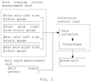
- the collection control unit comprises: a data collector, configured to collect the strain values on both sides of the axle housing of the vehicle body and the roll angle of the vehicle body; and a controller, configured to calculate a strain difference between the strain values according to the strain values on both sides of the axle housing of the vehicle body, and output a corresponding alarm control signal according to the strain difference between the strain values and the roll angle of the vehicle body.
- the alarm unit comprises a buzzer and an alarm light.
- the present disclosure also provides a rollover risk prediction method, comprising: collecting strain values on both sides of an axle housing of a vehicle body and a roll angle of the vehicle body; calculating a strain difference between the strain values according to the strain values on both sides of the axle housing of the vehicle body; and comparing the strain difference between the strain values and the roll angle of the vehicle body with corresponding thresholds respectively, and outputting a corresponding rollover risk prediction result according to a comparison result.
- the step of outputting a corresponding rollover risk prediction result according to a comparison result comprises: if
- the step of outputting a corresponding rollover risk prediction result according to a comparison result comprises: outputting a vehicle rollover risk prediction result that there is no rollover risk in the case where
- ⁇ ⁇ 1 is satisfied, and ⁇ ⁇ ⁇ 1 is satisfied; and outputting a vehicle rollover risk prediction result that there is a low rollover risk in other cases, wherein ⁇ 1 is a strain value on a left side of the front axle housing of the vehicle body, ⁇ 2 is a strain value on
- the present disclosure further provides a rollover alarming method, comprising the steps that: predicting a rollover risk using the foregoing rollover risk prediction method; not activating a warning unit if there is a rollover risk prediction result of no rollover risk; warning, by the warning unit, at a long interval and flashing a yellow warning light if there is a rollover risk prediction result of a low rollover risk, wherein the long interval is no less than 10 seconds; and warning, by the warning unit, at a short interval and flashing a red warning light if there is a rollover risk prediction result of a high rollover risk, wherein the short interval is no more than 5 seconds.
- the present disclosure provides a rollover alarming system, a rollover risk prediction method, and a rollover alarming method.
- the axle housing strain measurement unit measures strain values on both sides of the axle housing of the vehicle body
- the roll angle measurement unit measures a roll angle of the vehicle body.
- the collection control unit is configured to collect the strain values on both sides of the axle housing of the vehicle body and the roll angle of the vehicle body, calculate a strain difference between the strain values according to the strain values on both sides of the axle housing of the vehicle body, and output a corresponding alarm control signal according to the strain difference between both sides of the axle housing of the vehicle body and the roll angle of the vehicle body.
- the alarm unit is configured to output a corresponding alarm signal according to the received alarm control signal, so as to inform the driver of protection from danger of rollover and take corresponding protective measures in advance.
- the present disclosure is constituted in a simple structure and a low cost.
- first strain gauge 1-2. second strain gauge; 1-4. fourth strain gauge; 2. roll angle sensor of the vehicle body; 3. alarm buzzer; 4. collection control unit ; 5. front axle; 6. rear axle; 7-1. left front wheel; 7-2. right front wheel; 7-3. left rear wheel; 7-4. right rear wheel.
- the present disclosure provides a rollover alarm system for construction machinery, which comprises an axle housing strain measurement unit, a roll angle measurement unit, a collection control unit, and an alarm unit.
- the axle housing strain measurement unit is configured to measure strain values on both sides of the axle housing of the vehicle body
- the roll angle measurement unit is configured to measure a roll angle of the vehicle body.
- the collection control unit is configured to collect the strain values on both sides of the axle housing of the vehicle body and the roll angle of the vehicle body, calculate a strain difference between the strain values according to the strain values on both sides of the axle housing of the vehicle body, and output a corresponding alarm control signal according to the strain difference between both sides of the axle housing of the vehicle body and the roll angle of the vehicle body.
- the alarm unit is configured to output a corresponding alarm signal according to the received alarm control signal.
- the axle housing strain measurement unit comprises strain gauges fixedly mounted on both sides of the axle housing.
- the strain gauges which are adhesively fixed on the axle housing, comprise a first strain gauge 1-1, a second strain gauge 1-2, a third strain gauge, and a fourth strain gauge 1-4, which are mounted on a left side of the front axle housing, a right side of the front axle housing, a left side of the rear axle housing, and a right side of the rear axle housing respectively.
- the action forces on the left and right wheels (a left front wheel 7-1, a right front wheel 7-2, a left rear wheel 7-3, a right rear wheel 7-4) in a vertical direction vary in a way such that the action force on one side becomes larger and the action force on the other side becomes smaller.
- the variation in the action forces of the left and right wheels in a vertical direction bring about the variation in the structural stresses on both sides of the axle housing, and there is also a variation in the structural strains.
- the strain gauges mounted on both sides of the axle housing detect the stress conditions at positions where the sensors are mounted. The variation in the strain difference between both sides reflects the greatness of the overturning moment. The larger the difference between the stresses on both sides is, the greater the overturning moment will be and the greater the rollover risk will be.
- the roll angle measurement unit comprises a roll angle sensor 2 of the vehicle body fixed on a main structure of the vehicle body.
- the roll angle sensor 2 of the vehicle body is fixed at any position of the vehicle body structure, and the structure does not move relative to the vehicle body.
- the roll angle sensor 2 of the vehicle body is fixed on the axle housing of the rear axle 6.
- the greatness of the roll angle of the vehicle body reflects the included angle between the vehicle body and the horizontal plane. The greater the roll angle of the vehicle body is, the greater the roll risk will be.
- the collection control unit 4 comprises a data collector and a controller.
- the data collector is configured to collect the strain values on both sides of the axle housing of the vehicle body and the roll angle of the vehicle body
- the controller is configured to calculate a strain difference between the strain values according to the strain values on both sides of the axle housing of the vehicle body, and output a corresponding alarm control signal according to the strain difference between the strain values and the roll angle of the vehicle body.
- the present disclosure also discloses a rollover prediction method for construction machinery, which comprises the following steps:
- the above-described step of outputting a corresponding rollover risk prediction result according to a comparison result comprises:
- the strain gauge 1, the roll angle sensor 2 of the vehicle body, and the alarm buzzer 3 are connected to the collection control unit 4 through a data line.
- the step of outputting a corresponding rollover risk prediction result according to a comparison result comprises:
- the prediction method comprises the following steps:
Abstract
Description
- The present application is based on and claims priority to China Patent Application No.
CN201910902501.1 filed on September 24, 2019 - The present disclosure relates to the technical field of construction machinery, and in particular to a rollover alarming system, a rollover risk prediction method, and a rollover alarming method.
- As a modern construction device, construction machinery is widely applied in transportation, energy development, building construction, mining exploitation, agro-forestry, aqua-forestry, national defense construction and other fields. Since the construction machinery is operated in harsh working conditions and used in complex and volatile working conditions, rollover accidents are inevitable, thereby rendering great disasters to users and producing huge economic losses. Construction machinery enterprises home and abroad invested a large amount of resources in the development and design of the rollover protection structure (ROPS) of the cab, and achieved certain technical results . This is a protection mechanism after occurrence of a rollover accident, in which requirements are mainly raised for the amount of structural deformation of the cab.
- The existing anti-rollover protection technology for the cab of the construction machinery is mainly aimed at the safety protection of the cab and the driver when the construction machinery is subjected to a rollover accident. At this time, the rollover accident inevitably causes damage to the construction machinery and the cab, and the driver is also physically injured to a certain extent. The existing anti-rollover technology can only guarantee the basic secondary use of the construction machinery and the basic survival of the driver after the rollover accident, but cannot provide rollover alarming for the construction machinery so as to prevent damage to the entire vehicle and different degrees of injury to the driver.
- It is an object of the present disclosure to provide a rollover alarming system, a rollover risk prediction method and a rollover alarming method, so as to solve the above-described problems existing in the background art.
- The above-described technical object of the present disclosure is achieved by the following technical solution:
- The present disclosure provides a rollover alarming system, comprising: an axle housing strain measurement unit, configured to measure strain values on both sides of an axle housing of a vehicle body; a roll angle measurement unit, configured to measure a roll angle of the vehicle body; a collection control unit, configured to collect the strain values on both sides of the axle housing of the vehicle body and the roll angle of the vehicle body, calculate a strain difference between the strain values according to the strain values on both sides of the axle housing of the vehicle body, and output a corresponding alarm control signal according to the strain difference between both sides of the axle housing of the vehicle body and the roll angle of the vehicle body; and an alarm unit, configured to output a corresponding alarm signal according to the received alarm control signal.
- In some embodiments, the axle housing strain measurement unit comprises a first strain gauge fixed to a left side of a front axle housing of the vehicle body, a second strain gauge fixed to a right side of the front axle housing of the vehicle body, a third strain gauge fixed to a left side of a rear axle housing of the vehicle body, and a fourth strain gauge fixed to a right side of the rear axle housing of the vehicle body.
- In some embodiments, the roll angle measurement unit comprises a roll angle sensor of the vehicle body fixed on the main structure of the vehicle body.
- In some embodiments, the main structure of the vehicle body comprises a rear axle housing of the vehicle body.
- In some embodiments, the collection control unit comprises: a data collector, configured to collect the strain values on both sides of the axle housing of the vehicle body and the roll angle of the vehicle body; and a controller, configured to calculate a strain difference between the strain values according to the strain values on both sides of the axle housing of the vehicle body, and output a corresponding alarm control signal according to the strain difference between the strain values and the roll angle of the vehicle body.
- In some embodiments, the alarm unit comprises a buzzer and an alarm light.
- The present disclosure also provides a rollover risk prediction method, comprising: collecting strain values on both sides of an axle housing of a vehicle body and a roll angle of the vehicle body; calculating a strain difference between the strain values according to the strain values on both sides of the axle housing of the vehicle body; and comparing the strain difference between the strain values and the roll angle of the vehicle body with corresponding thresholds respectively, and outputting a corresponding rollover risk prediction result according to a comparison result.
- In some embodiments, the step of outputting a corresponding rollover risk prediction result according to a comparison result comprises: if | ε 2- ε 1 | <Δ1 and | ε 4 - ε 3 | < Δ 1 and α < δ 1, there is no rollover risk; if | ε 2- ε 1 | ≥ Δ 1 or | ε 4- ε 3 | ≥ Δ 1 or α ≥ δ 1, there is a low rollover risk; if | ε 2- ε 1 | ≥ Δ 2 or | ε 4- ε 3 | ≥ Δ 2 or α ≥ δ 2 or | ε 2- ε 1 | ≥ Δ 1 or | ε 4 - ε 3 | ≥ Δ 1 and α ≥ δ 1, there is a high rollover risk, in the formulas: Δ 1 is 10% to 20% of an average strain on the axle housing, that is, 10% to 20% of ( ε 1+ ε 2+ ε 3+ ε 4) /4, Δ 2 is 20% to 30% of the average strain on the axle housing, that is, 20% to 30% of (ε1+ε2+ε3+ε4) /4, δ1 is 10% to 20% of an included angle between a horizontal plane and a line connecting a vehicle body mass center and a vehicle wheel, and δ2 is 20% to 40% of the included angle between the horizontal plane and the line connecting the vehicle body mass center and the vehicle wheel, α is the roll angle of the vehicle body, ε1 is a strain value on a left side of a front axle housing, ε2 is a strain value on a right side of the front axle housing, ε3 is a strain value on a left side of a rear axle housing, and ε4 is a strain value on a right side of the rear axle housing.
- In some embodiments, the step of outputting a corresponding rollover risk prediction result according to a comparison result comprises: outputting a vehicle rollover risk prediction result that there is no rollover risk in the case where | ε2 - ε1 < Δ1 and | ε4-ε3 | < Δ1 and α<δ1; outputting a vehicle rollover risk prediction result that there is a high rollover risk in the case where at least one of | ε 2- ε 1 | ≥ Δ 2 or | ε 4- ε 3 | ≥ Δ 2 or α ≥ δ2 is satisfied, or in the case where at least one of | ε 2- ε 1 | ≥ Δ 1 or | ε 4- ε 3 | ≥ Δ 1 is satisfied, and α ≥ δ 1 is satisfied; and outputting a vehicle rollover risk prediction result that there is a low rollover risk in other cases, wherein ε1 is a strain value on a left side of the front axle housing of the vehicle body, ε2 is a strain value on a right side of a front axle housing of the vehicle body, ε3 is a strain value on a left side of a rear axle housing of the vehicle body, ε4 is a strain value on a right side of the rear axle housing of the vehicle body, Δ1=(ε1+ε2+ε3+ε4) × k1/4, k1 has a value range of [0.1,0.2], Δ2=(ε1+ε2+ε3+ε4) ×k2/4, k2 has a value range of [0.2, 0.3], δ1=θ×k3, θ is an included angle between a horizontal plane and a plane determined by a vehicle body mass center and a vehicle wheel, k3 has a value range of [0.1,0.2], δ2=θ×k4, k4 has a value range of [0.2, 0.4], and α is a roll angle of the vehicle body.
- The present disclosure further provides a rollover alarming method, comprising the steps that: predicting a rollover risk using the foregoing rollover risk prediction method; not activating a warning unit if there is a rollover risk prediction result of no rollover risk; warning, by the warning unit, at a long interval and flashing a yellow warning light if there is a rollover risk prediction result of a low rollover risk, wherein the long interval is no less than 10 seconds; and warning, by the warning unit, at a short interval and flashing a red warning light if there is a rollover risk prediction result of a high rollover risk, wherein the short interval is no more than 5 seconds.
- The beneficial effects of the present disclosure are as follows:
- The present disclosure provides a rollover alarming system, a rollover risk prediction method, and a rollover alarming method. The axle housing strain measurement unit measures strain values on both sides of the axle housing of the vehicle body, and the roll angle measurement unit measures a roll angle of the vehicle body. The collection control unit is configured to collect the strain values on both sides of the axle housing of the vehicle body and the roll angle of the vehicle body, calculate a strain difference between the strain values according to the strain values on both sides of the axle housing of the vehicle body, and output a corresponding alarm control signal according to the strain difference between both sides of the axle housing of the vehicle body and the roll angle of the vehicle body. The alarm unit is configured to output a corresponding alarm signal according to the received alarm control signal, so as to inform the driver of protection from danger of rollover and take corresponding protective measures in advance. At the same time, the present disclosure is constituted in a simple structure and a low cost.
-
-
Fig. 1 is a schematic view of a mounting structure of the rollover alarming system provided according to embodiments of the present disclosure; -
Fig. 2 is a structural block view of the rollover alarming system provided according to embodiments of the present disclosure; -
Fig. 3 is a flowchart of the rollover alarming method provided according to embodiments of the present disclosure. - In the accompanying drawings: 1-1. first strain gauge; 1-2. second strain gauge; 1-4. fourth strain gauge; 2. roll angle sensor of the vehicle body; 3. alarm buzzer; 4. collection control unit ; 5. front axle; 6. rear axle; 7-1. left front wheel; 7-2. right front wheel; 7-3. left rear wheel; 7-4. right rear wheel.
- The present disclosure will be further described in detail below in conjunction with the accompanying drawings.
- It should be noted that, all directional indications (such as up, down, left, right, front, back...) in the embodiments of the present disclosure are only intended to explain the relative positional relationships, movement conditions and the like among various components in a specific attitude (as shown in the accompanying drawings). If this particular attitude varies, the directional indications also vary along the same accordingly. In addition, the terms "mounted", "provided", "having", "connecting", "connected", and "socketed" should be understood in a broad sense. For example, it may be a fixed connection, a detachable connection, or an integral construction; it may be a mechanical connection or an electrical connection; it may be directly connected, or indirectly connected through an intermediate medium, or communication between two devices, elements, or constituent parts. For those of ordinary skill in the art, the specific meanings of the above-described terms in the present application may be understood according to specific circumstances.
- As shown in
Figs. 1 ,2 , and3 , the present disclosure provides a rollover alarm system for construction machinery, which comprises an axle housing strain measurement unit, a roll angle measurement unit, a collection control unit, and an alarm unit. The axle housing strain measurement unit is configured to measure strain values on both sides of the axle housing of the vehicle body, and the roll angle measurement unit is configured to measure a roll angle of the vehicle body. The collection control unit is configured to collect the strain values on both sides of the axle housing of the vehicle body and the roll angle of the vehicle body, calculate a strain difference between the strain values according to the strain values on both sides of the axle housing of the vehicle body, and output a corresponding alarm control signal according to the strain difference between both sides of the axle housing of the vehicle body and the roll angle of the vehicle body. The alarm unit is configured to output a corresponding alarm signal according to the received alarm control signal. - The axle housing strain measurement unit comprises strain gauges fixedly mounted on both sides of the axle housing. The strain gauges which are adhesively fixed on the axle housing, comprise a first strain gauge 1-1, a second strain gauge 1-2, a third strain gauge, and a fourth strain gauge 1-4, which are mounted on a left side of the front axle housing, a right side of the front axle housing, a left side of the rear axle housing, and a right side of the rear axle housing respectively. When the vehicle body is subjected to an overturning moment, the action forces on the left and right wheels (a left front wheel 7-1, a right front wheel 7-2, a left rear wheel 7-3, a right rear wheel 7-4) in a vertical direction vary in a way such that the action force on one side becomes larger and the action force on the other side becomes smaller. The variation in the action forces of the left and right wheels in a vertical direction bring about the variation in the structural stresses on both sides of the axle housing, and there is also a variation in the structural strains. The strain gauges mounted on both sides of the axle housing detect the stress conditions at positions where the sensors are mounted. The variation in the strain difference between both sides reflects the greatness of the overturning moment. The larger the difference between the stresses on both sides is, the greater the overturning moment will be and the greater the rollover risk will be.
- The roll angle measurement unit comprises a roll angle sensor 2 of the vehicle body fixed on a main structure of the vehicle body. The roll angle sensor 2 of the vehicle body is fixed at any position of the vehicle body structure, and the structure does not move relative to the vehicle body. In this embodiment, the roll angle sensor 2 of the vehicle body is fixed on the axle housing of the rear axle 6. The greatness of the roll angle of the vehicle body reflects the included angle between the vehicle body and the horizontal plane. The greater the roll angle of the vehicle body is, the greater the roll risk will be.
- As shown in
Fig. 2 , the collection control unit 4 comprises a data collector and a controller. The data collector is configured to collect the strain values on both sides of the axle housing of the vehicle body and the roll angle of the vehicle body, and the controller is configured to calculate a strain difference between the strain values according to the strain values on both sides of the axle housing of the vehicle body, and output a corresponding alarm control signal according to the strain difference between the strain values and the roll angle of the vehicle body. - The present disclosure also discloses a rollover prediction method for construction machinery, which comprises the following steps:
- Collecting strain values on both sides of an axle housing of a vehicle body and a roll angle of the vehicle body;
- Calculating a strain difference the strain values according to the strain values on both sides of the axle housing of the vehicle body; and
- Comparing the strain difference between the strain values and the roll angle of the vehicle body with corresponding thresholds respectively, and outputting a corresponding rollover risk prediction result according to a comparison result.
- In some embodiments, the above-described step of outputting a corresponding rollover risk prediction result according to a comparison result comprises:
- When | ε 2- ε 1 | < Δ 1 and | ε 4 - ε 3 | < Δ 1 and α < δ 1, there is no rollover risk;
- When | ε 2 - ε 1 | ≥ Δ 1 or | ε 4 - ε 3 | ≥ Δ 1 or α ≥ δ 1, there is a low rollover risk;
- When | ε 2-ε 1 | ≥ Δ 2 or | ε 4 - ε 3| ≥ Δ2 or α ≥ δ 2 or | ε 2 - ε 1 | ≥ Δ 1 or | ε 4 - ε 3 | ≥ Δ 1 and α ≥ δ 1, there is a high rollover risk,
- In the formulas: Δ1 is 10% to 20% of an average strain on the axle housing, that is, 10% to 20% of (ε1+ε2+ε3+ε4)/4, Δ2 is 20% to 30% of the average strain on the axle housing, that is, 20% to 30% of (ε1+ε2+ε3+ε4)/4, δ1 is 10% to 20% of an included angle between a horizontal plane and a line connecting a vehicle body mass center and a vehicle wheel, and δ2 is 20% to 40% of the included angle between the horizontal plane and the line connecting the vehicle body mass center and the vehicle wheel, α is the roll angle of the vehicle body, ε1 is a strain value on a left side of a front axle housing, ε2 is a strain value on a right side of the front axle housing, ε3 is a strain value on a left side of a rear axle housing, and ε4 is a strain value on a right side of the rear axle housing.
- In some embodiments, the strain gauge 1, the roll angle sensor 2 of the vehicle body, and the alarm buzzer 3 are connected to the collection control unit 4 through a data line.
- In some embodiments, the step of outputting a corresponding rollover risk prediction result according to a comparison result comprises:
- Outputting a vehicle rollover risk prediction result that there is no rollover risk in the case where | ε2-ε1 | < Δ1 and | ε4-ε3 | < Δ1 and α<δ1;
- Outputting a vehicle rollover risk prediction result that there is a high rollover risk in the case where at least one of | ε 2- ε 1 | ≥ Δ 2 or | ε 4 - ε 3 | ≥ Δ 2 or α ≥ δ 2 is satisfied, or in the case where at least one of | ε 2- ε 1 | ≥Δ 1 or | ε 4- ε 3 | ≥ Δ 1 is satisfied, and α ≥ δ 1 is satisfied; and
- Outputting a rollover risk prediction result that there is a low rollover risk in other cases,
- Wherein ε1 is a strain value on a left side of a front axle housing of the vehicle body, ε2 is a strain value on a right side of the front axle housing of the vehicle body, ε3 is a strain value on a left side of a rear axle housing of the vehicle body, ε4 is a strain value on a right side of the rear axle housing of the vehicle body, Δ1 = (ε1+ε2+ε3+ε4) × k1/4, k1 has a value range of [0.1,0.2], Δ2 = (ε1+ε2+ε3+ε4)×k2/4, k2 has a value range of [0.2, 0.3], δ1=θ×k3, θ is an included angle between a horizontal plane and a plane determined by a vehicle body mass center and a vehicle wheel, k3 has a value range of [0.1,0.2], δ2=θ×k4, k4 has a value range of [0.2, 0.4], and α is a roll angle of the vehicle body.
- As shown in
Fig. 3 , the present disclosure also discloses a rollover alarming method. The prediction method comprises the following steps: - Predicting a rollover risk using the above-described rollover risk prediction method;
- Not activating a warning unit if there is a rollover risk prediction result of no rollover risk;
- Warning, by the warning unit, at a long interval and flashing a yellow warning light if there is a rollover risk prediction result of a low rollover risk, wherein the long interval is no less than 1 seconds; and
- Warning, by the warning unit, at a short interval and flashing a red warning light if there is a rollover risk prediction result of a high rollover risk, wherein the short interval is no more than 0.5 seconds.
- The preferred implementations of the present disclosure have been described in detail above. Of course, the present disclosure may also adopt different forms from the above-described embodiments. Those skilled in the art may make equivalent variations or corresponding modifications without departing from the spirit of the present disclosure, which shall fall within the protection scope of the present disclosure.
Claims (10)
- A rollover alarming system, comprising:an axle housing strain measurement unit, configured to measure strain values on both sides of an axle housing of a vehicle body;a roll angle measurement unit, configured to measure a roll angle of the vehicle body;a collection control unit, configured tocollect the strain values on both sides of the axle housing of the vehicle body and the roll angle of the vehicle body,calculate a strain difference between the strain values according to the strain values on both sides of the axle housing of the vehicle body, andoutput a corresponding alarm control signal according to the strain difference between both sides of the axle housing of the vehicle body and the roll angle of the vehicle body; andan alarm unit, configured to output a corresponding alarm signal according to the received alarm control signal.
- The rollover alarming system according to claim 1, wherein the axle housing strain measurement unit comprises a first strain gauge fixed to a left side of a front axle housing of the vehicle body, a second strain gauge fixed to a right side of the front axle housing of the vehicle body, a third strain gauge fixed to a left side of a rear axle housing of the vehicle body, and a fourth strain gauge fixed to a right side of the rear axle housing of the vehicle body.
- The rollover alarming system according to claim 1, wherein the roll angle measurement unit comprises a roll angle sensor of the vehicle body fixed on the main structure of the vehicle body.
- The rollover alarming system of claim 3, wherein the main structure of the vehicle body comprises a rear axle housing of the vehicle body.
- The rollover alarming system according to claim 1, wherein the collection control unit comprises:a data collector, configured to collect the strain values on both sides of the axle housing of the vehicle body and the roll angle of the vehicle body; anda controller, configured to calculate a strain difference between the strain values according to the strain values on both sides of the axle housing of the vehicle body, and output a corresponding alarm control signal according to the strain difference between the strain values and the roll angle of the vehicle body.
- The rollover alarming system according to claim 1, wherein the alarm unit comprises a buzzer and an alarm light.
- A rollover risk prediction method, comprising:collecting strain values on both sides of an axle housing of a vehicle body and a roll angle of the vehicle body;calculating a strain difference between the strain values according to the strain values on both sides of the axle housing of the vehicle body; andcomparing the strain difference between the strain values and the roll angle of the vehicle body with corresponding thresholds respectively, and outputting a corresponding rollover risk prediction result according to a comparison result.
- The rollover risk prediction method according to claim 7, wherein the outputting a corresponding rollover risk prediction result according to a comparison result comprises:if | ε2 - ε1 | < Δ1 and | ε4-ε3 | < Δ1 and α<δ1, there is no rollover risk;if |ε2-ε1|≥Δ1 or |ε4-ε3|≥Δ1 or α≥δ1, there is a low rollover risk;if | ε2 - ε1 | ≥Δ2 or | ε4-ε3 | ≥Δ2 or α≥δ2 or | ε2 - ε1 | ≥Δ1 or | ε4-ε3 | ≥Δ1 and α≥δ1, there is a high rollover risk,in the formulas: Δ1 is 10% to 20% of an average strain on the axle housing, that is, 10% to 20% of (ε1+ε2+ε3+ε4)/4; Δ2 is 20% to 30% of the average strain on the axle housing, that is, 20% to 30% of (ε1+ε2+ε3+ε4) /4, δ1 is 10% to 20% of an included angle between a horizontal plane and a line connecting a vehicle body mass center and a vehicle wheel, and δ2 is 20% to 40% of the included angle between the horizontal plane and the line connecting the vehicle body mass center and the vehicle wheel , α is the roll angle of the vehicle body, ε1 is a strain value on a left side of a front axle housing, ε2 is a strain value on a right side of the front axle housing, ε3 is a strain value on a left side of a rear axle housing, and ε4 is a strain value on a right side of the rear axle housing.
- The rollover risk prediction method according to claim 7, wherein the outputting a corresponding rollover risk prediction result according to a comparison result comprises:outputting a vehicle rollover risk prediction result that there is no rollover risk in the case where |ε2-ε1|<Δ1 and |ε4-ε3|<Δ1 and α<δ1;outputting a vehicle rollover risk prediction result that there is a high rollover risk in the case where at least one of | ε2 - ε1 1≥Δ2 or | ε4-ε3 |≥Δ2 or α≥δ2 is satisfied, or in the case where at least one of | ε2-ε1 |≥Δ1 or | ε4-ε3 | ≥Δ1 is satisfied, and α≥δ1 is satisfied; andoutputting a rollover risk prediction result that there is a low rollover risk in other cases,wherein ε1 is a strain value on a left side of a front axle housing of the vehicle body, ε2 is a strain value on a right side of the front axle housing of the vehicle body, ε3 is a strain value on a left side of a rear axle housing of the vehicle body, ε4 is a strain value on a right side of the rear axle housing of the vehicle body, Δ1= (ε1+ε2+ε3+ε4) × k1/4, k1 has a value range of [0.1,0.2], Δ2=(ε1+ε2+ε3+ε4)×k2/4, k2 has a value range of [0.2, 0.3], δ1=θ×k3, θ is an included angle between a horizontal plane and a plane determined by a vehicle body mass center and a vehicle wheel, k3 has a value range of [0.1, 0.2] , δ2=θ×k4, k4 has a value range of [0.2, 0.4], and α is the roll angle of the vehicle body.
- A rollover alarming method, comprising:predicting a rollover risk using the rollover risk prediction method according to claim 7 or 8;not activating a warning unit if there is a rollover risk prediction result of no rollover risk;warning, by the warning unit, at a long interval and flashing a yellow warning light if there is a rollover risk prediction result of a low rollover risk, wherein the long interval is no less than 10 seconds; andwarning, by the warning unit, at a short interval and flashing a red warning light if there is a rollover risk prediction result of a high rollover risk, wherein the short interval is no more than 5 seconds.
Applications Claiming Priority (2)
| Application Number | Priority Date | Filing Date | Title |
|---|---|---|---|
| CN201910902501.1A CN110667568B (en) | 2019-09-24 | 2019-09-24 | Rollover alarm system, rollover risk prediction method and rollover alarm method |
| PCT/CN2020/094012 WO2020211882A1 (en) | 2019-09-24 | 2020-06-02 | Vehicle rollover warning system, vehicle rollover risk prediction method, and vehicle rollover warning method |
Publications (2)
| Publication Number | Publication Date |
|---|---|
| EP3912876A1 true EP3912876A1 (en) | 2021-11-24 |
| EP3912876A4 EP3912876A4 (en) | 2022-11-16 |
Family
ID=69077286
Family Applications (1)
| Application Number | Title | Priority Date | Filing Date |
|---|---|---|---|
| EP20792023.2A Pending EP3912876A4 (en) | 2019-09-24 | 2020-06-02 | Vehicle rollover warning system, vehicle rollover risk prediction method, and vehicle rollover warning method |
Country Status (4)
| Country | Link |
|---|---|
| US (1) | US11816939B2 (en) |
| EP (1) | EP3912876A4 (en) |
| CN (1) | CN110667568B (en) |
| WO (1) | WO2020211882A1 (en) |
Cited By (1)
| Publication number | Priority date | Publication date | Assignee | Title |
|---|---|---|---|---|
| CN114291074A (en) * | 2021-12-02 | 2022-04-08 | 江铃汽车股份有限公司 | Vehicle rollover early warning method and device and storage medium |
Families Citing this family (2)
| Publication number | Priority date | Publication date | Assignee | Title |
|---|---|---|---|---|
| CN110667568B (en) * | 2019-09-24 | 2021-11-30 | 江苏徐工工程机械研究院有限公司 | Rollover alarm system, rollover risk prediction method and rollover alarm method |
| CN112874413A (en) * | 2021-01-26 | 2021-06-01 | 浙江双友物流器械股份有限公司 | Transport cargo rollover early warning method based on matrix type pressure sensor |
Family Cites Families (23)
| Publication number | Priority date | Publication date | Assignee | Title |
|---|---|---|---|---|
| US5610575A (en) | 1994-08-25 | 1997-03-11 | Automotive Systems Laboratory, Inc. | Method and system for detecting vehicle roll-over |
| US5825284A (en) * | 1996-12-10 | 1998-10-20 | Rollover Operations, Llc | System and method for the detection of vehicle rollover conditions |
| EP1585940A4 (en) * | 2002-03-19 | 2009-09-02 | Automotive Systems Lab | Vehicle rollover detection system |
| JP4811089B2 (en) * | 2006-02-02 | 2011-11-09 | いすゞ自動車株式会社 | Vehicle rollover risk determination device |
| US20090164060A1 (en) | 2007-02-19 | 2009-06-25 | Solidica, Inc. | Vehicle instability detection and prevention system |
| US7573375B2 (en) | 2007-05-02 | 2009-08-11 | Paccar Inc | Rollover prediction and warning method |
| US8010252B2 (en) | 2007-10-05 | 2011-08-30 | Ford Global Technologies | Trailer oscillation detection and compensation method for a vehicle and trailer combination |
| JP5113098B2 (en) | 2009-01-23 | 2013-01-09 | 日立オートモティブシステムズ株式会社 | Vehicle rollover prevention control device and vehicle rollover prevention control method |
| CN102756686B (en) * | 2011-04-26 | 2015-07-29 | 贵州大学 | The method and apparatus of early warning vehicle rollover |
| US8902055B2 (en) * | 2011-06-08 | 2014-12-02 | Msi Defense Solutions, Llc | Rollover warning system for a vehicle |
| US8983722B2 (en) | 2011-12-12 | 2015-03-17 | GM Global Technology Operations LLC | System and method for vehicle rollover prediction |
| WO2013172136A1 (en) | 2012-05-16 | 2013-11-21 | 楽天株式会社 | Point system, method for controlling point system, point management device, program, and information storage medium |
| CN203391769U (en) | 2013-07-02 | 2014-01-15 | 徐州徐工施维英机械有限公司 | Tipping preventing device and concrete mixing truck |
| WO2015063309A1 (en) * | 2013-11-03 | 2015-05-07 | Desarrollo Tecnológico Agroindustrial | Dynamic rollover protection system |
| EP3072846A1 (en) | 2015-03-25 | 2016-09-28 | DANA ITALIA S.p.A | System and method for detecting an impending tip over of a vehicle |
| EP3303084B1 (en) | 2015-06-03 | 2023-07-26 | Volvo Construction Equipment AB | A method and system for predicting a risk for rollover of a working machine |
| CN104865079B (en) | 2015-06-14 | 2018-04-13 | 山东交通学院 | A kind of automobile roll comprehensive evaluation index measuring device and its computational methods |
| CN204679143U (en) * | 2015-06-26 | 2015-09-30 | 秦皇岛科云工贸有限责任公司 | Strain transducer level measuring and controlling device |
| CN205417165U (en) * | 2016-03-02 | 2016-08-03 | 十堰焕金工贸有限公司 | Electric automobile driving axle assembly |
| CN106945659B (en) | 2017-03-24 | 2023-04-25 | 南京航空航天大学 | Automobile rollover prevention early warning device and method based on tire cornering deformation |
| CN108099919B (en) | 2017-11-09 | 2019-01-29 | 珠海格力电器股份有限公司 | Preventing vehicle rollover method for early warning, device, storage medium and vehicle |
| DE102018207385A1 (en) | 2018-05-14 | 2019-11-14 | Continental Automotive Gmbh | Method for determining a probability of tipping a vehicle, evaluation unit, system and vehicle |
| CN110667568B (en) | 2019-09-24 | 2021-11-30 | 江苏徐工工程机械研究院有限公司 | Rollover alarm system, rollover risk prediction method and rollover alarm method |
-
2019
- 2019-09-24 CN CN201910902501.1A patent/CN110667568B/en active Active
-
2020
- 2020-06-02 WO PCT/CN2020/094012 patent/WO2020211882A1/en unknown
- 2020-06-02 EP EP20792023.2A patent/EP3912876A4/en active Pending
- 2020-06-02 US US17/278,768 patent/US11816939B2/en active Active
Cited By (2)
| Publication number | Priority date | Publication date | Assignee | Title |
|---|---|---|---|---|
| CN114291074A (en) * | 2021-12-02 | 2022-04-08 | 江铃汽车股份有限公司 | Vehicle rollover early warning method and device and storage medium |
| CN114291074B (en) * | 2021-12-02 | 2023-10-17 | 江铃汽车股份有限公司 | Vehicle rollover early warning method, device and storage medium |
Also Published As
| Publication number | Publication date |
|---|---|
| US11816939B2 (en) | 2023-11-14 |
| US20220036671A1 (en) | 2022-02-03 |
| CN110667568B (en) | 2021-11-30 |
| WO2020211882A1 (en) | 2020-10-22 |
| CN110667568A (en) | 2020-01-10 |
| EP3912876A4 (en) | 2022-11-16 |
Similar Documents
| Publication | Publication Date | Title |
|---|---|---|
| EP3912876A1 (en) | Vehicle rollover warning system, vehicle rollover risk prediction method, and vehicle rollover warning method | |
| CN102219158B (en) | Method and device for preventing collision in tower crane cluster operation | |
| CN201473235U (en) | Stereoscopic visual security alarming system used for tower crane | |
| CN201619998U (en) | Folding-arm anti-rollover device of working platform of aerial working truck device | |
| CN204405242U (en) | A kind of belt wheel side-compression cable tension real-time detection apparatus | |
| CN102344093A (en) | Tower crane anti-leaning intelligent monitoring system | |
| CN103017724A (en) | Method for diagnosing sound condition of steel structure and steel structure inclination angle diagnosing device | |
| CN202357808U (en) | Hydraulic flat tire deviation preventive device for automobile | |
| CN201762063U (en) | Forklift rollover-protection sensing and early-warning device and forklift utilizing same | |
| CN201856724U (en) | Intelligent vehicle protecting device | |
| CN102351132B (en) | Gravity center and grounding pressure display device and method for crawler crane | |
| CN201442834U (en) | Overloading detection device of working platform | |
| CN203021204U (en) | Upper and lower layer anti-collision device for crane | |
| CN104691473A (en) | ARM-based vehicle-mounted pedestrian detection warning system | |
| CN202296926U (en) | Intelligent inclination-preventing monitoring system for tower crane | |
| CN209776453U (en) | Derailing alarm device for mining electric locomotive | |
| CN212153193U (en) | Town road limit for height device | |
| CN211107113U (en) | Intelligent mining wide-body vehicle | |
| CN203806995U (en) | Anti-collision control system for cranes | |
| CN111207264A (en) | High-precision pipeline leak detection positioning alarm device | |
| CN202938818U (en) | On-line monitoring system of inclination of intelligent power grid transmission line poles and towers | |
| CN107235007A (en) | A kind of lorry overload protective device | |
| CN105644370A (en) | Anti-rollover system for electro-tricycle | |
| EP3187397B1 (en) | Automatic alignment system with warning light | |
| CN219467734U (en) | Intelligent obstacle-avoiding electric locomotive based on 3D infrared thermal imaging |
Legal Events
| Date | Code | Title | Description |
|---|---|---|---|
| STAA | Information on the status of an ep patent application or granted ep patent |
Free format text: STATUS: THE INTERNATIONAL PUBLICATION HAS BEEN MADE |
|
| STAA | Information on the status of an ep patent application or granted ep patent |
Free format text: STATUS: THE INTERNATIONAL PUBLICATION HAS BEEN MADE |
|
| PUAI | Public reference made under article 153(3) epc to a published international application that has entered the european phase |
Free format text: ORIGINAL CODE: 0009012 |
|
| STAA | Information on the status of an ep patent application or granted ep patent |
Free format text: STATUS: REQUEST FOR EXAMINATION WAS MADE |
|
| 17P | Request for examination filed |
Effective date: 20210120 |
|
| AK | Designated contracting states |
Kind code of ref document: A1 Designated state(s): AL AT BE BG CH CY CZ DE DK EE ES FI FR GB GR HR HU IE IS IT LI LT LU LV MC MK MT NL NO PL PT RO RS SE SI SK SM TR |
|
| A4 | Supplementary search report drawn up and despatched |
Effective date: 20221018 |
|
| RIC1 | Information provided on ipc code assigned before grant |
Ipc: B60W 30/04 20060101AFI20221012BHEP |
|
| DAV | Request for validation of the european patent (deleted) | ||
| DAX | Request for extension of the european patent (deleted) |