EP3912791A1 - Mold for molding base material integrated gasket - Google Patents
Mold for molding base material integrated gasket Download PDFInfo
- Publication number
- EP3912791A1 EP3912791A1 EP19910618.8A EP19910618A EP3912791A1 EP 3912791 A1 EP3912791 A1 EP 3912791A1 EP 19910618 A EP19910618 A EP 19910618A EP 3912791 A1 EP3912791 A1 EP 3912791A1
- Authority
- EP
- European Patent Office
- Prior art keywords
- mold
- base material
- gasket
- isolated
- isolated rubber
- Prior art date
- Legal status (The legal status is an assumption and is not a legal conclusion. Google has not performed a legal analysis and makes no representation as to the accuracy of the status listed.)
- Granted
Links
Images

Classifications
-
- B—PERFORMING OPERATIONS; TRANSPORTING
- B29—WORKING OF PLASTICS; WORKING OF SUBSTANCES IN A PLASTIC STATE IN GENERAL
- B29C—SHAPING OR JOINING OF PLASTICS; SHAPING OF MATERIAL IN A PLASTIC STATE, NOT OTHERWISE PROVIDED FOR; AFTER-TREATMENT OF THE SHAPED PRODUCTS, e.g. REPAIRING
- B29C45/00—Injection moulding, i.e. forcing the required volume of moulding material through a nozzle into a closed mould; Apparatus therefor
- B29C45/14—Injection moulding, i.e. forcing the required volume of moulding material through a nozzle into a closed mould; Apparatus therefor incorporating preformed parts or layers, e.g. injection moulding around inserts or for coating articles
- B29C45/14336—Coating a portion of the article, e.g. the edge of the article
- B29C45/14418—Sealing means between mould and article
-
- B—PERFORMING OPERATIONS; TRANSPORTING
- B29—WORKING OF PLASTICS; WORKING OF SUBSTANCES IN A PLASTIC STATE IN GENERAL
- B29C—SHAPING OR JOINING OF PLASTICS; SHAPING OF MATERIAL IN A PLASTIC STATE, NOT OTHERWISE PROVIDED FOR; AFTER-TREATMENT OF THE SHAPED PRODUCTS, e.g. REPAIRING
- B29C45/00—Injection moulding, i.e. forcing the required volume of moulding material through a nozzle into a closed mould; Apparatus therefor
- B29C45/14—Injection moulding, i.e. forcing the required volume of moulding material through a nozzle into a closed mould; Apparatus therefor incorporating preformed parts or layers, e.g. injection moulding around inserts or for coating articles
- B29C45/14336—Coating a portion of the article, e.g. the edge of the article
-
- B—PERFORMING OPERATIONS; TRANSPORTING
- B29—WORKING OF PLASTICS; WORKING OF SUBSTANCES IN A PLASTIC STATE IN GENERAL
- B29C—SHAPING OR JOINING OF PLASTICS; SHAPING OF MATERIAL IN A PLASTIC STATE, NOT OTHERWISE PROVIDED FOR; AFTER-TREATMENT OF THE SHAPED PRODUCTS, e.g. REPAIRING
- B29C45/00—Injection moulding, i.e. forcing the required volume of moulding material through a nozzle into a closed mould; Apparatus therefor
- B29C45/14—Injection moulding, i.e. forcing the required volume of moulding material through a nozzle into a closed mould; Apparatus therefor incorporating preformed parts or layers, e.g. injection moulding around inserts or for coating articles
- B29C45/14336—Coating a portion of the article, e.g. the edge of the article
- B29C2045/14459—Coating a portion of the article, e.g. the edge of the article injecting seal elements
-
- B—PERFORMING OPERATIONS; TRANSPORTING
- B29—WORKING OF PLASTICS; WORKING OF SUBSTANCES IN A PLASTIC STATE IN GENERAL
- B29L—INDEXING SCHEME ASSOCIATED WITH SUBCLASS B29C, RELATING TO PARTICULAR ARTICLES
- B29L2031/00—Other particular articles
- B29L2031/34—Electrical apparatus, e.g. sparking plugs or parts thereof
- B29L2031/3468—Batteries, accumulators or fuel cells
-
- Y—GENERAL TAGGING OF NEW TECHNOLOGICAL DEVELOPMENTS; GENERAL TAGGING OF CROSS-SECTIONAL TECHNOLOGIES SPANNING OVER SEVERAL SECTIONS OF THE IPC; TECHNICAL SUBJECTS COVERED BY FORMER USPC CROSS-REFERENCE ART COLLECTIONS [XRACs] AND DIGESTS
- Y02—TECHNOLOGIES OR APPLICATIONS FOR MITIGATION OR ADAPTATION AGAINST CLIMATE CHANGE
- Y02E—REDUCTION OF GREENHOUSE GAS [GHG] EMISSIONS, RELATED TO ENERGY GENERATION, TRANSMISSION OR DISTRIBUTION
- Y02E60/00—Enabling technologies; Technologies with a potential or indirect contribution to GHG emissions mitigation
- Y02E60/30—Hydrogen technology
- Y02E60/50—Fuel cells
Definitions
- the present disclosure relates to a mold to be used to mold a base-material/gasket unit.
- a base-material/gasket unit to be arranged in a fuel cell as one of its components is integrally constructed of a base material which is formed of a resin film, a gasket main body which is formed on a surface of the base material by injection molding, and isolated rubber portions which are formed on the surface of the base material by injection molding (see Japanese Patent Laid-Open Publication No. 2002-231274 , for example).
- the isolated rubber portions guide flows of a fluid such as fuel gas or cooling water to facilitate smooth flows from a manifold portion to a fuel cell reaction portion and from the fuel cell reaction portion to the manifold portion.
- a fluid such as fuel gas or cooling water
- the base-material/gasket unit is formed by inserting the base material of a resin film as an insert by using an injection mold.
- the base material may partially be deformed, more specifically bulge toward the isolated rubber portions to a large extent.
- the isolated rubber portions may be formed on the surface of the deformed base material. Such deformation may cause molding failure to be eliminated.
- a base-material/gasket unit mold according to the present disclosure includes
- a base-material/gasket unit mold according to an embodiment is used to form a base-material/gasket unit 101 shown in Figs. 1 and 2 .
- the base-material/gasket unit 101 includes a base material 111, a gasket main body 121, and isolated rubber portions 131.
- the gasket main body 121 and the isolated rubber portions 131 are formed on a surface of the base material 111 by injection molding.
- the base-material/gasket unit 101 is integrally constructed of the base material 111, the gasket main body 121, and the isolated rubber portions 131.
- the base material 111 is formed of a resin film.
- the gasket main body 121 is formed on the surface of the base material 111 by injection molding.
- the isolated rubber portions 131 are formed on the surface of the base material 111 by injection molding.
- the base material 111 is formed of a resin film having a flat rectangular shape.
- the base material 111 has a hollow portion (cut-out portion) 112 in the central part of the surface.
- a fuel cell reaction portion will be arranged in the hollow portion 112 when cells are assembled.
- the base material 111 has hollow portions (cut-out portions) 113 in the four corner parts of the surface.
- the hollow portions 113 will serve parts of manifold paths when cells are assembled.
- Exemplary materials of the resin film can be provided by PEN (polyethylene naphthalate), PP (polypropylene), PPSU (polyphenylsulfone), PA (polyamide), and SPS (syndiotactic polystyrene).
- the gasket main body 121 includes an exterior-side gasket main portion 122 and interior-side gasket main portions 123.
- the exterior-side gasket main portion 122 has a rectangular frame shape.
- the exterior-side gasket main portion 122 surrounds the fuel cell reaction portion (hollow portion 112) to prevent leakage of a fluid such as fuel gas or cooling water which is supplied to the fuel cell reaction portion in operation of the fuel cell from the cell.
- the interior-side gasket main portions 123 separate the fuel cell reaction portion (hollow portion 112) from the manifold paths (hollow portions 113).
- the interior-side gasket main portions 123 have a notched opening 124.
- the isolated rubber portions 131 serve as a guide or rectifier which facilitates smooth flows of a fluid such as fuel gas or cooling water from the hollow portion 113 to the hollow portion 112 and from the hollow portion 112 to the hollow portion 113 through the openings 124.
- a plurality e.g., four
- the isolated rubber portions 131 are positioned on the hollow portion 112 side relative to the opening 124.
- Groove-shaped flow passages 132 are formed between the isolated rubber portions 131 adjacent to each other.
- the flow passages 132 are aligned on lines which extend from notches of the opening 124.
- the fluid such as fuel gas can smoothly flow from the hollow portion 113 through the opening 124 and the flow passages 132 into the hollow portion 112. Also, the fluid can smoothly flow from the hollow portion 112 through the flow passages 124 and the opening 132 into the hollow portion 113.
- Exemplary rubber materials which form the gasket main body 121 and the isolated rubber portions 131 can be provided by VMQ (vinylmethyl silicone rubber), EPDM (ethylene propylene rubber), and PIB (polyisobutylene). Also, adhesive rubber materials may be used to form the gasket main body 121 and the isolated rubber portions 131.
- VMQ vinylmethyl silicone rubber
- EPDM ethylene propylene rubber
- PIB polyisobutylene
- adhesive rubber materials may be used to form the gasket main body 121 and the isolated rubber portions 131.
- the base-material/gasket unit 101 is formed by inserting the base material 111 of a resin film as an insert by using an injection mold.
- an injection mold 1 includes a first half mold 11 and a second half mold 21.
- the first half mold 11 and the second half mold 21 are paired with each other, and used together to close and open the mold of first and second half molds.
- a base material holding portion 12 is arranged on a parting surface of the first half mold 11 (first parting surface).
- the base material holding portion 12 holds the base material 111 as an insert in place.
- a gasket cavity 22 and isolated rubber cavities 23 are defined on a parting surface side of the second half mold 21 (second parting surface).
- the gasket main body 121 is formed on the surface of the base material 111 by the gasket cavity 22.
- the isolated rubber portions 131 which are isolated from the gasket main body 121, are formed on the surface of the base material 111 by the isolated rubber cavities 23.
- the molding rubber material is injected into the cavities 22 and 23 through sprues and gates (not shown) so that the gasket body 121 and the isolated rubber portions 131 are formed.
- mold-pressing portions 24 are arranged on the parting surface of the second half mold 21.
- the mold-pressing portions 24 are arranged on the periphery of their corresponding isolated rubber cavity 23, and press the base material 111 when the mold is closed.
- a recessed part 26 for reducing deformation of the base material is defined as retracted part in a press surface 25 of the mold-pressing portion 24.
- a plurality (e.g., four) of isolated rubber portions 131 are aligned parallel to each other.
- a plurality (e.g., four) of isolated rubber cavities 23 for forming the isolated rubber portions 131 are aligned parallel to each other for each set of isolated rubber portions.
- the mold-pressing portions 24 are arranged between the isolated rubber cavities 23 adjacent to each other.
- the recessed part 26 is arranged in the press surface 25 of the mold-pressing portion 24.
- the recessed parts 26 are aligned as straight grooves parallel to the isolated rubber cavities 23.
- a continuous mold-pressing portion 24 of a comparative example shown in Fig. 4A entirely surrounds isolated rubber cavities 23 so that the isolated rubber portions 131 are formed by the isolated rubber cavities 23.
- the recessed parts 26 are aligned as straight grooves parallel to the isolated rubber cavities 23 in the press surfaces 25 of the mold-pressing portions 24.
- the mold-pressing portions 24 independently surround their corresponding isolated rubber cavity 23.
- the base material 111 of a film is first placed onto the base material holding portion 12 which is arranged in the parting surface of the first half mold 11 in the opened mold. Subsequently, the mold is closed. Subsequently, the rubber material is injected into the cavities 22 and 23 so that the gasket main body 121 and the isolated rubber portions 131 are formed. After the molding is completed, the mold is opened so that the molded article is removed from the mold.
- the mold 1 according to the embodiment which has the recessed parts 26 in the press surfaces 25 of the mold-pressing portions 24 can provide the following operation/working-effects.
- the desirable isolated rubber portions 131 can be formed on the flat surface of the base material 111 without deformation by injection molding as shown in Fig. 5A . If the recessed part 26 is not defined in the press surface 25 of the mold-pressing portion 24, the base material 111 may partially be deformed, more specifically bulge toward the isolated rubber portion 131 to a large extent when subjected to high temperature in the molding so that a deformed part 111A appears as shown in Fig. 5B . In a case in which the isolated rubber portion 131 is formed on a surface of the deformed part 111A, molding failure to be eliminated may occur.
- the mold 1 has the recessed parts 26 in the press surfaces 25 of the mold-pressing portions 24. Accordingly, the base material 111 can be deformed not only in the part that faces the isolated rubber cavity 23 but also in the part that faces the recessed part 26. As a result, the base material 111 can be deformed both in the part that faces the isolated rubber cavity 23 and in the part that faces the recessed part 26, that is, the deformation of the base material 111 can be dispersed. Correspondingly, a deformation extent in the part that faces the isolated rubber cavity 23 can be reduced. Therefore, such a large extent of bulging deformation of the base material 111 toward the isolated rubber portion 131 can be reduced in the molding. Consequently, molding failure occurrence can be reduced.
- a plurality of isolated rubber cavities 23 are defined, and the recessed part 26 is arranged in the press surface 25 of the mold-pressing portion 24 arranged between the plurality of isolated rubber cavities 23. For this reason, one recessed part 26 can reduce deformation of the base material 111 which may occur both in two isolated rubber cavities 23 which are located on the both sides of the recessed part 26.
Landscapes
- Engineering & Computer Science (AREA)
- Manufacturing & Machinery (AREA)
- Mechanical Engineering (AREA)
- Moulds For Moulding Plastics Or The Like (AREA)
- Fuel Cell (AREA)
- Injection Moulding Of Plastics Or The Like (AREA)
Abstract
Description
- The present disclosure relates to a mold to be used to mold a base-material/gasket unit.
- A base-material/gasket unit to be arranged in a fuel cell as one of its components is integrally constructed of a base material which is formed of a resin film, a gasket main body which is formed on a surface of the base material by injection molding, and isolated rubber portions which are formed on the surface of the base material by injection molding (see
Japanese Patent Laid-Open Publication No. 2002-231274 - The isolated rubber portions guide flows of a fluid such as fuel gas or cooling water to facilitate smooth flows from a manifold portion to a fuel cell reaction portion and from the fuel cell reaction portion to the manifold portion.
- The base-material/gasket unit is formed by inserting the base material of a resin film as an insert by using an injection mold.
- However, in the case in which the base-material/gasket unit is formed by using a typical injection mold, the base material may partially be deformed, more specifically bulge toward the isolated rubber portions to a large extent. As a result, the isolated rubber portions may be formed on the surface of the deformed base material. Such deformation may cause molding failure to be eliminated.
- It is an object of the present disclosure to provide a base-material/gasket unit mold which can reduce molding failure occurrence.
- A base-material/gasket unit mold according to the present disclosure includes
- a first half mold including a base material holding portion arranged on a first parting surface to hold a base material; and
- a second half mold having a second parting surface, the second half mold used together with the first half mold to close and open the mold of first and second half molds, the second half mold including
- a gasket cavity defined on the second parting surface side to form a gasket main body on a surface of the base material,
- an isolated rubber cavity defined on the second parting surface side to form an isolated rubber portion isolated from the gasket main body on the surface of the base material, and
- a mold-pressing portion arranged around the isolated rubber cavity to press the base material when the mold is closed, the mold-pressing portion having a recessed part defined on a press surface side to reduce deformation of the base material.
- According to a base-material/gasket unit mold of the present disclosure, molding failure occurrence can be reduced.
-
-
Fig. 1 is a plan view entirely showing a base-material/gasket unit. -
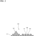
Fig. 2 is an enlarged cross-sectional view taken along the line C-C inFig. 1 . -
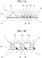
Fig. 3A is a cross-sectional view of a principal part of a mold according to an embodiment. -
Fig. 3B is an enlarged view of the part B inFig. 3A . -
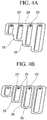
Fig. 4A is a perspective view of a mold-pressing portion of a comparative example. -
Fig. 4B is a perspective view of mold-pressing portions according to the embodiment. -
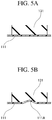
Fig. 5A is a cross-sectional view showing a principal part of the base-material/gasket unit. -
Fig. 5B is a cross-sectional view showing a principal part of a base-material/gasket unit when failure occurs. - A base-material/gasket unit mold according to an embodiment is used to form a base-material/
gasket unit 101 shown inFigs. 1 and2 . - The base-material/
gasket unit 101 includes abase material 111, a gasketmain body 121, and isolatedrubber portions 131. The gasketmain body 121 and theisolated rubber portions 131 are formed on a surface of thebase material 111 by injection molding. The base-material/gasket unit 101 is integrally constructed of thebase material 111, the gasketmain body 121, and the isolatedrubber portions 131. Thebase material 111 is formed of a resin film. The gasketmain body 121 is formed on the surface of thebase material 111 by injection molding. Theisolated rubber portions 131 are formed on the surface of thebase material 111 by injection molding. - The
base material 111 is formed of a resin film having a flat rectangular shape. Thebase material 111 has a hollow portion (cut-out portion) 112 in the central part of the surface. A fuel cell reaction portion will be arranged in thehollow portion 112 when cells are assembled. Thebase material 111 has hollow portions (cut-out portions) 113 in the four corner parts of the surface. Thehollow portions 113 will serve parts of manifold paths when cells are assembled. Exemplary materials of the resin film can be provided by PEN (polyethylene naphthalate), PP (polypropylene), PPSU (polyphenylsulfone), PA (polyamide), and SPS (syndiotactic polystyrene). - The gasket
main body 121 includes an exterior-side gasketmain portion 122 and interior-side gasketmain portions 123. The exterior-side gasketmain portion 122 has a rectangular frame shape. The exterior-side gasketmain portion 122 surrounds the fuel cell reaction portion (hollow portion 112) to prevent leakage of a fluid such as fuel gas or cooling water which is supplied to the fuel cell reaction portion in operation of the fuel cell from the cell. The interior-side gasketmain portions 123 separate the fuel cell reaction portion (hollow portion 112) from the manifold paths (hollow portions 113). - The interior-side gasket
main portions 123 have a notchedopening 124. Theisolated rubber portions 131 serve as a guide or rectifier which facilitates smooth flows of a fluid such as fuel gas or cooling water from thehollow portion 113 to thehollow portion 112 and from thehollow portion 112 to thehollow portion 113 through theopenings 124. - As illustratively shown in
Fig. 1 , a plurality (e.g., four) ofisolated rubber portions 131 having a different length are aligned parallel to each other. Theisolated rubber portions 131 are positioned on thehollow portion 112 side relative to theopening 124. Groove-shaped flow passages 132 are formed between theisolated rubber portions 131 adjacent to each other. Theflow passages 132 are aligned on lines which extend from notches of theopening 124. - As a result, the fluid such as fuel gas can smoothly flow from the
hollow portion 113 through the opening 124 and theflow passages 132 into thehollow portion 112. Also, the fluid can smoothly flow from thehollow portion 112 through theflow passages 124 and theopening 132 into thehollow portion 113. - Exemplary rubber materials which form the gasket
main body 121 and the isolatedrubber portions 131 can be provided by VMQ (vinylmethyl silicone rubber), EPDM (ethylene propylene rubber), and PIB (polyisobutylene). Also, adhesive rubber materials may be used to form the gasketmain body 121 and theisolated rubber portions 131. - The base-material/
gasket unit 101 is formed by inserting thebase material 111 of a resin film as an insert by using an injection mold. - As shown in
Figs. 3A and 3B , aninjection mold 1 includes afirst half mold 11 and asecond half mold 21. Thefirst half mold 11 and thesecond half mold 21 are paired with each other, and used together to close and open the mold of first and second half molds. - A base
material holding portion 12 is arranged on a parting surface of the first half mold 11 (first parting surface). The basematerial holding portion 12 holds thebase material 111 as an insert in place. - A
gasket cavity 22 andisolated rubber cavities 23 are defined on a parting surface side of the second half mold 21 (second parting surface). The gasketmain body 121 is formed on the surface of thebase material 111 by thegasket cavity 22. Theisolated rubber portions 131, which are isolated from the gasketmain body 121, are formed on the surface of thebase material 111 by theisolated rubber cavities 23. The molding rubber material is injected into thecavities gasket body 121 and theisolated rubber portions 131 are formed. - In addition, mold-pressing
portions 24 are arranged on the parting surface of thesecond half mold 21. The mold-pressingportions 24 are arranged on the periphery of their correspondingisolated rubber cavity 23, and press thebase material 111 when the mold is closed. A recessedpart 26 for reducing deformation of the base material is defined as retracted part in apress surface 25 of the mold-pressingportion 24. - More specifically, in the base-material/
gasket unit 101 shown inFigs. 1 and2 , a plurality (e.g., four) ofisolated rubber portions 131 are aligned parallel to each other. To form this arrangement, a plurality (e.g., four) ofisolated rubber cavities 23 for forming theisolated rubber portions 131 are aligned parallel to each other for each set of isolated rubber portions. In this embodiment, the mold-pressingportions 24 are arranged between theisolated rubber cavities 23 adjacent to each other. Accordingly, the recessedpart 26 is arranged in thepress surface 25 of the mold-pressingportion 24. In this embodiment, the recessedparts 26 are aligned as straight grooves parallel to theisolated rubber cavities 23. - A continuous mold-pressing
portion 24 of a comparative example shown inFig. 4A entirely surroundsisolated rubber cavities 23 so that theisolated rubber portions 131 are formed by theisolated rubber cavities 23. Contrary to this, in the mold-pressingportions 24 according to the embodiment shown inFig. 4B , the recessedparts 26 are aligned as straight grooves parallel to theisolated rubber cavities 23 in the press surfaces 25 of the mold-pressingportions 24. In other words, the mold-pressingportions 24 independently surround their correspondingisolated rubber cavity 23. - In molding procedure, the
base material 111 of a film is first placed onto the basematerial holding portion 12 which is arranged in the parting surface of thefirst half mold 11 in the opened mold. Subsequently, the mold is closed. Subsequently, the rubber material is injected into thecavities main body 121 and theisolated rubber portions 131 are formed. After the molding is completed, the mold is opened so that the molded article is removed from the mold. - The
mold 1 according to the embodiment which has the recessedparts 26 in the press surfaces 25 of the mold-pressingportions 24 can provide the following operation/working-effects. - In the case in which the base-material/
gasket unit 101 is formed by using themold 1, the desirableisolated rubber portions 131 can be formed on the flat surface of thebase material 111 without deformation by injection molding as shown inFig. 5A . If the recessedpart 26 is not defined in thepress surface 25 of the mold-pressingportion 24, thebase material 111 may partially be deformed, more specifically bulge toward theisolated rubber portion 131 to a large extent when subjected to high temperature in the molding so that adeformed part 111A appears as shown inFig. 5B . In a case in which theisolated rubber portion 131 is formed on a surface of thedeformed part 111A, molding failure to be eliminated may occur. - To address this, the
mold 1 according to the embodiment has the recessedparts 26 in the press surfaces 25 of the mold-pressingportions 24. Accordingly, thebase material 111 can be deformed not only in the part that faces theisolated rubber cavity 23 but also in the part that faces the recessedpart 26. As a result, thebase material 111 can be deformed both in the part that faces theisolated rubber cavity 23 and in the part that faces the recessedpart 26, that is, the deformation of thebase material 111 can be dispersed. Correspondingly, a deformation extent in the part that faces theisolated rubber cavity 23 can be reduced. Therefore, such a large extent of bulging deformation of thebase material 111 toward theisolated rubber portion 131 can be reduced in the molding. Consequently, molding failure occurrence can be reduced. - In addition, a plurality of
isolated rubber cavities 23 are defined, and the recessedpart 26 is arranged in thepress surface 25 of the mold-pressingportion 24 arranged between the plurality ofisolated rubber cavities 23. For this reason, one recessedpart 26 can reduce deformation of thebase material 111 which may occur both in twoisolated rubber cavities 23 which are located on the both sides of the recessedpart 26. -
- 1 ...
- Mold
- 11 ...
- First Half Mold
- 21 ...
- Second Half Mold
- 12 ...
- Base Material Holding Portion
- 22 ...
- Gasket Cavity
- 23 ...
- Isolated Rubber Cavity
- 24 ...
- Mold-Pressing Portion
- 25 ...
- Press Surface
- 26 ...
- Recessed Part
- 101 ...
- Base-Material/Gasket Unit
- 111 ...
- Base Material
- 112,113 ...
- Hollow Portion
- 121 ...
- Gasket Main Body
- 122 ...
- Exterior-Side Gasket Main Portion
- 123 ...
- Interior-Side Gasket Main Portion
- 124 ...
- Opening
- 131 ...
- Isolated Rubber Portion
- 132 ...
- Flow Passage
Claims (2)
- A base-material/gasket unit mold comprising:a first half mold including a base material holding portion arranged on a first parting surface to hold a base material; anda second half mold having a second parting surface, the second half mold used together with the first half mold to close and open the mold of first and second half molds, the second half mold includinga gasket cavity defined on the second parting surface side to form a gasket main body on a surface of the base material,an isolated rubber cavity defined on the second parting surface side to form an isolated rubber portion isolated from the gasket main body on the surface of the base material, anda mold-pressing portion arranged around the isolated rubber cavity to press the base material when the mold is closed, the mold-pressing portion having a recessed part defined on a press surface side to reduce deformation of the base material.
- The base-material/gasket unit mold according to claim 1, whereinthe second half mold includes a plurality of the isolated rubber cavities, andthe recessed part is arranged between the plurality of isolated rubber cavities adjacent to each other on the press surface side of the mold-pressing portion.
Applications Claiming Priority (2)
| Application Number | Priority Date | Filing Date | Title |
|---|---|---|---|
| JP2019007155 | 2019-01-18 | ||
| PCT/JP2019/045847 WO2020149010A1 (en) | 2019-01-18 | 2019-11-22 | Mold for molding base material integrated gasket |
Publications (4)
| Publication Number | Publication Date |
|---|---|
| EP3912791A1 true EP3912791A1 (en) | 2021-11-24 |
| EP3912791A4 EP3912791A4 (en) | 2022-11-02 |
| EP3912791C0 EP3912791C0 (en) | 2025-04-23 |
| EP3912791B1 EP3912791B1 (en) | 2025-04-23 |
Family
ID=71614290
Family Applications (1)
| Application Number | Title | Priority Date | Filing Date |
|---|---|---|---|
| EP19910618.8A Active EP3912791B1 (en) | 2019-01-18 | 2019-11-22 | Mold for molding base material integrated gasket |
Country Status (5)
| Country | Link |
|---|---|
| US (1) | US11433582B2 (en) |
| EP (1) | EP3912791B1 (en) |
| JP (1) | JP6915174B2 (en) |
| CN (1) | CN111801211B (en) |
| WO (1) | WO2020149010A1 (en) |
Family Cites Families (11)
| Publication number | Priority date | Publication date | Assignee | Title |
|---|---|---|---|---|
| JP2002231274A (en) | 2001-02-01 | 2002-08-16 | Fuji Electric Co Ltd | Polymer electrolyte fuel cell |
| JP4158685B2 (en) | 2003-11-21 | 2008-10-01 | 豊田合成株式会社 | Manufacturing method of molded product with skin material |
| JP2007193971A (en) * | 2006-01-17 | 2007-08-02 | Toyota Motor Corp | Fuel cell |
| JP5077577B2 (en) | 2007-12-07 | 2012-11-21 | 本田技研工業株式会社 | Sealing material for polymer electrolyte fuel cell separator, separator seal and separator |
| JP2010049923A (en) * | 2008-08-21 | 2010-03-04 | Toyota Motor Corp | Method of integrally molding gasket to constituting parts of fuel cell, and device for it |
| JP5349184B2 (en) * | 2009-07-23 | 2013-11-20 | 本田技研工業株式会社 | Fuel cell stack |
| KR101134429B1 (en) * | 2009-08-10 | 2012-04-10 | 기아자동차주식회사 | Separation plate having injection molding gasket |
| CN204431641U (en) | 2014-12-24 | 2015-07-01 | 苏州工业园区协利塑胶有限公司 | A kind of ring-shaped pouring plastic protects the processing mold of inner circle circularity |
| JP6629066B2 (en) | 2015-04-09 | 2020-01-15 | Nok株式会社 | Gasket and manufacturing method thereof |
| JP6696738B2 (en) * | 2015-06-29 | 2020-05-20 | Nok株式会社 | Manufacturing method of substrate integrated gasket |
| KR102159489B1 (en) * | 2017-06-27 | 2020-09-25 | 주식회사 엘지화학 | Mold for manufacturing fuel cell gasket |
-
2019
- 2019-11-22 JP JP2020566129A patent/JP6915174B2/en active Active
- 2019-11-22 WO PCT/JP2019/045847 patent/WO2020149010A1/en not_active Ceased
- 2019-11-22 CN CN201980016678.XA patent/CN111801211B/en active Active
- 2019-11-22 EP EP19910618.8A patent/EP3912791B1/en active Active
- 2019-11-22 US US17/043,946 patent/US11433582B2/en active Active
Also Published As
| Publication number | Publication date |
|---|---|
| US11433582B2 (en) | 2022-09-06 |
| WO2020149010A1 (en) | 2020-07-23 |
| CN111801211B (en) | 2022-03-22 |
| EP3912791A4 (en) | 2022-11-02 |
| CN111801211A (en) | 2020-10-20 |
| JP6915174B2 (en) | 2021-08-04 |
| US20210206038A1 (en) | 2021-07-08 |
| EP3912791C0 (en) | 2025-04-23 |
| JPWO2020149010A1 (en) | 2021-04-30 |
| EP3912791B1 (en) | 2025-04-23 |
Similar Documents
| Publication | Publication Date | Title |
|---|---|---|
| JP4973552B2 (en) | Mold for coating in-mold product and method for coating in-mold product | |
| CN107732271B (en) | fuel cell stack | |
| US10593983B2 (en) | End plate for fuel cell stack | |
| KR20180015149A (en) | Gasket and its manufacturing method | |
| EP2987602B1 (en) | Method for manufacturing substrate-integrated gasket | |
| CN106660238A (en) | Production method for plate-integrated gasket | |
| KR101958108B1 (en) | O-ring forming mold and o-ring formed by thereof | |
| CN106663821A (en) | Plate-integrated gasket manufacturing method | |
| US11433582B2 (en) | Mold for molding base material integrated gasket | |
| CN105121122A (en) | Method for forming liquid elastomer | |
| CN116476334A (en) | A large-format deep-cavity injection mold for plastic parts | |
| JP2014012404A (en) | Injection mold device | |
| KR20180088687A (en) | Gasket and its manufacturing method | |
| CN117656371A (en) | A mold for injection molding | |
| JP2025033670A (en) | Composite member for fuel cell, mold, and method for manufacturing composite member for fuel cell | |
| JP2015042463A (en) | Injection mold | |
| JP4407810B2 (en) | In-mold coating mold | |
| JP2010177022A (en) | Mold for molding gasket of unit cell of fuel cell, method for manufacturing fuel cell, and fuel cell | |
| JP2016150461A (en) | Mold device | |
| JP7231218B2 (en) | injection mold | |
| KR101533080B1 (en) | Injection mold with curved fluid streaming line | |
| CN211993888U (en) | Plastic package forming die | |
| JP2014240161A (en) | Method of producing seal part | |
| CN210046998U (en) | Sinking type positioning ring mechanism with closely matched injection mold | |
| JP2016207445A (en) | Gasket for fuel cell and manufacturing method therefor |
Legal Events
| Date | Code | Title | Description |
|---|---|---|---|
| STAA | Information on the status of an ep patent application or granted ep patent |
Free format text: STATUS: THE INTERNATIONAL PUBLICATION HAS BEEN MADE |
|
| PUAI | Public reference made under article 153(3) epc to a published international application that has entered the european phase |
Free format text: ORIGINAL CODE: 0009012 |
|
| STAA | Information on the status of an ep patent application or granted ep patent |
Free format text: STATUS: REQUEST FOR EXAMINATION WAS MADE |
|
| 17P | Request for examination filed |
Effective date: 20200909 |
|
| AK | Designated contracting states |
Kind code of ref document: A1 Designated state(s): AL AT BE BG CH CY CZ DE DK EE ES FI FR GB GR HR HU IE IS IT LI LT LU LV MC MK MT NL NO PL PT RO RS SE SI SK SM TR |
|
| DAV | Request for validation of the european patent (deleted) | ||
| DAX | Request for extension of the european patent (deleted) | ||
| A4 | Supplementary search report drawn up and despatched |
Effective date: 20220929 |
|
| RIC1 | Information provided on ipc code assigned before grant |
Ipc: B29C 45/14 20060101ALI20220923BHEP Ipc: B29C 33/14 20060101ALI20220923BHEP Ipc: B29C 45/26 20060101AFI20220923BHEP |
|
| GRAP | Despatch of communication of intention to grant a patent |
Free format text: ORIGINAL CODE: EPIDOSNIGR1 |
|
| STAA | Information on the status of an ep patent application or granted ep patent |
Free format text: STATUS: GRANT OF PATENT IS INTENDED |
|
| INTG | Intention to grant announced |
Effective date: 20250129 |
|
| GRAS | Grant fee paid |
Free format text: ORIGINAL CODE: EPIDOSNIGR3 |
|
| GRAA | (expected) grant |
Free format text: ORIGINAL CODE: 0009210 |
|
| STAA | Information on the status of an ep patent application or granted ep patent |
Free format text: STATUS: THE PATENT HAS BEEN GRANTED |
|
| AK | Designated contracting states |
Kind code of ref document: B1 Designated state(s): AL AT BE BG CH CY CZ DE DK EE ES FI FR GB GR HR HU IE IS IT LI LT LU LV MC MK MT NL NO PL PT RO RS SE SI SK SM TR |
|
| REG | Reference to a national code |
Ref country code: GB Ref legal event code: FG4D |
|
| REG | Reference to a national code |
Ref country code: CH Ref legal event code: EP |
|
| REG | Reference to a national code |
Ref country code: DE Ref legal event code: R096 Ref document number: 602019069179 Country of ref document: DE |
|
| REG | Reference to a national code |
Ref country code: IE Ref legal event code: FG4D |
|
| U01 | Request for unitary effect filed |
Effective date: 20250507 |
|
| U07 | Unitary effect registered |
Designated state(s): AT BE BG DE DK EE FI FR IT LT LU LV MT NL PT RO SE SI Effective date: 20250514 |
|
| PG25 | Lapsed in a contracting state [announced via postgrant information from national office to epo] |
Ref country code: ES Free format text: LAPSE BECAUSE OF FAILURE TO SUBMIT A TRANSLATION OF THE DESCRIPTION OR TO PAY THE FEE WITHIN THE PRESCRIBED TIME-LIMIT Effective date: 20250423 |
|
| PG25 | Lapsed in a contracting state [announced via postgrant information from national office to epo] |
Ref country code: NO Free format text: LAPSE BECAUSE OF FAILURE TO SUBMIT A TRANSLATION OF THE DESCRIPTION OR TO PAY THE FEE WITHIN THE PRESCRIBED TIME-LIMIT Effective date: 20250723 Ref country code: GR Free format text: LAPSE BECAUSE OF FAILURE TO SUBMIT A TRANSLATION OF THE DESCRIPTION OR TO PAY THE FEE WITHIN THE PRESCRIBED TIME-LIMIT Effective date: 20250724 |
|
| PG25 | Lapsed in a contracting state [announced via postgrant information from national office to epo] |
Ref country code: PL Free format text: LAPSE BECAUSE OF FAILURE TO SUBMIT A TRANSLATION OF THE DESCRIPTION OR TO PAY THE FEE WITHIN THE PRESCRIBED TIME-LIMIT Effective date: 20250423 |
|
| PG25 | Lapsed in a contracting state [announced via postgrant information from national office to epo] |
Ref country code: HR Free format text: LAPSE BECAUSE OF FAILURE TO SUBMIT A TRANSLATION OF THE DESCRIPTION OR TO PAY THE FEE WITHIN THE PRESCRIBED TIME-LIMIT Effective date: 20250423 |
|
| PG25 | Lapsed in a contracting state [announced via postgrant information from national office to epo] |
Ref country code: RS Free format text: LAPSE BECAUSE OF FAILURE TO SUBMIT A TRANSLATION OF THE DESCRIPTION OR TO PAY THE FEE WITHIN THE PRESCRIBED TIME-LIMIT Effective date: 20250723 |
|
| PG25 | Lapsed in a contracting state [announced via postgrant information from national office to epo] |
Ref country code: IS Free format text: LAPSE BECAUSE OF FAILURE TO SUBMIT A TRANSLATION OF THE DESCRIPTION OR TO PAY THE FEE WITHIN THE PRESCRIBED TIME-LIMIT Effective date: 20250823 |
|
| U20 | Renewal fee for the european patent with unitary effect paid |
Year of fee payment: 7 Effective date: 20251008 |
|
| PGFP | Annual fee paid to national office [announced via postgrant information from national office to epo] |
Ref country code: GB Payment date: 20251001 Year of fee payment: 7 |
|
| PG25 | Lapsed in a contracting state [announced via postgrant information from national office to epo] |
Ref country code: SM Free format text: LAPSE BECAUSE OF FAILURE TO SUBMIT A TRANSLATION OF THE DESCRIPTION OR TO PAY THE FEE WITHIN THE PRESCRIBED TIME-LIMIT Effective date: 20250423 |
|
| PG25 | Lapsed in a contracting state [announced via postgrant information from national office to epo] |
Ref country code: CZ Free format text: LAPSE BECAUSE OF FAILURE TO SUBMIT A TRANSLATION OF THE DESCRIPTION OR TO PAY THE FEE WITHIN THE PRESCRIBED TIME-LIMIT Effective date: 20250423 |
|
| PG25 | Lapsed in a contracting state [announced via postgrant information from national office to epo] |
Ref country code: SK Free format text: LAPSE BECAUSE OF FAILURE TO SUBMIT A TRANSLATION OF THE DESCRIPTION OR TO PAY THE FEE WITHIN THE PRESCRIBED TIME-LIMIT Effective date: 20250423 |
|
| PLBE | No opposition filed within time limit |
Free format text: ORIGINAL CODE: 0009261 |
|
| STAA | Information on the status of an ep patent application or granted ep patent |
Free format text: STATUS: NO OPPOSITION FILED WITHIN TIME LIMIT |
|
| REG | Reference to a national code |
Ref country code: CH Ref legal event code: L10 Free format text: ST27 STATUS EVENT CODE: U-0-0-L10-L00 (AS PROVIDED BY THE NATIONAL OFFICE) Effective date: 20260304 |
|
| 26N | No opposition filed |
Effective date: 20260126 |