JP2016150461A - Mold device - Google Patents
Mold device Download PDFInfo
- Publication number
- JP2016150461A JP2016150461A JP2015027512A JP2015027512A JP2016150461A JP 2016150461 A JP2016150461 A JP 2016150461A JP 2015027512 A JP2015027512 A JP 2015027512A JP 2015027512 A JP2015027512 A JP 2015027512A JP 2016150461 A JP2016150461 A JP 2016150461A
- Authority
- JP
- Japan
- Prior art keywords
- cavity
- mold
- water channel
- movable
- view
- Prior art date
- Legal status (The legal status is an assumption and is not a legal conclusion. Google has not performed a legal analysis and makes no representation as to the accuracy of the status listed.)
- Pending
Links
Images


Abstract
Description
本発明は、例えば駆動モータのステータコアに装着されるカフサといった、円環状の樹脂製品を成形するための金型装置に関する。 The present invention relates to a mold apparatus for molding an annular resin product such as a cuff attached to a stator core of a drive motor.
特許文献1には、カフサを備えた駆動モータに関する技術が開示されている。カフサは、円環状、かつ、偏平薄板状の樹脂製品である。このカフサは、駆動モータにおける円筒形状のステータコアの端面に装着され、ステータコアの内周に設けられる絶縁紙を保護する等の機能を果たす。
この種の樹脂製品の成形においては、その平面度や真円度といった寸法精度を高めることが当然望まれる。そのためには、樹脂製品が成形されるキャビティ内の樹脂圧および温度の均一化を図り、樹脂製品の場所による収縮差を抑えることが必要不可欠である。 In the molding of this type of resin product, it is naturally desirable to increase the dimensional accuracy such as flatness and roundness. For that purpose, it is indispensable to equalize the resin pressure and temperature in the cavity where the resin product is molded, and to suppress the difference in shrinkage depending on the location of the resin product.
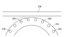
樹脂圧を均一化する対策として、キャビティに対して複数個所から溶融樹脂を充填することで、溶融樹脂の充填バランスをできる限り均一にすることが考えられる。しかし、例えば図10に示すようにして、キャビティ210に溶融樹脂を導くランナー220を平面視でキャビティの環上に複数配置した上で、直線部材であるカートリッジヒーター230によって金型を温度調節する場合、ランナー220とカートリッジヒーター230との干渉が懸念されることからカートリッジヒーター230は図に示す位置よりもキャビティ210の内方側に配置できない。そして、図10においては、カートリッジヒーター230とキャビティ210との距離が図の左右方向へ向かうにしたがって漸増するため、該両側での温度管理が効きにくい。そのため、この対策ではキャビティ210内の樹脂圧及び温度の均一化を両立できない。
As a measure for making the resin pressure uniform, it is conceivable to make the filling balance of the molten resin as uniform as possible by filling the cavity with the molten resin from a plurality of locations. However, for example, as shown in FIG. 10, when a plurality of
本発明は、このような課題を解決しようとするものであって、その目的は、円環状の樹脂製品を成形する金型装置において、キャビティ内の樹脂圧および温度の均一化を共に図り、樹脂製品の寸法精度を向上させることである。 The present invention is intended to solve such a problem, and an object of the present invention is to make the resin pressure and temperature in the cavity uniform in a mold apparatus for molding an annular resin product. It is to improve the dimensional accuracy of the product.
本発明は、上記の目的を達成するためのもので、以下のように構成されている。 The present invention is for achieving the above object, and is configured as follows.
本発明の第1の発明は、金型に設けられる円環状のキャビティに溶融樹脂を充填することによって所定の樹脂製品を成形する金型装置であって、溶融樹脂を射出するスプルーから放射状に分岐して設けられるとともにキャビティに溶融樹脂を導く複数のランナーと、金型の温度を調節する水路と、を備えている。そして、各ランナーは、キャビティに連通される末端部分が、平面視でキャビティの環上周りに対応した位置において該キャビティの周方向に等間隔で設けられている。また、水路は、平面視でキャビティの内周と外周とに対応して設けられている。 A first aspect of the present invention is a mold apparatus for molding a predetermined resin product by filling an annular cavity provided in a mold with a molten resin, and radially diverges from a sprue that injects the molten resin. And a plurality of runners for guiding the molten resin to the cavity and a water channel for adjusting the temperature of the mold. In each runner, end portions communicating with the cavities are provided at equal intervals in the circumferential direction of the cavities at positions corresponding to the periphery of the cavity in a plan view. Moreover, the water channel is provided corresponding to the inner periphery and the outer periphery of the cavity in plan view.
この構成においては、水路がキャビティの内周と外周とに対応して設けられていることから、ランナーがキャビティの環上に対応した位置に複数個設けられているにも関わらず、水路はランナーとの干渉を避けてキャビティに対して周方向に均一、かつ、キャビティに近い位置に配置できる。そのため、キャビティに対して周方向に等間隔で配置された各ランナーから溶融樹脂を充填することによって、溶融樹脂の充填バランスが均一化されてキャビティ内の樹脂圧を均一に近づけることができ、かつ、キャビティの内周及び外周に亘って近い位置に配置された水路による温度調節によって、効果的にキャビティ内の温度を均一に近づけることができる。これらの結果、キャビティ内の樹脂圧および温度の不均一に起因する樹脂製品の場所による収縮差を抑え、樹脂製品の寸法精度を向上させることができる。 In this configuration, since the water channel is provided corresponding to the inner periphery and outer periphery of the cavity, the water channel is the runner even though a plurality of runners are provided at positions corresponding to the ring of the cavity. Can be arranged in a position that is uniform in the circumferential direction with respect to the cavity and close to the cavity. Therefore, by filling the molten resin from the runners arranged at equal intervals in the circumferential direction with respect to the cavity, the filling balance of the molten resin can be made uniform and the resin pressure in the cavity can be made closer to the uniform, and The temperature inside the cavity can be effectively brought close to uniformity by adjusting the temperature with the water channel arranged at a position close to the inner circumference and the outer circumference of the cavity. As a result, it is possible to suppress the difference in shrinkage due to the location of the resin product due to the unevenness of the resin pressure and temperature in the cavity, and to improve the dimensional accuracy of the resin product.
本発明の第2の発明は、第1の発明において、キャビティの中心軸が金型の型開き方向と一致している。そして、水路が、金型の固定金型と可動金型とのそれぞれにおいて平面視でキャビティの内周と外周とに対応して設けられている。 According to a second aspect of the present invention, in the first aspect, the central axis of the cavity coincides with the mold opening direction of the mold. And the water channel is provided corresponding to the inner periphery and the outer periphery of the cavity in a plan view in each of the fixed mold and the movable mold of the mold.
金型装置は、例えば固定金型にランナーを備え、可動金型において樹脂製品を離型させるエジェクターピンを備えている。本発明の第2の発明においては、水路が固定金型と可動金型とのそれぞれにおいてキャビティの内周と外周とに対応して設けられている。このことから、固定金型においては上述のようにしてランナーとの干渉を避けて水路をキャビティに近い位置に配置できる。また、可動金型においては、金型の型開き方向との対応からキャビティの中心軸と平行に延びるエジェクターピンが平面視でキャビティの環上に配置されていても、水路はエジェクターピンとの干渉を避けてキャビティに対して周方向に均一、かつ、キャビティに近い位置に配置できる。そのため、キャビティに対してその中心軸方向の両側から効果的に温度調節ができ、キャビティ内の温度をより一層均一に近づけることができる。 For example, the mold apparatus includes a runner in a fixed mold and an ejector pin that releases a resin product in the movable mold. In the second invention of the present invention, the water channel is provided corresponding to the inner periphery and the outer periphery of the cavity in each of the fixed mold and the movable mold. For this reason, in the fixed mold, the water channel can be disposed at a position close to the cavity while avoiding interference with the runner as described above. In addition, in the movable mold, even if an ejector pin extending in parallel with the central axis of the cavity is arranged on the ring of the cavity in plan view because of the correspondence with the mold opening direction, the water channel does not interfere with the ejector pin. It can avoid and can arrange | position to the position which is uniform in the circumferential direction with respect to the cavity, and close to the cavity. Therefore, the temperature can be effectively adjusted from both sides in the central axis direction with respect to the cavity, and the temperature in the cavity can be made more uniform.
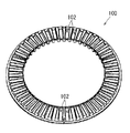
以下、本発明を実施するための形態を、図面を用いて説明する。図2に示す金型装置1においては、樹脂製品であるカフサ100(図1)が成形される。図1に示すように、カフサ100は、円環状、かつ、偏平薄板状の部材である。カフサ100は、その環の部分を厚み方向に貫通した複数のスロット102を周方向に等間隔で備えている。なお、カフサ100の成形材料はポリフェニレンサルファイドである。
Hereinafter, embodiments for carrying out the present invention will be described with reference to the drawings. In the
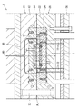
金型装置1は、図2の上側に固定金型10が位置し、図2の下側に可動金型20が位置している。可動金型20は、図示しない可動設備に駆動されることによって、固定金型10に対して接近(型締め)、あるいは離反(型開き)させる作動が可能である。可動金型20の型締め、型開きの作動は、ガイドロッド30に案内される。なお、両金型10,20の合わせ面PLが接合された図2に示す型締め状態では、両金型10,20の間において樹脂製品を成形するキャビティC(図3)が構成されている。キャビティCはカフサ100の形状に対応した円環状に構成され、その中心軸Iが両金型10,20の型開き方向と一致している。
In the
図2において可動金型20の下方にはエジェクタープレート70が位置しており、このエジェクタープレート70は、キャビティCの中心軸Iと平行に延びる複数本のエジェクターピン72を備えている。これらの各エジェクターピン72は、可動金型20を貫通して個々の先端面がキャビティCに臨んでいる(図3)。各エジェクターピン72は、キャビティCの内周側と外周側とにそれぞれ設けられ、該内周側と該外周側とにおいて周方向に等間隔で配置されている(図9)。エジェクタープレート70(図2)は、両金型10,20の型開き時における可動金型20の型開きの作動に対して各エジェクターピン72を相対的に逆方向に作動させる。これによって、各エジェクターピン72がキャビティC内に突出して樹脂製品を押出すように機能する。
In FIG. 2, an
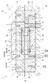
固定金型10(図2)には、該固定金型10を図4〜6の形状に貫通したスプルー40及びランナー50が設けられている。スプルー40は、その先端が射出設備のノズル(図示省略)に連通されて、射出設備から供給される溶融樹脂をキャビティC側へ射出する。ランナー50は、スプルー40の末端から連続して複数に分岐して設けられ、キャビティCに溶融樹脂を導くように構成されている。なお、スプルー40及びランナー50を流れる溶融樹脂は、図示しないホットランナーシステムによって常に流動化状態に保持されている。
The fixed mold 10 (FIG. 2) is provided with a
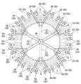
各ランナー50は、スプルー40の末端から放射状に分岐して設けられた6個の主ランナー52と、各主ランナー52の末端において2つずつに分岐して設けられた計12個の中間ランナー54と、各中間ランナー54の末端において2つずつに分岐して設けられた計24個の分岐ランナー56とを備えている(図4〜6)。各分岐ランナー56の主要部は、キャビティCの中心軸Iと平行に延びており、平面視でキャビティCの外周縁に沿う位置で該キャビティCの周方向に等間隔で配置されている。そして、各ランナー50の末端部分となるこれらの分岐ランナー56が、サイドゲートGを介してキャビティCに連通されている。このようにして分岐ランナー56を多数設けることで、各分岐ランナー56間の距離が詰められ、キャビティCに対する溶融樹脂の充填バランスの均一化が促進される。
Each
固定金型10及び可動金型20には、これらの個々を温度調節するための水路90が設けられている(図3,7,8,9)。なお、図8では固定金型10側の水路90がキャビティC及び分岐ランナー56との対応で表されている。また、図9では可動金型20側の水路90がキャビティC、エジェクターピン72、及び分岐ランナー56との対応で表されている。
The fixed
各金型10,20において、水路90は、平面視でキャビティCの内周、環上、外周、にそれぞれ対応して設けられている(図3,7,8,9)。これらの水路90は、固定金型10と可動金型20とでキャビティCを挟んで略対称に設けられ、つまり、キャビティCに対してその中心軸I方向の両側で略対称な位置関係にある。以下、水路90について説明するとき、キャビティCの内周、環上、外周に対応する個々については内周水路90A、環上水路90B、外周水路90Cとして区別し、これらを総称するときは水路90として説明する。
In each
水路90は、各金型10,20を組み込み式に構成することによって形成されている(図3)。詳述すると、固定金型10においては、そのベースとなる固定主型12に対して固定中子14と固定入子16とがこの順に組み込まれている。そして、固定中子14における固定主型12と対向する面において、キャビティCの環上と外周とにそれぞれ対応させて水路用の溝Mが形成されている。これらの各溝Mは、キャビティCに近づくように合わせ面PL側へ深く掘られている。これらの各溝Mの開放面がそれと対向する固定主型12の面で塞がれることで、固定金型10の環上水路90Bと外周水路90Cとがそれぞれ形成されている。
The
固定金型10の環上水路90B及び外周水路90Cと対向する固定主型12の面においては、これらの各水路90A,90Bの脇部に対応させて、シール部材S用の凹部が設けられている。各凹部は対応する水路90A,90Bの全長に亘って設けられ、該凹部にはそれ全長に亘ってゴム製のシール部材Sが埋め込まれている。このシール部材Sが固定主型12と固定中子14との間をシールして、両者12,14の間から各水路90B,90Cの水が漏れ出すことを防止する。以下、図面において統一の符号Sが付された箇所には、ここで説明したのと同じ構成によって凹部に対してシール部材Sが設けられ、個々の箇所において水路90からの水漏れを防止している。なお、これらの個々については重複した説明を省略する。
On the surface of the fixed
固定中子14に設けられた環上水路90B及び外周水路90Cと同様に、固定入子16における固定中子14と対向する面には、キャビティCの内周に対応させて水路用の溝Mが形成されている(図3)。そして、この溝Mの開放面が固定中子14で塞がれることで、固定金型10の内周水路90Aが形成されている。
Similarly to the
つぎに、可動金型20における水路90を説明するが、可動金型20においても、固定金型10と同様にして水路用の溝Mの開放面を対向する面で塞ぐことで水路90が構成されていることから、その詳しい形成方法については重複した説明を省略する。可動金型20においては、そのベースとなる可動主型22に対して、可動中子24、可動第1入子26、可動第2入子28がこの順に組み込まれている(図3)。なお、可動第1入子26は、可動中子24を貫通して可動主型22と対向し、かつ、あわせ面PL側においてはキャビティCを構成している。
Next, the
可動金型20の外周水路90Cは、可動中子24に設けられた溝Mとそれに対向する可動主型22の面とによって形成されている(図3)。また、可動金型20の環上水路90Bは、可動第1入子26に設けられた溝Mと可動主型22の面とによって形成されている。なお、この環上水路90Bは、キャビティCの内周側と外周側とにそれぞれ配置されるエジェクターピン72の間に位置している。可動金型20の内周水路90Aは、可動第1入子26と可動第2入子28とにおいて平面視でキャビティCの内周に亘って相対向して設けられた溝Mがつき合わされて形成されている。
The outer
以上に説明した固定金型10及び可動金型20の各水路90は、それぞれ適宜の2箇所から各金型10,20の外方へ延長され(図7〜9)、個々の先端は図示しない加圧式水源設備に接続されている。そして、加圧式水源設備からの注水によって、各水路90には、例えば約150℃の加圧水が通されている。この加圧水によって、キャビティCが適切な温度で保温される。なお、各水路90の各金型10,20の外方への延長の経路については、図7に示す例に限定されるものではなく、自由に設計変更可能である。
The
上述の構成では、固定金型10においてキャビティCの内周と外周とに対応して内周水路90Aと外周水路90Cとが設けられていることから、固定金型10に設けられた分岐ランナー56がキャビティCの外周縁に沿う位置に複数個設けられているにも関わらず、固定金型10の内周水路90A及び外周水路90Cは分岐ランナー56との干渉を避けてキャビティCに対して周方向に均一、かつ、キャビティCに近い位置に配置できる。そのため、キャビティCに対して周方向に等間隔で配置された各分岐ランナー56から溶融樹脂を充填することによって、溶融樹脂の充填バランスが均一化されてキャビティC内の樹脂圧を均一に近づけることができ、かつ、キャビティCの内周及び外周に亘って近い位置に配置された固定金型10の内周水路90A及び外周水路90Cによる温度調節によって、効果的にキャビティC内の温度を均一に近づけることができる。これらの結果、キャビティC内の樹脂圧および温度の不均一に起因する樹脂製品の場所による収縮差を抑え、樹脂製品の寸法精度を向上させることができる。
In the above-described configuration, since the inner
また、上述の構成では、固定金型10と可動金型20とのそれぞれにおいてキャビティCの内周と外周とに対応して内周水路90Aと外周水路90Cとが設けられていることから、固定金型10においては上述のようにして分岐ランナー56との干渉を避けてこれらの両水路90A,90CをキャビティCに近い位置に配置できる上、可動金型20においては、両金型10,20の型開き方向との対応からキャビティCの中心軸Iと平行に延びるエジェクターピン72が平面視でキャビティCの環上に配置されているにも関わらず、可動金型20の内周水路90A及び外周水路90Cはエジェクターピン72との干渉を避けてキャビティCに対して周方向に均一、かつ、キャビティCに近い位置に配置できる。そのため、キャビティCに対してその中心軸Iの方向の両側から効果的に温度調節ができ、キャビティC内の温度をより一層均一に近づけることができる。
Further, in the above-described configuration, since the inner
また、上述の構成では、上述のようにして固定金型10及び可動金型20のそれぞれにおいてキャビティCの内周と外周とに亘って近い位置に配置された内周水路90Aと外周水路90Cとに加え、固定金型10における分岐ランナー56との干渉を避けた位置、及び、可動金型20におけるエジェクターピン72との干渉を避けた位置において、環上水路90Bが設けられている。このことから、キャビティCに対してその中心軸Iの方向の両側、かつ、キャビティCの内周、環上、外周に対応する位置から効果的に温度調節ができ、キャビティC内の温度が該キャビティCの厚み方向にも周方向にも径方向にも均一化が図られる。
Further, in the above-described configuration, the inner
以上は本発明を実施するための一実施の形態を図面に関連して説明したが、この実施の形態は本発明の趣旨から逸脱しない範囲で容易に変更または変形できるものである。例えば、金型装置1で成形される製品は円環状であればよく、カフサ100に限定されるものではない。つまり、キャビティCの形状は、成形する円環状の樹脂製品に対応して自由に設計変更可能である。
Although one embodiment for carrying out the present invention has been described above with reference to the drawings, this embodiment can be easily changed or modified without departing from the spirit of the present invention. For example, the product molded by the
1 金型装置
10 固定金型
20 可動金型
40 スプルー
50 ランナー
56 分岐ランナー
90 水路
90A 内周水路
90B 環上水路
90C 外周水路
C キャビティ
I 中心軸
DESCRIPTION OF
Claims (2)
溶融樹脂を射出するスプルーから放射状に分岐して設けられるとともにキャビティに溶融樹脂を導く複数のランナーと、金型の温度を調節する水路と、を備え、
各ランナーは、キャビティに連通される末端部分が、平面視でキャビティの環上周りに対応した位置において該キャビティの周方向に等間隔で設けられ、
水路は、平面視でキャビティの内周と外周とに対応して設けられている、
金型装置。 A mold apparatus for molding a predetermined resin product by filling molten resin into an annular cavity provided in a mold,
A plurality of runners that are radially branched from the sprue that injects the molten resin and guides the molten resin to the cavity, and a water channel that adjusts the temperature of the mold,
Each runner is provided at equal intervals in the circumferential direction of the cavity at positions corresponding to the periphery of the cavity ring in plan view, with the end portions communicating with the cavity.
The water channel is provided corresponding to the inner periphery and the outer periphery of the cavity in plan view.
Mold equipment.
キャビティの中心軸が金型の型開き方向と一致し、
水路が、金型の固定金型と可動金型とのそれぞれにおいて平面視でキャビティの内周と外周とに対応して設けられている、
金型装置。
The mold apparatus according to claim 1,
The central axis of the cavity matches the mold opening direction,
Water channels are provided corresponding to the inner periphery and outer periphery of the cavity in plan view in each of the fixed mold and the movable mold of the mold,
Mold equipment.
Priority Applications (1)
| Application Number | Priority Date | Filing Date | Title |
|---|---|---|---|
| JP2015027512A JP2016150461A (en) | 2015-02-16 | 2015-02-16 | Mold device |
Applications Claiming Priority (1)
| Application Number | Priority Date | Filing Date | Title |
|---|---|---|---|
| JP2015027512A JP2016150461A (en) | 2015-02-16 | 2015-02-16 | Mold device |
Publications (1)
| Publication Number | Publication Date |
|---|---|
| JP2016150461A true JP2016150461A (en) | 2016-08-22 |
Family
ID=56695839
Family Applications (1)
| Application Number | Title | Priority Date | Filing Date |
|---|---|---|---|
| JP2015027512A Pending JP2016150461A (en) | 2015-02-16 | 2015-02-16 | Mold device |
Country Status (1)
| Country | Link |
|---|---|
| JP (1) | JP2016150461A (en) |
Cited By (2)
| Publication number | Priority date | Publication date | Assignee | Title |
|---|---|---|---|---|
| CN108501336A (en) * | 2018-06-04 | 2018-09-07 | 上海迪质特信息科技有限公司 | Plastic & rubber blade mould conformal waterway cooling system |
| CN109435161A (en) * | 2018-12-28 | 2019-03-08 | 大连銮艺精密模塑制造有限公司 | Equipped with the multi-faceted mold for reducing surface defects of products through water route |
Citations (3)
| Publication number | Priority date | Publication date | Assignee | Title |
|---|---|---|---|---|
| JPS58179626A (en) * | 1982-04-15 | 1983-10-20 | Sony Corp | Injection molding equipment |
| JPS60182124U (en) * | 1984-05-15 | 1985-12-03 | 不二精機株式会社 | tape reel mold |
| JPH01263016A (en) * | 1988-04-15 | 1989-10-19 | Polyplastics Co | Injection metal mold for cylindrical or columnar molded piece, and molded piece |
-
2015
- 2015-02-16 JP JP2015027512A patent/JP2016150461A/en active Pending
Patent Citations (3)
| Publication number | Priority date | Publication date | Assignee | Title |
|---|---|---|---|---|
| JPS58179626A (en) * | 1982-04-15 | 1983-10-20 | Sony Corp | Injection molding equipment |
| JPS60182124U (en) * | 1984-05-15 | 1985-12-03 | 不二精機株式会社 | tape reel mold |
| JPH01263016A (en) * | 1988-04-15 | 1989-10-19 | Polyplastics Co | Injection metal mold for cylindrical or columnar molded piece, and molded piece |
Cited By (3)
| Publication number | Priority date | Publication date | Assignee | Title |
|---|---|---|---|---|
| CN108501336A (en) * | 2018-06-04 | 2018-09-07 | 上海迪质特信息科技有限公司 | Plastic & rubber blade mould conformal waterway cooling system |
| CN108501336B (en) * | 2018-06-04 | 2024-03-15 | 上海迪质特信息科技有限公司 | Conformal waterway cooling system for plastic impeller mold |
| CN109435161A (en) * | 2018-12-28 | 2019-03-08 | 大连銮艺精密模塑制造有限公司 | Equipped with the multi-faceted mold for reducing surface defects of products through water route |
Similar Documents
| Publication | Publication Date | Title |
|---|---|---|
| US10350803B2 (en) | Injection molding apparatus having cooled core sliders | |
| KR101598129B1 (en) | Standard runner take-out type 3-step injection mold | |
| KR101417621B1 (en) | Injection mold having rapid heating and cooling flow path | |
| JP2016150461A (en) | Mold device | |
| KR101958108B1 (en) | O-ring forming mold and o-ring formed by thereof | |
| US9610722B2 (en) | Hot-runner molding apparatus and hot-runner nozzle | |
| JP2016083781A (en) | Metal mold for insert molding, method of insert-molding using metal mold | |
| JP2003011176A (en) | Valve gate type mold assembly | |
| JP7312159B2 (en) | mold | |
| JP2016074142A (en) | Metal mold for insert molding, and insert molding method using the metal mold | |
| KR20100008869A (en) | Hot runner system and injection molding method using the same | |
| KR100838788B1 (en) | Mold assembly | |
| KR20150106533A (en) | Nozzle and Nozzle Heater Apparatus | |
| CN105377525A (en) | Injection molding method and injection molding die | |
| KR101533080B1 (en) | Injection mold with curved fluid streaming line | |
| JP2005205807A (en) | Mold for injection molding | |
| JP4936490B1 (en) | Injection mold | |
| JP4214587B2 (en) | Injection molding method and injection mold for annular molded product | |
| JP2003136561A (en) | Injection mold for annular molded product and method for molding annular molded product | |
| JP4968606B2 (en) | Injection mold | |
| JP6639270B2 (en) | Manufacturing method of thick molded products | |
| KR101543596B1 (en) | A hot runner device for double injection molding | |
| EP3680084B1 (en) | Mold | |
| JP4203903B2 (en) | Valve gate type mold equipment | |
| JP4062382B2 (en) | Valve gate device |
Legal Events
| Date | Code | Title | Description |
|---|---|---|---|
| A621 | Written request for application examination |
Free format text: JAPANESE INTERMEDIATE CODE: A621 Effective date: 20180125 |
|
| A131 | Notification of reasons for refusal |
Free format text: JAPANESE INTERMEDIATE CODE: A131 Effective date: 20190122 |
|
| A02 | Decision of refusal |
Free format text: JAPANESE INTERMEDIATE CODE: A02 Effective date: 20190716 |