EP3912603A1 - Barrière de stomie convexe - Google Patents
Barrière de stomie convexe Download PDFInfo
- Publication number
- EP3912603A1 EP3912603A1 EP21184581.3A EP21184581A EP3912603A1 EP 3912603 A1 EP3912603 A1 EP 3912603A1 EP 21184581 A EP21184581 A EP 21184581A EP 3912603 A1 EP3912603 A1 EP 3912603A1
- Authority
- EP
- European Patent Office
- Prior art keywords
- convex
- barrier
- flange
- pouch
- core
- Prior art date
- Legal status (The legal status is an assumption and is not a legal conclusion. Google has not performed a legal analysis and makes no representation as to the accuracy of the status listed.)
- Pending
Links
Images


Classifications
-
- A—HUMAN NECESSITIES
- A61—MEDICAL OR VETERINARY SCIENCE; HYGIENE
- A61F—FILTERS IMPLANTABLE INTO BLOOD VESSELS; PROSTHESES; DEVICES PROVIDING PATENCY TO, OR PREVENTING COLLAPSING OF, TUBULAR STRUCTURES OF THE BODY, e.g. STENTS; ORTHOPAEDIC, NURSING OR CONTRACEPTIVE DEVICES; FOMENTATION; TREATMENT OR PROTECTION OF EYES OR EARS; BANDAGES, DRESSINGS OR ABSORBENT PADS; FIRST-AID KITS
- A61F5/00—Orthopaedic methods or devices for non-surgical treatment of bones or joints; Nursing devices; Anti-rape devices
- A61F5/44—Devices worn by the patient for reception of urine, faeces, catamenial or other discharge; Portable urination aids; Colostomy devices
- A61F5/443—Devices worn by the patient for reception of urine, faeces, catamenial or other discharge; Portable urination aids; Colostomy devices having adhesive seals for securing to the body, e.g. of hydrocolloid type, e.g. gels, starches, karaya gums
-
- A—HUMAN NECESSITIES
- A61—MEDICAL OR VETERINARY SCIENCE; HYGIENE
- A61F—FILTERS IMPLANTABLE INTO BLOOD VESSELS; PROSTHESES; DEVICES PROVIDING PATENCY TO, OR PREVENTING COLLAPSING OF, TUBULAR STRUCTURES OF THE BODY, e.g. STENTS; ORTHOPAEDIC, NURSING OR CONTRACEPTIVE DEVICES; FOMENTATION; TREATMENT OR PROTECTION OF EYES OR EARS; BANDAGES, DRESSINGS OR ABSORBENT PADS; FIRST-AID KITS
- A61F5/00—Orthopaedic methods or devices for non-surgical treatment of bones or joints; Nursing devices; Anti-rape devices
- A61F5/44—Devices worn by the patient for reception of urine, faeces, catamenial or other discharge; Portable urination aids; Colostomy devices
- A61F5/451—Genital or anal receptacles
-
- A—HUMAN NECESSITIES
- A61—MEDICAL OR VETERINARY SCIENCE; HYGIENE
- A61F—FILTERS IMPLANTABLE INTO BLOOD VESSELS; PROSTHESES; DEVICES PROVIDING PATENCY TO, OR PREVENTING COLLAPSING OF, TUBULAR STRUCTURES OF THE BODY, e.g. STENTS; ORTHOPAEDIC, NURSING OR CONTRACEPTIVE DEVICES; FOMENTATION; TREATMENT OR PROTECTION OF EYES OR EARS; BANDAGES, DRESSINGS OR ABSORBENT PADS; FIRST-AID KITS
- A61F5/00—Orthopaedic methods or devices for non-surgical treatment of bones or joints; Nursing devices; Anti-rape devices
- A61F5/44—Devices worn by the patient for reception of urine, faeces, catamenial or other discharge; Portable urination aids; Colostomy devices
- A61F5/4404—Details or parts
-
- A—HUMAN NECESSITIES
- A61—MEDICAL OR VETERINARY SCIENCE; HYGIENE
- A61F—FILTERS IMPLANTABLE INTO BLOOD VESSELS; PROSTHESES; DEVICES PROVIDING PATENCY TO, OR PREVENTING COLLAPSING OF, TUBULAR STRUCTURES OF THE BODY, e.g. STENTS; ORTHOPAEDIC, NURSING OR CONTRACEPTIVE DEVICES; FOMENTATION; TREATMENT OR PROTECTION OF EYES OR EARS; BANDAGES, DRESSINGS OR ABSORBENT PADS; FIRST-AID KITS
- A61F5/00—Orthopaedic methods or devices for non-surgical treatment of bones or joints; Nursing devices; Anti-rape devices
- A61F5/44—Devices worn by the patient for reception of urine, faeces, catamenial or other discharge; Portable urination aids; Colostomy devices
- A61F5/445—Colostomy, ileostomy or urethrostomy devices
Definitions
- the following description generally relates to ostomy appliances, and in particular, to an ostomy barrier.
- Ostomy pouches for collecting bodily waste are used by individuals who have had surgery such as a colostomy, ileostomy, or urostomy.
- Two common types of ostomy pouch systems are available, to wit, a one-piece pouch system and a two-piece pouch system.
- an ostomy barrier is permanently attached to a pouch.
- the entire pouch system including the ostomy barrier is removed when a user wants to replace the pouch.
- a pouch and an ostomy barrier are provided as two separate devices.
- the two-piece pouch system typically includes a pair of coupling rings, one of which is fixedly attached to the ostomy barrier, while the other is attached to the pouch.
- the coupling rings are configured to mate with each other, such that the pouch may be securely and removeably attached to the ostomy barrier by engaging the coupling rings together.
- the ostomy barrier is first attached to a user, and the pouch is secured to the faceplate by engaging the coupling rings together.
- Ostomy barriers are configured to seal against peristomal skin surfaces and protect the peristomal surfaces from exposure to stomal effluent.
- the topography of stomas and peristomal surfaces surrounding stomas varies among patients, and sealing an ostomy appliance against such different peristomal surfaces and stomas remain as an area for further improvements.
- a person having a stoma that is flush or recessed may find that applying external support or pressure from a barrier in the peristomal region aids in directing the discharge of effluent from the stoma directly into the ostomy pouch. Accordingly, the effectiveness of an adhesive seal between the ostomy barrier and the peristomal skin surface (i.e., a seal formed by the adhesive layer) may be prolonged.
- the present disclosure provides an improved flexible convex barrier according to various embodiments.
- a convex ostomy barrier for attaching an ostomy appliance to the peristomal skin surrounding a stoma.
- the ostomy barrier may comprise a skin barrier including an adhesive, an inlet opening for receiving a stoma, and a convex insert arranged adjacent the skin barrier.
- the convex insert may have a convex ring-like body and include an inner flange, an outer flange, and a middle portion arranged therebetween.
- the middle portion may include a pouch-side surface, a core-out portion configured to improve the flexibility of the convex insert, and a skin barrier support structure for supporting the skin barrier.
- the inner flange and the outer flange may be arranged in different axial planes to define the convex ring-like body.
- the convex ostomy barrier may also comprise a flange including a body-side coupling ring attached to the pouch-side surface of the convex insert.
- the skin barrier support structure may include a plurality of support structures extending axially from a body-side of the radial wall, wherein the plurality of support structures form a split ring-like shape.
- Each of the plurality of support structures may be surrounded by the core-out portion and include a sloped body-side surface configured to support the skin barrier having a convex body-side surface.
- the core-out portion may be defined by a plurality of core-out windows
- the skin barrier support structure may include a plurality of ribs.
- the plurality of core-out windows and the plurality of ribs may be arranged, such that adjacent ribs are spaced apart from each other by a core-out window therebetween, and each of the core-out windows is defined by a radial wall, an axial wall, and the adjacent ribs.
- the convex insert may include about 8 ribs to about 30 ribs.
- the convex insert may include a radial wall radially extending from the outer flange toward the inlet opening, and an axial wall extending axially from the radial wall in a body-side direction, wherein the inner flange may extend from the axial wall toward the inlet opening.
- the outer flange, the middle portion, and the inner flange may be configured to provide a step-like protrusion in the body-side direction.
- the convex ostomy barrier may also include a tape.
- the convex insert may be attached to a pouch-side of the tape, and the skin barrier may be attached to a body-side of the tape.
- the outer flange may have a concave body-side surface configured to conform to a curved contour of a lower base section of a convex portion of the convex ostomy barrier.
- at least some portion of a body-side surface of the outer flange, the skin barrier support structure, or a body-side surface of the inner flange may be attached to the tape.
- at least the body-side surface of the outer flange may be heat sealed to the tape.
- the middle portion of the convex insert may include a radial wall.
- the pouch-side surface of the middle portion may be defined on a pouch-side of the radial wall.
- the flange may be attached to the convex insert via a flange film, in which the flange film is attached to the pouch side surface.
- the pouch side surface may be generally flat, and the flange film may be heat sealed to the pouch side surface.
- a convex insert for an ostomy barrier having a convex ring-like body may comprise an inlet opening, an inner flange, an outer flange, and a middle portion including a pouch-side surface, a core-out portion configured to improve the flexibility of the convex insert, and a skin barrier support structure.
- the inner flange and the outer flange may be connected by the middle portion and arranged in different axial planes to define the convex-ring like body.
- the convex insert may include a radial wall radially extending from the outer flange toward the inlet opening, and an axial wall extending axially from the radial wall in a body-side direction, wherein the inner flange extends from the axial wall toward the inlet opening.
- the outer flange, the middle portion, and the inner flange may provide a step-like protrusion in the body-side direction.
- the pouch-side surface may be defined on a pouch-side of the radial wall.
- the skin barrier support structure may include a plurality of support structures extending axially from a body-side of the radial wall, wherein the plurality of support structures form a split ring-like shape.
- Each of the plurality of support structures may be surrounded by the core-out portion and include a sloped body-side surface.
- the core-out portion may be defined by a plurality of core-out windows
- the skin barrier support structure may include a plurality of ribs.
- the plurality of core-out windows and the plurality of ribs may be arranged, such that adjacent ribs are spaced apart from each other by a core-out window therebetween, and each of the core-out windows is defined by a radial wall, an axial wall, and the adjacent ribs.
- the skin barrier support structure may include a ring-like structure extending axially from a body-side of the radial wall, and the core-out portion may be defined by two ring-like core-out portions.
- the skin barrier support structure may be arranged between the two ring-like core-out portions and have a sloped body-side surface.
- the skin barrier support structure may include a plurality of rod-like structures or a plurality of tube-like structures extending axially from a body-side surface of the radial wall.
- the core-out portion may be defined by a plurality of openings in the middle section, and the skin barrier structure may be provided between the plurality of openings on the body-side of the middle portion.
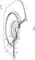
- an ostomy barrier 10 according to an embodiment is shown with a portion removed and viewed from a pouch-side to illustrate a layered construction of the ostomy barrier 10.
- the ostomy barrier 10 may be configured as an ostomy barrier for a two-piece pouch system, and may generally include a skin barrier 12, a flange 16, a convex insert 18, release liners 24, 26, and an inlet opening 28 for receiving a stoma.
- the flange 16 may include a body-side coupling ring 22 for attaching an ostomy pouch.
- the body-side coupling ring 22 may be configured to mate with a pouch-side coupling ring (not shown), such that the ostomy pouch may be mechanically secured to the ostomy barrier 10 when the coupling rings are engaged with each other.
- the flange 16 may be attached to the convex insert 18 via a flange film 30. In the embodiment of FIG. 1 , the flange 16 is attached to a pouch-side surface of the flange film 30 proximate an outer periphery of the flange film 30.
- the convex insert 18 is attached to a body-side surface of the flange film 30 proximate an inner peripheral portion of the flange film 30, such that the flange 16 and the convex insert 18 are attached on the opposite surfaces of the flange film 30 at opposite ends.
- Such a configuration provides a floating flange feature, in which a user may insert his/her finger between the flange 16 and the convex insert 18 to facilitate engagement of the coupling rings to attach a pouch to the ostomy barrier 10.
- the skin barrier 12 may be arranged on the body-side surface of the ostomy barrier 10 for attachment to a user.
- the inlet opening 28 may be defined by an inner periphery of the skin barrier 12 for receiving a stoma (not shown.)
- the skin barrier 12 may be formed from a suitable medical-grade adhesive that can adhesively secure the ostomy barrier 10 to a patient's skin in the peristomal region, such as a hydrocolloid adhesive composition.
- the ostomy barrier 10 may also include a tape 14 including an adhesive layer 32 and a backing layer 34.
- the skin barrier 12 may include a backing layer 36 laminated on the pouch-side surface of the skin barrier 12.
- the backing layer 36 may be formed from a suitable heat sealable polymeric material, such that the backing layer 36 may be heat sealed to the tape 14.
- the skin barrier 12 is attached to a portion of the adhesive layer 32 proximate the inlet opening 28 with the backing layer 36 therebetween.
- an outer peripheral portion of the adhesive layer 32 may be attached to a user surrounding the skin barrier 12 to provide additional security.
- the adhesive layer 32 of the tape 14 may be formed from a suitable medical adhesive, such as an acrylic adhesive.
- the backing layer 34 may be formed from a suitable material, such as a nonwoven material or a thin polymeric film.
- the ostomy barrier 10 may not include the tape 14.
- the skin barrier 12 may be the only means for attaching the ostomy barrier 10 to a user.
- the convex insert 18 is attached to the backing layer 34 of the tape 14 to provide a convexity to the skin barrier 12. In other embodiments, the convex insert 18 may be attached to a pouch-side surface of the skin barrier 12.
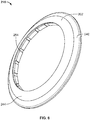
- FIGS. 2-5 are illustrations of the convex insert 18 according to an embodiment.
- the convex insert 18 may be configured to protrude axially toward a body-side direction as shown in FIGS. 1 and 2 to provide a convex ring-like shaped body configured to apply pressure around the peristomal area when the ostomy barrier 10 is attached to a user.
- the convex insert 18 may include an outer flange 40, a middle portion 42, and an inner flange 44, and a radial wall 60 providing a generally flat pouch-side surface 64 on a pouch-side of the convex insert 18 for attachment of the flange 16.
- the outer flange 40 may include a concave body-side surface 50, which is configured to conform to a curved contour of a lower base portion 20 of a convex portion of the skin barrier 12.
- the radial wall 60 including the pouch-side surface 64 is provided in the middle portion 42.
- the middle portion 42 also may include a plurality of core-out windows 54 configured to improve the flexibility of the convex insert 18 and a support structure 52 on the body-side of the convex insert 18 for supporting the skin barrier 12.
- a plurality of ribs 52 may be provided on the body-side to support the skin barrier 12 as shown in FIGS. 1-5 .
- the plurality of ribs 52 and the plurality of core-out windows 54 may be arranged, such that adjacent ribs 52 are spaced apart from each other by a core-out window 54 therebetween.
- Each of the core-out windows 54 may be defined by the radial wall 60, which radially extends from the outer flange 40 toward the inlet opening 28, and an axial wall 62, which axially extends from the radial wall 60 toward a body-side direction, and two adjacent ribs 52.
- the inner flange 44 may radially extend from the axial wall 62 toward the inlet opening 28 as shown in FIGS. 1 and 5 .
- the middle portion 42 is configured to provide a step-like protrusion in the body-side direction from the outer flange 40 to the inner flange 44.
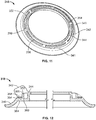
- the lengths of the radial wall 60 and/or axial wall 62 may be adjusted to provide a desired convexity angle ⁇ and a convexity depth D.
- the convex insert 18 may be configured to include about 2 ribs to about 50 ribs, preferably about 4 ribs to about 40 ribs, and more preferably to about 8 ribs to about 30 ribs. In the embodiment of FIG. 3 , the convex insert 18 includes eighteen ribs. As shown, in FIG. 6 , which is an expanded view of the rib 52 and the core-out window 54 of FIGS. 2-5 , each of the rib 52 extends from the outer flange 40 to the inner flange 44. The thickness of each of the rib 52 may taper from the outer flange 40 to the inner flange 44, such that an outer thickness t 1 may be greater than an inner thickness t 2 .
- each of the ribs 52 has an outer thickness t 1 of about 0.099 inches and an inner thickness t 2 of about 0.082 inches.
- each of the rib 52 may be configured to have an outer thickness t 1 of about 0.055 inches and an inner thickness t 2 of about 0.042 inches.
- each of the rib 52 may be configured to have an outer thickness t 1 of about 0.037 inches and an inner thickness t 2 of about 0.020 inches. The number of ribs and the thicknesses of the ribs may be adjusted to provide a desired flexibility of the convex barrier 10.
- the number of the ribs and/or the thicknesses of the ribs may be increase to provide a more rigid convex barrier 10.
- the number of the ribs and/or the thicknesses of the ribs may be decreased to prove a more flexible soft convex barrier 10.
- the flange film 30 may be attached to the pouch-side surface 64 to secure the flange 16 to the convex insert 18.
- the flange film 30 may be heat sealed to the pouch-side surface 64.
- the body-side surfaces of the outer flange 40, the plurality of ribs 52, and the inner flange 44 may be in contact with the tape 14, wherein at least some portions of which are attached to the backing layer 34.
- the body-side surface of the outer flange 40 may be heat sealed to the backing layer 34 of the tape 14.
- an adhesive may be applied on the body-side surface of the convex insert 18 for attachment of the tape 14.
- the convex insert 18 may be formed from a suitable material, such as polymeric materials, rubber, silicone, or metallic materials.
- the convex insert 18 may be formed from a heat sealable thermoplastic material, such as ethylene vinyl acetate (EVA), thermoplastic elastomer, or thermoplastic urethane.
- EVA ethylene vinyl acetate
- the convex insert 18 may be formed from a foam or silicone.
- the convex insert 18 may be formed via thermoforming or other known methods.
- the convex insert 18 may be configured to have a thickness t 3 of about 0.015 inches to about 0.150 inches, preferably about 0.025 inches to about 0.100 inches, and more preferably about 0.030 inches to about 0.080 inches. In the embodiment of FIG.
- the convex insert 18 is configured to have a thickness t 3 of about 0.065 inches. In another embodiment, the convex insert 18 is configured to have a thickness t 3 of about 0.050 inches. In yet another embodiment, the convex insert 18 is configured to have a thickness t 3 of about 0.035 inches.
- a release liner may be provided to cover the skin barrier 12 and the tape 14.
- the release liner 24 is provided to cover an outer peripheral portion of the tape 14, and the release liner 26 is provided to cover the entire body-side surface of the ostomy barrier 10 including the skin barrier 12 and the tape 14.
- the release liner 26 may be removed first for attachment of the skin barrier 12 to peristomal skin, and the release liner 24 may be removed subsequently to expose the tape 14 for further attachment to user's skin.
- body-side surfaces of the radial wall 60 and the axial wall 62 are generally flat, such that an intersection of the radial wall 60 and the axial wall 62 forms a generally 90° angle.
- a body-side surface of the plurality of core-out windows 18 may be curved proximate the intersection.
- FIG. 7 is a cross sectional view of a convex insert 118 including a plurality of core-out windows 154 having a curved body-side surface 163 according to an embodiment.
- the curved body-side surface 163 provides a convex contour similar to the convex outer contour of the ribs 152.
- the body-side surfaces of the radial wall 60 and the axial wall 62 may from a one continuous concave surface similar to the concave body-side surface 50 of the outer flange 40.
- FIGS. 8-10 illustrate a convex insert 218 according to yet another embodiment.
- the convex insert 218 may have convex ring-like shaped body 202 including an outer portion 240 and a convex inner portion 244. As it was with the convex inserts 18, 118, the convex insert 218 may be configured to protrude axially toward a body-side direct as shown in FIGS. 8 and 10 to provide the convex ring-like shaped body.
- the outer portion 240 may include a concave body-side surface 250, while the inner portion 244 may include a convex body-side surface 245.
- the convex insert 218 may also include an axial wall 262 axially extending from a pouch-side surface of the inner portion 244 forming a cylindrical wall structure and a pouch-side surface 264 for attachment of a flange 16 as best shown in FIG. 9 .
- a plurality of windows 254 may be provided along an inner surface 263 of the axial wall 262.
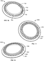
- FIGS. 11 and 12 are illustrations of a convex insert 318 according to an embodiment.
- the convex insert 318 may be configured similar to the convex insert 18 of FIGS. 1-5 including a convex ring-like shaped body for applying pressure around the peristomal area when the ostomy barrier 10 is attached to a user.
- the convex insert 318 may comprise an outer flange 340, a middle portion 342, and an inner flange 344.
- the middle portion may include a radial wall 360 providing a generally flat pouch-side surface 364 for attaching a flange 16, core-out portions 354 configured to improve the flexibility of the convex insert 318, and a plurality of support structures 352 protruding axially from a body-side surface of the radial wall 360 for supporting a skin barrier 12.
- the plurality of support structures 352 forms a split ring-like shape as shown in FIG. 11 .
- the outer flange 340 may extend beyond the radial wall 360 to form a protrusion 341, and each of the plurality of support structures 352 may include a sloped surface 356, such that the inner flange 344, the plurality of support structures 352 and the protrusion 341 may provide a concave line of support 358 shown in phantom lines in FIG. 12 for the skin barrier 12.
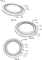
- FIGS. 13-21 are illustrations of convex inserts according to various embodiments. These convex inserts are configured similar to the convex inserts 18, 318 having a convex ring-like shaped body and generally include an outer flange, a middle portion, and an inner flange. The middle portion may include a generally flat pouch-side surface for attaching a flange, core-out portions, and a support structure on the body side for supporting a skin barrier.
- the support structure of these embodiments may be provided in various shapes and forms.
- the convex insert 418 of FIG. 13 may include a support structure 452 that is configured similar to the support structure 352 of FIG. 11 , except the support structure 452 is provided as a single continuous ring-like structure.
- a support structure 552 of the convex insert 518 of FIG. 14 may be configured similar to the support structure 452 of FIG. 13 , except the support structure 552 is provides as a wavy ring-like structure.
- the convex insert 618 of FIG. 15 may be configured similar to the convex insert 18 generally comprising an outer flange 640, a middle portion 642, an inner flange 644, a generally flat pouch-side surface for attachment of a flange and a plurality of support structures 652 for supporting a skin barrier.
- the plurality support structures 652 may be provided as rib-like structures defined between a plurality of core-out windows 654, which may undercut below the inner flange 644 to provide core-out portions thereunder.
- the convex insert 718 of FIG. 16 may comprise a plurality of support structures 752 axially extending from a radial wall 760.
- the plurality of support structures 752 may include a plurality of taller rod-like structures 754 and a plurality of shorter rod-like structures 756.
- the convex insert 718 may include the same number of the taller rod-like structures 754 and the shorter rod-like structures 756.
- the taller rod-like structures 754 may be arranged in a circle concentric to an inlet opening 728, while the shorter rod-like structures 756 may be arranged in a circle surrounding the taller rod-like structures 754 and concentric to the inlet opening 728.
- the taller rod-like structures 754 and the shorter rod-like structures 756 may be aligned radially in pairs as shown in FIG. 16 .
- the each of the taller rod-like structures 754 and the shorter rod-like structures 756 may include a sloped body-side surface configured to provide a support for a skin barrier 12 similar to the plurality of support structures 356 of FIGS. 11 and 12 .
- the convex insert 818 of FIG. 17 may include a plurality of support structures 852 configured similar to the plurality of support structures 752 of FIG. 16 , except taller rod-like structures 854 and shorter rod-like structures 856 are staggered and are not radially aligned in pairs.
- the convex insert 918 of FIG. 18 may comprise a plurality of support structures 952 axially extending from a radial wall 960, each of which having a tube-like body including an opening 954 and a sloped body-side surface 956 for supporting a skin barrier 12.
- 19-21 are similarly configured comprising an outer flange 1040, 1140, 1240, a middle portion 1042, 1142, 1242, an inner flange 1044, 1144, 1244, a generally flat pouch-side surface for attachment of a flange, a plurality of core-out portions 1054, 1154, 1254, and a support structure 1052, 1152, 1252 defined therebetween for supporting the skin barrier 12.
Landscapes
- Health & Medical Sciences (AREA)
- Epidemiology (AREA)
- Nursing (AREA)
- Orthopedic Medicine & Surgery (AREA)
- Engineering & Computer Science (AREA)
- Biomedical Technology (AREA)
- Heart & Thoracic Surgery (AREA)
- Vascular Medicine (AREA)
- Life Sciences & Earth Sciences (AREA)
- Animal Behavior & Ethology (AREA)
- General Health & Medical Sciences (AREA)
- Public Health (AREA)
- Veterinary Medicine (AREA)
- Chemical & Material Sciences (AREA)
- Dispersion Chemistry (AREA)
- Orthopedics, Nursing, And Contraception (AREA)
Applications Claiming Priority (3)
| Application Number | Priority Date | Filing Date | Title |
|---|---|---|---|
| US201662422232P | 2016-11-15 | 2016-11-15 | |
| PCT/US2017/061674 WO2018093815A2 (fr) | 2016-11-15 | 2017-11-15 | Barrière de stomie convexe |
| EP17808687.2A EP3541331B1 (fr) | 2016-11-15 | 2017-11-15 | Barrière de stomie convexe |
Related Parent Applications (2)
| Application Number | Title | Priority Date | Filing Date |
|---|---|---|---|
| EP17808687.2A Division-Into EP3541331B1 (fr) | 2016-11-15 | 2017-11-15 | Barrière de stomie convexe |
| EP17808687.2A Division EP3541331B1 (fr) | 2016-11-15 | 2017-11-15 | Barrière de stomie convexe |
Publications (1)
| Publication Number | Publication Date |
|---|---|
| EP3912603A1 true EP3912603A1 (fr) | 2021-11-24 |
Family
ID=60570231
Family Applications (2)
| Application Number | Title | Priority Date | Filing Date |
|---|---|---|---|
| EP21184581.3A Pending EP3912603A1 (fr) | 2016-11-15 | 2017-11-15 | Barrière de stomie convexe |
| EP17808687.2A Active EP3541331B1 (fr) | 2016-11-15 | 2017-11-15 | Barrière de stomie convexe |
Family Applications After (1)
| Application Number | Title | Priority Date | Filing Date |
|---|---|---|---|
| EP17808687.2A Active EP3541331B1 (fr) | 2016-11-15 | 2017-11-15 | Barrière de stomie convexe |
Country Status (9)
| Country | Link |
|---|---|
| US (1) | US11896515B2 (fr) |
| EP (2) | EP3912603A1 (fr) |
| AU (1) | AU2017359661B2 (fr) |
| CA (1) | CA3041083A1 (fr) |
| DK (1) | DK3541331T3 (fr) |
| ES (1) | ES2888905T3 (fr) |
| HU (1) | HUE056529T2 (fr) |
| LT (1) | LT3541331T (fr) |
| WO (1) | WO2018093815A2 (fr) |
Cited By (1)
| Publication number | Priority date | Publication date | Assignee | Title |
|---|---|---|---|---|
| US11737906B2 (en) | 2019-02-07 | 2023-08-29 | Convatec Technologies, Inc. | Adjustable convex ostomy device |
Families Citing this family (6)
| Publication number | Priority date | Publication date | Assignee | Title |
|---|---|---|---|---|
| US11406525B2 (en) | 2017-11-09 | 2022-08-09 | 11 Health And Technologies Limited | Ostomy monitoring system and method |
| EP3849480A1 (fr) * | 2018-09-12 | 2021-07-21 | Hollister Incorporated | Barrière de stomie convexe et procédé de formation de barrières de stomie convexes de souplesse différente |
| USD893514S1 (en) | 2018-11-08 | 2020-08-18 | 11 Health And Technologies Limited | Display screen or portion thereof with graphical user interface |
| AU2020262496A1 (en) * | 2019-04-25 | 2021-11-18 | Convatec Technologies Inc. | Ostomy wafers incorporating adhesives, ostomy devices including the same, and methods of applying |
| WO2021113435A1 (fr) * | 2019-12-06 | 2021-06-10 | Hollister Incorporated | Appareil de stomie convexe souple |
| US11918508B1 (en) * | 2022-09-01 | 2024-03-05 | Hollister Incorporated | Ostomy appliance for providing customized and localized convex support |
Citations (4)
| Publication number | Priority date | Publication date | Assignee | Title |
|---|---|---|---|---|
| EP0479573A1 (fr) * | 1990-10-03 | 1992-04-08 | E.R. SQUIBB & SONS, INC. | Inséré convexe pour dispositif d'ostomie |
| US5125917A (en) * | 1991-01-04 | 1992-06-30 | William Whealin | Ostomy appliances |
| EP0650709A1 (fr) * | 1993-10-28 | 1995-05-03 | E.R. Squibb & Sons, Inc. | Accouplement d'ostomie |
| WO2012079592A1 (fr) * | 2010-12-17 | 2012-06-21 | Coloplast A/S | Dispositif de support convexe pour un appareil pour stomie |
Family Cites Families (5)
| Publication number | Priority date | Publication date | Assignee | Title |
|---|---|---|---|---|
| US4610676A (en) * | 1984-05-17 | 1986-09-09 | Hollister Incorporated | Ostomy appliance coupling ring construction |
| GB2181652A (en) * | 1985-10-21 | 1987-04-29 | John Victor Edwards | Ostomy appliance |
| DK170739B1 (da) * | 1992-03-20 | 1996-01-08 | Coloplast As | Konveks-ring til brug sammen med stomiudstyr |
| DK171342B1 (da) * | 1994-03-11 | 1996-09-16 | Coloplast As | Stomiudstyr omfattende et ringformet legeme med enkonveks proximal side, som er forsynet med et klæbemiddel |
| DE202005015157U1 (de) * | 2005-09-26 | 2006-05-24 | Tashlyk, Oleksandr | Basisplatte |
-
2017
- 2017-11-15 US US16/341,227 patent/US11896515B2/en active Active
- 2017-11-15 CA CA3041083A patent/CA3041083A1/fr active Pending
- 2017-11-15 WO PCT/US2017/061674 patent/WO2018093815A2/fr unknown
- 2017-11-15 EP EP21184581.3A patent/EP3912603A1/fr active Pending
- 2017-11-15 DK DK17808687.2T patent/DK3541331T3/da active
- 2017-11-15 HU HUE17808687A patent/HUE056529T2/hu unknown
- 2017-11-15 LT LTEPPCT/US2017/061674T patent/LT3541331T/lt unknown
- 2017-11-15 EP EP17808687.2A patent/EP3541331B1/fr active Active
- 2017-11-15 ES ES17808687T patent/ES2888905T3/es active Active
- 2017-11-15 AU AU2017359661A patent/AU2017359661B2/en active Active
Patent Citations (4)
| Publication number | Priority date | Publication date | Assignee | Title |
|---|---|---|---|---|
| EP0479573A1 (fr) * | 1990-10-03 | 1992-04-08 | E.R. SQUIBB & SONS, INC. | Inséré convexe pour dispositif d'ostomie |
| US5125917A (en) * | 1991-01-04 | 1992-06-30 | William Whealin | Ostomy appliances |
| EP0650709A1 (fr) * | 1993-10-28 | 1995-05-03 | E.R. Squibb & Sons, Inc. | Accouplement d'ostomie |
| WO2012079592A1 (fr) * | 2010-12-17 | 2012-06-21 | Coloplast A/S | Dispositif de support convexe pour un appareil pour stomie |
Cited By (1)
| Publication number | Priority date | Publication date | Assignee | Title |
|---|---|---|---|---|
| US11737906B2 (en) | 2019-02-07 | 2023-08-29 | Convatec Technologies, Inc. | Adjustable convex ostomy device |
Also Published As
| Publication number | Publication date |
|---|---|
| EP3541331A2 (fr) | 2019-09-25 |
| CA3041083A1 (fr) | 2018-05-24 |
| AU2017359661A1 (en) | 2019-05-02 |
| LT3541331T (lt) | 2021-09-27 |
| WO2018093815A2 (fr) | 2018-05-24 |
| WO2018093815A3 (fr) | 2018-10-04 |
| AU2017359661B2 (en) | 2022-11-24 |
| US20190254864A1 (en) | 2019-08-22 |
| ES2888905T3 (es) | 2022-01-10 |
| HUE056529T2 (hu) | 2022-02-28 |
| DK3541331T3 (da) | 2021-09-13 |
| EP3541331B1 (fr) | 2021-08-25 |
| US11896515B2 (en) | 2024-02-13 |
Similar Documents
| Publication | Publication Date | Title |
|---|---|---|
| AU2017359661B2 (en) | Convex ostomy barrier | |
| US20210307952A1 (en) | Convex ostomy barrier and method of forming convex ostomy barriers of various softness | |
| AU2017362258B2 (en) | Ostomy barrier | |
| EP3454796B1 (fr) | Éléments de montage à pétales multiples pour poches de stomie | |
| US20230329895A1 (en) | Adjustable convexity ostomy barrier | |
| EP2496193B1 (fr) | Scellement étanche pour un appareil de stomie | |
| EP0317326A2 (fr) | Instrument d'ostomie et son anneau convexe de pression | |
| EP2554142B1 (fr) | Appareillage stomique avec pattes de ceinture intégrée | |
| EP2568932B1 (fr) | Structure d'étanchéité équipée de cordon(s) à action négative, conçue pour une poche de stomie | |
| EP3445296B1 (fr) | Barriere pour stomie |
Legal Events
| Date | Code | Title | Description |
|---|---|---|---|
| PUAI | Public reference made under article 153(3) epc to a published international application that has entered the european phase |
Free format text: ORIGINAL CODE: 0009012 |
|
| STAA | Information on the status of an ep patent application or granted ep patent |
Free format text: STATUS: THE APPLICATION HAS BEEN PUBLISHED |
|
| AC | Divisional application: reference to earlier application |
Ref document number: 3541331 Country of ref document: EP Kind code of ref document: P |
|
| AK | Designated contracting states |
Kind code of ref document: A1 Designated state(s): AL AT BE BG CH CY CZ DE DK EE ES FI FR GB GR HR HU IE IS IT LI LT LU LV MC MK MT NL NO PL PT RO RS SE SI SK SM TR |
|
| B565 | Issuance of search results under rule 164(2) epc |
Effective date: 20211026 |
|
| STAA | Information on the status of an ep patent application or granted ep patent |
Free format text: STATUS: REQUEST FOR EXAMINATION WAS MADE |
|
| 17P | Request for examination filed |
Effective date: 20220518 |
|
| RBV | Designated contracting states (corrected) |
Designated state(s): AL AT BE BG CH CY CZ DE DK EE ES FI FR GB GR HR HU IE IS IT LI LT LU LV MC MK MT NL NO PL PT RO RS SE SI SK SM TR |
|
| P01 | Opt-out of the competence of the unified patent court (upc) registered |
Effective date: 20230520 |