EP3911973B1 - Verbesserte kollisionsdetektion für ein roboterarbeitswerkzeug - Google Patents
Verbesserte kollisionsdetektion für ein roboterarbeitswerkzeug Download PDFInfo
- Publication number
- EP3911973B1 EP3911973B1 EP20700673.5A EP20700673A EP3911973B1 EP 3911973 B1 EP3911973 B1 EP 3911973B1 EP 20700673 A EP20700673 A EP 20700673A EP 3911973 B1 EP3911973 B1 EP 3911973B1
- Authority
- EP
- European Patent Office
- Prior art keywords
- robotic lawnmower
- distance
- robotic
- sensed
- radar device
- Prior art date
- Legal status (The legal status is an assumption and is not a legal conclusion. Google has not performed a legal analysis and makes no representation as to the accuracy of the status listed.)
- Active
Links
Images


Classifications
-
- G—PHYSICS
- G05—CONTROLLING; REGULATING
- G05D—SYSTEMS FOR CONTROLLING OR REGULATING NON-ELECTRIC VARIABLES
- G05D1/00—Control of position, course, altitude or attitude of land, water, air or space vehicles, e.g. using automatic pilots
- G05D1/40—Control within particular dimensions
- G05D1/43—Control of position or course in two dimensions [2D]
-
- G—PHYSICS
- G01—MEASURING; TESTING
- G01S—RADIO DIRECTION-FINDING; RADIO NAVIGATION; DETERMINING DISTANCE OR VELOCITY BY USE OF RADIO WAVES; LOCATING OR PRESENCE-DETECTING BY USE OF THE REFLECTION OR RERADIATION OF RADIO WAVES; ANALOGOUS ARRANGEMENTS USING OTHER WAVES
- G01S13/00—Systems using the reflection or reradiation of radio waves, e.g. radar systems; Analogous systems using reflection or reradiation of waves whose nature or wavelength is irrelevant or unspecified
- G01S13/88—Radar or analogous systems specially adapted for specific applications
- G01S13/881—Radar or analogous systems specially adapted for specific applications for robotics
-
- A—HUMAN NECESSITIES
- A01—AGRICULTURE; FORESTRY; ANIMAL HUSBANDRY; HUNTING; TRAPPING; FISHING
- A01D—HARVESTING; MOWING
- A01D34/00—Mowers; Mowing apparatus of harvesters
- A01D34/006—Control or measuring arrangements
- A01D34/008—Control or measuring arrangements for automated or remotely controlled operation
-
- A—HUMAN NECESSITIES
- A01—AGRICULTURE; FORESTRY; ANIMAL HUSBANDRY; HUNTING; TRAPPING; FISHING
- A01D—HARVESTING; MOWING
- A01D34/00—Mowers; Mowing apparatus of harvesters
- A01D34/01—Mowers; Mowing apparatus of harvesters characterised by features relating to the type of cutting apparatus
- A01D34/412—Mowers; Mowing apparatus of harvesters characterised by features relating to the type of cutting apparatus having rotating cutters
- A01D34/42—Mowers; Mowing apparatus of harvesters characterised by features relating to the type of cutting apparatus having rotating cutters having cutters rotating about a horizontal axis, e.g. cutting-cylinders
- A01D34/54—Cutting-height adjustment
-
- G—PHYSICS
- G01—MEASURING; TESTING
- G01B—MEASURING LENGTH, THICKNESS OR SIMILAR LINEAR DIMENSIONS; MEASURING ANGLES; MEASURING AREAS; MEASURING IRREGULARITIES OF SURFACES OR CONTOURS
- G01B15/00—Measuring arrangements characterised by the use of electromagnetic waves or particle radiation, e.g. by the use of microwaves, X-rays, gamma rays or electrons
- G01B15/02—Measuring arrangements characterised by the use of electromagnetic waves or particle radiation, e.g. by the use of microwaves, X-rays, gamma rays or electrons for measuring thickness
-
- G—PHYSICS
- G01—MEASURING; TESTING
- G01S—RADIO DIRECTION-FINDING; RADIO NAVIGATION; DETERMINING DISTANCE OR VELOCITY BY USE OF RADIO WAVES; LOCATING OR PRESENCE-DETECTING BY USE OF THE REFLECTION OR RERADIATION OF RADIO WAVES; ANALOGOUS ARRANGEMENTS USING OTHER WAVES
- G01S13/00—Systems using the reflection or reradiation of radio waves, e.g. radar systems; Analogous systems using reflection or reradiation of waves whose nature or wavelength is irrelevant or unspecified
- G01S13/02—Systems using reflection of radio waves, e.g. primary radar systems; Analogous systems
- G01S13/06—Systems determining position data of a target
- G01S13/08—Systems for measuring distance only
- G01S13/10—Systems for measuring distance only using transmission of interrupted, pulse modulated waves
-
- G—PHYSICS
- G01—MEASURING; TESTING
- G01S—RADIO DIRECTION-FINDING; RADIO NAVIGATION; DETERMINING DISTANCE OR VELOCITY BY USE OF RADIO WAVES; LOCATING OR PRESENCE-DETECTING BY USE OF THE REFLECTION OR RERADIATION OF RADIO WAVES; ANALOGOUS ARRANGEMENTS USING OTHER WAVES
- G01S13/00—Systems using the reflection or reradiation of radio waves, e.g. radar systems; Analogous systems using reflection or reradiation of waves whose nature or wavelength is irrelevant or unspecified
- G01S13/87—Combinations of radar systems, e.g. primary radar and secondary radar
-
- G—PHYSICS
- G05—CONTROLLING; REGULATING
- G05D—SYSTEMS FOR CONTROLLING OR REGULATING NON-ELECTRIC VARIABLES
- G05D1/00—Control of position, course, altitude or attitude of land, water, air or space vehicles, e.g. using automatic pilots
- G05D1/02—Control of position or course in two dimensions
- G05D1/021—Control of position or course in two dimensions specially adapted to land vehicles
- G05D1/0257—Control of position or course in two dimensions specially adapted to land vehicles using a radar
-
- G—PHYSICS
- G05—CONTROLLING; REGULATING
- G05D—SYSTEMS FOR CONTROLLING OR REGULATING NON-ELECTRIC VARIABLES
- G05D1/00—Control of position, course, altitude or attitude of land, water, air or space vehicles, e.g. using automatic pilots
- G05D1/20—Control system inputs
- G05D1/24—Arrangements for determining position or orientation
- G05D1/242—Means based on the reflection of waves generated by the vehicle
-
- A—HUMAN NECESSITIES
- A01—AGRICULTURE; FORESTRY; ANIMAL HUSBANDRY; HUNTING; TRAPPING; FISHING
- A01D—HARVESTING; MOWING
- A01D2101/00—Lawn-mowers
-
- G—PHYSICS
- G01—MEASURING; TESTING
- G01S—RADIO DIRECTION-FINDING; RADIO NAVIGATION; DETERMINING DISTANCE OR VELOCITY BY USE OF RADIO WAVES; LOCATING OR PRESENCE-DETECTING BY USE OF THE REFLECTION OR RERADIATION OF RADIO WAVES; ANALOGOUS ARRANGEMENTS USING OTHER WAVES
- G01S13/00—Systems using the reflection or reradiation of radio waves, e.g. radar systems; Analogous systems using reflection or reradiation of waves whose nature or wavelength is irrelevant or unspecified
- G01S13/02—Systems using reflection of radio waves, e.g. primary radar systems; Analogous systems
- G01S13/06—Systems determining position data of a target
- G01S13/08—Systems for measuring distance only
-
- G—PHYSICS
- G01—MEASURING; TESTING
- G01S—RADIO DIRECTION-FINDING; RADIO NAVIGATION; DETERMINING DISTANCE OR VELOCITY BY USE OF RADIO WAVES; LOCATING OR PRESENCE-DETECTING BY USE OF THE REFLECTION OR RERADIATION OF RADIO WAVES; ANALOGOUS ARRANGEMENTS USING OTHER WAVES
- G01S13/00—Systems using the reflection or reradiation of radio waves, e.g. radar systems; Analogous systems using reflection or reradiation of waves whose nature or wavelength is irrelevant or unspecified
- G01S13/87—Combinations of radar systems, e.g. primary radar and secondary radar
- G01S13/874—Combination of several systems for attitude determination
-
- G—PHYSICS
- G05—CONTROLLING; REGULATING
- G05D—SYSTEMS FOR CONTROLLING OR REGULATING NON-ELECTRIC VARIABLES
- G05D1/00—Control of position, course, altitude or attitude of land, water, air or space vehicles, e.g. using automatic pilots
- G05D1/60—Intended control result
- G05D1/648—Performing a task within a working area or space, e.g. cleaning
Definitions
- This application relates to robotic work tools and in particular to a system and a method for performing improved lift detection, such as a lawnmower.
- Automated or robotic power tools such as robotic lawnmowers are becoming increasingly more popular.
- a work area such as a garden
- the robotic lawnmower is typically configured to work inside the work area during a large portion of the year.
- the robotic lawnmower is working outside and will be subjected to weather, dirt, cut grass and other debris, it is important to protect the components of a robotic lawnmower.
- all robotic lawnmowers are equipped with lift detection devices that ensures that a lift of the robotic lawnmower is detected within 10 mm lifting height and the cutters may be turned off to prevent or reduce the risk of damage.
- Such lift detectors are commonly mechanical or electromechanical devices, where one part is attached to an upper part of the robotic lawnmower and a second part is attached to a lower part of the robotic lawnmower.
- a lift is detected when the upper part moves in relation to the lower part, i.e. when the first part of the lift detector moves in relation to the second part of the lift detector.
- the lift detection thus requires that the robotic lawnmower has two cover parts that are movable with regards to one another, which in turn renders the robotic lawnmower susceptible to being contaminated by water, dirt or other debris coming in between the two cover parts and risking to damage or cause increased wear of components of the robotic lawnmower. This is also an expensive solution to implement.
- the coherent body part may consist of several parts, such as an outer cover attached to a chassis.
- the body or its parts does not need to be movable relative to itself, as in the body parts are not movable relative each other, the body may be sealed in a more efficient manner .
- the outer cover need not be movable relative the chassis.
- FIG 1A shows a perspective view of a robotic working tool 100, here exemplified by a robotic lawnmower 100, having a body 140 and a plurality of wheels 130 (only one shown).
- the robotic lawnmower 100 may comprise charging skids for contacting contact plates (not shown in figure 1 ) when docking into a charging station (not shown in figure 1 , but referenced 210 in figure 2 ) for receiving a charging current through, and possibly also for transferring information by means of electrical communication between the charging station and the robotic lawnmower 100.
- FIG. 1B shows a schematic overview of the robotic working tool 100, also exemplified here by a robotic lawnmower 100, having a body 140 and a plurality of wheels 130.
- the robotic lawnmower 100 has four wheels 130, two front wheels 130' and the rear wheels 130". At least some of the wheels 130 are drivably connected to at least one electric motor 150.
- electric motor 150 It should be noted that even if the description herein is focused on electric motors, combustion engines may alternatively be used, possibly in combination with an electric motor.
- each of the rear wheels 130" is connected to a respective electric motor 150. This allows for driving the rear wheels 130" independently of one another which, for example, enables steep turning.
- the robotic lawnmower 100 also comprises a grass cutting device 160, such as a rotating blade 160 driven by a cutter motor 165.
- the grass cutting device being an example of a work tool 160 for a robotic work tool 100.
- the robotic lawnmower 100 also has (at least) one battery 180 for providing power to the motors 150 and the cutter motor 165.
- the robotic lawnmower 100 also comprises a controller 110 and a computer readable storage medium or memory 120.
- the controller 110 may be implemented using instructions that enable hardware functionality, for example, by using executable computer program instructions in a general-purpose or special-purpose processor that may be stored on the memory 120 to be executed by such a processor.
- the controller 110 is configured to read instructions from the memory 120 and execute these instructions to control the operation of the robotic lawnmower 100 including, but not being limited to, the propulsion of the robotic lawnmower.
- the controller 110 may be implemented using any suitable, available processor or Programmable Logic Circuit (PLC).
- PLC Programmable Logic Circuit
- the memory 120 may be implemented using any commonly known technology for computer-readable memories such as ROM, RAM, SRAM, DRAM, FLASH, DDR, SDRAM or some other memory technology.
- the robotic lawnmower 100 may further be arranged with a wireless communication interface 115 for communicating with other devices, such as a server, a personal computer or smartphone, or the charging station.
- wireless communication devices such as Bluetooth ® , Global System Mobile (GSM) and LTE (Long Term Evolution), to name a few.
- the robotic lawnmower 100 may be further configured to have at least one magnetic sensor 170 arranged to detect a magnetic field (not shown) and for detecting a boundary cable and/or for receiving (and possibly also sending) information from a signal generator (will be discussed with reference to figure 2 ).
- the sensors 170 may be connected to the controller 110, and the controller 110 may be configured to process and evaluate any signals received from the sensors 170.
- the sensor signals may be caused by the magnetic field being generated by a control signal being transmitted through a boundary cable. This enables the controller 110 to determine whether the robotic lawnmower 100 is close to or crossing a boundary cable, or inside or outside an area enclosed by the boundary cable.
- the magnetic sensor(s) 170 as well as the boundary cable (referenced 230 in figure 2 ) and any signal generator(s) are optional as is indicated by the dashed line of the boundary cable (230) in figure 2 .
- the boundary cable may alternatively be used as the main and only perimeter marker.
- the boundary cable may alternatively simply be used as an additional safety measure.
- the boundary cable may alternatively be used as the main perimeter marker and other navigation sensors (see below) are used for more detailed or advanced operation.
- the robotic lawnmower 100 may further comprise at least one beacon navigation sensor 175, such as an Ultra Wide Band (UWB) sensor, configured to receive signals from a Radio Frequency beacon, such as a UWB beacon.
- UWB Ultra Wide Band
- the robotic lawnmower 100 may also comprise at least one satellite navigation sensor, such as a Global Positioning System (GPS) device 185, or a GLONASS device.
- GPS Global Positioning System
- GLONASS Global Navigation Satellite System
- the robotic lawnmower 100 also comprises at least one radar device 190.
- Two 190' are arranged in the vicinity of the front wheels 130' and two are arranged in the vicinity of the rear wheel 130".
- the radar device 190 may be arranged in font, behind or next to a wheel. It should also be noted that even if the example of figure 1B shows four radar devices 190', 190" each arranged in the vicinity of a wheel, other numbers of radar devices 190 may be possible.
- one radar device 190 is arranged at the front or the middle of the robotic lawnmower 100.
- two radar devices 190 are arranged, one at the front and one at the rear of the robotic lawnmower 100.
- Radar is a detection system that uses radio waves to determine the range, angle, or velocity of obj ects.
- the radar operates by transmitting a short radio pulse in a direction. The direction is determined by the directivity of an antenna of the radar device. If there is an obstacle in the direction of the radio pulse, the energy of the radar pulse is scattered in all directions. A portion of the scattered energy is, however, reflected - or echoed - back to the radar. The radar pulse is thereby reflected by the object. The reflected pulse is sometimes referred to as the echo or radar echo.
- a distance to the object can be determined by measuring the time from transmission of the radar pulse to reception of the reflected pulse.
- a non-contact sensor such as an acoustic sensor, an optic sensor or a high precision radar device
- a sturdy and robust lift detection system may be provided.
- a non-contact sensor pulse such as an acoustic pulse
- an optical pulse when the body is provided with a window
- a radar pulse will be able to penetrate the body 140 of the robotic lawnmower 100 there is no need for the prior art systems where one body part (for example the cover) was arranged movable relative another body part (for example the chassis).
- the body 140 can thus be constructed to be one coherent piece. Using a coherent body 140 simplifies production and protects the robotic lawnmower from any debris, wet grass, dirt or other debris.
- the body 140 may still be made from different body parts, but utilizing the teachings herein, the body parts may be sealed in a more efficient manner as they do not need to be movable relative each other any longer.
- a coherent body is to be understood as a body where the body parts are not movable relative one another, such as where a chassis, provided with the wheels, and an outer cover are sealed and need not be arranged to be movable relative one another.
- Figure 3A shows the outer cover 140-1 and the chassis 140-2. Together the chassis and the outer cover thus form the outer body inside which most components are carried in the robotic lawnmower, especially components such as the controller and the batteries.
- the outer cover is a cover on the outmost side of the robotic lawnmower.
- the radar device is one example of a non-contact distance sensor that may be used to detect the distance to the surface travelled.
- Other examples include optical sensors such as infrared (IR) sensors, Laser or Lidar sensors to mention a few, and acoustic sensors.
- Using radar brings about several additional advantages over such optical sensors as there is no need for any openings or lens covered openings through which an infrared or other light signal may be projected through.
- Using radar brings about benefits over acoustic signals as acoustic signals may be dampened by dirt, grass or other debris stuck to the under carriage of the chassis. This simplifies the placement of the radar device.
- the radar device 190 also brings about the advantage over optical distance determining devices, such as LASER, LIDAR or InfraRed in that radar has a relatively wide beam width, or lobe, which enables distance determination even when the robotic lawnmower is tilted.
- the radar device is also insensitive to any incident light from other light sources. And the radar device cannot be clogged by dirt and other debris.
- the radar device 190 is arranged so that it is directed towards the surface travelled, i.e. the ground.
- the radar device is therefore substantially directed downwards or in other words towards the ground under the robotic lawnmower 100, and not in front, behind or on the side of the robotic lawnmower 100.
- the radar device 190 is directed within +/- 5 degrees parallel to a normal to the surface travelled (G). In one embodiment the radar device 190 is thus not directed in a direction of travel for the robotic lawnmower 100.
- the robotic lawnmower 100 also comprises a tilt detection device, such as an accelerometer or a gyro 195.
- FIG 2 shows a schematic view of a robotic working tool system 200 in one embodiment.
- the schematic view is not to scale.
- the robotic working tool system 200 comprises a charging station 210 and a robotic working tool 100.
- the robotic working tool is exemplified by a robotic lawnmower, whereby the robotic work tool system may be a robotic lawnmower system or a system comprising a combinations of robotic work tools, one being a robotic lawnmower, but the teachings herein may also be applied to other robotic working tools adapted to operate within a work area.
- the robotic working tool system 220 may also optionally comprise a boundary cable 230 arranged to enclose a work area 205, in which the robotic lawnmower 100 is supposed to serve.
- the robotic working tool system 220 may also optionally comprise at least one beacon 220 to enable the robotic lawnmower to navigate the work area using the beacon navigation sensor 175.
- the robotic lawnmower 100 may use the satellite navigation device 185, possibly supported by a deduced reckoning navigation sensor (not shown) to navigate the work area 205.
- the work area 205 is in this application exemplified as a garden, but can also be other work areas as would be understood.
- the garden contains a number of obstacles (O), exemplified herein by a house (O:HOUSE) and a garage (O:GARAGE) that are surrounded by a lawn. In front of the garage there is a drive way and a small path leads to the house from the driveway.
- O:HOUSE a house
- O:GARAGE a garage
- T trees
- the trees are marked both with respect to their trunks (filled lines) and the extension of their foliage (dashed lines).
- Figure 3A shows a schematic view of an example embodiment of a robotic work tool, being a robotic lawnmower 100, according to the teachings herein.
- the robotic lawnmower 100 is traversing or travelling over a surface referenced G.
- a surface For the example of a robotic lawnmower 100, the surface is most likely the ground.
- a radar device 190 is arranged within the robotic lawnmower 100, the radar device being directed downwards towards the surface travelled. Even though the radar device 190 is shown as being arranged on the upper part or ceiling of the body 140 of the robotic lawnmower 100, it should be noted that this is only for illustrative purposes enabling details to be shown without cluttering smaller areas of the figure. It should also be noted that the example of figure 3A only relates to one radar device 190, but the teachings may also be used for embodiments utilizing or comprising several radar devices. See for example figures 4A and 4B for some details.
- the radar device 190 is at a first distance from the ground G, i.e. the surface travelled.
- the first distance is referenced D in figure 3A and indicated by the arrow.
- the distance D is taken to be a normative distance to the ground.
- the normative distance D may be an interval of distances, or it may be a determined average distance.
- the normative distance may be determined by the controller upon start-up, in one such embodiment before the robotic lawnmower leaves the charging station.
- the normative distance may be determined by the controller when the controller determines that the robotic lawnmower is travelling over a smooth surface, for example a garden path.
- the controller may be configured to determine that the surface being travelled is smooth by determining that vibrations are below a threshold level. The vibrations may be measured through the accelerometer 195.
- FIG. 3B shows a schematic view of an example embodiment of a robotic work tool, being a robotic lawnmower 100, according to the teachings herein.
- the robotic lawnmower 100 has been lifted of the ground G.
- the robotic lawnmower 100 determines the distance to the ground by determining a sensed distance SD.
- the robotic lawnmower 100 is configured to determine or measure this sensed distance SD utilizing the radar device 190 by transmitting radar pulses and detecting echoes, or reflected pulses, and based on the time difference, determine the sensed distance SD.
- the robotic lawnmower is configured to compare the sensed distance to a threshold distance.
- the threshold distance is based on the normative distance.
- threshold distance is the normative distance.
- the threshold distance is the normative distance multiplied by a factor. Examples of the factor are 1.01, 1.02, 1.03, 1.04 and 1.05.
- the threshold value is determined as the normative distance added to a distance specified by a safety standard, for example normative distance + 10 mm.
- the threshold may be set to a distance shorter than that specified by a safety standard, for example normative distance +8 mm or normative distance + 9 mm.
- the distance specified may be reduced by a factor before being added to the normative distance. Examples of such factors are 0.95, 0.9, 0.85, 0.8, 0.75, 0.70, 0.65, 0.6, 0.55 or 0.5.
- the threshold distance is determined based on a rate of change of the sensed distance. If the sensed distance is increasing at a too high rate (i.e. the rate of change is higher than a change threshold) indicating a lift, the threshold distance will be set to a value below the current sensed distance, thereby detecting the lift. In one such embodiment the determination of rate of change is performed in combination with a determination of data received from the accelerometer. In one such embodiment, if the accelerometer data does not indicate a vertical movement of the robotic lawnmower, the rate of change may be caused by a hole or such being traversed and a lift is not detected.
- the controller is thus configured to determine that in addition to the rate of change for the sensed distance is exceeding a threshold, the accelerometer data also indicates a vertical movement.
- the controller is configured to base the change threshold on the accelerometer data, wherein the change threshold is increased if the accelerometer data indicates no vertical movement.
- the threshold distance is also determined over a period of time in embodiments where the normative distance is determined over a period of time.
- the determination over time may be performed as an average over several measurements.
- the average is a weighted average, favouring current measurements over past measurements.
- the robotic lawnmower 100 determines that the sensed distance exceeds the threshold distance, the robotic lawnmower determines that a lift event has been detected.
- Figure 3C shows a schematic view of an example embodiment of a robotic work tool, being a robotic lawnmower 100, according to the teachings herein.
- the robotic lawnmower 100 has been partially lifted off the ground G by being tilted.
- the robotic lawnmower 100 also determines the distance to the ground by determining a sensed distance SD and compares it to the threshold distance. If the robotic lawnmower 100 determines that the sensed distance exceeds the threshold distance, the robotic lawnmower determines that a lift event has been detected.
- the robotic lawnmower 100 is configured to receive an indication of a tilt angle from the tilt detector 195.
- the threshold distance is also based on the tilt angle, wherein an increase in angle leads to a decrease in threshold distance. This is in order to avoid smaller objects from coming into contact with for example the cutting tools that may be more exposed if the robotic lawnmower 100 is tilted of the ground and not lifted, as a tilt may give a larger distance in one end than another. This may also avoid unnecessary stops, i.e. false lifts, when the robotic lawnmower 100 travels over a rough surface, for example over a stone (indicated by a dashed circle in figure 3C ).
- an increase in tilt angle where the angle is maintained for a time period, such as 5, 10, 15 seconds or longer, the threshold distance is decreased according to the tilt angle.
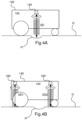
- Figure 4A shows a schematic view of an example embodiment of a robotic work tool, being a robotic lawnmower 100, according to the teachings herein.
- the robotic lawnmower 100 is travelling over an uneven surface, as indicated by the hole (referenced H) in the travelled surface, i.e. the ground G.
- the robotic lawnmower 100 may sense a distance SD that exceeds the threshold distance and then detect a false lift event.
- the robotic lawnmower 100 is in one embodiment configured to determine the sensed distance over a time period. For example by determining an average of the sensed distance for the time period such as by integrating the sensed distance over the time period time or summarizing the sensed distances for a series of echoes and dividing by the number of echoes.
- the time period is 0.5 sec, 0.25 sec, 0.2 sec, 0.15 sec, 0.1 sec or 0.05 sec.
- the robotic lawnmower is, in one embodiment configured to prevent such false lift event detections by utilizing more than one radar device 190.
- the robotic lawnmower 100 is arranged with two radar devices, a front radar device 190' and a rear radar device 190". It should be noted that other numbers of radar devices and arrangements of the radar devices 190 are also possible. One example being shown in figure 1B where four radar devices 190 are arranged. Another example being where three radar devices are arranged, either two at the front and one at the rear, or one at the front and two at the rear. Such arrangements are beneficially used for robotic lawnmowers with three wheels.
- Arrangements with more than one radar device 190 are thus configured to provide a plurality of sensed distances, one from each radar device.
- the robotic lawnmower 100 is configured to determine the sensed distance SD to the surface travelled G by determining a first sensed distance SD1 utilizing the front or first radar device 190'.
- the robotic lawnmower is also configured to determine a second sensed distance SD2 utilizing the rear or second radar device 190".
- the robotic lawnmower 100 is configured to determine the sensed distance SD based on the first sensed distance SD1 and the second sensed distance SD2.
- the robotic lawnmower 100 is configured to determine if a lift event is detected by comparing each sensed distance SD to the surface travelled G to each a threshold distance. Several situations may apply.
- a lift event is detected.
- the robotic lawnmower 100 is configured to determine that the lift event is detected, if also the radar devices on the opposite side provide sensed distances that have become shorter than the normative distance, i.e. falling below a second threshold. Which indicates that the robotic lawnmower is being tilted to one side.
- the sensed distance is determined as the average of the plurality of sensed distances, in the example of figure 4B , the average of the first and the second sensed distance. This enables for reducing the effect of uneven surfaces.
- the sensed distance is determined to be the minimum of the plurality of sensed distances. In the example of figure 4B , the lower of the first and the second sensed distances. This enables for reducing the risk of a false lift event.
- the radar device 190 As the emitted or transmitted radar pulse is intercepted by an object or surface, from here on a substrate, a portion of the energy of the radar pulse will be reflected in every direction, including the direction back to the radar device. The reflected pulse or echo will thus be received after a time t. As has been discussed in the above, this time corresponds to double the distance travelled. As most substrates that reflect the pulse or give rise to an echo are irregular, the echo will in most cases not be a short pulse, but rather an extended wave form.
- the radar device 190 is, in one embodiment, configured to determine if a pulse has been received at given times or time intervals.
- the times (or time intervals) correspond to expected distances to substrates.
- Figure 5A shows an example embodiment of how the radar device 190 determines the reception of an echo.
- Figure 5A shows a graph illustrating the received energy E over time t. Three time windows w1, w2 and w3 are also illustrated.
- the radar device 190 is, in one embodiment, configured to determine that an echo has been received within at least one time window w1, w2, w3.
- the different time windows correspond to expected distances that an echo could be expected to be reflected from.
- the time of reception ti corresponds to a distance Di.
- a distance Di that an echo is expected to be received from is the normative distance. In figure 5A this would correspond to the time window w2.
- Another example of a distance Di that an echo is expected to be received from is a series of distances around the threshold distance, or from the normative distance to the threshold distance, possibly going beyond the threshold distance. In figure 5A this would correspond to the time window w3.
- the robotic lawnmower 100 is configured to calibrate the radar device by receiving pulses in wider or more time windows and determine over time the most likely or rather most frequently times where an echo is received. The time window(s) can then be set to be closer to or narrower around the expected times.
- the robotic lawnmower 100 is configured in one embodiment, to repeatedly calibrate the time windows to accommodate any shifts. For shifts occurring slowly, the robotic lawnmower 100 may be configured to move a time window if it is determined that the expected echo is received closer to an edge of the time window, whereby the time window is moved so that the echo is received in a center area of the time window. For shifts occurring suddenly, the robotic lawnmower 100 may be configured to expand a time window or introduce more time windows around the time window if it is determined that an expected echo is not received. Especially if the echo is not received for a given number of times to allow for various errors and irregularities. The expanded or added time window(s) will then enable the robotic lawnmower 100 to recalibrate the time window(s) to the new expected time position of the expected echo.
- the robotic lawnmower 100 may also be calibrated in how often and for how long to calibrate the time windows. For a surface with many irregularities the normative distance may vary greatly and a more frequent calibration may be needed. Likewise a longer time window over which the normative distance is determined may be required. For smooth surfaces, a less frequent calibration will be needed. Likewise a shorter time window over which the normative distance is determined may be required.
- a portion of a radar pulse is reflected upon intercepting a substrate. How large this portion is depends on a number of factors such as the density and composition of the substrate. Different substrates will thus give rise to echoes having different energy content, i.e. they will be of different strength or amplitude.
- Figure 5B shows an example illustrating how different echoes from different substrates are received at different times, and at different energy levels.
- three external pulses are shown to be received in each a time window, a first echo e1 is received in a first time window w1, a second echo e2 is received in a second time window and a third echo e3 is possibly received in a third time window (as indicated by the dashed line).
- the first echo may correspond to the grass height, which will be more or less constant for a garden before being serviced, and at another constant level after having been serviced.
- the second echo e2 corresponds to the normative distance.
- the third echo e3 may correspond to a distance exceeding the threshold thereby indicating a lift event.
- an echo e0 without a corresponding time window is also shown.
- Such an echo may be the result of internal structures, such as the reflection from the body 140 of the robotic lawnmower 100 (or even from dirt or debris stuck to the underside of the body).
- time windows such echoes may be filtered out or ignored by not assigning a time window to its expected location.
- FIG. 5B showing four known echoes, this would entail a saving in processing power of 25%. It will also render the radar device less susceptible to noise and other interferences.
- the radar device 190 may be utilized to determine the height of the grass. As the ground will provide a stronger echo, i.e. a reflected pulse having a higher energy content or signal strength, than for example grass, utilizing the radar device 190 enables the robotic lawnmower 100 to also determine the height of the grass.
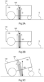
- Figure 6A shows a schematic view of an example embodiment of a robotic work tool, being a robotic lawnmower 100, according to the teachings herein.
- the robotic lawnmower 100 is travelling over a surface covered with grass.
- the radar device 190 receives two echoes, one from the grass layer and one from the ground G. It could be noted that the radar device 190 will also receive an echo from the body of the robotic lawnmower 100, which echo may be ignored.
- the robotic lawnmower 100 is configured to determine that the first external echo (as differentiated from internal echoes, being any echoes originating from inside the robotic lawnmower 100) indicates the level of the grass layer, and that the second echo indicates the ground level.
- the first distance being determined based on the first echo, thus represent the distance to the grass layer and the second distance, being determined based on the second echo, thus represent the distance to the ground level.
- Figure 6B shows an energy-time diagram where the energy content, i.e. signal strength, of the received echoes are shown against the time from transmission of the radar pulse.
- the robotic lawnmower 100 is configured to determine that the external echo (as differentiated from internal echoes, being any echoes originating from inside the robotic lawnmower 100) having the lowest energy content indicates the level of the grass layer, and that the echo having the highest energy content indicates the ground level.
- the first distance being determined based on the echo with the lowest energy content, thus represent the distance to the grass layer and the second distance, being determined based on the echo with the highest energy content, thus represent the distance to the ground level.
- the robotic lawnmower 100 is configured to determine that the external echo (as differentiated from internal echoes, being any echoes originating from inside the robotic lawnmower 100) having an energy content corresponding to a reflection from grass indicates the level of the grass layer, and that the echo having an energy content corresponding to a reflection from the ground level indicates the ground level.
- the grass height may be determined as the difference between the first distance and the second distance, or alternatively as the difference between the normative distance and the first distance.
- FIG. 7 shows a flowchart of a general method according to the teachings herein.
- the robotic lawnmower 100 determines 710 a sensed distance (SD) to a surface travelled (G) utilizing the at least one radar device (190, 190', 190").
- the robotic lawnmower 100 determines 720 whether the sensed distance is greater than a threshold distance; and if so detects 730 a lift event.
- the robotic lawnmower 100 is configured to determine the height of the grass by utilizing the radar device 190.
- FIG. 8 shows a flowchart of a general method according to the teachings herein
- the radar devices 190 may also be utilized to determine an effectiveness of the grass cutting by comparing the distance to the cut grass (grass behind cutter) with the distance to the uncut grass (grass in front of cutter). Even if this is not an exact measurement, it provides an indication of the effectiveness of the grass cutting and may enable for a better scheduling of the operation of the robotic lawnmower 100.
- the cutting tool 160 may also be adapted based on the detected height of grass.
- the cutting height of the cutting tool may be adapted.
- Another example is adapting the power delivered to the cutting tool.
- the same methodology may also be applied to other robotic services where the surface travelled provides a different radar echo (either in time received, strength or both) before and after having been serviced.
Landscapes
- Engineering & Computer Science (AREA)
- Remote Sensing (AREA)
- Radar, Positioning & Navigation (AREA)
- Physics & Mathematics (AREA)
- General Physics & Mathematics (AREA)
- Automation & Control Theory (AREA)
- Computer Networks & Wireless Communication (AREA)
- Environmental Sciences (AREA)
- Life Sciences & Earth Sciences (AREA)
- Electromagnetism (AREA)
- Aviation & Aerospace Engineering (AREA)
- Robotics (AREA)
- Control Of Position, Course, Altitude, Or Attitude Of Moving Bodies (AREA)
Claims (12)
- Roboterrasenmähersystem (200), umfassend einen Roboterrasenmäher (100), umfassend mindestens einen Abstandssensor (190), wobei der Abstandssensor (190) eine Radarvorrichtung (190, 190', 190") umfasst, wobei der Roboterrasenmäher (100) für Folgendes konfiguriert ist:Bestimmen eines erfassten Abstands (SD) zu einer befahrenen Oberfläche (G) unter Nutzung der mindestens einen Radarvorrichtung (190, 190', 190");Bestimmen, ob der erfasste Abstand größer als ein Schwellenwertabstand ist; und, falls ja,Erkennen eines Hebeereignisses.
- Roboterrasenmähersystem nach Anspruch 1, wobei die Radarvorrichtung auf die befahrene Oberfläche (G) gerichtet ist.
- Roboterrasenmähersystem nach einem vorhergehenden Anspruch, wobei der Körper (140) des Roboterrasenmähers ein in sich geschlossener Körper (140) ist, der ein Chassis (140-2) und eine äußere Abdeckung (140-1) umfasst, wobei das Chassis (140-2) und die äußere Abdeckung (140-1) so angeordnet sind, dass sie relativ zueinander nicht beweglich sind.
- Roboterrasenmähersystem nach einem vorhergehenden Anspruch, wobei der Roboterrasenmäher ferner konfiguriert ist, um den Schwellenwertabstand während eines Zeitabschnitts zu bestimmen.
- Roboterrasenmähersystem nach einem vorhergehenden Anspruch, wobei der Roboterrasenmäher (100) einen ersten Abstandssensor (190') und einen zweiten Abstandssensor (190") umfasst, wobei die Steuerung (110) ferner konfiguriert ist, um den erfassten Abstand (SD) zu der befahrenen Oberfläche (G) durch Folgendes zu bestimmen:Bestimmen eines ersten erfassten Abstands (SD1) unter Nutzung des ersten Abstandssensors (190');Bestimmen eines zweiten erfassten Abstands (SD2) unter Nutzung des zweiten Abstandssensors (190''); undBestimmen des erfassten Abstands (SD) basierend auf dem ersten erfassten Abstand (SD1) und dem zweiten erfassten Abstand (SD2).
- Roboterrasenmähersystem nach Anspruch 5, wobei der erste Abstandssensor eine erste Radarvorrichtung (190') ist und der Abstandssensor eine zweite Radarvorrichtung (190") ist und wobei die Steuerung (110) ferner für Folgendes konfiguriert ist:Bestimmen des ersten erfassten Abstands (SD1) unter Nutzung der ersten Radarvorrichtung (190');Bestimmen des zweiten erfassten Abstands (SD2) unter Nutzung der zweiten Radarvorrichtung (190''); undBestimmen des erfassten Abstands (SD) basierend auf dem ersten erfassten Abstand (SD1) und dem zweiten erfassten Abstand (SD2).
- Roboterrasenmähersystem nach einem vorhergehenden Anspruch, wobei der Roboterrasenmäher ferner konfiguriert ist, um ein Radarecho innerhalb eines Zeitfensters (w1, w2, w3) zu empfangen.
- Roboterrasenmähersystem nach Anspruch 7, wobei der Roboterrasenmäher ferner konfiguriert ist, um mindestens auf Zeitfenster (w1, w2, w3) zu rekalibrieren.
- Roboterrasenmähersystem nach einem der Ansprüche 1 bis 8, wobei der Roboterrasenmäher ferner konfiguriert ist, um den Energieinhalt eines empfangenen Radarechos zu bestimmen und ein Reflexionssubstrat basierend auf dem bestimmten Energieinhalt des empfangenen Radarechos zu bestimmen.
- Roboterrasenmähersystem nach einem der Ansprüche 1 bis 9, wobei der Roboterrasenmäher ferner konfiguriert ist, um einen Abstand zu einem Reflexionssubstrat basierend auf der Zeit des Empfangs eines empfangenen Radarechos zu bestimmen.
- Roboterrasenmähersystem nach Anspruch 10, wobei der Roboterrasenmäher ferner konfiguriert ist, um die Höhe von Gras basierend auf der Zeit des Empfangs eines empfangenen Radarechos zu bestimmen.
- Verfahren zur Verwendung in einem Roboterrasenmähersystem (200), umfassend einen Roboterrasenmäher (100), umfassend einen Abstandssensor (190), wobei der Abstandssensor eine Radarvorrichtung (190, 190', 190") ist, wobei das Verfahren Folgendes umfasst:Bestimmen eines erfassten Abstands (SD) zu einer befahrenen Oberfläche (G) unter Nutzung der mindestens einen Radarvorrichtung (190, 190', 190");Bestimmen, ob der erfasste Abstand größer als ein Schwellenwertabstand ist; und, falls ja,Erkennen eines Hebeereignisses.
Applications Claiming Priority (2)
| Application Number | Priority Date | Filing Date | Title |
|---|---|---|---|
| SE1950044A SE543246C2 (en) | 2019-01-15 | 2019-01-15 | Robotic lawn mower system for detecting a lift event and method for use in a lawn mower system |
| PCT/EP2020/050480 WO2020148168A1 (en) | 2019-01-15 | 2020-01-10 | Improved lift detection for a robotic work tool |
Publications (2)
| Publication Number | Publication Date |
|---|---|
| EP3911973A1 EP3911973A1 (de) | 2021-11-24 |
| EP3911973B1 true EP3911973B1 (de) | 2023-10-18 |
Family
ID=69165367
Family Applications (1)
| Application Number | Title | Priority Date | Filing Date |
|---|---|---|---|
| EP20700673.5A Active EP3911973B1 (de) | 2019-01-15 | 2020-01-10 | Verbesserte kollisionsdetektion für ein roboterarbeitswerkzeug |
Country Status (4)
| Country | Link |
|---|---|
| US (1) | US20220022371A1 (de) |
| EP (1) | EP3911973B1 (de) |
| SE (1) | SE543246C2 (de) |
| WO (1) | WO2020148168A1 (de) |
Families Citing this family (12)
| Publication number | Priority date | Publication date | Assignee | Title |
|---|---|---|---|---|
| CN109772841B (zh) * | 2019-01-23 | 2021-09-03 | 合肥仁洁智能科技有限公司 | 一种光伏组件清扫机器人及其越障控制方法和装置 |
| KR20220025605A (ko) * | 2020-08-24 | 2022-03-03 | 엘지전자 주식회사 | 이동 로봇 및 이의 제어 방법 |
| CN114616973B (zh) * | 2020-12-11 | 2023-10-10 | 苏州宝时得电动工具有限公司 | 割草机和割草机的控制方法 |
| US12296694B2 (en) | 2021-03-10 | 2025-05-13 | Techtronic Cordless Gp | Lawnmowers |
| SE545768C2 (en) * | 2021-09-14 | 2024-01-09 | Husqvarna Ab | Robotic lawnmower system configured to adapt scheduling based on weeds determination |
| US12443180B2 (en) | 2021-11-10 | 2025-10-14 | Techtronic Cordless Gp | Robotic lawn mowers |
| AU2023200381A1 (en) | 2022-01-31 | 2023-08-17 | Techtronic Cordless Gp | Robotic garden tool |
| EP4270138A1 (de) | 2022-04-28 | 2023-11-01 | Techtronic Cordless GP | Erzeugung einer virtuellen grenze für ein robotisches gartenwerkzeug |
| US12472611B2 (en) | 2022-05-31 | 2025-11-18 | Techtronic Cordless Gp | Peg driver |
| AU2023204696A1 (en) | 2022-07-19 | 2024-02-08 | Techtronic Cordless Gp | Display for controlling robotic tool |
| AU2023206123A1 (en) | 2022-07-29 | 2024-02-15 | Techtronic Cordless Gp | Generation of a cryptography key for a robotic garden tool |
| SE2350862A1 (en) * | 2023-07-06 | 2025-01-07 | Husqvarna Ab | Robotic work tool |
Family Cites Families (4)
| Publication number | Priority date | Publication date | Assignee | Title |
|---|---|---|---|---|
| KR100657530B1 (ko) * | 2005-03-31 | 2006-12-14 | 엘지전자 주식회사 | 자동주행 로봇의 들림감지장치 |
| US7304601B1 (en) * | 2006-09-07 | 2007-12-04 | Rosemount Tank Radar Ab | Device and a method for accurate radar level gauging |
| SE540585C2 (en) * | 2017-03-23 | 2018-10-02 | Husqvarna Ab | A robotic work tool and a method for use in a robotic work tool comprising a lift/collision detection device |
| US10980173B2 (en) * | 2017-09-13 | 2021-04-20 | Black & Decker Inc. | Riding mower with removeable battery module |
-
2019
- 2019-01-15 SE SE1950044A patent/SE543246C2/en unknown
-
2020
- 2020-01-10 EP EP20700673.5A patent/EP3911973B1/de active Active
- 2020-01-10 WO PCT/EP2020/050480 patent/WO2020148168A1/en not_active Ceased
- 2020-01-10 US US17/296,413 patent/US20220022371A1/en not_active Abandoned
Also Published As
| Publication number | Publication date |
|---|---|
| US20220022371A1 (en) | 2022-01-27 |
| SE543246C2 (en) | 2020-10-27 |
| SE1950044A1 (en) | 2020-07-16 |
| WO2020148168A1 (en) | 2020-07-23 |
| EP3911973A1 (de) | 2021-11-24 |
Similar Documents
| Publication | Publication Date | Title |
|---|---|---|
| EP3911973B1 (de) | Verbesserte kollisionsdetektion für ein roboterarbeitswerkzeug | |
| EP4118509B1 (de) | System und verfahren zur verbesserten navigation eines roboterarbeitswerkzeugs | |
| US20240077885A1 (en) | Automatic working system, self-moving device, and methods for controlling same | |
| SE1950046A1 (en) | Robotic work tool system for detecting a lift event and method for use in a robotic work tool system | |
| EP3829832B1 (de) | Sich bewegender roboter, sich bewegendes robotersystem und verfahren zum bewegen eines sich bewegenden roboters zur ladestation | |
| EP4133349B1 (de) | Verbesserte navigation für ein robotisches arbeitswerkzeug | |
| EP3236733B1 (de) | Verbesserte navigation für einen robotischen rasenmäher | |
| US10928833B2 (en) | Navigation for a robotic work tool | |
| TWI439834B (zh) | 移動平台之導航方法與系統 | |
| EP4072261B1 (de) | Austrittswegbestimmung für ein roboterwerkzeug | |
| EP3953783B1 (de) | System und verfahren zum signalempfang für ein robotisches arbeitswerkzeug | |
| US20180364735A1 (en) | Improved navigation for a vehicle by implementing two operating modes | |
| US11169530B1 (en) | Outdoor robotic work tool comprising an environmental detection system | |
| WO2015072896A1 (en) | Improved navigation for a robotic working tool | |
| SE543019C2 (en) | Improving the navigation of robotic lawnmower by determining that a navigational beacon has moved based on the position of the robotic lawnmower | |
| EP3919237B1 (de) | Mobiler roboter und steuerungsverfahren dafür | |
| CN112835361A (zh) | 清扫车沿边作业方法 |
Legal Events
| Date | Code | Title | Description |
|---|---|---|---|
| STAA | Information on the status of an ep patent application or granted ep patent |
Free format text: STATUS: UNKNOWN |
|
| STAA | Information on the status of an ep patent application or granted ep patent |
Free format text: STATUS: THE INTERNATIONAL PUBLICATION HAS BEEN MADE |
|
| PUAI | Public reference made under article 153(3) epc to a published international application that has entered the european phase |
Free format text: ORIGINAL CODE: 0009012 |
|
| STAA | Information on the status of an ep patent application or granted ep patent |
Free format text: STATUS: REQUEST FOR EXAMINATION WAS MADE |
|
| 17P | Request for examination filed |
Effective date: 20210715 |
|
| AK | Designated contracting states |
Kind code of ref document: A1 Designated state(s): AL AT BE BG CH CY CZ DE DK EE ES FI FR GB GR HR HU IE IS IT LI LT LU LV MC MK MT NL NO PL PT RO RS SE SI SK SM TR |
|
| R17P | Request for examination filed (corrected) |
Effective date: 20210715 |
|
| DAV | Request for validation of the european patent (deleted) | ||
| DAX | Request for extension of the european patent (deleted) | ||
| GRAP | Despatch of communication of intention to grant a patent |
Free format text: ORIGINAL CODE: EPIDOSNIGR1 |
|
| STAA | Information on the status of an ep patent application or granted ep patent |
Free format text: STATUS: GRANT OF PATENT IS INTENDED |
|
| GRAS | Grant fee paid |
Free format text: ORIGINAL CODE: EPIDOSNIGR3 |
|
| INTG | Intention to grant announced |
Effective date: 20230817 |
|
| GRAA | (expected) grant |
Free format text: ORIGINAL CODE: 0009210 |
|
| STAA | Information on the status of an ep patent application or granted ep patent |
Free format text: STATUS: THE PATENT HAS BEEN GRANTED |
|
| P01 | Opt-out of the competence of the unified patent court (upc) registered |
Effective date: 20230824 |
|
| AK | Designated contracting states |
Kind code of ref document: B1 Designated state(s): AL AT BE BG CH CY CZ DE DK EE ES FI FR GB GR HR HU IE IS IT LI LT LU LV MC MK MT NL NO PL PT RO RS SE SI SK SM TR |
|
| REG | Reference to a national code |
Ref country code: GB Ref legal event code: FG4D |
|
| REG | Reference to a national code |
Ref country code: CH Ref legal event code: EP |
|
| REG | Reference to a national code |
Ref country code: IE Ref legal event code: FG4D |
|
| REG | Reference to a national code |
Ref country code: DE Ref legal event code: R096 Ref document number: 602020019411 Country of ref document: DE |
|
| REG | Reference to a national code |
Ref country code: LT Ref legal event code: MG9D |
|
| REG | Reference to a national code |
Ref country code: NL Ref legal event code: MP Effective date: 20231018 |
|
| REG | Reference to a national code |
Ref country code: AT Ref legal event code: MK05 Ref document number: 1622916 Country of ref document: AT Kind code of ref document: T Effective date: 20231018 |
|
| PG25 | Lapsed in a contracting state [announced via postgrant information from national office to epo] |
Ref country code: NL Free format text: LAPSE BECAUSE OF FAILURE TO SUBMIT A TRANSLATION OF THE DESCRIPTION OR TO PAY THE FEE WITHIN THE PRESCRIBED TIME-LIMIT Effective date: 20231018 |
|
| PG25 | Lapsed in a contracting state [announced via postgrant information from national office to epo] |
Ref country code: GR Free format text: LAPSE BECAUSE OF FAILURE TO SUBMIT A TRANSLATION OF THE DESCRIPTION OR TO PAY THE FEE WITHIN THE PRESCRIBED TIME-LIMIT Effective date: 20240119 |
|
| PG25 | Lapsed in a contracting state [announced via postgrant information from national office to epo] |
Ref country code: IS Free format text: LAPSE BECAUSE OF FAILURE TO SUBMIT A TRANSLATION OF THE DESCRIPTION OR TO PAY THE FEE WITHIN THE PRESCRIBED TIME-LIMIT Effective date: 20240218 |
|
| PG25 | Lapsed in a contracting state [announced via postgrant information from national office to epo] |
Ref country code: LT Free format text: LAPSE BECAUSE OF FAILURE TO SUBMIT A TRANSLATION OF THE DESCRIPTION OR TO PAY THE FEE WITHIN THE PRESCRIBED TIME-LIMIT Effective date: 20231018 |
|
| PG25 | Lapsed in a contracting state [announced via postgrant information from national office to epo] |
Ref country code: AT Free format text: LAPSE BECAUSE OF FAILURE TO SUBMIT A TRANSLATION OF THE DESCRIPTION OR TO PAY THE FEE WITHIN THE PRESCRIBED TIME-LIMIT Effective date: 20231018 |
|
| PG25 | Lapsed in a contracting state [announced via postgrant information from national office to epo] |
Ref country code: ES Free format text: LAPSE BECAUSE OF FAILURE TO SUBMIT A TRANSLATION OF THE DESCRIPTION OR TO PAY THE FEE WITHIN THE PRESCRIBED TIME-LIMIT Effective date: 20231018 |
|
| PG25 | Lapsed in a contracting state [announced via postgrant information from national office to epo] |
Ref country code: LT Free format text: LAPSE BECAUSE OF FAILURE TO SUBMIT A TRANSLATION OF THE DESCRIPTION OR TO PAY THE FEE WITHIN THE PRESCRIBED TIME-LIMIT Effective date: 20231018 Ref country code: IS Free format text: LAPSE BECAUSE OF FAILURE TO SUBMIT A TRANSLATION OF THE DESCRIPTION OR TO PAY THE FEE WITHIN THE PRESCRIBED TIME-LIMIT Effective date: 20240218 Ref country code: GR Free format text: LAPSE BECAUSE OF FAILURE TO SUBMIT A TRANSLATION OF THE DESCRIPTION OR TO PAY THE FEE WITHIN THE PRESCRIBED TIME-LIMIT Effective date: 20240119 Ref country code: ES Free format text: LAPSE BECAUSE OF FAILURE TO SUBMIT A TRANSLATION OF THE DESCRIPTION OR TO PAY THE FEE WITHIN THE PRESCRIBED TIME-LIMIT Effective date: 20231018 Ref country code: BG Free format text: LAPSE BECAUSE OF FAILURE TO SUBMIT A TRANSLATION OF THE DESCRIPTION OR TO PAY THE FEE WITHIN THE PRESCRIBED TIME-LIMIT Effective date: 20240118 Ref country code: AT Free format text: LAPSE BECAUSE OF FAILURE TO SUBMIT A TRANSLATION OF THE DESCRIPTION OR TO PAY THE FEE WITHIN THE PRESCRIBED TIME-LIMIT Effective date: 20231018 Ref country code: PT Free format text: LAPSE BECAUSE OF FAILURE TO SUBMIT A TRANSLATION OF THE DESCRIPTION OR TO PAY THE FEE WITHIN THE PRESCRIBED TIME-LIMIT Effective date: 20240219 |
|
| PG25 | Lapsed in a contracting state [announced via postgrant information from national office to epo] |
Ref country code: SE Free format text: LAPSE BECAUSE OF FAILURE TO SUBMIT A TRANSLATION OF THE DESCRIPTION OR TO PAY THE FEE WITHIN THE PRESCRIBED TIME-LIMIT Effective date: 20231018 Ref country code: RS Free format text: LAPSE BECAUSE OF FAILURE TO SUBMIT A TRANSLATION OF THE DESCRIPTION OR TO PAY THE FEE WITHIN THE PRESCRIBED TIME-LIMIT Effective date: 20231018 Ref country code: PL Free format text: LAPSE BECAUSE OF FAILURE TO SUBMIT A TRANSLATION OF THE DESCRIPTION OR TO PAY THE FEE WITHIN THE PRESCRIBED TIME-LIMIT Effective date: 20231018 Ref country code: NO Free format text: LAPSE BECAUSE OF FAILURE TO SUBMIT A TRANSLATION OF THE DESCRIPTION OR TO PAY THE FEE WITHIN THE PRESCRIBED TIME-LIMIT Effective date: 20240118 Ref country code: LV Free format text: LAPSE BECAUSE OF FAILURE TO SUBMIT A TRANSLATION OF THE DESCRIPTION OR TO PAY THE FEE WITHIN THE PRESCRIBED TIME-LIMIT Effective date: 20231018 Ref country code: HR Free format text: LAPSE BECAUSE OF FAILURE TO SUBMIT A TRANSLATION OF THE DESCRIPTION OR TO PAY THE FEE WITHIN THE PRESCRIBED TIME-LIMIT Effective date: 20231018 |
|
| PG25 | Lapsed in a contracting state [announced via postgrant information from national office to epo] |
Ref country code: DK Free format text: LAPSE BECAUSE OF FAILURE TO SUBMIT A TRANSLATION OF THE DESCRIPTION OR TO PAY THE FEE WITHIN THE PRESCRIBED TIME-LIMIT Effective date: 20231018 |
|
| REG | Reference to a national code |
Ref country code: DE Ref legal event code: R097 Ref document number: 602020019411 Country of ref document: DE |
|
| PG25 | Lapsed in a contracting state [announced via postgrant information from national office to epo] |
Ref country code: CZ Free format text: LAPSE BECAUSE OF FAILURE TO SUBMIT A TRANSLATION OF THE DESCRIPTION OR TO PAY THE FEE WITHIN THE PRESCRIBED TIME-LIMIT Effective date: 20231018 |
|
| PG25 | Lapsed in a contracting state [announced via postgrant information from national office to epo] |
Ref country code: SK Free format text: LAPSE BECAUSE OF FAILURE TO SUBMIT A TRANSLATION OF THE DESCRIPTION OR TO PAY THE FEE WITHIN THE PRESCRIBED TIME-LIMIT Effective date: 20231018 |
|
| PG25 | Lapsed in a contracting state [announced via postgrant information from national office to epo] |
Ref country code: SM Free format text: LAPSE BECAUSE OF FAILURE TO SUBMIT A TRANSLATION OF THE DESCRIPTION OR TO PAY THE FEE WITHIN THE PRESCRIBED TIME-LIMIT Effective date: 20231018 Ref country code: SK Free format text: LAPSE BECAUSE OF FAILURE TO SUBMIT A TRANSLATION OF THE DESCRIPTION OR TO PAY THE FEE WITHIN THE PRESCRIBED TIME-LIMIT Effective date: 20231018 Ref country code: RO Free format text: LAPSE BECAUSE OF FAILURE TO SUBMIT A TRANSLATION OF THE DESCRIPTION OR TO PAY THE FEE WITHIN THE PRESCRIBED TIME-LIMIT Effective date: 20231018 Ref country code: IT Free format text: LAPSE BECAUSE OF FAILURE TO SUBMIT A TRANSLATION OF THE DESCRIPTION OR TO PAY THE FEE WITHIN THE PRESCRIBED TIME-LIMIT Effective date: 20231018 Ref country code: EE Free format text: LAPSE BECAUSE OF FAILURE TO SUBMIT A TRANSLATION OF THE DESCRIPTION OR TO PAY THE FEE WITHIN THE PRESCRIBED TIME-LIMIT Effective date: 20231018 Ref country code: DK Free format text: LAPSE BECAUSE OF FAILURE TO SUBMIT A TRANSLATION OF THE DESCRIPTION OR TO PAY THE FEE WITHIN THE PRESCRIBED TIME-LIMIT Effective date: 20231018 Ref country code: CZ Free format text: LAPSE BECAUSE OF FAILURE TO SUBMIT A TRANSLATION OF THE DESCRIPTION OR TO PAY THE FEE WITHIN THE PRESCRIBED TIME-LIMIT Effective date: 20231018 |
|
| PLBE | No opposition filed within time limit |
Free format text: ORIGINAL CODE: 0009261 |
|
| STAA | Information on the status of an ep patent application or granted ep patent |
Free format text: STATUS: NO OPPOSITION FILED WITHIN TIME LIMIT |
|
| PG25 | Lapsed in a contracting state [announced via postgrant information from national office to epo] |
Ref country code: MC Free format text: LAPSE BECAUSE OF FAILURE TO SUBMIT A TRANSLATION OF THE DESCRIPTION OR TO PAY THE FEE WITHIN THE PRESCRIBED TIME-LIMIT Effective date: 20231018 |
|
| PG25 | Lapsed in a contracting state [announced via postgrant information from national office to epo] |
Ref country code: MC Free format text: LAPSE BECAUSE OF FAILURE TO SUBMIT A TRANSLATION OF THE DESCRIPTION OR TO PAY THE FEE WITHIN THE PRESCRIBED TIME-LIMIT Effective date: 20231018 |
|
| REG | Reference to a national code |
Ref country code: CH Ref legal event code: PL |
|
| PG25 | Lapsed in a contracting state [announced via postgrant information from national office to epo] |
Ref country code: LU Free format text: LAPSE BECAUSE OF NON-PAYMENT OF DUE FEES Effective date: 20240110 |
|
| 26N | No opposition filed |
Effective date: 20240719 |
|
| PG25 | Lapsed in a contracting state [announced via postgrant information from national office to epo] |
Ref country code: LU Free format text: LAPSE BECAUSE OF NON-PAYMENT OF DUE FEES Effective date: 20240110 |
|
| PG25 | Lapsed in a contracting state [announced via postgrant information from national office to epo] |
Ref country code: BE Free format text: LAPSE BECAUSE OF NON-PAYMENT OF DUE FEES Effective date: 20240131 |
|
| PG25 | Lapsed in a contracting state [announced via postgrant information from national office to epo] |
Ref country code: CH Free format text: LAPSE BECAUSE OF NON-PAYMENT OF DUE FEES Effective date: 20240131 |
|
| PG25 | Lapsed in a contracting state [announced via postgrant information from national office to epo] |
Ref country code: SI Free format text: LAPSE BECAUSE OF FAILURE TO SUBMIT A TRANSLATION OF THE DESCRIPTION OR TO PAY THE FEE WITHIN THE PRESCRIBED TIME-LIMIT Effective date: 20231018 |
|
| PG25 | Lapsed in a contracting state [announced via postgrant information from national office to epo] |
Ref country code: SI Free format text: LAPSE BECAUSE OF FAILURE TO SUBMIT A TRANSLATION OF THE DESCRIPTION OR TO PAY THE FEE WITHIN THE PRESCRIBED TIME-LIMIT Effective date: 20231018 Ref country code: CH Free format text: LAPSE BECAUSE OF NON-PAYMENT OF DUE FEES Effective date: 20240131 Ref country code: BE Free format text: LAPSE BECAUSE OF NON-PAYMENT OF DUE FEES Effective date: 20240131 |
|
| REG | Reference to a national code |
Ref country code: BE Ref legal event code: MM Effective date: 20240131 |
|
| PGFP | Annual fee paid to national office [announced via postgrant information from national office to epo] |
Ref country code: GB Payment date: 20241213 Year of fee payment: 6 |
|
| PG25 | Lapsed in a contracting state [announced via postgrant information from national office to epo] |
Ref country code: IE Free format text: LAPSE BECAUSE OF NON-PAYMENT OF DUE FEES Effective date: 20240110 |
|
| PG25 | Lapsed in a contracting state [announced via postgrant information from national office to epo] |
Ref country code: IE Free format text: LAPSE BECAUSE OF NON-PAYMENT OF DUE FEES Effective date: 20240110 |
|
| PG25 | Lapsed in a contracting state [announced via postgrant information from national office to epo] |
Ref country code: CY Free format text: LAPSE BECAUSE OF FAILURE TO SUBMIT A TRANSLATION OF THE DESCRIPTION OR TO PAY THE FEE WITHIN THE PRESCRIBED TIME-LIMIT; INVALID AB INITIO Effective date: 20200110 |
|
| PG25 | Lapsed in a contracting state [announced via postgrant information from national office to epo] |
Ref country code: HU Free format text: LAPSE BECAUSE OF FAILURE TO SUBMIT A TRANSLATION OF THE DESCRIPTION OR TO PAY THE FEE WITHIN THE PRESCRIBED TIME-LIMIT; INVALID AB INITIO Effective date: 20200110 |
|
| PG25 | Lapsed in a contracting state [announced via postgrant information from national office to epo] |
Ref country code: FI Free format text: LAPSE BECAUSE OF FAILURE TO SUBMIT A TRANSLATION OF THE DESCRIPTION OR TO PAY THE FEE WITHIN THE PRESCRIBED TIME-LIMIT Effective date: 20231019 |
|
| PG25 | Lapsed in a contracting state [announced via postgrant information from national office to epo] |
Ref country code: TR Free format text: LAPSE BECAUSE OF FAILURE TO SUBMIT A TRANSLATION OF THE DESCRIPTION OR TO PAY THE FEE WITHIN THE PRESCRIBED TIME-LIMIT Effective date: 20231018 |
|
| PGFP | Annual fee paid to national office [announced via postgrant information from national office to epo] |
Ref country code: FR Payment date: 20251210 Year of fee payment: 7 |
|
| PGFP | Annual fee paid to national office [announced via postgrant information from national office to epo] |
Ref country code: DE Payment date: 20251209 Year of fee payment: 7 |