EP3910312A1 - Sample dispersing device and sample dispersing method - Google Patents
Sample dispersing device and sample dispersing method Download PDFInfo
- Publication number
- EP3910312A1 EP3910312A1 EP21173848.9A EP21173848A EP3910312A1 EP 3910312 A1 EP3910312 A1 EP 3910312A1 EP 21173848 A EP21173848 A EP 21173848A EP 3910312 A1 EP3910312 A1 EP 3910312A1
- Authority
- EP
- European Patent Office
- Prior art keywords
- container
- wall portion
- sample
- powder sample
- covering member
- Prior art date
- Legal status (The legal status is an assumption and is not a legal conclusion. Google has not performed a legal analysis and makes no representation as to the accuracy of the status listed.)
- Granted
Links
Images



Classifications
-
- G—PHYSICS
- G01—MEASURING; TESTING
- G01N—INVESTIGATING OR ANALYSING MATERIALS BY DETERMINING THEIR CHEMICAL OR PHYSICAL PROPERTIES
- G01N1/00—Sampling; Preparing specimens for investigation
- G01N1/28—Preparing specimens for investigation including physical details of (bio-)chemical methods covered elsewhere, e.g. G01N33/50, C12Q
- G01N1/286—Preparing specimens for investigation including physical details of (bio-)chemical methods covered elsewhere, e.g. G01N33/50, C12Q involving mechanical work, e.g. chopping, disintegrating, compacting, homogenising
-
- G—PHYSICS
- G01—MEASURING; TESTING
- G01N—INVESTIGATING OR ANALYSING MATERIALS BY DETERMINING THEIR CHEMICAL OR PHYSICAL PROPERTIES
- G01N1/00—Sampling; Preparing specimens for investigation
- G01N1/28—Preparing specimens for investigation including physical details of (bio-)chemical methods covered elsewhere, e.g. G01N33/50, C12Q
- G01N1/2813—Producing thin layers of samples on a substrate, e.g. smearing, spinning-on
-
- G—PHYSICS
- G01—MEASURING; TESTING
- G01N—INVESTIGATING OR ANALYSING MATERIALS BY DETERMINING THEIR CHEMICAL OR PHYSICAL PROPERTIES
- G01N1/00—Sampling; Preparing specimens for investigation
- G01N1/28—Preparing specimens for investigation including physical details of (bio-)chemical methods covered elsewhere, e.g. G01N33/50, C12Q
-
- G—PHYSICS
- G01—MEASURING; TESTING
- G01N—INVESTIGATING OR ANALYSING MATERIALS BY DETERMINING THEIR CHEMICAL OR PHYSICAL PROPERTIES
- G01N1/00—Sampling; Preparing specimens for investigation
- G01N1/28—Preparing specimens for investigation including physical details of (bio-)chemical methods covered elsewhere, e.g. G01N33/50, C12Q
- G01N1/38—Diluting, dispersing or mixing samples
-
- G—PHYSICS
- G01—MEASURING; TESTING
- G01N—INVESTIGATING OR ANALYSING MATERIALS BY DETERMINING THEIR CHEMICAL OR PHYSICAL PROPERTIES
- G01N2203/00—Investigating strength properties of solid materials by application of mechanical stress
- G01N2203/02—Details not specific for a particular testing method
- G01N2203/026—Specifications of the specimen
- G01N2203/0284—Bulk material, e.g. powders
Definitions
- the present claimed invention relates to a sample dispersing device and a sample dispersing method for dispersing a powder sample on an analytical member.
- a sample is prepared by dispersing the powder sample on an upper surface of an analytical member.
- a sampler dispersing device that introduces a powder sample into a container that houses a holding member (an analytical member) such as a glass plate and that attaches the powder sample dispersed in the container to the holding member.
- Patent document 1 International Publication No. 2019 / 050035
- the present claimed invention was made in consideration of the above-mentioned problems, and a main object of this invention is to shorten cleaning time of a container in a sample dispersing device and to reduce variations of the cleaning state.
- the sample dispersing device in accordance with this invention is a sample dispersing device for dispersing a powder sample on an upper surface of an analytical member, and is characterized by comprising a container that has a placing surface on which the analytical member is placed, an introducing mechanism that is arranged in the container and that introduces the powder sample into inside of the container, and a covering member that covers an inner surface of the container and that can be attached to and removed from the container.
- the covering member that covers the inner surface of the container is removable from the container, it is possible to easily clean the container by replacing the covering member after use. As a result of this, it is possible to shorten the cleaning time of the container of the sample dispersing device, and to efficiently prepare samples with powder samples dispersed on the analytical member.
- a part covered by the covering member can be cleaned by replacing the covering member, it is possible to reduce the variation of the cleaning condition. Furthermore, since the cleaning can be conducted efficiently and without variation, it is possible to reduce the risk of confusion with other powder samples. In addition, it is also possible to reduce the risk of damage to the container during cleaning.
- the container has a lower wall portion having the placing surface on its upper surface, an upper wall portion facing the lower wall portion, and a side wall portion connecting the lower wall portion and the upper wall portion and surrounding the placing surface.
- a ratio of the inner surface of the side wall portion to the inner surface of the container becomes relatively large. For this reason, in order to make the effect of providing the covering member in a detachable manner remarkably, it is preferable that the covering member covers at least an inner surface of the side wall portion.
- the container is configured so that at least the lower wall portion is separable from the side wall portion.
- the covering member is made of an elastic body having a sheet shape and covers the inner surface of the side wall portion by being arranged in an elastically deformed state inside of the side wall portion.
- the covering member is fixed in contact with the inner surface of the side wall portion by the elastic resilience of the covering member by elastically deforming the covering member into a cylindrical shape and placing it inside the side wall portion, it is possible to eliminate the need for a separate fixing mechanism for fixing the covering member. In addition, it is possible to facilitate the replacing work of the covering member.
- the covering member is made of a material having light transmittance.
- the introducing mechanism introduces a gas containing the powder sample into the container by means of a pressure difference between the inside and the outside of the container and has an introducing pipe through which the gas containing the powder sample flows and which is provided with a plurality of narrowed portions, and one or more mesh members arranged in the introducing pipe.
- the mesh members are provided in the introducing tube, it is possible to subdivide the powder sample introduced into the container so that the powder sample can be efficiently dispersed inside of the container.
- a sample dispersing method in accordance with this invention is a sample dispersing method using a sample dispersing device that has a container having a placing surface on which an analytical member is placed and an introducing mechanism that introduces a powder sample into the container, and is characterized by that the powder sample is introduced into the container by the introducing mechanism and dispersed on an upper surface of the analytical member in a state wherein an inner surface of the container is covered by a covering member that can be attached to and removed from the container.
- the cleaning time of the container of the sample dispersing device can be shortened and the variation of the cleaning condition can be reduced.
- a sample dispersing device 100 in accordance with one embodiment of the present claimed invention will be described below with reference to drawings.
- the sample dispersing device 100 of this embodiment is to disperse a powder sample (W) on an upper surface of an analytical plate 10 as being an analytical member.
- the analytical plate 10 in this embodiment is a plate having a flat surface on its top.
- the analytical member is not limited to a plate-shaped plate, and various types of plates can be used according to the analytical device such as a microscope.
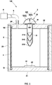
- the sample dispersing device 100 has a container 2 having a placing surface on which the analytical plate 10 is placed, an introducing mechanism 3 that is arranged in the container 2 and that introduces the powder sample (W) into inside of the container 2, and a covering member 4 that covers the inner surface of the container 2 and that is removable from the container 2.
- the container 2 has a lower wall portion 21 having a placing surface 2x on its upper surface, an upper wall portion 22 facing the lower wall portion 21, and a side wall portion 23 connected to the lower wall portion 21 and the upper wall portion 22 and surrounding the placing surface 2x.
- the lower wall portion 21 has a placing surface 2x on which the analytical plate 10 is placed and the placing surface 2x is set, for example, in a center of the lower wall portion 21.
- a placing stand on which the analytical plate 10 is placed is arranged in a center of the lower wall portion 21, and the upper surface of the placing stand may be used as the placing surface 2x.
- the upper wall portion 22 is provided with an introducing mechanism 3 and the introducing mechanism 3 is arranged, for example, in a center portion of the upper wall portion 22.
- the upper wall portion 22 is provided with an exhaust port 2P to make the inside of the container 2 in vacuum, and the exhaust port 2P is connected to a pressure reducing pump 6 through piping 5.
- the pressure in the inside of the container 2 is reduced to a predetermined vacuum level by the pressure reducing pump 6.
- the upper wall portion 22 may be provided with an atmospheric opening port to open the inside of the container 2 to the atmosphere.
- the side wall portion 23 has a cylindrical shape arranged between the lower wall portion 21 and the upper wall portion 22, and its lower end opening portion is closed by the lower wall portion 21 and its upper end opening portion is closed by the upper wall portion 22.
- the side wall portion 23 of this embodiment is made of a material having light transmittance (for example, quartz glass, acrylic glass, etc.) so that the interior part can be seen.
- the side wall portion 23 of this embodiment has a cylindrical shape.
- the container 2 is configured so that at least the lower wall portion 21 can be separated from the side wall portion 23.
- the upper wall portion 22 is configured to be separable from the side wall portion 23.
- the space between the side wall portion 23 and the lower wall portion 21 is made airtight through a sealing member S1 such as an O-ring, and the space between the side wall portion 23 and the upper wall portion 22 is also made airtight through a sealing member S2 such as an O-ring.
- the introducing mechanism 3 introduces a gas containing the powder sample (W) into the container 2 by means of a pressure difference between the inside and the outside of the container 2.
- the introducing mechanism 3 comprises an introducing tube 31 through which the gas containing the powder sample (W) flows and a supplying portion 32 that supplies the powder sample (W) to the introducing tube 31.
- the introducing tube 31 is arranged along the vertical direction while penetrating the upper wall portion 22 of the container 2.
- the introducing tube 31 is provided with a plurality of narrowed portions 31S between an upper end opening and a lower end opening of the introducing tube 31.
- the supplying portion 32 is arranged at the upper end opening of the introducing tube 31.
- the supplying portion 32 comprises a partition membrane 321 that blocks the upper end opening of the introducing tube 31 and on which the powder sample (W) is placed and a membrane breaking portion 322 that breaks the partition membrane 321 and supplies the powder sample (W) to the introducing tube 31.
- the partition membrane 321 has a strength that is substantially strong enough not to be broken even when the inside of the container 2 is depressurized, and is a thin film, for example, made of resin.
- the membrane breaking portion 322 is for breaking the partition membrane 321 in a state wherein inside of the container 2 is depressurized, and consists of, for example, a needle 322a.
- the needle 322a is fixed to an inner surface of an elastic body 322b that is roughly hemispherical in shape.
- the elastic body 322b is arranged in such a way that the needle 322a faces the partition membrane 321. When the elastic body 322b is in a natural state, the needle 322a is separated from the partition membrane 321.
- the needle 322a breaks the partition membrane 321 so that the powder sample (W) placed on the upper surface of the partition membrane 321 is introduced into the inside of the container 2 through the introducing tube 31 due to the pressure difference between the inside and the outside of the container 2 (refer to Fig. 2 ).
- the covering member 4 covers at least the inner surface of the side wall portion 23 of the inner surface of the container 2.
- the covering member 4 of this embodiment is configured to cover generally the entire inner surface of the side wall portion 23.
- the covering member 4 is made of a light transmissive material (for example, a resin having light transmission characteristics) so that the inside of the container 2 can be seen.
- the covering member 4 may cover a part of the inner surface of the side wall portion 23. For example, it may cover a lower half of the inner surface of the side wall portion 23 and may cover the inner surface of the side wall portion 23 below the lower end of the introducing tube 31, or it may cover the part of the inner surface of the side wall portion 23 to which the powder sample (W) easily adheres.
- the covering member 4 is composed of an elastic body having a sheet shape, as shown in Fig. 3 .
- the covering member 4 is configured to cover the inner surface of the side wall portion 23 by being arranged in a cylindrically elastically deformed state inside of the side wall portion 23.
- the covering member 4 is arranged inside of the side wall portion 23 in a cylindrically elastically deformed state, and the covering member 4 expands due to its elastic return force so that the outer surface of the covering member 4 makes contact with the inner surface of the side wall portion 23. Since the side wall portion 23 has a cylindrical shape, the outer surface of the covering member 4 makes contact with generally whole part of the inner surface of the side wall portion 23.
- the covering member 4 is mounted on the inside of the side wall portion 23.
- the lower wall portion 21 and upper wall portion 22 are mounted on the side wall portion 23, and the analytical plate 10 is placed on the placing surface 2x of the lower wall portion 21.
- the powder sample (W) is introduced into the container 2 and the powder sample (W) is dispersed on the upper surface of the analytical plate 10 by the use of the introducing mechanism 3.
- the lower wall portion 21 and upper wall portion 22 are dismounted from the side wall portion 23 and the analytical plate 10 is dismounted.
- the covering member 4 is dismounted from the inner surface of the side wall portion 23.
- the covering member 4 that covers the inner surface of the container 2 is detachable from the container 2, the cleaning work of the container 2 can be simplified by replacing the covering member 4 after use. As a result of this, it is possible to shorten the time required for cleaning the container 2 of the sample dispersing device 100, and to efficiently prepare the sample wherein the powder sample (W) is dispersed on the analytical plate 10.
- a portion covered by the covering member 4 can be cleaned by replacing the covering member 4, it is possible to reduce the variation in the cleaning condition.
- the cleaning can be done efficiently and evenly, it is possible to reduce the risk of confusion with other powder samples.
- the covering member 4 since the inner surface of the side wall portion 23 to which the powder sample (W) relatively easily adheres and that occupies a large proportion of the inner surface is covered with the covering member 4, it is possible to make the effect of having the covering member 4 removable furthermore conspicuous.
- the lower wall portion 21 is configured to be separable from the side wall portion 23, it is possible to facilitate installation and removal of the analytical plate 10 and to facilitate replacement of the covering member 4 with respect to the side wall portion 23.
- the covering member 4 is fixed in contact with the inner surface of the side wall portion 23 by its elastic return force just by elastically deforming the covering member 4 into a cylindrical shape and placing it inside of the side wall portion 23, it is possible to eliminate the need for an another separate fixing mechanism in order to fix the covering member 4. Furthermore, it is possible to facilitate an exchanging work of the covering member 4.
- the present invention is not limited to the above-mentioned embodiments.
- the covering member 4 of the above-mentioned embodiment covers the inner surface of the side wall portion 23 of the container 2, but it may also cover the inner surface of the lower wall portion 21 or the inner surface of the upper wall portion 22 of the container 2.
- the analytical plate 10 is placed on the covering member 4.
- the above-mentioned covering member 4 may be in the form of a sheet or a bag, for example, and may cover both the inner surface of the side wall portion 23 and the inner surface of the lower wall portion 21.
- the covering member 4 may be fixed to the inner surface of the container 2 using an adhesive or other fixing means.
- the covering member 4 may be disposable or may be used repeatedly by washing. In case of a configuration wherein the sheet-shaped material is elastically deformed as in the above-mentioned embodiment, since the covering member 4 becomes sheet-shaped after removal, it becomes easy to clean the covering member 4.
- the introducing mechanism 3 of the powder sample (W) in addition to the decompression type as described in the above-mentioned embodiment, it may be a pressurized type that uses compressed air to introduce the powder sample (W) into the container 2, or it may be a free-fall type. In addition to the configuration of the introducing mechanism 3 arranged on the upper wall portion 22, it may also be installed on the lower wall portion 21, or on the side wall portion 23.
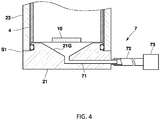
- a discharging mechanism 7 may be provided in the lower wall portion 21 of the container 2 to suck and discharge the powder sample (W).
- This discharging mechanism 7 may be provided with a function as a decompression pump of the above-mentioned embodiment.
- the discharging mechanism 7 comprises a discharging channel 71 arranged in the lower wall portion 21, an exhaust pipe 72 connected to the discharging channel 71, and a suction pump 73 arranged in the exhaust pipe 72. After the powder sample (W) is dispersed inside of the container 2 (after the container 2 is used), the suction pump 73 sucks and discharges the powder sample (W) deposited on the lower wall portion 21 from the discharging channel 71.
- a funnel-shaped guide surface 21G is formed on the inner surface of the lower wall portion 21 to guide the powder sample (W) toward the discharging channel 71.
- the guide surface 21G funnel-shaped, it is possible to prevent the powder sample (W) from flying up.
- a filter to remove the powder sample (W) may be arranged upstream of the suction pump 73 in the discharging channel 71 or the exhaust pipe 72.
- one or more mesh members 33 may be provided inside of the introducing tube 31 in the introducing mechanism 3.
- the mesh member 33 promotes dispersion of the powder sample (W).
- the mesh member 33 is arranged on a vacuum side in the introducing mechanism 3.
- the mesh member 33 is a mesh filter. This mesh member 33 may be arranged upstream or downstream of the narrowed portion 31S.
- the mesh member 33 As the powder sample (W) passes through the mesh member 33, it is possible to disperse the powder sample (W) whose particle size is smaller than the mesh size (mesh opening) of the mesh member 33. This makes it easy to take an observation image free from aggregated particles so that working hours required for the operation can be reduced. In addition, the particles that remain in an aggregated state remain on the mesh member so that it is possible to easily remove the particles that remain in the aggregated state. Furthermore, if a mesh member is changed to a mesh member having a different mesh size, it is possible to set conditions suitable for the power sample (W). In addition, a plurality of mesh members 33 with different mesh sizes may be provided. In this case, it is considered that the mesh members 33 with different mesh sizes are arranged inside of the introducing tube 31 in a descending order of the mesh size starting from the upstream side.
- the configuration is to place the powder sample (W) on the upper surface of the partition membrane 321 and to introduce the powder sample (W) into the introducing tube 31 by breaking the partition membrane 321 with the membrane breaking portion 322, however, the following configuration is also possible.
- the sample dispersing device having this configuration is a sample dispersing device that disperses a powder sample on an upper surface of an analytical member, and comprises a container having a placing surface on which the analytical member is placed, and an introducing mechanism that is arranged in the container and that introduces the powder sample into the container, and the introducing mechanism has an introducing tube inside of which the powder sample is housed and a gas that contains the powder sample is introduced into the container by a pressure difference between the inside and the outside of the container from a state in which the powder sample is housed inside of the introducing tube.
- a powder sample (W) is housed inside of the introducing tube 31, and with this state kept, a partition membrane 321 is broken by a membrane breaking portion 322 and the powder sample (W) is introduced into the inside of the container 2.
- the powder sample (W) housed inside of the introducing tube 31 is in a decompressed state.
- the powder sample (W) is housed in at least one (the second narrowed portion 31S in Fig. 6 ) of a plurality of the narrowed portions 31S of the introducing tube 31.
- the introducing tube 31 is divided into parts for each of the narrowed portions 31S, and after housing the powder sample (W) in one narrowed portion 31S in a disassembled state, the introducing tube 31 housing the powder sample (W) is formed by assembling the disassembled narrowed portions 31S. If the powder sample (W) comes out of the narrowed portion 31S in case that the powder sample (W) is housed in the narrowed portion 31S, a valve structure or a film may be provided at an opening portion of the narrowed portion 31S.
- the powder sample (W) is housed inside of the introducing tube 31 (narrowed portion 31S), and the partition membrane 321 is broken by the membrane breaking section 322 in a state wherein the container 2 is depressurized, then air flows into the inside of the introducing tube 31 from the outside so that the powder sample (W) is introduced into inside of the container 2.
- the powder sample (W) is not placed on the partition membrane 321, it is possible to solve the problem that the powder sample (W) remains on the partition membrane 321 and the desired amount of dispersion cannot be obtained.
- the powder sample (W) is placed inside of the introducing tube 31, since the shear force that acts on the group of particles in the aggregated state becomes weaker than a case wherein the powder sample (W) is placed on the partition membrane 321 and a distance to the analytical plate 10 can be shortened, it is possible to control the dispersed state of the powder sample (W) and to obtain the powder sample (W) in a desired state (aggregated state or a state wherein a mixed state is maintained).
- the covering member 4 may be provided with a charging mechanism to electrically charge the covering member 4.
- the covering member 4 is electrically charged with the same charge as that of the powder sample (W)
- the covering member 4 is electrically oppositely charged from the charge of the powder sample (W)
- the container 2 having the placing surface 2x on which the analytical plate 10 is placed may be made disposable without using the covering member 4 of the above-mentioned embodiment. There is no need of cleaning the container 2 if the container 2 itself is made to be disposable.
Landscapes
- Physics & Mathematics (AREA)
- Health & Medical Sciences (AREA)
- Life Sciences & Earth Sciences (AREA)
- Chemical & Material Sciences (AREA)
- Analytical Chemistry (AREA)
- Biochemistry (AREA)
- General Health & Medical Sciences (AREA)
- General Physics & Mathematics (AREA)
- Immunology (AREA)
- Pathology (AREA)
- Sampling And Sample Adjustment (AREA)
Abstract
Description
- The present claimed invention relates to a sample dispersing device and a sample dispersing method for dispersing a powder sample on an analytical member.
- Conventionally, in case of observing a powder sample with a microscope such as an electron microscope, a sample is prepared by dispersing the powder sample on an upper surface of an analytical member.
- As a device to prepare the sample, as shown in the
Patent document 1, there is a sampler dispersing device that introduces a powder sample into a container that houses a holding member (an analytical member) such as a glass plate and that attaches the powder sample dispersed in the container to the holding member. - For this type of the sample dispersing device, since the powder sample is scattered in all directions in the container and adheres to the inner surface of the container, it is necessary to conduct cleaning work such as washing with water or wiping in order to remove the particles that adheres to the inner surface of the container after use.
- However, since it is necessary to conduct the above-mentioned cleaning work manually for each preparation of the powder sample, not only the cleaning work is time-consuming but also it is difficult to prepare the powder samples efficiently. In addition, there is a risk of confusion with other powder samples due to variations in the cleaning states among the workers who conduct the above-mentioned cleaning work.
- [Patent document 1]
International Publication No. 2019 / 050035 - The present claimed invention was made in consideration of the above-mentioned problems, and a main object of this invention is to shorten cleaning time of a container in a sample dispersing device and to reduce variations of the cleaning state.
- More specifically, the sample dispersing device in accordance with this invention is a sample dispersing device for dispersing a powder sample on an upper surface of an analytical member, and is characterized by comprising a container that has a placing surface on which the analytical member is placed, an introducing mechanism that is arranged in the container and that introduces the powder sample into inside of the container, and a covering member that covers an inner surface of the container and that can be attached to and removed from the container.
- In accordance with the above-mentioned sample dispersing device, since the covering member that covers the inner surface of the container is removable from the container, it is possible to easily clean the container by replacing the covering member after use. As a result of this, it is possible to shorten the cleaning time of the container of the sample dispersing device, and to efficiently prepare samples with powder samples dispersed on the analytical member. In addition, since a part covered by the covering member can be cleaned by replacing the covering member, it is possible to reduce the variation of the cleaning condition. Furthermore, since the cleaning can be conducted efficiently and without variation, it is possible to reduce the risk of confusion with other powder samples. In addition, it is also possible to reduce the risk of damage to the container during cleaning.
- As a concrete embodiment of the container, conceived is that the container has a lower wall portion having the placing surface on its upper surface, an upper wall portion facing the lower wall portion, and a side wall portion connecting the lower wall portion and the upper wall portion and surrounding the placing surface.
- In accordance with this arrangement, a ratio of the inner surface of the side wall portion to the inner surface of the container becomes relatively large. For this reason, in order to make the effect of providing the covering member in a detachable manner remarkably, it is preferable that the covering member covers at least an inner surface of the side wall portion.
- In order both to facilitate the installation and the removal of the analytical member and to facilitate the replacement of the covering member with respect to the side wall portion, it is preferable that the container is configured so that at least the lower wall portion is separable from the side wall portion.
- It is preferable that the covering member is made of an elastic body having a sheet shape and covers the inner surface of the side wall portion by being arranged in an elastically deformed state inside of the side wall portion.
- In accordance with this arrangement, since the covering member is fixed in contact with the inner surface of the side wall portion by the elastic resilience of the covering member by elastically deforming the covering member into a cylindrical shape and placing it inside the side wall portion, it is possible to eliminate the need for a separate fixing mechanism for fixing the covering member. In addition, it is possible to facilitate the replacing work of the covering member.
- Most of the scattered powder is deposited on the lower wall portion. For this reason, it is preferable that a discharging mechanism that sucks and discharges the powder sample is arranged on the lower wall portion.
- In accordance with this arrangement, it is possible to reduce the burden of cleaning work by discharging the powder sample before the container is opened.
- In order to make it possible to visually recognize the inside of the container, it is preferable that the covering member is made of a material having light transmittance.
- As a concrete embodiment of the introducing mechanism, it is preferable that the introducing mechanism introduces a gas containing the powder sample into the container by means of a pressure difference between the inside and the outside of the container and has an introducing pipe through which the gas containing the powder sample flows and which is provided with a plurality of narrowed portions, and one or more mesh members arranged in the introducing pipe.
- In accordance with this arrangement, since the mesh members are provided in the introducing tube, it is possible to subdivide the powder sample introduced into the container so that the powder sample can be efficiently dispersed inside of the container.
- In addition, a sample dispersing method in accordance with this invention is a sample dispersing method using a sample dispersing device that has a container having a placing surface on which an analytical member is placed and an introducing mechanism that introduces a powder sample into the container, and is characterized by that the powder sample is introduced into the container by the introducing mechanism and dispersed on an upper surface of the analytical member in a state wherein an inner surface of the container is covered by a covering member that can be attached to and removed from the container.
- In accordance with the above-mentioned invention, the cleaning time of the container of the sample dispersing device can be shortened and the variation of the cleaning condition can be reduced.
-
- [
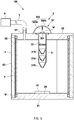
Fig. 1 ] Schematic diagram of a sample dispersing device in accordance with one embodiment of this invention. - [
Fig.2 ] Schematic diagram showing a state wherein a powder sample is dispersed in this embodiment. - [
Fig. 3 ] A perspective view showing one example of a procedure for mounting a covering member in accordance with this embodiment. - [
Fig. 4 ] A schematic diagram showing the sample dispersing device in accordance with a modified embodiment. - [
Fig. 5 ] A schematic diagram showing the sample dispersing device in accordance with a modified embodiment. - [
Fig. 6 ] A schematic diagram showing the sample dispersing device in accordance with a modified embodiment. - A
sample dispersing device 100 in accordance with one embodiment of the present claimed invention will be described below with reference to drawings. - The
sample dispersing device 100 of this embodiment is to disperse a powder sample (W) on an upper surface of ananalytical plate 10 as being an analytical member. Theanalytical plate 10 in this embodiment is a plate having a flat surface on its top. The analytical member is not limited to a plate-shaped plate, and various types of plates can be used according to the analytical device such as a microscope. - Concretely, as shown in
Fig. 1 , thesample dispersing device 100 has acontainer 2 having a placing surface on which theanalytical plate 10 is placed, anintroducing mechanism 3 that is arranged in thecontainer 2 and that introduces the powder sample (W) into inside of thecontainer 2, and a coveringmember 4 that covers the inner surface of thecontainer 2 and that is removable from thecontainer 2. - The
container 2 has alower wall portion 21 having a placing surface 2x on its upper surface, anupper wall portion 22 facing thelower wall portion 21, and aside wall portion 23 connected to thelower wall portion 21 and theupper wall portion 22 and surrounding the placing surface 2x. - The
lower wall portion 21 has a placing surface 2x on which theanalytical plate 10 is placed and the placing surface 2x is set, for example, in a center of thelower wall portion 21. A placing stand on which theanalytical plate 10 is placed is arranged in a center of thelower wall portion 21, and the upper surface of the placing stand may be used as the placing surface 2x. - The
upper wall portion 22 is provided with an introducingmechanism 3 and the introducingmechanism 3 is arranged, for example, in a center portion of theupper wall portion 22. In addition, theupper wall portion 22 is provided with anexhaust port 2P to make the inside of thecontainer 2 in vacuum, and theexhaust port 2P is connected to apressure reducing pump 6 throughpiping 5. The pressure in the inside of thecontainer 2 is reduced to a predetermined vacuum level by thepressure reducing pump 6. In addition, theupper wall portion 22 may be provided with an atmospheric opening port to open the inside of thecontainer 2 to the atmosphere. - The
side wall portion 23 has a cylindrical shape arranged between thelower wall portion 21 and theupper wall portion 22, and its lower end opening portion is closed by thelower wall portion 21 and its upper end opening portion is closed by theupper wall portion 22. Theside wall portion 23 of this embodiment is made of a material having light transmittance (for example, quartz glass, acrylic glass, etc.) so that the interior part can be seen. Theside wall portion 23 of this embodiment has a cylindrical shape. - The
container 2 is configured so that at least thelower wall portion 21 can be separated from theside wall portion 23. In this embodiment, not only thelower wall portion 21 but also theupper wall portion 22 is configured to be separable from theside wall portion 23. The space between theside wall portion 23 and thelower wall portion 21 is made airtight through a sealing member S1 such as an O-ring, and the space between theside wall portion 23 and theupper wall portion 22 is also made airtight through a sealing member S2 such as an O-ring. - The introducing
mechanism 3 introduces a gas containing the powder sample (W) into thecontainer 2 by means of a pressure difference between the inside and the outside of thecontainer 2. - Concretely, the introducing
mechanism 3 comprises an introducingtube 31 through which the gas containing the powder sample (W) flows and a supplyingportion 32 that supplies the powder sample (W) to the introducingtube 31. - The introducing
tube 31 is arranged along the vertical direction while penetrating theupper wall portion 22 of thecontainer 2. The introducingtube 31 is provided with a plurality of narrowedportions 31S between an upper end opening and a lower end opening of the introducingtube 31. The gas containing the powder sample - (W) flowing through the introducing
tube 31 is repeatedly compressed and expanded by the multiple narrowedportions 31S, and a shearing force is applied to a group of particles in an aggregated state to promote dispersion of the powder sample (W). The supplyingportion 32 is arranged at the upper end opening of the introducingtube 31. - The supplying
portion 32 comprises apartition membrane 321 that blocks the upper end opening of the introducingtube 31 and on which the powder sample (W) is placed and amembrane breaking portion 322 that breaks thepartition membrane 321 and supplies the powder sample (W) to the introducingtube 31. - The
partition membrane 321 has a strength that is substantially strong enough not to be broken even when the inside of thecontainer 2 is depressurized, and is a thin film, for example, made of resin. - The
membrane breaking portion 322 is for breaking thepartition membrane 321 in a state wherein inside of thecontainer 2 is depressurized, and consists of, for example, aneedle 322a. Theneedle 322a is fixed to an inner surface of anelastic body 322b that is roughly hemispherical in shape. Theelastic body 322b is arranged in such a way that theneedle 322a faces thepartition membrane 321. When theelastic body 322b is in a natural state, theneedle 322a is separated from thepartition membrane 321. When theelastic body 322b is pushed downward, theneedle 322a breaks thepartition membrane 321 so that the powder sample (W) placed on the upper surface of thepartition membrane 321 is introduced into the inside of thecontainer 2 through the introducingtube 31 due to the pressure difference between the inside and the outside of the container 2 (refer toFig. 2 ). - The covering
member 4 covers at least the inner surface of theside wall portion 23 of the inner surface of thecontainer 2. The coveringmember 4 of this embodiment is configured to cover generally the entire inner surface of theside wall portion 23. The coveringmember 4 is made of a light transmissive material (for example, a resin having light transmission characteristics) so that the inside of thecontainer 2 can be seen. The coveringmember 4 may cover a part of the inner surface of theside wall portion 23. For example, it may cover a lower half of the inner surface of theside wall portion 23 and may cover the inner surface of theside wall portion 23 below the lower end of the introducingtube 31, or it may cover the part of the inner surface of theside wall portion 23 to which the powder sample (W) easily adheres. - Concretely, the covering
member 4 is composed of an elastic body having a sheet shape, as shown inFig. 3 . The coveringmember 4 is configured to cover the inner surface of theside wall portion 23 by being arranged in a cylindrically elastically deformed state inside of theside wall portion 23. - Here, the covering
member 4 is arranged inside of theside wall portion 23 in a cylindrically elastically deformed state, and the coveringmember 4 expands due to its elastic return force so that the outer surface of the coveringmember 4 makes contact with the inner surface of theside wall portion 23. Since theside wall portion 23 has a cylindrical shape, the outer surface of the coveringmember 4 makes contact with generally whole part of the inner surface of theside wall portion 23. - A sample dispersing method using the sample dispersing device of this embodiment will be briefly explained.
- First, the covering
member 4 is mounted on the inside of theside wall portion 23. With this state kept, thelower wall portion 21 andupper wall portion 22 are mounted on theside wall portion 23, and theanalytical plate 10 is placed on the placing surface 2x of thelower wall portion 21. - With this state kept, the powder sample (W) is introduced into the
container 2 and the powder sample (W) is dispersed on the upper surface of theanalytical plate 10 by the use of the introducingmechanism 3. - Subsequently, the
lower wall portion 21 andupper wall portion 22 are dismounted from theside wall portion 23 and theanalytical plate 10 is dismounted. In addition, the coveringmember 4 is dismounted from the inner surface of theside wall portion 23. - In accordance with the
sample dispersing device 100 of this embodiment having the above-mentioned arrangement, since the coveringmember 4 that covers the inner surface of thecontainer 2 is detachable from thecontainer 2, the cleaning work of thecontainer 2 can be simplified by replacing the coveringmember 4 after use. As a result of this, it is possible to shorten the time required for cleaning thecontainer 2 of thesample dispersing device 100, and to efficiently prepare the sample wherein the powder sample (W) is dispersed on theanalytical plate 10. In addition, since a portion covered by the coveringmember 4 can be cleaned by replacing the coveringmember 4, it is possible to reduce the variation in the cleaning condition. Furthermore, since the cleaning can be done efficiently and evenly, it is possible to reduce the risk of confusion with other powder samples. In addition, it is also possible to reduce the risk of damage to thecontainer 2 or deterioration of thecontainer 2 during cleaning. - In addition, since the inner surface of the
side wall portion 23 to which the powder sample (W) relatively easily adheres and that occupies a large proportion of the inner surface is covered with the coveringmember 4, it is possible to make the effect of having the coveringmember 4 removable furthermore conspicuous. - Furthermore, since the
lower wall portion 21 is configured to be separable from theside wall portion 23, it is possible to facilitate installation and removal of theanalytical plate 10 and to facilitate replacement of the coveringmember 4 with respect to theside wall portion 23. - In addition, since the covering
member 4 is fixed in contact with the inner surface of theside wall portion 23 by its elastic return force just by elastically deforming the coveringmember 4 into a cylindrical shape and placing it inside of theside wall portion 23, it is possible to eliminate the need for an another separate fixing mechanism in order to fix the coveringmember 4. Furthermore, it is possible to facilitate an exchanging work of the coveringmember 4. - .
- The present invention is not limited to the above-mentioned embodiments.
- For example, the covering
member 4 of the above-mentioned embodiment covers the inner surface of theside wall portion 23 of thecontainer 2, but it may also cover the inner surface of thelower wall portion 21 or the inner surface of theupper wall portion 22 of thecontainer 2. - In case of covering the inner surface of the
lower wall portion 21 of thecontainer 2, it may be configured to cover the inner surface excluding the placing surface 2x, or it may be configured to cover the entire inner surface including the placing surface 2x. In case of covering the entire inner surface including the placing surface 2x, theanalytical plate 10 is placed on the coveringmember 4. - In addition, the above-mentioned
covering member 4 may be in the form of a sheet or a bag, for example, and may cover both the inner surface of theside wall portion 23 and the inner surface of thelower wall portion 21. - Furthermore, the covering
member 4 may be fixed to the inner surface of thecontainer 2 using an adhesive or other fixing means. - The covering
member 4 may be disposable or may be used repeatedly by washing. In case of a configuration wherein the sheet-shaped material is elastically deformed as in the above-mentioned embodiment, since the coveringmember 4 becomes sheet-shaped after removal, it becomes easy to clean the coveringmember 4. - As the introducing
mechanism 3 of the powder sample (W), in addition to the decompression type as described in the above-mentioned embodiment, it may be a pressurized type that uses compressed air to introduce the powder sample (W) into thecontainer 2, or it may be a free-fall type. In addition to the configuration of the introducingmechanism 3 arranged on theupper wall portion 22, it may also be installed on thelower wall portion 21, or on theside wall portion 23. - Furthermore, as shown in
Fig. 4 , a dischargingmechanism 7 may be provided in thelower wall portion 21 of thecontainer 2 to suck and discharge the powder sample (W). This dischargingmechanism 7 may be provided with a function as a decompression pump of the above-mentioned embodiment. - Concretely, the discharging
mechanism 7 comprises a dischargingchannel 71 arranged in thelower wall portion 21, anexhaust pipe 72 connected to the dischargingchannel 71, and asuction pump 73 arranged in theexhaust pipe 72. After the powder sample (W) is dispersed inside of the container 2 (after thecontainer 2 is used), thesuction pump 73 sucks and discharges the powder sample (W) deposited on thelower wall portion 21 from the dischargingchannel 71. - . Here, in order to increase the efficiency of discharging the powder sample (W) by the discharging
mechanism 7, a funnel-shapedguide surface 21G is formed on the inner surface of thelower wall portion 21 to guide the powder sample (W) toward the dischargingchannel 71. By making theguide surface 21G funnel-shaped, it is possible to prevent the powder sample (W) from flying up. In addition, it is also preferable to open the inside of thecontainer 2 to the atmosphere before discharging the powder sample (W) by the dischargingmechanism 7. Furthermore, a filter to remove the powder sample (W) may be arranged upstream of thesuction pump 73 in the dischargingchannel 71 or theexhaust pipe 72. - In addition, as shown in
Fig. 5 , one ormore mesh members 33 may be provided inside of the introducingtube 31 in the introducingmechanism 3. In addition to the narrowedportion 31S arranged in the introducingtube 31, themesh member 33 promotes dispersion of the powder sample (W). InFig. 5 , themesh member 33 is arranged on a vacuum side in the introducingmechanism 3. As mentioned above, since the powder sample (W) that is accelerated inside the introducingtube 31 due to the pressure difference collides with themesh member 33 by arranging themesh member 33 on the vacuum side, it is possible to refine the powder sample (W). Themesh member 33 is a mesh filter. Thismesh member 33 may be arranged upstream or downstream of the narrowedportion 31S. As the powder sample (W) passes through themesh member 33, it is possible to disperse the powder sample (W) whose particle size is smaller than the mesh size (mesh opening) of themesh member 33. This makes it easy to take an observation image free from aggregated particles so that working hours required for the operation can be reduced. In addition, the particles that remain in an aggregated state remain on the mesh member so that it is possible to easily remove the particles that remain in the aggregated state. Furthermore, if a mesh member is changed to a mesh member having a different mesh size, it is possible to set conditions suitable for the power sample (W). In addition, a plurality ofmesh members 33 with different mesh sizes may be provided. In this case, it is considered that themesh members 33 with different mesh sizes are arranged inside of the introducingtube 31 in a descending order of the mesh size starting from the upstream side. - In addition, in the above-described embodiment, the configuration is to place the powder sample (W) on the upper surface of the
partition membrane 321 and to introduce the powder sample (W) into the introducingtube 31 by breaking thepartition membrane 321 with themembrane breaking portion 322, however, the following configuration is also possible. - The sample dispersing device having this configuration is a sample dispersing device that disperses a powder sample on an upper surface of an analytical member, and comprises a container having a placing surface on which the analytical member is placed, and an introducing mechanism that is arranged in the container and that introduces the powder sample into the container, and the introducing mechanism has an introducing tube inside of which the powder sample is housed and a gas that contains the powder sample is introduced into the container by a pressure difference between the inside and the outside of the container from a state in which the powder sample is housed inside of the introducing tube.
- Concretely, as shown in
Fig. 6 , it may be configured that a powder sample (W) is housed inside of the introducingtube 31, and with this state kept, apartition membrane 321 is broken by amembrane breaking portion 322 and the powder sample (W) is introduced into the inside of thecontainer 2. In other words, in a state before thepartition membrane 321 is broken, the powder sample (W) housed inside of the introducingtube 31 is in a decompressed state. More specifically, it can be configured that the powder sample (W) is housed in at least one (the second narrowedportion 31S inFig. 6 ) of a plurality of the narrowedportions 31S of the introducingtube 31. InFig. 6 , the introducingtube 31 is divided into parts for each of the narrowedportions 31S, and after housing the powder sample (W) in one narrowedportion 31S in a disassembled state, the introducingtube 31 housing the powder sample (W) is formed by assembling the disassembled narrowedportions 31S. If the powder sample (W) comes out of the narrowedportion 31S in case that the powder sample (W) is housed in the narrowedportion 31S, a valve structure or a film may be provided at an opening portion of the narrowedportion 31S. - As mentioned above, the powder sample (W) is housed inside of the introducing tube 31 (narrowed
portion 31S), and thepartition membrane 321 is broken by themembrane breaking section 322 in a state wherein thecontainer 2 is depressurized, then air flows into the inside of the introducingtube 31 from the outside so that the powder sample (W) is introduced into inside of thecontainer 2. In this embodiment, since the powder sample (W) is not placed on thepartition membrane 321, it is possible to solve the problem that the powder sample (W) remains on thepartition membrane 321 and the desired amount of dispersion cannot be obtained. In addition, if the powder sample (W) is placed inside of the introducingtube 31, since the shear force that acts on the group of particles in the aggregated state becomes weaker than a case wherein the powder sample (W) is placed on thepartition membrane 321 and a distance to theanalytical plate 10 can be shortened, it is possible to control the dispersed state of the powder sample (W) and to obtain the powder sample (W) in a desired state (aggregated state or a state wherein a mixed state is maintained). - In the above-mentioned embodiment, the covering
member 4 may be provided with a charging mechanism to electrically charge the coveringmember 4. In this case, if the coveringmember 4 is electrically charged with the same charge as that of the powder sample (W), it is possible to make the powder sample (W) hardly adhere to the coveringmember 4 so that the powder particles (W) can be collected on thelower wall portion 21. In addition, if the coveringmember 4 is electrically oppositely charged from the charge of the powder sample (W), it is possible to make the powder sample (W) easily adhere to the coveringmember 4 so that the powder sample (W) that has not been dispersed on theanalytical plate 10 can be efficiently cleaned by replacing the coveringmember 4. - The
container 2 having the placing surface 2x on which theanalytical plate 10 is placed may be made disposable without using the coveringmember 4 of the above-mentioned embodiment. There is no need of cleaning thecontainer 2 if thecontainer 2 itself is made to be disposable. - In addition, the embodiment may be variously modified or combined without departing from a spirit of the present claimed invention.
-
- 100 ...
- sample dispersing device
- W ...
- powder sample
- 10 ...
- analytical plate (analytical member)
- 2x ...
- placing surface
- 2 ...
- container
- 21 ...
- lower wall portion
- 22 ...
- upper wall portion
- 23 ...
- side wall portion
- 3 ...
- introducing mechanism
- 31 ...
- introducing tube
- 31S ...
- narrowed portion
- 33 ...
- mesh member
- 4 ...
- covering member
- 7 ...
- discharging mechanism
Claims (8)
- A sample dispersing device for dispersing a powder sample on an upper surface of an analytical member, comprising
a container that has a placing surface on which the analytical member is placed, an introducing mechanism that is arranged in the container and that introduces the powder sample into inside of the container, and
a covering member that covers an inner surface of the container and that can be attached to and removed from the container. - The sample dispersing device described in claim 1, wherein
the container has a lower wall portion having the placing surface on its upper surface, an upper wall portion facing the lower wall portion, and a side wall portion connecting the lower wall portion and the upper wall portion and surrounding the placing surface, and
the covering member covers at least an inner surface of the side wall portion. - The sample dispersing device described in claim 2, wherein
the container is configured so that at least the lower wall portion is separable from the side wall portion. - The sample dispersing device described in claim 2, wherein
the covering member is made of an elastic body having a sheet shape and covers the inner surface of the side wall portion by being arranged in an elastically deformed state inside of the side wall portion. - The sample dispersing device described in claim 2, wherein
a discharging mechanism that sucks and discharges the powder sample is arranged on the lower wall portion. - The sample dispersing device described in claim 1, wherein
the covering member is made of a material having light transmittance. - The sample dispersing device described in claim 1, wherein
the introducing mechanism introduces a gas containing the powder sample into the container by means of a pressure difference between the inside and the outside of the container and has an introducing pipe through which the gas containing the powder sample flows and which is provided with a plurality of narrowed portions, and one or more mesh members arranged in the introducing pipe. - A sample dispersing method using a sample dispersing device that has a container having a placing surface on which an analytical member is placed and an introducing mechanism that introduces a powder sample into the container, wherein
the powder sample is introduced into the container by the introducing mechanism and dispersed on an upper surface of the analytical member in a state wherein an inner surface of the container is covered by a covering member that can be attached to and removed from the container.
Applications Claiming Priority (2)
| Application Number | Priority Date | Filing Date | Title |
|---|---|---|---|
| JP2020086003 | 2020-05-15 | ||
| JP2021049914A JP7585113B2 (en) | 2020-05-15 | 2021-03-24 | Sample dispersion device and sample dispersion method |
Publications (2)
| Publication Number | Publication Date |
|---|---|
| EP3910312A1 true EP3910312A1 (en) | 2021-11-17 |
| EP3910312B1 EP3910312B1 (en) | 2025-03-12 |
Family
ID=75936724
Family Applications (1)
| Application Number | Title | Priority Date | Filing Date |
|---|---|---|---|
| EP21173848.9A Active EP3910312B1 (en) | 2020-05-15 | 2021-05-14 | Sample dispersing device and sample dispersing method |
Country Status (3)
| Country | Link |
|---|---|
| US (1) | US12117379B2 (en) |
| EP (1) | EP3910312B1 (en) |
| CN (1) | CN113670679A (en) |
Citations (5)
| Publication number | Priority date | Publication date | Assignee | Title |
|---|---|---|---|---|
| US5507602A (en) * | 1994-10-14 | 1996-04-16 | J. M. Huber Corporation | Powder transfer from supersack containers and dispersion into a homogeneous slurry |
| US6102562A (en) * | 1999-05-04 | 2000-08-15 | Jenike & Johanson, Inc. | Removable container insert |
| JP2001242062A (en) * | 2000-02-28 | 2001-09-07 | Horiba Ltd | Sampling device for grain size distribution measurement sample |
| US20110120368A1 (en) * | 2004-06-08 | 2011-05-26 | Vincent Chapeau | Method and device for dispersing dry powders |
| WO2019050035A1 (en) | 2017-09-11 | 2019-03-14 | 株式会社堀場製作所 | Sample dispersing device |
Family Cites Families (13)
| Publication number | Priority date | Publication date | Assignee | Title |
|---|---|---|---|---|
| US3590888A (en) * | 1966-12-05 | 1971-07-06 | Clarence B Coleman | Composite container and method of handling fluent materials |
| US3537426A (en) | 1969-01-02 | 1970-11-03 | Ransburg Electro Coating Corp | Electrostatic coating apparatus |
| US4306557A (en) * | 1978-08-29 | 1981-12-22 | North Daniel A | Vacuum urological surgical irrigating solution collecting system |
| GB9212032D0 (en) * | 1992-06-05 | 1992-07-15 | Farrell Peter J | Collapsible container apparatus for fluid material |
| JP2001116668A (en) | 1999-10-21 | 2001-04-27 | Mitsubishi Nuclear Fuel Co Ltd | Electrodeposition cell |
| DE10129703A1 (en) * | 2001-06-22 | 2003-01-02 | Sofotec Gmbh & Co Kg | Atomizing system for a powder mixture and method for dry powder inhalers |
| CN100539924C (en) * | 2005-08-22 | 2009-09-16 | 乐金电子(天津)电器有限公司 | Removable element for filter |
| GB2479843B (en) * | 2007-05-18 | 2012-02-29 | Malvern Instr Ltd | Method and apparatus for dispersing a sample of particulate material |
| JP4974923B2 (en) | 2008-02-06 | 2012-07-11 | 浜松ホトニクス株式会社 | Nanomaterial observation sample preparation apparatus and preparation method |
| CN201505461U (en) * | 2009-09-11 | 2010-06-16 | 天津科技大学 | A scraper type molecular distillation device capable of quickly replacing the scraper |
| EP2655213B1 (en) * | 2010-12-21 | 2017-07-26 | Nestec S.A. | Container and pouch |
| SG11201601007TA (en) * | 2013-08-29 | 2016-03-30 | Exact Sciences Corp | Ergonomic stool specimen container and enclosing holder systems, methods, and kits |
| CN209173828U (en) * | 2018-11-09 | 2019-07-30 | 江苏嘉洋华联建筑装饰股份有限公司 | A finished putty construction device |
-
2021
- 2021-05-12 US US17/318,582 patent/US12117379B2/en active Active
- 2021-05-13 CN CN202110523377.5A patent/CN113670679A/en active Pending
- 2021-05-14 EP EP21173848.9A patent/EP3910312B1/en active Active
Patent Citations (5)
| Publication number | Priority date | Publication date | Assignee | Title |
|---|---|---|---|---|
| US5507602A (en) * | 1994-10-14 | 1996-04-16 | J. M. Huber Corporation | Powder transfer from supersack containers and dispersion into a homogeneous slurry |
| US6102562A (en) * | 1999-05-04 | 2000-08-15 | Jenike & Johanson, Inc. | Removable container insert |
| JP2001242062A (en) * | 2000-02-28 | 2001-09-07 | Horiba Ltd | Sampling device for grain size distribution measurement sample |
| US20110120368A1 (en) * | 2004-06-08 | 2011-05-26 | Vincent Chapeau | Method and device for dispersing dry powders |
| WO2019050035A1 (en) | 2017-09-11 | 2019-03-14 | 株式会社堀場製作所 | Sample dispersing device |
Also Published As
| Publication number | Publication date |
|---|---|
| US20210356365A1 (en) | 2021-11-18 |
| US12117379B2 (en) | 2024-10-15 |
| EP3910312B1 (en) | 2025-03-12 |
| CN113670679A (en) | 2021-11-19 |
Similar Documents
| Publication | Publication Date | Title |
|---|---|---|
| JP6901576B2 (en) | Sample disperser | |
| US3741001A (en) | Apparatus for sampling particulates in gases | |
| US12117379B2 (en) | Sample dispersing device and sample dispersing method | |
| EP1660863B1 (en) | Cascade impactor with individually driven impactor plates | |
| JP2021181978A (en) | Sample dispersion device and sample dispersion method | |
| US20210162329A1 (en) | Filter leakage monitoring device and particle separator provided with the same | |
| EP2485842A1 (en) | Sample preparation disposable devices and sample collection and preparation methods using same | |
| JP2012139652A (en) | Method for removing glycol from wire saw sludge | |
| WO2001081891A2 (en) | Sampler for eliminating particle-related artifacts for flue gas measurement | |
| KR20040016188A (en) | The probe system for gas analysis and method of sampling using thereof | |
| KR100661488B1 (en) | Liquid cell screening device for various cancer screening | |
| JPH08511957A (en) | Device for collecting and processing biological samples | |
| JP2015121561A (en) | Air purification apparatus and testing system therefor | |
| JP2011232287A (en) | Sample collection device, sample detector of gas turbine provided therewith and sample collection method | |
| CN216663051U (en) | Detachable multilayer cell filter | |
| JP3094186U (en) | Multi-stage filter | |
| CN220834763U (en) | Exhaust dust collection device | |
| US20160041087A1 (en) | Analysis and purging of materials in manufacturing processes | |
| CN219356543U (en) | Integral purifying device for building material laboratory | |
| EP3783361A1 (en) | Sampling tool for lubricating fluid analysis | |
| CN112763276A (en) | Particulate matter sampling device | |
| CN221199125U (en) | Sand-proof atmospheric sampler | |
| CN223970480U (en) | Water analyzer probe cleaning device | |
| CN220715007U (en) | Filter for separating viscous slurry and grinding medium | |
| CN218306871U (en) | Graphite powder dust collection device for lithium battery production |
Legal Events
| Date | Code | Title | Description |
|---|---|---|---|
| PUAI | Public reference made under article 153(3) epc to a published international application that has entered the european phase |
Free format text: ORIGINAL CODE: 0009012 |
|
| STAA | Information on the status of an ep patent application or granted ep patent |
Free format text: STATUS: THE APPLICATION HAS BEEN PUBLISHED |
|
| AK | Designated contracting states |
Kind code of ref document: A1 Designated state(s): AL AT BE BG CH CY CZ DE DK EE ES FI FR GB GR HR HU IE IS IT LI LT LU LV MC MK MT NL NO PL PT RO RS SE SI SK SM TR |
|
| B565 | Issuance of search results under rule 164(2) epc |
Effective date: 20211020 |
|
| STAA | Information on the status of an ep patent application or granted ep patent |
Free format text: STATUS: REQUEST FOR EXAMINATION WAS MADE |
|
| 17P | Request for examination filed |
Effective date: 20220419 |
|
| RBV | Designated contracting states (corrected) |
Designated state(s): AL AT BE BG CH CY CZ DE DK EE ES FI FR GB GR HR HU IE IS IT LI LT LU LV MC MK MT NL NO PL PT RO RS SE SI SK SM TR |
|
| STAA | Information on the status of an ep patent application or granted ep patent |
Free format text: STATUS: EXAMINATION IS IN PROGRESS |
|
| 17Q | First examination report despatched |
Effective date: 20230906 |
|
| P01 | Opt-out of the competence of the unified patent court (upc) registered |
Effective date: 20231108 |
|
| GRAP | Despatch of communication of intention to grant a patent |
Free format text: ORIGINAL CODE: EPIDOSNIGR1 |
|
| STAA | Information on the status of an ep patent application or granted ep patent |
Free format text: STATUS: GRANT OF PATENT IS INTENDED |
|
| INTG | Intention to grant announced |
Effective date: 20241112 |
|
| GRAS | Grant fee paid |
Free format text: ORIGINAL CODE: EPIDOSNIGR3 |
|
| GRAA | (expected) grant |
Free format text: ORIGINAL CODE: 0009210 |
|
| STAA | Information on the status of an ep patent application or granted ep patent |
Free format text: STATUS: THE PATENT HAS BEEN GRANTED |
|
| AK | Designated contracting states |
Kind code of ref document: B1 Designated state(s): AL AT BE BG CH CY CZ DE DK EE ES FI FR GB GR HR HU IE IS IT LI LT LU LV MC MK MT NL NO PL PT RO RS SE SI SK SM TR |
|
| REG | Reference to a national code |
Ref country code: GB Ref legal event code: FG4D |
|
| REG | Reference to a national code |
Ref country code: CH Ref legal event code: EP |
|
| REG | Reference to a national code |
Ref country code: DE Ref legal event code: R096 Ref document number: 602021027391 Country of ref document: DE |
|
| REG | Reference to a national code |
Ref country code: IE Ref legal event code: FG4D |
|
| PG25 | Lapsed in a contracting state [announced via postgrant information from national office to epo] |
Ref country code: RS Free format text: LAPSE BECAUSE OF FAILURE TO SUBMIT A TRANSLATION OF THE DESCRIPTION OR TO PAY THE FEE WITHIN THE PRESCRIBED TIME-LIMIT Effective date: 20250612 |
|
| PG25 | Lapsed in a contracting state [announced via postgrant information from national office to epo] |
Ref country code: FI Free format text: LAPSE BECAUSE OF FAILURE TO SUBMIT A TRANSLATION OF THE DESCRIPTION OR TO PAY THE FEE WITHIN THE PRESCRIBED TIME-LIMIT Effective date: 20250312 |
|
| PGFP | Annual fee paid to national office [announced via postgrant information from national office to epo] |
Ref country code: DE Payment date: 20250408 Year of fee payment: 5 |
|
| PG25 | Lapsed in a contracting state [announced via postgrant information from national office to epo] |
Ref country code: ES Free format text: LAPSE BECAUSE OF FAILURE TO SUBMIT A TRANSLATION OF THE DESCRIPTION OR TO PAY THE FEE WITHIN THE PRESCRIBED TIME-LIMIT Effective date: 20250312 |
|
| REG | Reference to a national code |
Ref country code: LT Ref legal event code: MG9D |
|
| PG25 | Lapsed in a contracting state [announced via postgrant information from national office to epo] |
Ref country code: NO Free format text: LAPSE BECAUSE OF FAILURE TO SUBMIT A TRANSLATION OF THE DESCRIPTION OR TO PAY THE FEE WITHIN THE PRESCRIBED TIME-LIMIT Effective date: 20250612 |
|
| PG25 | Lapsed in a contracting state [announced via postgrant information from national office to epo] |
Ref country code: HR Free format text: LAPSE BECAUSE OF FAILURE TO SUBMIT A TRANSLATION OF THE DESCRIPTION OR TO PAY THE FEE WITHIN THE PRESCRIBED TIME-LIMIT Effective date: 20250312 |
|
| REG | Reference to a national code |
Ref country code: NL Ref legal event code: MP Effective date: 20250312 |
|
| PG25 | Lapsed in a contracting state [announced via postgrant information from national office to epo] |
Ref country code: LV Free format text: LAPSE BECAUSE OF FAILURE TO SUBMIT A TRANSLATION OF THE DESCRIPTION OR TO PAY THE FEE WITHIN THE PRESCRIBED TIME-LIMIT Effective date: 20250312 |
|
| PG25 | Lapsed in a contracting state [announced via postgrant information from national office to epo] |
Ref country code: GR Free format text: LAPSE BECAUSE OF FAILURE TO SUBMIT A TRANSLATION OF THE DESCRIPTION OR TO PAY THE FEE WITHIN THE PRESCRIBED TIME-LIMIT Effective date: 20250613 Ref country code: BG Free format text: LAPSE BECAUSE OF FAILURE TO SUBMIT A TRANSLATION OF THE DESCRIPTION OR TO PAY THE FEE WITHIN THE PRESCRIBED TIME-LIMIT Effective date: 20250312 |
|
| REG | Reference to a national code |
Ref country code: AT Ref legal event code: MK05 Ref document number: 1775361 Country of ref document: AT Kind code of ref document: T Effective date: 20250312 |
|
| PG25 | Lapsed in a contracting state [announced via postgrant information from national office to epo] |
Ref country code: NL Free format text: LAPSE BECAUSE OF FAILURE TO SUBMIT A TRANSLATION OF THE DESCRIPTION OR TO PAY THE FEE WITHIN THE PRESCRIBED TIME-LIMIT Effective date: 20250312 |
|
| PG25 | Lapsed in a contracting state [announced via postgrant information from national office to epo] |
Ref country code: SE Free format text: LAPSE BECAUSE OF FAILURE TO SUBMIT A TRANSLATION OF THE DESCRIPTION OR TO PAY THE FEE WITHIN THE PRESCRIBED TIME-LIMIT Effective date: 20250312 |
|
| PG25 | Lapsed in a contracting state [announced via postgrant information from national office to epo] |
Ref country code: SM Free format text: LAPSE BECAUSE OF FAILURE TO SUBMIT A TRANSLATION OF THE DESCRIPTION OR TO PAY THE FEE WITHIN THE PRESCRIBED TIME-LIMIT Effective date: 20250312 |
|
| PG25 | Lapsed in a contracting state [announced via postgrant information from national office to epo] |
Ref country code: PT Free format text: LAPSE BECAUSE OF FAILURE TO SUBMIT A TRANSLATION OF THE DESCRIPTION OR TO PAY THE FEE WITHIN THE PRESCRIBED TIME-LIMIT Effective date: 20250714 |
|
| PG25 | Lapsed in a contracting state [announced via postgrant information from national office to epo] |
Ref country code: IT Free format text: LAPSE BECAUSE OF FAILURE TO SUBMIT A TRANSLATION OF THE DESCRIPTION OR TO PAY THE FEE WITHIN THE PRESCRIBED TIME-LIMIT Effective date: 20250312 Ref country code: PL Free format text: LAPSE BECAUSE OF FAILURE TO SUBMIT A TRANSLATION OF THE DESCRIPTION OR TO PAY THE FEE WITHIN THE PRESCRIBED TIME-LIMIT Effective date: 20250312 |
|
| PG25 | Lapsed in a contracting state [announced via postgrant information from national office to epo] |
Ref country code: AT Free format text: LAPSE BECAUSE OF FAILURE TO SUBMIT A TRANSLATION OF THE DESCRIPTION OR TO PAY THE FEE WITHIN THE PRESCRIBED TIME-LIMIT Effective date: 20250312 |
|
| PG25 | Lapsed in a contracting state [announced via postgrant information from national office to epo] |
Ref country code: CZ Free format text: LAPSE BECAUSE OF FAILURE TO SUBMIT A TRANSLATION OF THE DESCRIPTION OR TO PAY THE FEE WITHIN THE PRESCRIBED TIME-LIMIT Effective date: 20250312 Ref country code: EE Free format text: LAPSE BECAUSE OF FAILURE TO SUBMIT A TRANSLATION OF THE DESCRIPTION OR TO PAY THE FEE WITHIN THE PRESCRIBED TIME-LIMIT Effective date: 20250312 |
|
| PG25 | Lapsed in a contracting state [announced via postgrant information from national office to epo] |
Ref country code: RO Free format text: LAPSE BECAUSE OF FAILURE TO SUBMIT A TRANSLATION OF THE DESCRIPTION OR TO PAY THE FEE WITHIN THE PRESCRIBED TIME-LIMIT Effective date: 20250312 |
|
| PG25 | Lapsed in a contracting state [announced via postgrant information from national office to epo] |
Ref country code: SK Free format text: LAPSE BECAUSE OF FAILURE TO SUBMIT A TRANSLATION OF THE DESCRIPTION OR TO PAY THE FEE WITHIN THE PRESCRIBED TIME-LIMIT Effective date: 20250312 |
|
| PG25 | Lapsed in a contracting state [announced via postgrant information from national office to epo] |
Ref country code: IS Free format text: LAPSE BECAUSE OF FAILURE TO SUBMIT A TRANSLATION OF THE DESCRIPTION OR TO PAY THE FEE WITHIN THE PRESCRIBED TIME-LIMIT Effective date: 20250712 |
|
| REG | Reference to a national code |
Ref country code: DE Ref legal event code: R097 Ref document number: 602021027391 Country of ref document: DE |
|
| REG | Reference to a national code |
Ref country code: CH Ref legal event code: H13 Free format text: ST27 STATUS EVENT CODE: U-0-0-H10-H13 (AS PROVIDED BY THE NATIONAL OFFICE) Effective date: 20251223 |
|
| PG25 | Lapsed in a contracting state [announced via postgrant information from national office to epo] |
Ref country code: DK Free format text: LAPSE BECAUSE OF FAILURE TO SUBMIT A TRANSLATION OF THE DESCRIPTION OR TO PAY THE FEE WITHIN THE PRESCRIBED TIME-LIMIT Effective date: 20250312 |
|
| PG25 | Lapsed in a contracting state [announced via postgrant information from national office to epo] |
Ref country code: LU Free format text: LAPSE BECAUSE OF NON-PAYMENT OF DUE FEES Effective date: 20250514 |
|
| PLBE | No opposition filed within time limit |
Free format text: ORIGINAL CODE: 0009261 |
|
| STAA | Information on the status of an ep patent application or granted ep patent |
Free format text: STATUS: NO OPPOSITION FILED WITHIN TIME LIMIT |
|
| PG25 | Lapsed in a contracting state [announced via postgrant information from national office to epo] |
Ref country code: CH Free format text: LAPSE BECAUSE OF NON-PAYMENT OF DUE FEES Effective date: 20250531 |
|
| REG | Reference to a national code |
Ref country code: CH Ref legal event code: L10 Free format text: ST27 STATUS EVENT CODE: U-0-0-L10-L00 (AS PROVIDED BY THE NATIONAL OFFICE) Effective date: 20260121 |
|
| REG | Reference to a national code |
Ref country code: BE Ref legal event code: MM Effective date: 20250531 |
|
| PG25 | Lapsed in a contracting state [announced via postgrant information from national office to epo] |
Ref country code: MC Free format text: LAPSE BECAUSE OF FAILURE TO SUBMIT A TRANSLATION OF THE DESCRIPTION OR TO PAY THE FEE WITHIN THE PRESCRIBED TIME-LIMIT Effective date: 20250312 |
|
| 26N | No opposition filed |
Effective date: 20251215 |
|
| PGFP | Annual fee paid to national office [announced via postgrant information from national office to epo] |
Ref country code: GB Payment date: 20260323 Year of fee payment: 6 |
|
| PG25 | Lapsed in a contracting state [announced via postgrant information from national office to epo] |
Ref country code: IE Free format text: LAPSE BECAUSE OF NON-PAYMENT OF DUE FEES Effective date: 20250514 |
|
| PG25 | Lapsed in a contracting state [announced via postgrant information from national office to epo] |
Ref country code: BE Free format text: LAPSE BECAUSE OF NON-PAYMENT OF DUE FEES Effective date: 20250531 |
|
| PG25 | Lapsed in a contracting state [announced via postgrant information from national office to epo] |
Ref country code: FR Free format text: LAPSE BECAUSE OF NON-PAYMENT OF DUE FEES Effective date: 20250531 |