EP3910256A1 - Air conditioning and ventilation system - Google Patents
Air conditioning and ventilation system Download PDFInfo
- Publication number
- EP3910256A1 EP3910256A1 EP19909600.9A EP19909600A EP3910256A1 EP 3910256 A1 EP3910256 A1 EP 3910256A1 EP 19909600 A EP19909600 A EP 19909600A EP 3910256 A1 EP3910256 A1 EP 3910256A1
- Authority
- EP
- European Patent Office
- Prior art keywords
- air
- ventilation
- conditioning
- standard
- rate
- Prior art date
- Legal status (The legal status is an assumption and is not a legal conclusion. Google has not performed a legal analysis and makes no representation as to the accuracy of the status listed.)
- Granted
Links
- 238000009423 ventilation Methods 0.000 title claims abstract description 364
- 238000004378 air conditioning Methods 0.000 title claims abstract description 231
- 239000003507 refrigerant Substances 0.000 claims abstract description 41
- 238000011084 recovery Methods 0.000 claims abstract description 17
- 230000004913 activation Effects 0.000 claims abstract description 5
- 238000001816 cooling Methods 0.000 claims description 23
- 238000010438 heat treatment Methods 0.000 claims description 18
- 238000010586 diagram Methods 0.000 description 20
- 230000007423 decrease Effects 0.000 description 7
- 238000007791 dehumidification Methods 0.000 description 5
- 238000000034 method Methods 0.000 description 5
- 230000008569 process Effects 0.000 description 5
- 230000008859 change Effects 0.000 description 4
- 230000000694 effects Effects 0.000 description 3
- 230000004048 modification Effects 0.000 description 3
- 238000012986 modification Methods 0.000 description 3
- 238000004891 communication Methods 0.000 description 2
- 238000011109 contamination Methods 0.000 description 2
- 238000009413 insulation Methods 0.000 description 2
- 230000009467 reduction Effects 0.000 description 2
- 230000006870 function Effects 0.000 description 1
- 230000004044 response Effects 0.000 description 1
Images


Classifications
-
- F—MECHANICAL ENGINEERING; LIGHTING; HEATING; WEAPONS; BLASTING
- F24—HEATING; RANGES; VENTILATING
- F24F—AIR-CONDITIONING; AIR-HUMIDIFICATION; VENTILATION; USE OF AIR CURRENTS FOR SCREENING
- F24F11/00—Control or safety arrangements
- F24F11/62—Control or safety arrangements characterised by the type of control or by internal processing, e.g. using fuzzy logic, adaptive control or estimation of values
- F24F11/63—Electronic processing
- F24F11/65—Electronic processing for selecting an operating mode
-
- F—MECHANICAL ENGINEERING; LIGHTING; HEATING; WEAPONS; BLASTING
- F24—HEATING; RANGES; VENTILATING
- F24F—AIR-CONDITIONING; AIR-HUMIDIFICATION; VENTILATION; USE OF AIR CURRENTS FOR SCREENING
- F24F11/00—Control or safety arrangements
- F24F11/70—Control systems characterised by their outputs; Constructional details thereof
- F24F11/72—Control systems characterised by their outputs; Constructional details thereof for controlling the supply of treated air, e.g. its pressure
- F24F11/74—Control systems characterised by their outputs; Constructional details thereof for controlling the supply of treated air, e.g. its pressure for controlling air flow rate or air velocity
- F24F11/77—Control systems characterised by their outputs; Constructional details thereof for controlling the supply of treated air, e.g. its pressure for controlling air flow rate or air velocity by controlling the speed of ventilators
-
- F—MECHANICAL ENGINEERING; LIGHTING; HEATING; WEAPONS; BLASTING
- F24—HEATING; RANGES; VENTILATING
- F24F—AIR-CONDITIONING; AIR-HUMIDIFICATION; VENTILATION; USE OF AIR CURRENTS FOR SCREENING
- F24F11/00—Control or safety arrangements
- F24F11/0001—Control or safety arrangements for ventilation
-
- F—MECHANICAL ENGINEERING; LIGHTING; HEATING; WEAPONS; BLASTING
- F24—HEATING; RANGES; VENTILATING
- F24F—AIR-CONDITIONING; AIR-HUMIDIFICATION; VENTILATION; USE OF AIR CURRENTS FOR SCREENING
- F24F11/00—Control or safety arrangements
- F24F11/30—Control or safety arrangements for purposes related to the operation of the system, e.g. for safety or monitoring
- F24F11/46—Improving electric energy efficiency or saving
-
- F—MECHANICAL ENGINEERING; LIGHTING; HEATING; WEAPONS; BLASTING
- F24—HEATING; RANGES; VENTILATING
- F24F—AIR-CONDITIONING; AIR-HUMIDIFICATION; VENTILATION; USE OF AIR CURRENTS FOR SCREENING
- F24F11/00—Control or safety arrangements
- F24F11/70—Control systems characterised by their outputs; Constructional details thereof
- F24F11/72—Control systems characterised by their outputs; Constructional details thereof for controlling the supply of treated air, e.g. its pressure
- F24F11/74—Control systems characterised by their outputs; Constructional details thereof for controlling the supply of treated air, e.g. its pressure for controlling air flow rate or air velocity
-
- F—MECHANICAL ENGINEERING; LIGHTING; HEATING; WEAPONS; BLASTING
- F24—HEATING; RANGES; VENTILATING
- F24F—AIR-CONDITIONING; AIR-HUMIDIFICATION; VENTILATION; USE OF AIR CURRENTS FOR SCREENING
- F24F7/00—Ventilation
- F24F7/007—Ventilation with forced flow
-
- F—MECHANICAL ENGINEERING; LIGHTING; HEATING; WEAPONS; BLASTING
- F24—HEATING; RANGES; VENTILATING
- F24F—AIR-CONDITIONING; AIR-HUMIDIFICATION; VENTILATION; USE OF AIR CURRENTS FOR SCREENING
- F24F11/00—Control or safety arrangements
- F24F11/0001—Control or safety arrangements for ventilation
- F24F2011/0002—Control or safety arrangements for ventilation for admittance of outside air
-
- F—MECHANICAL ENGINEERING; LIGHTING; HEATING; WEAPONS; BLASTING
- F24—HEATING; RANGES; VENTILATING
- F24F—AIR-CONDITIONING; AIR-HUMIDIFICATION; VENTILATION; USE OF AIR CURRENTS FOR SCREENING
- F24F2110/00—Control inputs relating to air properties
- F24F2110/10—Temperature
-
- F—MECHANICAL ENGINEERING; LIGHTING; HEATING; WEAPONS; BLASTING
- F24—HEATING; RANGES; VENTILATING
- F24F—AIR-CONDITIONING; AIR-HUMIDIFICATION; VENTILATION; USE OF AIR CURRENTS FOR SCREENING
- F24F2110/00—Control inputs relating to air properties
- F24F2110/20—Humidity
-
- F—MECHANICAL ENGINEERING; LIGHTING; HEATING; WEAPONS; BLASTING
- F24—HEATING; RANGES; VENTILATING
- F24F—AIR-CONDITIONING; AIR-HUMIDIFICATION; VENTILATION; USE OF AIR CURRENTS FOR SCREENING
- F24F2140/00—Control inputs relating to system states
- F24F2140/50—Load
-
- Y—GENERAL TAGGING OF NEW TECHNOLOGICAL DEVELOPMENTS; GENERAL TAGGING OF CROSS-SECTIONAL TECHNOLOGIES SPANNING OVER SEVERAL SECTIONS OF THE IPC; TECHNICAL SUBJECTS COVERED BY FORMER USPC CROSS-REFERENCE ART COLLECTIONS [XRACs] AND DIGESTS
- Y02—TECHNOLOGIES OR APPLICATIONS FOR MITIGATION OR ADAPTATION AGAINST CLIMATE CHANGE
- Y02B—CLIMATE CHANGE MITIGATION TECHNOLOGIES RELATED TO BUILDINGS, e.g. HOUSING, HOUSE APPLIANCES OR RELATED END-USER APPLICATIONS
- Y02B30/00—Energy efficient heating, ventilation or air conditioning [HVAC]
- Y02B30/70—Efficient control or regulation technologies, e.g. for control of refrigerant flow, motor or heating
Abstract
Description
- The present invention relates to an air-conditioning ventilation system including a ventilation device and an air-conditioning apparatus.
- In recent years, due to an increase in airtightness and thermal insulation of building envelops, it has become common to ventilate continuously 24 hours. Thus, it is required by law to install equipment that replaces an amount of air corresponding to half the indoor capacity in one hour. Also, due to an increase in airtightness and thermal insulation of building envelops, the air conditioning load is reduced, so that installed air-conditioning apparatuses are more often operated with an air-conditioning capacity less than or equal to half the maximum air-conditioning capacity thereof.
- Generally, a ventilation device and an air-conditioning apparatus operate independently, and do not functionally cooperate with each other. Although it may be possible to reduce the power consumption of the air-conditioning apparatus and improve the thermal environment by temporarily increasing or reducing the ventilation rate, there is no communication means between the air-conditioning apparatus and the ventilation device, and therefore their functions are not effectively used.
- To avoid this problem, there has been a system that communicably connects a ventilation device and an air-conditioning apparatus to make the ventilation device and the air-conditioning apparatus cooperate with each other (see Patent Literature 1). In
Patent Literature 1, the ventilation rate of a ventilation device is controlled based on the power consumption of an air-conditioning apparatus. Specifically, when the power consumption of the air-conditioning apparatus exceeds a predetermined setting value, the ventilation rate is changed from "high" to "low" to reduce the amount of outdoor air to be suctioned, thereby reducing the power consumption of the air-conditioning apparatus. - Patent Literature 1:
Japanese Unexamined Patent Application Publication No. 2012-17868 - In
Patent Literature 1, the ventilation rate is set based on the power consumption of the air-conditioning apparatus. However, if ventilation is continued at the set ventilation rate for a long period of time, the following problem occurs. For example, if the ventilation rate is maintained at "low" for a long period of time, the required amount of ventilation cannot be secured. - The present invention has been made to overcome the above problem, and an object thereof is to provide an air-conditioning ventilation system capable of maintaining an appropriate amount of ventilation during operation.
- An air-conditioning ventilation system according to an embodiment of the present invention includes: a ventilation device configured to ventilate an air-conditioned space while controlling a ventilation rate; an air-conditioning apparatus including a heat exchanger configured to exchange heat between refrigerant and air, the air-conditioning apparatus being configured to operate while controlling an air-conditioning capacity thereof to bring an indoor temperature in the air-conditioned space to a setting temperature; and a controller configured to perform normal control that causes the ventilation device to operate to ventilate the air-conditioned space at a ventilation rate corresponding to the air-conditioning capacity of the air-conditioning apparatus, and recovery control that controls the ventilation rate of the ventilation device such that an integrated value of an amount of ventilation for a time duration from activation of the ventilation device under the normal control falls within a standard ventilation range including a standard integrated value of an amount of ventilation obtained by causing the ventilation device to operate to ventilate the air-conditioned space at a standard ventilation rate for a time duration having a same length as the time duration. Advantageous Effects of Invention
- According to the air-conditioning ventilation system of the above embodiment of the present invention, the controller controls the ventilation rate of the ventilation device such that the integrated value of the amount of ventilation falls within the standard ventilation range including the standard integrated value. Therefore, it is possible to maintain an appropriate amount of ventilation during operation.
-
- [
Fig. 1] Fig. 1 is a schematic configuration diagram of an air-conditioning ventilation system according toEmbodiment 1 of the present invention. - [
Fig. 2] Fig. 2 is a configuration diagram of an air-conditioning apparatus according toEmbodiment 1 of the present invention. - [
Fig. 3] Fig. 3 is a diagram for explaining an air-conditioning capacity control amount AQa used for air-conditioning capacity control of the air-conditioning apparatus according toEmbodiment 1 of the present invention. - [
Fig. 4] Fig. 4 is a diagram for explaining an air-conditioning capacity control amount AQb used for air-conditioning capacity control of the air-conditioning apparatus according toEmbodiment 1 of the present invention. - [
Fig. 5] Fig. 5 is a diagram for explaining ventilation rate control on the ventilation device according toEmbodiment 1 of the present invention. - [
Fig. 6] Fig. 6 is a flowchart illustrating a ventilation rate control operation of the ventilation device according toEmbodiment 1 of the present invention. - [
Fig. 7] Fig. 7 is a diagram for explaining a recovery control operation of insufficient ventilation by the air-conditioning ventilation system according toEmbodiment 1 of the present invention. - [
Fig. 8] Fig. 8 is a diagram for explaining ventilation rate control on the ventilation device during a cooling operation according toEmbodiment 1 of the present invention. - [
Fig. 9] Fig. 9 is a flowchart illustrating a ventilation rate control operation of the ventilation device during a cooling operation according toEmbodiment 2 of the present invention. - [
Fig. 10] Fig. 10 is a diagram for explaining a recovery control operation of the amount of ventilation by an air-conditioning ventilation system according toEmbodiment 2 of the present invention. - [
Fig. 11] Fig. 11 is a diagram for explaining ventilation rate control on the ventilation device during a heating operation according toEmbodiment 2 of the present invention. - [
Fig. 12] Fig. 12 is a flowchart illustrating a ventilation rate control operation of the ventilation device during a heating operation according toEmbodiment 2 of the present invention. - [
Fig. 13] Fig. 13 is a diagram illustrating a modification of the air-conditioning ventilation systems according toEmbodiments -
Fig. 1 is a schematic configuration diagram of an air-conditioning ventilation system according toEmbodiment 1 of the present invention.Fig. 2 is a configuration diagram of an air-conditioning apparatus according toEmbodiment 1 of the present invention. The configuration and operation of the air-conditioning ventilation system according toEmbodiment 1 of the present invention will be described with reference toFigs. 1 and 2 . - The air-conditioning ventilation system includes an air-
conditioning apparatus 2 configured to condition air in an air-conditionedspace 1, aventilation device 3 configured to ventilate the air-conditionedspace 1, and acontroller 4. Theventilation device 3 includes anexhaust fan 13 configured to exhaust air from the air-conditionedspace 1 to the outside, and an air-supply fan 14 configured to introduce outdoor air to the indoor space. Theexhaust fan 13 and the air-supply fan 14 are configured such that the ventilation rate is adjustable in different levels. - The
ventilation device 3 operates continuously 24 hours to ventilate the air-conditionedspace 1. The ventilation rate is adjustable in three levels including "standard" for securing the amount of ventilation corresponding to half the indoor capacity in one hour, "high" that is higher than "standard", and "low" that is lower than "standard". The rotation speeds of theexhaust fan 13 and the air-supply fan 14 are determined in advance for each of "low", "standard", and "high", and theventilation device 3 operates each of theexhaust fan 13 and the air-supply fan 14 at a rotation speed corresponding to the level of the ventilation rate. When the air-conditioning apparatus 2 is stopped, theventilation device 3 operates at "standard". When theventilation device 3 operates at "standard", a required amount of ventilation can be secured. Note that as described above, the ventilation rate of "standard" does not have to be set based on the ventilation rate for securing the amount of ventilation corresponding to half the indoor capacity in one hour, and may be set based on the progress of contamination indoors or other factors. Further, the number of levels in which the ventilation rate is adjusted is not limited to three, and may be greater than three. The ventilation rate only needs to be adjustable in at least three levels. - Referring to
Fig. 2 , the air-conditioning apparatus 2 includes, in a casing 2a, acirculation fan 6 and a heat exchanger 7. The air-conditioning apparatus 2 further includes atemperature sensor 9 configured to measure an indoor temperature of the air-conditionedspace 1, atemperature sensor 10 configured to measure a temperature of the refrigerant flowing through the heat exchanger 7, atemperature sensor 11 configured to measure a blown-out air temperature, and ahumidity sensor 12 that calculates a relative humidity in the air-conditionedspace 1. - The casing 2a has an
air inlet 5 and anair outlet 8. Thecirculation fan 6 suctions the indoor air of the air-conditionedspace 1 into the casing 2a through theair inlet 5, causes the air to pass through the heat exchanger 7, and blows out the air into the air-conditionedspace 1 through theair outlet 8. The heat exchanger 7 is connected to a compressor, a heat exchanger, a pressure reducing device, and other devices disposed in an outdoor unit (not illustrated) by pipes to form a refrigerant circuit. The air-conditioning apparatus 2 cools and heats the air-conditionedspace 1, by causing refrigerant to circulate in the refrigerant circuit such that the refrigerant exchanges heat with air in the heat exchanger 7. - The air-
conditioning apparatus 2 controls the air-conditioning capacity to bring the indoor temperature in the air-conditionedspace 1 to a setting temperature that is set from, for example, a remote control device. Further, the air-conditioning apparatus 2 obtains the actual air-conditioning capacity of the air-conditioning apparatus 2 during operation, and transmits the obtained air-conditioning capacity to thecontroller 4. The actual air-conditioning capacity is obtained by multiplying a temperature difference between the indoor temperature measured by thetemperature sensor 9 and the blown-out air temperature measured by thetemperature sensor 11, by a known air volume of thecirculation fan 6. - The
controller 4 is a device configured to make the air-conditioning apparatus 2 and theventilation device 3 cooperate with each other, and is communicably connected to the air-conditioning apparatus 2 and theventilation device 3. The communication may be wired, or may be wireless. InFig. 1 , the arrows connecting the devices indicate the flow of information among the devices. Thecontroller 4 includes dedicated hardware or a central processing unit (CPU) that executes a program stored in a memory. Thecontroller 4 may be a separate unit from the air-conditioning apparatus 2 as illustrated inFig. 1 , or may be an integral unit with the air-conditioning apparatus 2. - The
controller 4 controls theventilation device 3 based on information received from the air-conditioning apparatus 2. Thecontroller 4 includes normal control that causes theventilation device 3 to operate at a ventilation rate corresponding to the air-conditioning capacity of the air-conditioning apparatus 2, and recovery control that avoids insufficient ventilation or excess ventilation due to the normal control. The control on theventilation device 3 will be described below. - The following describes the operation of the air-conditioning ventilation system. The operation of the air-conditioning ventilation system will be described by taking a cooling operation as an example.
- First, the operation of the air-
conditioning apparatus 2 will be described. When the operation of the air-conditioning apparatus 2 is started, thecirculation fan 6 operates, and refrigerant flows through the heat exchanger 7. During a cooling operation, low-temperature refrigerant is supplied from the outdoor unit (not illustrated) to the heat exchanger 7. The refrigerant that has been supplied to the heat exchanger 7 exchanges heat with air sent from thecirculation fan 6 to the heat exchanger 7, and cools the air. As a result, the air-conditionedspace 1 is cooled. The temperature of refrigerant supplied to the heat exchanger 7 varies with the air-conditioning capacity of the air-conditioning apparatus 2. During a cooling operation, the temperature decreases when the air-conditioning capacity is increased. During a heating operation, the temperature increases when the air-conditioning capacity is increased. - The air-
conditioning apparatus 2 operates while controlling the air-conditioning capacity such that the indoor temperature measured by thetemperature sensor 9 is maintained at the setting temperature. The following describes air-conditioning capacity control of the air-conditioning apparatus 2. -
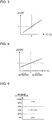
Fig. 3 is a diagram for explaining an air-conditioning capacity control amount ΔQa used for air-conditioning capacity control of the air-conditioning apparatus according toEmbodiment 1 of the present invention. InFig. 3 , the horizontal axis represents a temperature difference ΔT between the indoor temperature and a setting temperature, and the vertical axis represents ΔQa.Fig. 4 is a diagram for explaining an air-conditioning capacity control amount AQb used for air-conditioning capacity control of the air-conditioning apparatus according toEmbodiment 1 of the present invention. InFig. 4 , the horizontal axis represents a change amount R in the temperature difference ΔT, and the vertical axis represents ΔQb. The change amount R in the temperature difference ΔT is obtained by R = ΔT - ΔTn-1, where ΔT is the present temperature difference, and the ΔTn-1 is the previous temperature difference. - A control unit of the air-
conditioning apparatus 2 controls the air-conditioning capacity based on the temperature difference ΔT between the indoor temperature measured by thetemperature sensor 9 and a setting temperature. More specifically, the control unit of the air-conditioning apparatus 2 calculates an air-conditioning capacity command value Qn+1, for example, at control intervals of 30 minutes, using the following Equation (1):
- where Qn is the present air-conditioning capacity [W];
- ΔQa is the air-conditioning capacity control amount [W] corresponding to the temperature difference ΔT between the indoor temperature and the setting temperature; and
- ΔQb is the air-conditioning capacity control amount [W] corresponding to the tendency of changes in the temperature difference.
- Here, On+1 ≤ Qmax is satisfied.
- The air-conditioning capacity control amount ΔQa is obtained from the temperature difference ΔT and the graph illustrated in
Fig. 3 . The air-conditioning capacity control amount ΔQb is obtained from the change amount R of the temperature difference ΔT and the graph illustrated inFig. 4 . In this example, each of ΔQa and ΔQb are calculated using a graph. However, each of ΔQa and ΔQb may be calculated using a table or an arithmetic operation. - The control unit of the air-
conditioning apparatus 2 calculates the air-conditioning capacity command value On+1 at control intervals based on the above Equation (1), and controls the air-conditioning capacity of the air-conditioning apparatus 2 by, for example, transmitting the air-conditioning capacity command value On+1 to the compressor of the outdoor unit. In this manner, if the indoor temperature is higher than the setting temperature during a cooling operation, the air-conditioning apparatus 2 starts operating with an air-conditioning capacity corresponding to the temperature difference ΔT, and thereafter increases the air-conditioning capacity while ΔQa + ΔQb > 0. Then, the temperature difference ΔT continuously decreases toward zero, and ΔQa + ΔQb < 0 is satisfied at a certain point. In response, the air-conditioning apparatus 2 operates to reduce the air-conditioning capacity. With this operation, the indoor temperature becomes equal to the setting temperature. - As described above, the air-
conditioning apparatus 2 obtains the actual air-conditioning capacity while controlling the air-conditioning capacity based on the temperature difference ΔT between the indoor temperature and the setting temperature, and transmits information on the air-conditioning capacity to thecontroller 4. Thecontroller 4 controls the ventilation rate of theventilation device 3 based on the information on the air-conditioning capacity received from the air-conditioning apparatus 2. In the following, control of the ventilation rate will be described. -
Fig. 5 is a diagram for explaining ventilation rate control on the ventilation device according toEmbodiment 1 of the present invention. InFig. 5 , the vertical axis represents the maximum capacity rate [%]. - The ventilation rate of the
ventilation device 3 is set based on the air-conditioning capacity of the air-conditioning apparatus 2. In this example, the maximum capacity rate [%] is used as the index of the air-conditioning capacity. The maximum capacity rate may be the present air-conditioning capacity with respect to the physical maximum air-conditioning capacity of the air-conditioning apparatus 2, or may be the present rotation speed with respect to the physical maximum rotation speed of the compressor of the air-conditioning apparatus 2. Further, theventilation device 3 may be controlled based on the air-conditioning capacity itself. That is, theventilation device 3 only needs to be controlled based on the air-conditioning capacity. - In
Fig. 5 , the maximum capacity rate is divided into three levels using thresholds of 20% and 60%. If the maximum capacity rate is intermediate, the ventilation rate of theventilation device 3 is set to "standard". If the maximum capacity rate is low or high, the ventilation rate is set to "low". -
Fig. 6 is a flowchart illustrating a ventilation rate control operation of the ventilation device according toEmbodiment 1 of the present invention. - When the operation starts, the
controller 4 sets the ventilation rate of theventilation device 3 to "standard", and starts ventilation (step S1). Then, thecontroller 4 controls theventilation device 3 to the ventilation rate corresponding to the air-conditioning capacity received from the air-conditioning apparatus 2. Specifically, thecontroller 4 calculates the maximum capacity rate based on the air-conditioning capacity received from the air-conditioning apparatus 2, and determines whether the maximum capacity rate is less than or equal to 20% or greater than or equal to 60% (step S2). If the maximum capacity rate is not less than or equal to 20% nor greater than or equal to 60% (No in step S2), the process returns to step S1, in which thecontroller 4 continues ventilation while maintaining the ventilation rate of theventilation device 3 at "standard". In this manner, it is possible to stabilize the indoor temperature while securing the required amount of ventilation. - Meanwhile, if the maximum capacity rate is less than or equal to 20% or greater than or equal to 60% (Yes in step S2), the
controller 4 changes the ventilation rate of theventilation device 3 from "standard" to "low" (step S3) to reduce the amount of outdoor air to be suctioned. In this step, if the maximum capacity rate is greater than or equal to 60%, the air-conditioning capacity of the air-conditioning apparatus 2 is high. Accordingly, it becomes possible to quickly form a comfortable cool environment by reducing the amount of outdoor air to be suctioned. If the maximum capacity rate is less than or equal to 20%, the air-conditioning capacity of the air-conditioning apparatus 2 is low. Accordingly, it becomes possible to reduce variation in the indoor temperature by reducing the amount of outdoor air to be suctioned. - Here, if the ventilation rate continues to be "low" for a long period of time, the required amount of ventilation cannot be secured. In consideration of this, in
Embodiment 1, recovery control of the amount of ventilation is performed to prevent insufficient ventilation after the ventilation rate is set to "low". - In the recovery control, the following steps S4 to S8 are performed such that the integrated value of the amount of ventilation for a time duration t from when the ventilation rate is set to "low" in step S3 falls within the standard ventilation range. The standard ventilation range is a range including an integrated value of the amount of ventilation (hereinafter referred to as a "standard integrated value") obtained by operating the
ventilation device 3 at "standard" for the same time duration t. - After the ventilation rate is set to "low" in step S3, the
controller 4 starts a calculation of the integrated value of the amount of ventilation (step S4). When the integrated value becomes equal to the lower limit value of the standard ventilation range after continuing the operation at the ventilation rate "low" (Yes in step S5), in other words, when the integrated value is about to be out of the standard ventilation range, thecontroller 4 changes the ventilation rate from "low" to "high" to increase the ventilation rate (step S6). - In this manner, the ventilation rate is increased to increase the amount of outdoor air to be suctioned, thereby preventing insufficient ventilation. Then, the
controller 4 continues ventilation while maintaining the ventilation rate at "standard" (No in step S7) until the integrated value becomes equal to the standard integrated value. When the integrated value becomes equal to the standard integrated value (Yes in step S7), thecontroller 4 ends the recovery control and resets the integrated value (step S8). Then, the process returns to step S1. - With the above operation, it is possible to perform ventilation continuously 24 hours while preventing an unacceptable level of insufficient ventilation.
-
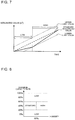
Fig. 7 is a diagram for explaining a recovery control operation of insufficient ventilation by the air-conditioning ventilation system according toEmbodiment 1 of the present invention. InFig. 7 , the horizontal axis represents time, and the vertical axis represents the integrated value [m3]. InFig. 7 , changes in the integrated value are indicated by the solid line. The standard integrated value is indicated by the thick dashed line, and the upper limit value and the lower limit value of the standard ventilation range are indicated by the thin dashed lines. - As illustrated in
Fig. 7 , when the ventilation rate is maintained at "low", the integrated value deviates from standard integrated value toward the lower limit value. When the integrated value reaches the lower limit value, the ventilation rate changes from "low" to "high", and the integrated value increases to reach the standard integrated value. - Although the cooling operation has been described, similar control is performed in the case of a heating operation.
- As described above, according to the air-conditioning ventilation system of
Embodiment 1, normal control is performed that causes theventilation device 3 to operate at a ventilation rate corresponding to the air-conditioning capacity of the air-conditioning apparatus 2. Thecontroller 4 performs recovery control of the ventilation amount that controls the ventilation rate of theventilation device 3 such that the integrated value of the amount of ventilation for a time duration from activation of theventilation device 3 under the normal control falls within a standard ventilation range including the standard integrated value. In this manner, it is possible to maintain an appropriate amount of ventilation during operation. Note that the ventilation rate of "standard" may be appropriately set according to the actual use conditions or other conditions. For example, as described above, the ventilation rate of "standard" may be set based on the ventilation rate for securing the amount of ventilation corresponding to half the indoor capacity in one hour, or may be set based on the progress of contamination indoors. - In
Embodiment 1, when the integrated value becomes equal to the lower limit value of the standard ventilation range, thecontroller 4 increases the ventilation rate of theventilation device 3 such that the integrated value becomes equal to the standard integrated value. This makes it possible to avoid insufficient ventilation. - In
Embodiment 1, theventilation device 3 is configured such that the ventilation rate is adjustable in at least three levels including low, standard, and high. Thecontroller 4 sets the ventilation rate of theventilation device 3 under the normal control to "standard" when the air-conditioning capacity of the air-conditioning apparatus 2 is intermediate, and sets the ventilation rate of theventilation device 3 under the normal control to "low" when the air-conditioning capacity is low or high. In this manner, when the air-conditioning capacity is high, the indoor temperature can quickly be brought close to the setting temperature by a reduction in ventilation rate. Also, when the air-conditioning capacity is low, the indoor temperature can be stabilized by a reduction in ventilation rate. - In
Embodiment 1, the ventilation rate of theventilation device 3 is controlled based on the maximum capacity rate. Meanwhile, inEmbodiment 2, theventilation device 3 is controlled using the humidity in the air-conditionedspace 1 in addition to the maximum capacity rate during a cooling operation, and is controlled using the refrigerant temperature in addition to the maximum capacity rate during a heating operation. In the following, the differences ofEmbodiment 2 fromEmbodiment 1 will be mainly described. - The configuration of the air-conditioning ventilation system is the same as that of
Embodiment 1 illustrated inFig. 1 . - In
Embodiment 1, the air-conditioning apparatus 2 obtains the actual air-conditioning capacity of the air-conditioning apparatus 2, and transmits the obtained air-conditioning capacity to thecontroller 4. InEmbodiment 2, the air-conditioning apparatus 2 transmits the humidity measured by thehumidity sensor 12 and the refrigerant temperature measured by thetemperature sensor 10 to thecontroller 4, in addition to the air-conditioning capacity. - During a cooling operation, the air-
conditioning apparatus 2 performs control for increasing the air-conditioning capacity when the cooling load is high. Thus, the temperature of the refrigerant flowing through the heat exchanger 7 decreases, so that the air-conditionedspace 1 is dehumidified. However, if the cooling load is excessively low, control for increasing the air-conditioning capacity is not performed, so that dehumidification cannot be performed. As a result, the comfort level of the humidity environment in the air-conditionedspace 1 is reduced. In consideration of this, inEmbodiment 2, the ventilation rate of theventilation device 3 is controlled taking into account the humidity in the air-conditionedspace 1, thereby affecting the control of the air-conditioning capacity of the air-conditioning apparatus 2 and avoiding a situation where dehumidification cannot be performed. In the following, the details of the control will be described. -
Fig. 8 is a diagram for explaining ventilation rate control on the ventilation device during a cooling operation according toEmbodiment 1 of the present invention. InFig. 8 , the horizontal axis represents the humidity [%] of the air-conditionedspace 1, and the vertical axis represents the maximum capacity rate [%]. - When the maximum capacity rate is less than 20% or greater than 60%, the ventilation rate of the
ventilation device 3 is set to "low". When the maximum capacity rate is greater than or equal to 0% and less than or equal to 60%, the ventilation rate of theventilation device 3 is set based on whether the humidity is less than or equal to a preset humidity. In this example, the preset humidity is 60%. Accordingly, the ventilation rate is set to "standard" when the humidity is less than or equal to 60%, and is set to "high" when the humidity is greater than 60%. -
Fig. 9 is a flowchart illustrating a ventilation rate control operation of the ventilation device during a cooling operation according toEmbodiment 2 of the present invention. - When the operation starts, the
controller 4 sets the ventilation rate of theventilation device 3 to "standard", and starts ventilation (step S11). Then, thecontroller 4 determines the ventilation rate based on the air-conditioning capacity and the humidity received from the air-conditioning apparatus 2 to control the ventilation device 3 (steps S12 to S17). Specifically, thecontroller 4 calculates the maximum capacity rate based on the air-conditioning capacity received from the air-conditioning apparatus 2, and determines whether the maximum capacity rate is less than or equal to 20% or greater than or equal to 60% (step S12). - If the maximum capacity rate is not less than or equal to 20% nor greater than or equal to 60% (No in step S12), then the
controller 4 determines whether the humidity measured by thehumidity sensor 12 is greater than 60% (step S13). If the humidity is not greater than 60% (No in step S13), then thecontroller 4 determines whether the integrated value is zero (step S14). The integrated value is supposed to be set to zero when starting the operation. If the integrated value is zero (Yes in step S14), the process returns to step S11, in which theventilation device 3 continues to ventilate at "standard". In this manner, it is possible to stabilize the indoor temperature while securing the required amount of ventilation. If the integrated value is not zero (No in step S14), the calculation of the integrated value has already been started in step S18 described below, and therefore thecontroller 4 sets the ventilation rate back to "standard" (step S17). - Meanwhile, if the maximum capacity rate is less than or equal to 20% or greater than or equal to 60% (Yes in step S12), the
controller 4 changes the ventilation rate of theventilation device 3 from "standard" to "low" (step S15). In this step, if the maximum capacity rate is greater than or equal to 60%, the air-conditioning capacity of the air-conditioning apparatus 2 is high. Accordingly, it becomes possible to quickly form a comfortable cool environment, by changing the amount of ventilation of theventilation device 3 from "standard" to "low" to reduce the amount of outdoor air to be suctioned. If the maximum capacity rate is less than or equal to 20%, the air-conditioning capacity of the air-conditioning apparatus 2 is low. Accordingly, it becomes possible to reduce variation in the indoor temperature by reducing the amount of outdoor air to be suctioned. - Meanwhile, if the maximum capacity rate is not less than or equal to 20% nor greater than or equal to 60% (No in step S12) and the humidity is high and greater than 60%, the
controller 4 changes the ventilation rate of theventilation device 3 from "standard" to "high" (step S16) to increase the amount of outdoor air to be suctioned. As the amount of suctioned outdoor air is increased, the indoor temperature temporarily increases. Therefore, the temperature difference ΔT increases, which affects the control of the air-conditioning capacity described with reference toFigs. 3 and 4 . As a result, the air-conditioning apparatus 2 performs control for increasing the air-conditioning capacity. As the control for increasing the air-conditioning capacity is performed, the refrigerant temperature of the heat exchanger 7 decreases. Therefore, the amount of dehumidification by the air-conditioning apparatus 2 increases, so that the humidity in the indoor air is reduced. In this manner, since the ventilation rate is controlled taking into account the humidity, it is possible to avoid a situation where dehumidification cannot be performed due to an excessively low cooling load, and provide a more comfortable low-humidity environment. - After the ventilation rate is changed to "low" or "high" in the manner described above, if this setting is maintained for a long period of time, the following problem occurs. Specifically, if the ventilation rate continues to be set at "low" for a long period of time, the required amount of ventilation cannot be secured. Meanwhile, if the ventilation rate continues to be set at "high" for a long period of time, the amount of suctioned outdoor air is increased, resulting in excess ventilation. In the case of excess ventilation, an excessive air conditioning load needs to be processed, so that the power consumption is increased. To solve this problem, in
Embodiment 2, recovery control of the amount of ventilation is performed to avoid insufficient ventilation and excess ventilation. - In the recovery control, the following steps S18 to S24 are performed such that the integrated value of the amount of ventilation for a time duration t from when the ventilation rate is set to "low" or "high" in step S15 or S17 falls within the standard ventilation range.
- After the ventilation rate is set to "low" or "high" in step S15 or S17, the
controller 4 starts a calculation of the integrated value (step S18). After continuing the operation at the ventilation rate "high" or "low", thecontroller 4 determines whether the integrated value is equal to the upper limit value or the lower limit value of the standard ventilation range (step S19). If the integrated value is not equal to the upper limit value or the lower limit value (No in step S19), the process returns to step S12. Then, thecontroller 4 performs the operations described above. That is, once thecontroller 4 starts a calculation of the integrated value, thecontroller 4 controls the ventilation rate based on the maximum capacity rate and the humidity (steps S12 to S17) and continues to calculate the integrated value (step S18) until the integrated value becomes equal to the upper limit value or the lower limit value. - Then, if the integrated value becomes equal to the lower limit value of the standard ventilation range (Yes in step S20), the
controller 4 forcibly changes the amount of ventilation of theventilation device 3 to "high" (step S21). That is, if the integrated value becomes equal to the lower limit value after setting the ventilation rate to "low" in step S3 and continuing the operation, in other words, if the integrated value is about to be out of the standard ventilation range, thecontroller 4 changes the ventilation rate from "low" to "high" to bring back the integrated value of the ventilation amount of the air-conditionedspace 1 to the standard integrated value. In this manner, the ventilation rate is increased to increase the amount of outdoor air to be suctioned, thereby preventing insufficient ventilation. - Meanwhile, if the integrated value becomes equal to the upper limit value (No in step S20) after setting the ventilation rate to "high" in step S16 and continuing the operation, in other words, if the integrated value is about to be out of the standard ventilation range, the
controller 4 changes the ventilation rate from "high" to "low" to bring back the integrated value of the ventilation amount of the air-conditionedspace 1 to the standard integrated value (Step S22). In this manner, the ventilation rate is reduced to reduce the amount of outdoor air to be suctioned, thereby minimizing the increase in indoor temperature due to suction of outdoor air and minimizing the increase in air conditioning load. - If the integrated value becomes equal to the standard integrated value (step S23) after setting the ventilation rate to "high" or "low" in step S21 or S22 and continuing the operation, the
controller 4 resets the integrated value (step S24). Then, the process returns to step S11, in which thecontroller 4 sets the ventilation rate back to "standard". - With the above operation, it is possible to perform ventilation continuously 24 hours while preventing an unacceptable level of insufficient ventilation or excess ventilation.
-
Fig. 10 is a diagram for explaining a recovery control operation of the amount of ventilation by the air-conditioning ventilation system according toEmbodiment 2 of the present invention. InFig. 10 , the horizontal axis represents time, and the vertical axis represents the integrated value [m3]. InFig. 10 , changes in the integrated value are indicated by the solid line. The standard integrated value is indicated by the thick dashed line, and the upper limit value and the lower limit value of the standard ventilation range are indicated by the thin dashed lines. - As illustrated in
Fig. 10 , when the ventilation rate is maintained at "high", the integrated value deviates from standard integrated value toward the upper limit value. When the integrated value reaches the upper limit value, the ventilation rate changes from "high" to "low", and the integrated value decreases to reach the standard integrated value. The recovery control operation performed by maintaining the ventilation rate at "low" is the same as that ofFig. 7 inEmbodiment 1. - The following describes operations during a heating operation.
- During a heating operation, if the outdoor air temperature is high, the temperature of the air blown out of the air-
conditioning apparatus 2 into the air-conditioned space 1 (hereinafter referred to as a blown-out temperature) is stabilized at low temperature. If the outdoor air temperature is low, the blown-out temperature is stabilized at high temperature. When the blown-out temperature is stabilized at low temperature, it means that the temperature of the refrigerant flowing through the heat exchanger 7 is low. If the refrigerant temperature becomes lower than the setting refrigerant temperature (for example, 40 degrees), the blown-out temperature decreases. This gives a feeling of cold air to the user even though a heating operation is performed. In consideration of this, inEmbodiment 2, the ventilation rate of theventilation device 3 is controlled based on the refrigerant temperature, thereby affecting the control of the air-conditioning capacity of the air-conditioning apparatus 2 and reducing a feeling of cold air when the outdoor air temperature is high. In the following, the details of the control will be described. -
Fig. 11 is a diagram for explaining ventilation rate control on the ventilation device during a heating operation according toEmbodiment 2 of the present invention. InFig. 11 , the horizontal axis represents the refrigerant temperature [degree], and the vertical axis represents the maximum capacity rate [%]. - When the maximum capacity rate is less than 20% or greater than 60%, the ventilation rate of the
ventilation device 3 is set to "low". When the maximum capacity rate is greater than or equal to 0% and less than or equal to 60%, the ventilation rate of theventilation device 3 is set based on whether the refrigerant temperature is lower than or equal to a setting refrigerant temperature. In this example, the setting refrigerant temperature is 40 degrees. Accordingly, the ventilation rate is set to "high" when the refrigerant temperature is lower than or equal to 40 degrees, and is set to "standard" when the refrigerant temperature is higher than 40 degrees. -
Fig. 12 is a flowchart illustrating a ventilation rate control operation of the ventilation device during a heating operation according toEmbodiment 2 of the present invention. The flowchart ofFig. 12 differs from the flowchart of a cooling operation illustrated inFig. 9 only in steps S13a, S16a, and S17a. In the following, the steps different from those ofFig. 9 will be mainly described. - When the maximum capacity rate is greater than 20% and less than 60% (No in step S12), the indoor environment is becoming stable. Then, if the refrigerant temperature is higher than 40 degrees (Yes in Step S13a), the
controller 4 causes theventilation device 3 to operate while maintaining the ventilation rate at "standard" (step S16a). Meanwhile, if the refrigerant temperature is lower than or equal to 40 degrees (No in step S13a), the blown-out air of the air-conditioning apparatus 2 gives a greater feeling of cold air, so that the indoor environment deteriorates. Accordingly, thecontroller 4 changes the ventilation rate of theventilation device 3 from "standard" to "high" (step S17a) to reduce the amount of outdoor air to be suctioned, thereby temporarily reducing the indoor temperature. As the indoor temperature decreases, the temperature difference ΔT increases. Accordingly, the air-conditioning apparatus 2 performs an operation that increases the air-conditioning capacity. As a result, the refrigerant temperature increases, thereby reducing a feeling of cold air due to the airflow blown out of the air-conditioning apparatus 2. - As described above, according to
Embodiment 2, it is possible to avoid a situation where the amount of ventilation is insufficient as inEmbodiment 1. Further, inEmbodiment 2, when the integrated value of the ventilation amount from activation of theventilation device 3 under the normal control becomes equal to the upper limit value of the standard ventilation range, thecontroller 4 reduces the ventilation rate of theventilation device 3 such that the integrated value becomes equal to the standard integrated value. This makes it possible to avoid insufficient ventilation. - In
Embodiment 2, thecontroller 4 causes theventilation device 3 to operate at a ventilation rate corresponding to the air-conditioning capacity of the air-conditioning apparatus 2 and the humidity in the air-conditionedspace 1, under normal control during a cooling operation. In this manner, since the ventilation rate can be controlled taking into account the humidity in the air-conditionedspace 1 in addition to the air-conditioning capacity, it is possible to provide a comfortable low-humidity environment. - The
ventilation device 3 is configured such that the ventilation rate is adjustable in at least three levels including low, standard, and high. Thecontroller 4 sets the ventilation rate of theventilation device 3 under the normal control during a cooling operation to any of the following (1) to (3). - (1) When the air-conditioning capacity of the air-
conditioning apparatus 2 is intermediate and the humidity in the air-conditionedspace 1 is less than or equal to the preset humidity, the ventilation rate is set to "standard". - (2) When the air-conditioning capacity of the air-
conditioning apparatus 2 is intermediate and the humidity in the air-conditionedspace 1 is greater than the preset humidity, the ventilation rate is set to "high". - (3) When the air-conditioning capacity of the air-
conditioning apparatus 2 is low or high, the ventilation rate is set to "low". - In this manner, it is possible to control the ventilation rate based on the air-conditioning capacity, and improve the dehumidification effect of the air-
conditioning apparatus 2 by increasing the ventilation rate under high-humidity conditions during a cooling operation. - In
Embodiment 2, thecontroller 4 causes theventilation device 3 to operate at a ventilation rate corresponding to the air-conditioning capacity of the air-conditioning apparatus 2 and the temperature of the refrigerant flowing through the heat exchanger 7 of the air-conditioning apparatus 2, under normal control during a heating operation. In this manner, since the ventilation rate can be controlled taking into account the refrigerant temperature in addition to the air-conditioning capacity, it is possible to reduce a feeling of cold air due to the airflow blown out of the air-conditioning apparatus 2. - The
controller 4 sets the ventilation rate of theventilation device 3 under the normal control during a heating operation to any of the following (1) to (3). - (1) When the air-conditioning capacity of the air-
conditioning apparatus 2 is intermediate and the temperature of the refrigerant flowing through the heat exchanger 7 of the air-conditioning apparatus 2 is lower than or equal to the setting refrigerant temperature, the ventilation rate is set to "high". - (2) When the air-conditioning capacity of the air-
conditioning apparatus 2 is intermediate and the temperature of the refrigerant flowing through the heat exchanger 7 of the air-conditioning apparatus 2 is higher than the setting refrigerant temperature, the ventilation rate is set to "standard". - (3) When the air-conditioning capacity of the air-
conditioning apparatus 2 is low or high, the ventilation rate is set to "low". - In this manner, it is possible to control the ventilation rate based on the air-conditioning capacity. Further, under the condition where the uncomfortable feeling due to cold air during a heating operation is increased, it is possible to increase the temperature of the blown-out air of the air-
conditioning apparatus 2 by increasing the ventilation rate, and avoid giving a feeling of cold air to the user. - In the above Embodiments 1 and 2, specific values such as the thresholds for dividing the maximum capacity rate into three levels, the preset humidity, and the setting refrigerant temperature are merely examples, and may be appropriately set according to the actual use conditions or other conditions.
- As for the air-conditioning ventilation system, the following modification may be made to the configuration illustrated in
Fig. 1 . Even in such a case, it is possible to obtain the same effects. -
Fig. 13 is a diagram illustrating a modification of the air-conditioning ventilation systems according toEmbodiments - As illustrated in
Fig. 13 , theventilation device 3 includes threeventilation units 3a, and is configured to change the ventilation rate by changing the number ofventilation units 3a to be activated. Specifically, oneventilation unit 3a may be activated when the ventilation rate is "low"; twoventilation units 3a may be activated when the ventilation rate is "high"; and threeventilation units 3a may be activated when the ventilation rate is "high". Note that although there are threeventilation units 3a in this example, the number ofventilation units 3a is not limited to three. - 1 air-conditioned
space 2 air-conditioningapparatus 2a casing 3ventilation device 4controller 5air inlet 6 circulation fan 7heat exchanger 8air outlet 9temperature sensor 10temperature sensor 11temperature sensor 12humidity sensor 13exhaust fan 14 air-supply fan
Claims (9)
- An air-conditioning ventilation system comprising:a ventilation device configured to ventilate an air-conditioned space while controlling a ventilation rate;an air-conditioning apparatus including a heat exchanger configured to exchange heat between refrigerant and air, the air-conditioning apparatus being configured to operate while controlling an air-conditioning capacity thereof to bring an indoor temperature in the air-conditioned space to a setting temperature; anda controller configured to performnormal control that causes the ventilation device to operate to ventilate the air-conditioned space at a ventilation rate corresponding to the air-conditioning capacity of the air-conditioning apparatus, andrecovery control that controls the ventilation rate of the ventilation device such that an integrated value of an amount of ventilation for a time duration from activation of the ventilation device under the normal control falls within a standard ventilation range including a standard integrated value of an amount of ventilation obtained by causing the ventilation device to operate to ventilate the air-conditioned space at a standard ventilation rate for a time duration having a same length as the time duration.
- The air-conditioning ventilation system of claim 1, wherein when the integrated value becomes equal to a lower limit value of the standard ventilation range, the controller increases the ventilation rate of the ventilation device such that the integrated value becomes equal to the standard integrated value, under the recovery control.
- The air-conditioning ventilation system of claim 1 or 2, wherein when the integrated value becomes equal to an upper limit value of the standard ventilation range, the controller reduces the ventilation rate of the ventilation device such that the integrated value becomes equal to the standard integrated value, under the recovery control.
- The air-conditioning ventilation system of any one of claims 1 to 3, wherein the controller causes the ventilation device to operate at a ventilation rate corresponding to the air-conditioning capacity of the air-conditioning apparatus and a humidity in the air-conditioned space, under the normal control during a cooling operation.
- The air-conditioning ventilation system of any one of claims 1 to 4, wherein the controller causes the ventilation device to operate at a ventilation rate corresponding to the air-conditioning capacity of the air-conditioning apparatus and a temperature of the refrigerant flowing through the heat exchanger of the air-conditioning apparatus, under the normal control during a heating operation.
- The air-conditioning ventilation system of claim 1 or 2, wherein:the ventilation device is configured such that the ventilation rate is adjustable in at least three levels including the standard, high that is higher than the standard, and low that is lower than the standard;when the air-conditioning capacity of the air-conditioning apparatus is intermediate, the controller sets the ventilation rate of the ventilation device under the normal control to the standard; andwhen the air-conditioning capacity of the air-conditioning apparatus is low or high, the controller sets the ventilation rate of the ventilation device under the normal control to the low.
- The air-conditioning ventilation system of any one of claims 1 to 4, wherein:the ventilation device is configured such that the ventilation rate is adjustable in at least three levels including the standard, high that is higher than the standard, and low that is lower than the standard;when the air-conditioning capacity of the air-conditioning apparatus is intermediate and a humidity in the air-conditioned space is higher than a preset humidity, the controller sets the ventilation rate of the ventilation device under the normal control during a cooling operation to the high;when the air-conditioning capacity is intermediate and the humidity in the air-conditioned space is lower than or equal to the preset humidity, the controller sets the ventilation rate of the ventilation device under the normal control during a cooling operation to the standard; andwhen the air-conditioning capacity is low or high, the controller sets the ventilation rate of the ventilation device under the normal control during a cooling operation to the low.
- The air-conditioning ventilation system of any one of claims 1 to 3 and 5 wherein:the ventilation device is configured such that the ventilation rate is adjustable in at least three levels including the standard, high that is higher than the standard, and low that is lower than the standard;when the air-conditioning capacity of the air-conditioning apparatus is intermediate and a temperature of the refrigerant flowing through the heat exchanger of the air-conditioning apparatus is lower than or equal to a setting refrigerant temperature, the controller sets the ventilation rate of the ventilation device under the normal control during a heating operation to the high;when the air-conditioning capacity of the air-conditioning apparatus is intermediate and the temperature of the refrigerant flowing through the heat exchanger of the air-conditioning apparatus is higher than the setting refrigerant temperature, the controller sets the ventilation rate of the ventilation device under the normal control during a heating operation to the standard; andwhen the air-conditioning capacity of the air-conditioning apparatus is low or high, the controller sets the ventilation rate of the ventilation device under the normal control during a heating operation to the low.
- The air-conditioning ventilation system of any one of claims 1 to 8, wherein the ventilation device includes a plurality of ventilation units, and is configured to control the ventilation rate by changing the number of ventilation units to be activated.
Applications Claiming Priority (1)
| Application Number | Priority Date | Filing Date | Title |
|---|---|---|---|
| PCT/JP2019/000512 WO2020144808A1 (en) | 2019-01-10 | 2019-01-10 | Air conditioning and ventilation system |
Publications (3)
| Publication Number | Publication Date |
|---|---|
| EP3910256A1 true EP3910256A1 (en) | 2021-11-17 |
| EP3910256A4 EP3910256A4 (en) | 2022-01-19 |
| EP3910256B1 EP3910256B1 (en) | 2023-11-22 |
Family
ID=71521582
Family Applications (1)
| Application Number | Title | Priority Date | Filing Date |
|---|---|---|---|
| EP19909600.9A Active EP3910256B1 (en) | 2019-01-10 | 2019-01-10 | Air conditioning and ventilation system |
Country Status (5)
| Country | Link |
|---|---|
| US (1) | US11879658B2 (en) |
| EP (1) | EP3910256B1 (en) |
| JP (1) | JP7012885B2 (en) |
| CN (1) | CN113260818A (en) |
| WO (1) | WO2020144808A1 (en) |
Families Citing this family (5)
| Publication number | Priority date | Publication date | Assignee | Title |
|---|---|---|---|---|
| CN113692515B (en) * | 2019-04-15 | 2023-02-17 | 大金工业株式会社 | Air conditioning system |
| US20220228756A1 (en) * | 2021-01-14 | 2022-07-21 | Honeywell International Inc. | Dynamic ventilation control for a building |
| JP7041988B1 (en) * | 2021-09-13 | 2022-03-25 | 株式会社から屋 | Natural ventilation and forced ventilation combined building |
| CN114396717B (en) * | 2022-02-08 | 2023-03-14 | 珠海格力电器股份有限公司 | Fresh air conditioner control method and device, fresh air conditioner, system and storage medium |
| CN114467763B (en) * | 2022-04-18 | 2022-07-08 | 大牧人机械(胶州)有限公司 | Self-adaptive control method for different types of permanent magnet fans of pig house |
Family Cites Families (15)
| Publication number | Priority date | Publication date | Assignee | Title |
|---|---|---|---|---|
| JP2000291997A (en) * | 1999-04-02 | 2000-10-20 | Mitsubishi Electric Corp | Air conditioner with ventilating function |
| FR2839144B1 (en) * | 2002-04-25 | 2004-12-17 | Conseils Etudes Et Recherches En Gestion De Lair Cerga | METHOD FOR CONTROLLING THE VENTILATION FLOW OF A PREMISES AND DEVICE |
| JP4239675B2 (en) * | 2003-05-15 | 2009-03-18 | マックス株式会社 | Ventilation equipment |
| JP2005098571A (en) | 2003-09-24 | 2005-04-14 | Matsushita Electric Ind Co Ltd | Ventilation central control system |
| US7222494B2 (en) * | 2004-01-07 | 2007-05-29 | Honeywell International Inc. | Adaptive intelligent circulation control methods and systems |
| US7827813B2 (en) * | 2007-01-30 | 2010-11-09 | Johnson Controls Technology Company | Adaptive real-time optimization control |
| JP2012017868A (en) * | 2010-07-06 | 2012-01-26 | Panasonic Corp | Total heat exchange type ventilation apparatus |
| US9322568B2 (en) * | 2010-10-07 | 2016-04-26 | Field Controls, Llc | Whole house ventilation system |
| US9810462B2 (en) * | 2011-12-21 | 2017-11-07 | Lennox Industries Inc. | Dehumidification using intermittent ventilation |
| US9874360B2 (en) * | 2013-05-14 | 2018-01-23 | Mitsubishi Electric Corporation | Air-conditioning system |
| WO2017127431A1 (en) * | 2016-01-18 | 2017-07-27 | Tempo, Inc. | Fresh air building and home ventilation apparatus and methodologies |
| CN107883534A (en) * | 2016-09-23 | 2018-04-06 | 江苏科技大学 | A kind of wall-mounted air purification device and its control method based on hot recycling |
| KR101998640B1 (en) * | 2017-04-21 | 2019-10-02 | 한국에너지기술연구원 | Ventilation system and ventilation method for controlling ventilation path |
| CN107883531B (en) * | 2017-10-02 | 2020-08-14 | 广东美的制冷设备有限公司 | Fresh air fan and air conditioner linkage system, control method and device thereof, and storage medium |
| CN108317616A (en) * | 2018-05-11 | 2018-07-24 | 张忠 | A kind of fresh air conditioner all-in-one machine |
-
2019
- 2019-01-10 EP EP19909600.9A patent/EP3910256B1/en active Active
- 2019-01-10 CN CN201980087497.6A patent/CN113260818A/en active Pending
- 2019-01-10 JP JP2020565105A patent/JP7012885B2/en active Active
- 2019-01-10 US US17/288,217 patent/US11879658B2/en active Active
- 2019-01-10 WO PCT/JP2019/000512 patent/WO2020144808A1/en unknown
Also Published As
| Publication number | Publication date |
|---|---|
| WO2020144808A1 (en) | 2020-07-16 |
| JPWO2020144808A1 (en) | 2021-09-09 |
| EP3910256B1 (en) | 2023-11-22 |
| US20210404695A1 (en) | 2021-12-30 |
| EP3910256A4 (en) | 2022-01-19 |
| JP7012885B2 (en) | 2022-01-28 |
| US11879658B2 (en) | 2024-01-23 |
| CN113260818A (en) | 2021-08-13 |
Similar Documents
| Publication | Publication Date | Title |
|---|---|---|
| EP3910256B1 (en) | Air conditioning and ventilation system | |
| WO2019095561A1 (en) | Air conditioner control method, apparatus, and air conditioner | |
| US10753664B2 (en) | Method and apparatus for reheat dehumidification with variable speed outdoor fan | |
| CN107525217B (en) | Air conditioner control method and device and air conditioner | |
| CN108644968B (en) | Control method for air conditioning system | |
| CN112283893B (en) | Method and device for controlling air conditioner and air conditioner | |
| CN110567137B (en) | Air conditioner and air supply control method thereof | |
| CN105387578A (en) | Air-conditioning system and control method and system thereof | |
| CN108709297A (en) | Air conditioning control method and control device | |
| CN108826599B (en) | Control method for air conditioning system | |
| CN108592353B (en) | Control method for air conditioning system | |
| WO2021175013A1 (en) | Air conditioner and control method thereof | |
| EP3255353B1 (en) | Method and apparatus for optimizing latent capacity of a variable speed compressor system | |
| JP2018173206A (en) | Vav unit control device and control method for vav unit | |
| CN111043737A (en) | Method and device for controlling expansion valve and air conditioner | |
| CN109458709B (en) | Air humidity adjusting device and control method | |
| JP2636514B2 (en) | Air conditioner | |
| CN114110921B (en) | Method and device for detecting installation state of temperature sensing bulb, air conditioner of air duct machine and medium | |
| CN114322235A (en) | Method and device for controlling condensation prevention of air conditioner and air conditioner | |
| CN113757953A (en) | Control method of comfortable multi-split air conditioner | |
| WO2018211612A1 (en) | Air conditioning device | |
| US10969145B2 (en) | Method and apparatus for hybrid dehumidification | |
| JP2563549B2 (en) | Air conditioner operation control method | |
| JPH1030839A (en) | Air conditioner | |
| JP2000154931A (en) | Unit for computing set value of supply air temperature for air conditioner |
Legal Events
| Date | Code | Title | Description |
|---|---|---|---|
| STAA | Information on the status of an ep patent application or granted ep patent |
Free format text: STATUS: THE INTERNATIONAL PUBLICATION HAS BEEN MADE |
|
| PUAI | Public reference made under article 153(3) epc to a published international application that has entered the european phase |
Free format text: ORIGINAL CODE: 0009012 |
|
| STAA | Information on the status of an ep patent application or granted ep patent |
Free format text: STATUS: REQUEST FOR EXAMINATION WAS MADE |
|
| 17P | Request for examination filed |
Effective date: 20210702 |
|
| AK | Designated contracting states |
Kind code of ref document: A1 Designated state(s): AL AT BE BG CH CY CZ DE DK EE ES FI FR GB GR HR HU IE IS IT LI LT LU LV MC MK MT NL NO PL PT RO RS SE SI SK SM TR |
|
| A4 | Supplementary search report drawn up and despatched |
Effective date: 20211222 |
|
| RIC1 | Information provided on ipc code assigned before grant |
Ipc: F24F 140/50 20180101ALN20211216BHEP Ipc: F24F 11/00 20180101ALN20211216BHEP Ipc: F24F 11/74 20180101ALI20211216BHEP Ipc: F24F 7/007 20060101AFI20211216BHEP |
|
| DAV | Request for validation of the european patent (deleted) | ||
| DAX | Request for extension of the european patent (deleted) | ||
| GRAP | Despatch of communication of intention to grant a patent |
Free format text: ORIGINAL CODE: EPIDOSNIGR1 |
|
| STAA | Information on the status of an ep patent application or granted ep patent |
Free format text: STATUS: GRANT OF PATENT IS INTENDED |
|
| RIC1 | Information provided on ipc code assigned before grant |
Ipc: F24F 140/50 20180101ALN20230519BHEP Ipc: F24F 11/00 20180101ALN20230519BHEP Ipc: F24F 11/74 20180101ALI20230519BHEP Ipc: F24F 7/007 20060101AFI20230519BHEP |
|
| INTG | Intention to grant announced |
Effective date: 20230613 |
|
| GRAS | Grant fee paid |
Free format text: ORIGINAL CODE: EPIDOSNIGR3 |
|
| GRAA | (expected) grant |
Free format text: ORIGINAL CODE: 0009210 |
|
| STAA | Information on the status of an ep patent application or granted ep patent |
Free format text: STATUS: THE PATENT HAS BEEN GRANTED |
|
| P01 | Opt-out of the competence of the unified patent court (upc) registered |
Effective date: 20231006 |
|
| AK | Designated contracting states |
Kind code of ref document: B1 Designated state(s): AL AT BE BG CH CY CZ DE DK EE ES FI FR GB GR HR HU IE IS IT LI LT LU LV MC MK MT NL NO PL PT RO RS SE SI SK SM TR |
|
| REG | Reference to a national code |
Ref country code: GB Ref legal event code: FG4D |
|
| REG | Reference to a national code |
Ref country code: CH Ref legal event code: EP Ref country code: DE Ref legal event code: R096 Ref document number: 602019042113 Country of ref document: DE |
|
| REG | Reference to a national code |
Ref country code: IE Ref legal event code: FG4D |
|
| REG | Reference to a national code |
Ref country code: SE Ref legal event code: TRGR |
|
| PGFP | Annual fee paid to national office [announced via postgrant information from national office to epo] |
Ref country code: GB Payment date: 20231221 Year of fee payment: 6 |
|
| PGFP | Annual fee paid to national office [announced via postgrant information from national office to epo] |
Ref country code: SE Payment date: 20231228 Year of fee payment: 6 Ref country code: FR Payment date: 20231222 Year of fee payment: 6 |
|
| REG | Reference to a national code |
Ref country code: LT Ref legal event code: MG9D |
|
| REG | Reference to a national code |
Ref country code: NL Ref legal event code: MP Effective date: 20231122 |
|
| PG25 | Lapsed in a contracting state [announced via postgrant information from national office to epo] |
Ref country code: GR Free format text: LAPSE BECAUSE OF FAILURE TO SUBMIT A TRANSLATION OF THE DESCRIPTION OR TO PAY THE FEE WITHIN THE PRESCRIBED TIME-LIMIT Effective date: 20240223 |
|
| PG25 | Lapsed in a contracting state [announced via postgrant information from national office to epo] |
Ref country code: IS Free format text: LAPSE BECAUSE OF FAILURE TO SUBMIT A TRANSLATION OF THE DESCRIPTION OR TO PAY THE FEE WITHIN THE PRESCRIBED TIME-LIMIT Effective date: 20240322 |
|
| PG25 | Lapsed in a contracting state [announced via postgrant information from national office to epo] |
Ref country code: LT Free format text: LAPSE BECAUSE OF FAILURE TO SUBMIT A TRANSLATION OF THE DESCRIPTION OR TO PAY THE FEE WITHIN THE PRESCRIBED TIME-LIMIT Effective date: 20231122 |
|
| REG | Reference to a national code |
Ref country code: AT Ref legal event code: MK05 Ref document number: 1634167 Country of ref document: AT Kind code of ref document: T Effective date: 20231122 |
|
| PG25 | Lapsed in a contracting state [announced via postgrant information from national office to epo] |
Ref country code: NL Free format text: LAPSE BECAUSE OF FAILURE TO SUBMIT A TRANSLATION OF THE DESCRIPTION OR TO PAY THE FEE WITHIN THE PRESCRIBED TIME-LIMIT Effective date: 20231122 |
|
| PGFP | Annual fee paid to national office [announced via postgrant information from national office to epo] |
Ref country code: ES Payment date: 20240202 Year of fee payment: 6 |