EP3910231B1 - Système de sécurité - Google Patents
Système de sécurité Download PDFInfo
- Publication number
- EP3910231B1 EP3910231B1 EP21168060.8A EP21168060A EP3910231B1 EP 3910231 B1 EP3910231 B1 EP 3910231B1 EP 21168060 A EP21168060 A EP 21168060A EP 3910231 B1 EP3910231 B1 EP 3910231B1
- Authority
- EP
- European Patent Office
- Prior art keywords
- person
- radio
- identification
- data
- safety
- Prior art date
- Legal status (The legal status is an assumption and is not a legal conclusion. Google has not performed a legal analysis and makes no representation as to the accuracy of the status listed.)
- Active
Links
- 238000011156 evaluation Methods 0.000 claims description 53
- 238000000034 method Methods 0.000 claims description 7
- 230000004807 localization Effects 0.000 claims description 5
- 230000005540 biological transmission Effects 0.000 claims description 3
- 238000013459 approach Methods 0.000 claims description 2
- 238000011161 development Methods 0.000 description 11
- 238000001514 detection method Methods 0.000 description 7
- 231100001261 hazardous Toxicity 0.000 description 7
- 238000010200 validation analysis Methods 0.000 description 7
- 238000004519 manufacturing process Methods 0.000 description 6
- 238000005516 engineering process Methods 0.000 description 5
- 230000008901 benefit Effects 0.000 description 4
- 230000008569 process Effects 0.000 description 3
- 238000012545 processing Methods 0.000 description 3
- 230000009471 action Effects 0.000 description 2
- 238000013475 authorization Methods 0.000 description 2
- 230000000295 complement effect Effects 0.000 description 2
- 230000007613 environmental effect Effects 0.000 description 2
- 239000000463 material Substances 0.000 description 2
- 239000011159 matrix material Substances 0.000 description 2
- 239000004065 semiconductor Substances 0.000 description 2
- 238000004891 communication Methods 0.000 description 1
- 239000000428 dust Substances 0.000 description 1
- 230000000694 effects Effects 0.000 description 1
- 239000000314 lubricant Substances 0.000 description 1
- 238000005259 measurement Methods 0.000 description 1
- 238000004377 microelectronic Methods 0.000 description 1
- 230000004719 natural immunity Effects 0.000 description 1
- 230000003287 optical effect Effects 0.000 description 1
- 238000005457 optimization Methods 0.000 description 1
- 230000005693 optoelectronics Effects 0.000 description 1
- 230000001681 protective effect Effects 0.000 description 1
- 230000009467 reduction Effects 0.000 description 1
- 230000004044 response Effects 0.000 description 1
- 239000007787 solid Substances 0.000 description 1
- 238000012360 testing method Methods 0.000 description 1
Images


Classifications
-
- H—ELECTRICITY
- H04—ELECTRIC COMMUNICATION TECHNIQUE
- H04W—WIRELESS COMMUNICATION NETWORKS
- H04W4/00—Services specially adapted for wireless communication networks; Facilities therefor
- H04W4/02—Services making use of location information
- H04W4/029—Location-based management or tracking services
-
- F—MECHANICAL ENGINEERING; LIGHTING; HEATING; WEAPONS; BLASTING
- F16—ENGINEERING ELEMENTS AND UNITS; GENERAL MEASURES FOR PRODUCING AND MAINTAINING EFFECTIVE FUNCTIONING OF MACHINES OR INSTALLATIONS; THERMAL INSULATION IN GENERAL
- F16P—SAFETY DEVICES IN GENERAL; SAFETY DEVICES FOR PRESSES
- F16P3/00—Safety devices acting in conjunction with the control or operation of a machine; Control arrangements requiring the simultaneous use of two or more parts of the body
- F16P3/12—Safety devices acting in conjunction with the control or operation of a machine; Control arrangements requiring the simultaneous use of two or more parts of the body with means, e.g. feelers, which in case of the presence of a body part of a person in or near the danger zone influence the control or operation of the machine
- F16P3/14—Safety devices acting in conjunction with the control or operation of a machine; Control arrangements requiring the simultaneous use of two or more parts of the body with means, e.g. feelers, which in case of the presence of a body part of a person in or near the danger zone influence the control or operation of the machine the means being photocells or other devices sensitive without mechanical contact
- F16P3/147—Safety devices acting in conjunction with the control or operation of a machine; Control arrangements requiring the simultaneous use of two or more parts of the body with means, e.g. feelers, which in case of the presence of a body part of a person in or near the danger zone influence the control or operation of the machine the means being photocells or other devices sensitive without mechanical contact using electro-magnetic technology, e.g. tags or radar
-
- F—MECHANICAL ENGINEERING; LIGHTING; HEATING; WEAPONS; BLASTING
- F16—ENGINEERING ELEMENTS AND UNITS; GENERAL MEASURES FOR PRODUCING AND MAINTAINING EFFECTIVE FUNCTIONING OF MACHINES OR INSTALLATIONS; THERMAL INSULATION IN GENERAL
- F16P—SAFETY DEVICES IN GENERAL; SAFETY DEVICES FOR PRESSES
- F16P3/00—Safety devices acting in conjunction with the control or operation of a machine; Control arrangements requiring the simultaneous use of two or more parts of the body
- F16P3/12—Safety devices acting in conjunction with the control or operation of a machine; Control arrangements requiring the simultaneous use of two or more parts of the body with means, e.g. feelers, which in case of the presence of a body part of a person in or near the danger zone influence the control or operation of the machine
- F16P3/14—Safety devices acting in conjunction with the control or operation of a machine; Control arrangements requiring the simultaneous use of two or more parts of the body with means, e.g. feelers, which in case of the presence of a body part of a person in or near the danger zone influence the control or operation of the machine the means being photocells or other devices sensitive without mechanical contact
- F16P3/142—Safety devices acting in conjunction with the control or operation of a machine; Control arrangements requiring the simultaneous use of two or more parts of the body with means, e.g. feelers, which in case of the presence of a body part of a person in or near the danger zone influence the control or operation of the machine the means being photocells or other devices sensitive without mechanical contact using image capturing devices
-
- F—MECHANICAL ENGINEERING; LIGHTING; HEATING; WEAPONS; BLASTING
- F16—ENGINEERING ELEMENTS AND UNITS; GENERAL MEASURES FOR PRODUCING AND MAINTAINING EFFECTIVE FUNCTIONING OF MACHINES OR INSTALLATIONS; THERMAL INSULATION IN GENERAL
- F16P—SAFETY DEVICES IN GENERAL; SAFETY DEVICES FOR PRESSES
- F16P3/00—Safety devices acting in conjunction with the control or operation of a machine; Control arrangements requiring the simultaneous use of two or more parts of the body
- F16P3/12—Safety devices acting in conjunction with the control or operation of a machine; Control arrangements requiring the simultaneous use of two or more parts of the body with means, e.g. feelers, which in case of the presence of a body part of a person in or near the danger zone influence the control or operation of the machine
- F16P3/14—Safety devices acting in conjunction with the control or operation of a machine; Control arrangements requiring the simultaneous use of two or more parts of the body with means, e.g. feelers, which in case of the presence of a body part of a person in or near the danger zone influence the control or operation of the machine the means being photocells or other devices sensitive without mechanical contact
- F16P3/144—Safety devices acting in conjunction with the control or operation of a machine; Control arrangements requiring the simultaneous use of two or more parts of the body with means, e.g. feelers, which in case of the presence of a body part of a person in or near the danger zone influence the control or operation of the machine the means being photocells or other devices sensitive without mechanical contact using light grids
-
- G—PHYSICS
- G06—COMPUTING; CALCULATING OR COUNTING
- G06K—GRAPHICAL DATA READING; PRESENTATION OF DATA; RECORD CARRIERS; HANDLING RECORD CARRIERS
- G06K7/00—Methods or arrangements for sensing record carriers, e.g. for reading patterns
- G06K7/10—Methods or arrangements for sensing record carriers, e.g. for reading patterns by electromagnetic radiation, e.g. optical sensing; by corpuscular radiation
- G06K7/10544—Methods or arrangements for sensing record carriers, e.g. for reading patterns by electromagnetic radiation, e.g. optical sensing; by corpuscular radiation by scanning of the records by radiation in the optical part of the electromagnetic spectrum
- G06K7/10821—Methods or arrangements for sensing record carriers, e.g. for reading patterns by electromagnetic radiation, e.g. optical sensing; by corpuscular radiation by scanning of the records by radiation in the optical part of the electromagnetic spectrum further details of bar or optical code scanning devices
-
- G—PHYSICS
- G07—CHECKING-DEVICES
- G07C—TIME OR ATTENDANCE REGISTERS; REGISTERING OR INDICATING THE WORKING OF MACHINES; GENERATING RANDOM NUMBERS; VOTING OR LOTTERY APPARATUS; ARRANGEMENTS, SYSTEMS OR APPARATUS FOR CHECKING NOT PROVIDED FOR ELSEWHERE
- G07C11/00—Arrangements, systems or apparatus for checking, e.g. the occurrence of a condition, not provided for elsewhere
Definitions
- the present invention relates to a security system for locating and identifying a person or an object according to the preamble of claim 1 and a method with a security system for locating and identifying a person or an object according to the preamble of claim 13.
- Functional safety sensors are currently state-of-the-art that basic physical features of the environment, such as geometric information such as e.g. B. distances, lengths or the presence of objects can be reliably detected and used in simple safety functions.
- geometric information such as e.g. B. distances, lengths or the presence of objects
- higher-value information or derived meanings for example information about what kind of object it is, cannot usually be reliably determined by sensors and therefore cannot be used for safety purposes.
- Optoelectronic safety sensors such as laser scanners or light grids, very reliably detect the presence of an object or a person. Such safety sensors are widely used in machine protection at hazardous points and enable the implementation of very simple safety functions.
- Machine movements are generally stopped or slowed down when a safety-relevant object is detected. It is not taken into account what kind of object it is. This information is generally not available at all or cannot be used for safety purposes.
- a simple detection function of existing safety sensors allows a reliable safeguarding of hazardous points, but generally has negative effects on a machine's productivity.
- a safety-related shutdown must be carried out, even if this reaction would not be necessary in certain cases.
- certainty in knowing whether or not a detected object is a person would enable much more specific control of a potentially dangerous machine.
- One object of the invention is to enable a functionally reliable detection of people or objects.
- a security system for locating and identifying a person or an object, with a control and evaluation unit, with at least one radio location system, with at least one identification sensor for identifying the person or the object, with the person or the A marking is arranged on the object, the radio location system having radio stations arranged, at least one radio transponder being arranged on the person or the object, with position data of the person or of the object being able to be determined by means of the radio location system, with the position data being transmitted from the radio station of the radio position system to the controller - and evaluation unit can be transmitted, and identification data from the marking on the person or object can be determined by means of the identification sensor, wherein the identification data can be transmitted from the identification sensor to the control and evaluation unit, wherein the control and evaluation unit is designed to compare the position data of the radio location system and the identification data of the identification sensor and to form checked personal data or checked object data if there is a valid match.
- the object is also achieved according to claim 13 by a method with a security system for locating and identifying a person or an object, with a control and evaluation unit, with at least one radio location system, with at least one identification sensor for identifying the person or the object, with a marking is arranged on the person or the object, with the radio location system having radio stations arranged, with at least one radio transponder being arranged on the person or the object, with position data of the person or of the object being able to be determined by means of the radio location system, with the position data being transmitted by the radio station of the Radio location system can be transmitted to the control and evaluation unit, and identification data from the marking on the person or object can be determined by means of the identification sensor, the identification data from the identification sensor to the control and evaluation unit t can be transmitted, the control and evaluation unit being designed to compare the position data of the radio location system and the identification data of the identification sensor and, if there is a valid match, to form verified personal data or verified object data.
- the control and evaluation unit has inputs, a processing unit and outputs.
- the identification sensor or the identification sensor and the radio stations are connected to the inputs.
- the control and evaluation unit can be a modular control and evaluation unit that can be programmed using software.
- the outputs of the control and evaluation unit can in particular be redundant safety outputs. These are, for example, semiconductor-controlled switching outputs, for example, in order to safely switch off a drive of a machine.
- the invention is based on unequivocally determining the person or the object using two mutually independent characteristics. These features are the identification, which is determined via the identification sensor, and the position, which is determined via the radio location system. The position and an associated identification are thus determined by a redundant, in particular diverse, system.
- the invention uses the combination of two diverse sensor technologies that validate each other with regard to the position and identification task.
- the first of the two sensor technologies is the radio location system or a radio-based localization system with which the positions of radio transponders can be determined with an accuracy of a few centimetres.
- the radio location system With the help of a radio transponder identification and a reference to an object or a person stored thereon, the radio location system also supplies classification information in addition to the position of the object or the person.
- This system does not have to be developed and certified in terms of functional safety, but can be used for a safety application within the scope of automation or logistics functions that are used anyway.
- the radio location is based, for example, on a triangulation of at least one radio transponder on the person or the object. This requires at least three radio stations that can detect the radio transponder. The distance between the respective radio stations is known to the radio location system.
- the radio transponder or radio transponders are/are arranged on the person or the object.
- the radio stations receive the radio signals from the radio transponders and can thus determine their position and thus the position of the person or object.
- the position data are transmitted from the radio location system, namely the radio stations, to the control and evaluation unit.
- the radio location system can also be radio frequencies from radio networks such as WLAN or Wi-Fi.
- radio networks such as WLAN or Wi-Fi.
- a 2.4 GHz or a 5 GHz band is used with a bandwidth of 20 MHz or 40 MHz.
- the radio location system can also be radio frequencies from radio links such as Bluetooth. Radio frequencies of 2.402 and 2.480 GHz are used. The advantage of these frequencies is that they can be operated worldwide without a license. Depending on the power used, ranges from 0 to 100 m can be reached. The ranges and the associated maximum power are divided into classes 1 to 3
- the second system is the identification sensor.
- This requires a marking or optionally a transponder on the person or object. Identification information is thus directly accessible for the identification sensor.
- This identification sensor therefore supplies information about the person or the object, for example whether the person is an authorized person who has certain access authorizations, or whether an object is an authorized or an inadmissible object, or for example, the type of object and, for example, the dimensions of the object.
- the two diverse subsystems namely the radio location system and the identification sensor, complement each other very well with regard to the functional tasks of position detection and identification and can therefore be mutually combined for validation and thus for safety-related use.
- a validation of an object or person identification and an object or person position could therefore proceed as follows:
- the radio location system determines the position of an object or a person, with the object being located via the radio transponder. This information is transmitted to the control and evaluation unit.
- control and evaluation unit transmits a search field, in which the radio location system has identified the person or the object, to the identification sensor.
- the identification sensor checks whether a person or an object of suitable size and, if necessary, other validation parameters such as shape etc. are detected in its detection area or its search field.
- the identification sensor transmits the recorded data to the control and evaluation unit.
- the control and evaluation unit compares the detected features or the identification data of the person or the object of the identification sensor with the detected features or the contour of the person or the object of the radio location system.
- the recorded position of the person or the object of the radio location system and the recorded identification data of the person or the object of the identification sensor are compared with one another.
- both the person or object identification and the person or object position can be mutually validated by the two diverse information channels and thus checked for a safety-related application.
- the marking contains the identification information for the person or the object, as a result of which the person or the object can be clearly identified.
- the invention enables a secure identification of people or objects in a surveillance area and thus opens up the possibility of tailoring a security function specifically to a particular situation. There is thus the possibility of meeting a requirement for risk reduction without impairing the productivity of an automation process.
- identification of people or objects requires little computing effort.
- the sensor technology is inexpensive and often even existing infrastructure can be used.
- the identification does not cause any disadvantageous latency times, which is a huge advantage for industrial security technology.
- the invention can also be used advantageously for human-robot collaboration, in which people have to act in the immediate vicinity of the danger point.
- Radio location systems for example, have a natural immunity to extraneous light due to the operating principle. Furthermore, radio location systems are less sensitive to disturbing objects such as dust, chips or fog. In addition, radio location systems make it possible to see through non-metallic walls, so that people or objects can be identified particularly early. This allows a high-quality optimization of processes while constantly guaranteeing occupational safety.
- the object can be stationary or mobile objects.
- the object is transport material or processing material.
- the identification sensor and the radio stations are arranged in a stationary manner or arranged in a mobile manner on a movable machine.
- the moveable machine or mobile machine can be, for example, a driverless vehicle, driverless vehicle or autonomous vehicle, an automated guided vehicle (AGV), an automated mobile robot (Automated Mobile Robots, AMR), be an industrial mobile robot (IMR) or a robot with movable robot arms.
- AGV automated guided vehicle
- AMR Automated Mobile Robots
- IMR industrial mobile robot
- the movable machine thus has a drive and can be moved in different directions.
- the identification sensor is arranged on the front of a vehicle in order to capture information from the environment. It is also possible for several identification sensors to be arranged, in particular at the corners of the vehicle.
- control and evaluation unit is also arranged on the movable machine and is connected to the identification sensor.
- the outputs of the control and evaluation unit are connected to functional units such as the drive, the brakes and/or the steering of the moveable machine.
- the stationary arrangement can be an arrangement on a machine, a conveyor line, a passage or the like.
- the radio location system is an ultra-wideband radio location system, with the frequency used being in the range from 3.1 GHz to 10.6 GHz, with the maximum transmission power per radio station being 0.5 mW.
- An absolute bandwidth is at least 500 MHz for an ultra-wideband radio location system, or a relative bandwidth is at least 20% of the central frequency.
- the range of such a radio location system is, for example, 0 to 50 m.
- the short duration of the radio pulses is used for location.
- the radio location system only emits radio waves with low energy.
- the system can be used very flexibly and does not show any interference.
- At least a single radio transponder must be arranged on the person or the object, which is detected by at least three stationarily arranged radio stations, the absolute positions and the distance between the radio stations being known.
- a large number, for example more than three, radio stations are preferably arranged, which monitor at least part of the range of movement of the person or the object.
- At least two or more radio transponders can also be arranged on the person or the object.
- the position of the person or the object can be identified more precisely and the orientation of the person or the object can also be recorded when the person or the object is stationary, if the arrangement of the radio transponders on the person or the object is known.
- the identification sensor is an RFID sensor or an RFID reader or a barcode sensor.
- an RFID transponder is arranged on the person or object as a marking.
- the RFID reader has an antenna arrangement for communication with the RFID transponder, the RFID transponder comprising at least one coil for interacting with the antenna arrangement of the RFID reader.
- RFID systems R adio F requency Id entification
- An RFID system typically initially comprises the RFID transponder (also referred to as "tag” or “radio tag”), which includes an antenna and is located on the person or object. As a rule, it includes an identifying identification data code, which can be interrogated by the RFID reader of the RFID system (also referred to as “transceiver”) via the antenna arrangement.
- the RFID reading device comprises the antenna arrangement and a transceiver circuit (eg the EM4095 chip from EM Microelectronics) for reading this identifier from the RFID transponder.
- the RFID reader typically generates alternating magnetic fields in order to transmit signals to the RFID transponder.
- the RFID transponder After receiving a corresponding signal from the RFID reader, the RFID transponder is designed to send back data, in particular a signal comprising the identifier, as a response to the RFID reader, which evaluates and further processes it with the evaluation unit.
- the RFID reader In RFID systems, the RFID reader generates alternating magnetic fields, which are not only intended to transmit the data, but can also be used to supply the RFID transponder with energy.
- An RFID system therefore has the advantage that the RFID transponder does not require its own power supply and can therefore be used flexibly.
- the RFID transponder draws its energy from the RFID reader via radio waves or radio waves.
- the RFID transponder is addressed via the antenna arrangement of the RFID reader and responds to the RFID reader with information stored in the RFID transponder.
- the information transmitted by the transponder of the RFID system is received by the antenna arrangement and can then be evaluated in the evaluation unit.
- the information stored on the transponder contains at least one identifier, namely the identification data that identifies the RFID transponder.
- the RFID transponder Since the RFID transponder is detected via radio waves, the system is very robust against environmental influences. Therefore, the RFID reading system with the RFID transponder can be used in very harsh environments, for example in industrial environments where lubricants are used and there can be a high degree of pollution, for example.
- the RFID transponder Since the RFID transponder is detected via radio waves, there is no need for a line of sight between the RFID reader and the RFID transponder, in contrast to an optical solution. Therefore, the RFID reader and RFID transponder can be completely encapsulated to protect them from harmful environmental influences.
- the identification sensor is designed as a barcode sensor, a barcode, a barcode, a QR code, a data matrix code or the like is attached to the object or the person as a marking.
- the barcode sensor is designed to read the identification data of the object or the person from the barcode and to transmit it to the control and evaluation unit.
- At least one encoder is additionally arranged on the object in order to verify the position of the person or the object.
- the encoder is connected to the control and evaluation unit and the control and evaluation unit is designed to evaluate the movement information from the encoder.
- movement information is available in order to test the movement information of the radio transponder, for example.
- a valid movement can be assumed if the encoder and the radio transponder have movement information with the same direction.
- location-resolving sensors are arranged in addition to the radio location system in order to determine the position of the person or the object.
- the position-resolving sensor checks whether a person or an object of suitable size and, if necessary, other validation parameters such as shape, speed, etc. are detected in its detection area or its search field.
- the spatially resolving sensor transmits the recorded data to the control and evaluation unit.
- the control and evaluation unit compares the detected features or the contour of the person or the object of the location-resolving sensor with the detected features or the contour of the person or the object of the radio location system.
- the recorded position of the person or the object of the radio location system and the recorded position of the person or the object of the location-resolving sensor are compared.
- the position of the person or object can thus be mutually validated by the two diverse information channels and thus checked for a safety-related application.
- the position-resolving sensor is a laser scanner.
- Laser scanners emit a beam of light at a variable solid angle, with the distance of the object being determined on the basis of the reflected light, for example on the basis of the light propagation time or a phase measurement.
- the light beam is emitted, for example by a rotating mirror, into a surveillance area, as a result of which a protective field and/or a warning field is formed.
- Laser scanners can detect objects and people in a safety-related manner.
- At least one spatially limited access area with at least one access station is arranged for a system, with the system having at least one security area and at least one danger area within the security area, with the security area being accessible only via the access area, so that the access area can be accessed from the Person or object can be passed before reaching the security area and after leaving the security area, the access area only being passable if personal data or object data have been checked.
- the safety system is a safety system according to machine safety, for example according to the EN/ISO 13849-1 standard or the EN/IEC 62061 standard, which provides the framework for functional safety of safety-related electrical control systems and their subsystems on machines, for example.
- the access area is a spatially limited access area with an access station, for example a gate or a door.
- the security area of the system can only be accessed through this access area.
- Several access areas can also be arranged. This can be useful, especially in very large systems with, for example, several security areas.
- the access station can, for example, have electronic means, such as an electronic door switch, which makes it possible to check whether the access area has been opened.
- the plant can be, for example, an industrial plant for the manufacture of products. For example, this is part of a production plant for automobiles.
- the system can also be part of a machine or a system with several machines.
- the system has a safety area that must not be entered by people when the system is active, as people can be endangered by parts of the system.
- the system is one or more robots whose dangerous area of action is within the safety area.
- the access station of the access area can be locked and can only be passed by authorized persons with verified personal data or authorized objects with verified object data.
- a hazardous movement of a machine in at least one hazardous area is transferred to a safe state when the person or object approaches the hazardous area or the person or object is in the hazardous area.
- the remaining parts of the system can continue to be operated productively.
- a warning area is formed adjacent to the danger area, with a dangerous movement of a machine in at least one danger area being transferred to a safe state when the person or the object is in the warning area.
- the warning area means that people are allowed to move outside the warning area and outside the danger area in the safety area. However, as soon as a person is in the warning area, the movement in the danger area is transferred to the safe state.
- the warning area forms a defined, specified zone to initiate a safe condition in the danger area. Depending on the run-on time of the machine, the warning area can be made larger or smaller.
- the danger area is only accessible via the warning area.
- At least that part of the system in whose area the person or object is detected is in a safe state. As a result, the remaining parts of the system can continue to be operated productively.
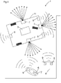
- figure 1 shows a security system 1 for locating and identifying a person 2, with a control and evaluation unit 3, with at least one radio location system 4, with at least one identification sensor 7 for identifying the person 2, with a marking 9 being arranged on the person, the radio location system 4 has radio stations 5, wherein at least one radio transponder 6 is arranged on the person 2, with the position data of the person 2 being able to be determined by means of the radio location system 4, with the position data being able to be transmitted from the radio station 5 of the radio location system 4 to the control and evaluation unit 3, and identification data from the marking 9 on the person 2 can be determined by means of the identification sensor 7, wherein the identification data can be transmitted from the identification sensor 7 to the control and evaluation unit 3, wherein the control and evaluation unit 3 is designed to use the position data of the radio location system 4 and the I to compare identification data of the identification sensor 7 and to form checked personal data if there is a valid match.
- figure 2 shows analogous to figure 1 a security system 1 for locating and identifying an object 8, with a control and evaluation unit 3, with at least one radio location system 4, with at least one identification sensor 7 for identifying the object 8.
- the control and evaluation unit 3 has inputs, a processing unit and outputs.
- the identification sensor 7 and the radio stations 5 are connected to the inputs.
- the control and evaluation unit 3 can be a modular control and evaluation unit that can be programmed using software.
- the outputs of the control and evaluation unit 3 can in particular be redundant safety outputs. This is for example semiconductor-controlled switching outputs, for example to safely switch off a machine drive.
- the first of the two sensor technologies is the radio location system 4 or a radio-based localization system with which the positions of radio transponders 6 can be determined with an accuracy of a few centimeters.
- the radio location system 4 optionally supplies classification information or identification information in addition to the position of the object 8 or the person 2 .
- the second system is the identification sensor 7.
- a marking 9 or optionally a transponder on the person 2 or the object 8 is required.
- Identification information is thus directly accessible for the identification sensor 7 .
- This identification sensor 7 thus supplies information about the person 2 or the object 8, for example whether the person 2 is an authorized person 2 who has certain access authorizations or, in the case of an object 8, whether it is an authorized or an inadmissible object 8 is or, for example, what type the object 8 is and, for example, what dimensions the object 8 has.
- a validation of an object or person identification and an object or person position could be in accordance figure 3 proceed as follows:
- the radio location system 4 determines the position of an object 8 or a person 2, the object 8 or the person being located via the radio transponder 6. This information is transmitted to the control and evaluation unit 3 .
- control and evaluation unit 3 transmits a search field, in which the radio location system 4 has identified the person 2 or the object 8, to the identification sensor 7.
- the identification sensor 7 checks whether a person 2 or an object 8 of suitable size and possibly other validation parameters such as shape etc. are detected in its detection area or its search field.
- the identification sensor 7 transmits the recorded data to the control and evaluation unit 3.
- the control and evaluation unit 3 compares the detected features or the identification data of the person 2 or the object 8 of the identification sensor 7 with the detected features or the contour of the person 2 or the object 8 of the radio location system 4.
- the detected position of the person 2 or the object 8 of the radio location system 4 and the detected identification data of the person 2 or the object 8 of the identification sensor 7 are compared with one another.
- both the person or object identification and the person or object position can be mutually validated by the two diverse information channels and thus checked for a safety-related application.
- figure 3 contains the marking 9, the identification information for the person 2 or the object 8, whereby the person 2 or the object 8 is clearly identifiable.
- the identification sensor 7 and the radio stations 5 are arranged in a stationary manner.
- the identification sensor 7 and the mobile radio stations 5 are arranged on a movable machine 11 .
- the moveable machine 11 or mobile machine can be, for example, a driverless vehicle or figure 5 be a robot with movable robotic arms.
- the movable machine 11 thus has a drive and can be moved in different directions.
- the radio location system 4 is optionally an ultra-wideband radio location system, the frequency used being in the range from 3.1 GHz to 10.6 GHz, with the transmission energy per radio station being a maximum of 0.5 mW.
- At least a single radio transponder 6 must be arranged on the person 2 or the object 8, which is detected by at least three stationarily arranged radio stations 5, the distance between the radio stations 5 being known.
- radio stations 5 are preferably arranged, which monitor at least part of the range of movement of the person 2 or the object 8 .
- At least two or more radio transponders 6 can also be arranged on person 2 or object 8 .
- the position of the person 2 or the object 8 can be identified more precisely and the orientation of the person 2 or the object 8 can also be recorded when the person 2 or the object 8 is stationary, if the arrangement of the radio transponder 6 on the person 2 or the object 8 is known.
- the identification sensor 7 is optionally an RFID sensor or an RFID reader or a barcode sensor.
- an RFID transponder is arranged as a marking 9 on the person 2 or the object 8 .
- the identification sensor 7 is designed as a barcode sensor, a barcode, a barcode, a QR code, a data matrix code or the like is attached to the object 8 or the person 2 as a marking 9 .
- the barcode sensor is designed to read the identification data of the object 8 or the person 2 from the barcode and to transmit it to the control and evaluation unit 3 .
- At least one encoder is optionally arranged on the person 2 or the object 8 in order to verify the position of the person 2 or the object 8 .
- the encoder is connected to the control and evaluation unit 3 and the control and evaluation unit 3 is designed to evaluate the movement information from the encoder.
- location-resolving sensors can be arranged in addition to the radio location system 4 in order to determine the position of the person or the object.
- the position-resolving sensor checks whether a person 2 or an object 8 of suitable size and possibly other validation parameters such as shape, speed, etc. are detected in its detection area or its search field.
- the spatially resolving sensor transmits the recorded data to the control and evaluation unit 3.
- the control and evaluation unit 3 compares the detected features or the contour of the person 2 or the object 8 of the location-resolving sensor with the detected features or the contour of the person 2 or the object 8 of the radio location system 4.
- the location-resolving sensor is optionally a laser scanner .
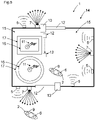
- FIG. 5 if at least one spatially limited access area 12 with at least one access station 13 is arranged for a system 14, with the system 14 having at least one security area 15 and at least one danger area 16 within the security area 15, with the security area 15 being accessible only via the access area 12, so that the access area 12 can be passed by the person 2 or by the object 8 before reaching the security area 15 and after leaving the security area 15, the access area 12 only being passable if personal data or object data have been checked.
- a person 2 it is possible for a person 2 to be in the danger area 16 because the dangerous or dangerous movement in this area has been transferred to a safe state, for example it has been stopped or has a safe low speed of movement. For example, however, production can continue in an adjacent danger area 16 with productive operation of a machine, since there is no person there.
- the access area 12 is a spatially limited access area 12 with an access station 13, for example a gate or a door.
- the security area 15 of the system 14 is only accessible through this access area 12 .
- Several access areas 12 can also be arranged. This can make sense especially in the case of very large systems with, for example, several security areas 15 .
- the access station 13 can, for example, have electronic means, such as an electronic door switch, which makes it possible to check whether the access area 12 has been opened.
- electronic means such as an electronic door switch
- the plant 14 can be, for example, an industrial plant for the manufacture of products. For example, this is part of a production plant for automobiles.
- the system 14 can also be part of a machine or a system 14 with several machines.
- the system 14 has a security area 15 which may not be entered by people 2 when the system 14 is active, since the person 2 can be endangered by parts of the system 14 .
- the system 14 is one or more robots whose dangerous area of action lies within the safety area 15 .
- the access station 13 of the access area 12 can optionally be locked and can only be passed by authorized persons 2 with verified personal data or authorized objects 8 with verified object data.
- a warning area 17 is optionally formed adjoining the danger area 16 , with a dangerous movement of a machine in at least one danger area 16 being transferred to a safe state if the person 2 or the object 8 is in the warning area 17 .
- the warning area 17 means that people 2 are allowed to move outside the warning area 17 and outside the danger area 16 in the safety area 15 . However, as soon as a person 2 is in the warning area 17, the movement in the danger area 16 is transferred to the safe state.
- the warning area 17 forms a defined, fixed zone in order to initiate a safe state in the danger area 16 . Depending on the run-on time of the machine, the warning area 17 can be made larger or smaller. In this case, the danger area 16 is only accessible via the warning area 17 .
- At least that part of the system in whose area the person 2 or the object 8 is detected is in a safe state.
- the remaining parts of the system 14 can continue to be operated productively.
Landscapes
- Engineering & Computer Science (AREA)
- General Engineering & Computer Science (AREA)
- Mechanical Engineering (AREA)
- Physics & Mathematics (AREA)
- Radar, Positioning & Navigation (AREA)
- Remote Sensing (AREA)
- General Physics & Mathematics (AREA)
- Electromagnetism (AREA)
- Health & Medical Sciences (AREA)
- General Health & Medical Sciences (AREA)
- Toxicology (AREA)
- Artificial Intelligence (AREA)
- Computer Vision & Pattern Recognition (AREA)
- Theoretical Computer Science (AREA)
- Computer Networks & Wireless Communication (AREA)
- Signal Processing (AREA)
- Radar Systems Or Details Thereof (AREA)
Claims (13)
- Système de sécurité (1) pour localiser et identifier une personne (2) ou un objet (8), comprenant une unité de commande et d'évaluation (3), au moins un système de radiolocalisation (4), au moins un capteur d'identification (7) pour identifier la personne (2) ou l'objet (8), dans lequel un marquage (9) est disposé sur la personne (2) ou sur l'objet (8),le système de radiolocalisation (4) présente des stations radio (5) mises en place,au moins un transpondeur radio (6) est disposé sur la personne (2) ou sur l'objet (8),des données de position de la personne (2) ou de l'objet (8) peuvent être déterminées au moyen du système de radiolocalisation (4),les données de position peuvent être transmises de la station radio (5) du système de radiolocalisation (4) à l'unité de commande et d'évaluation (3), etau moyen du capteur d'identification (7), des données d'identification peuvent être déterminées à partir du marquage sur la personne (2) ou sur l'objet (8),les données d'identification peuvent être transmises du capteur d'identification (7) à l'unité de commande et d'évaluation (3),l'unité de commande et d'évaluation (3) est réalisée pour comparer les données de position du système de radiolocalisation (4) et les données d'identification du capteur d'identification (7) et pour, en cas de concordance valable, former des données vérifiées de la personne ou des données vérifiées de l'objet.
- Système de sécurité (1) selon la revendication 1, caractérisé en ce que le capteur d'identification (7) et les stations radio (5) sont disposés de manière stationnaire ou sont disposés de manière mobile sur une machine mobile (11).
- Système de sécurité (1) selon l'une au moins des revendications précédentes, caractérisé en ce que le système de radiolocalisation (4) est un système de radiolocalisation à ultra large bande, la fréquence utilisée étant dans la plage de 3,1 GHz à 10,6 GHz, l'énergie d'émission par station radio (5) étant au maximum de 0,5 mW.
- Système de sécurité (1) selon l'une au moins des revendications précédentes, caractérisé en ce que le capteur d'identification (7) est un capteur RFID ou un capteur à code-barres.
- Système de sécurité (1) selon l'une au moins des revendications précédentes, caractérisé en ce qu'en supplément, il est prévu au moins un encodeur pour vérifier la position de l'objet (8).
- Système de sécurité (1) selon l'une au moins des revendications précédentes, caractérisé en ce qu'en supplément au système de radiolocalisation (4), il est prévu au moins un capteur à résolution spatiale pour définir la position de la personne (2) ou de l'objet (8).
- Système de sécurité (1) selon la revendication 6, caractérisé en ce que le capteur à résolution spatiale est un scanner laser.
- Système de sécurité (1) selon l'une au moins des revendications précédentes, caractérisé en ce qu'il est prévu au moins une zone d'accès (12) limitée dans l'espace, comportant au moins une station d'accès (13) pour une installation (14),l'installation (14) présentant au moins une zone de sécurité (15) et au moins une zone de danger (16) à l'intérieur de la zone de sécurité (15),la zone de sécurité (15) n'étant accessible que par la zone d'accès (12), de sorte que la zone d'accès (12) peut être franchie par la personne (2) ou par l'objet (8) avant d'atteindre la zone de sécurité (15) et après avoir quitté la zone de sécurité (15),la zone d'accès (12) ne pouvant être franchie que si les données de la personne ou les données de l'objet sont vérifiées.
- Système de sécurité (1) selon l'une au moins des revendications précédentes, caractérisé en ce que la station d'accès (13) de la zone d'accès (12) peut être verrouillée et ne peut être franchie que par des personnes autorisées (2) ou des objets autorisés (8).
- Système de sécurité (1) selon l'une au moins des revendications précédentes, caractérisé en ce qu'un mouvement dangereux d'une machine mobile (11) dans au moins une zone de danger (16) est converti en un état sûr lorsque la personne (2) ou l'objet (8) s'approche de la zone de danger (16) ou lorsque la personne (2) ou l'objet (8) se trouve dans la zone de danger (16).
- Système de sécurité (1) selon l'une au moins des revendications précédentes, caractérisé en ce qu'une zone d'avertissement (17) est formée de manière adjacente à la zone de danger (16), un mouvement dangereux d'une machine mobile (11) dans au moins une zone de danger (16) étant converti en un état sûr lorsque la personne (2) ou l'objet (8) se trouve dans la zone d'avertissement (17).
- Système de sécurité (1) selon l'une au moins des revendications précédentes, caractérisé en ce que au moins la partie d'une installation (14), au niveau de laquelle la personne (2) ou l'objet (8) est détecté(e), est dans un état sûr.
- Procédé utilisant un système de sécurité (1) pour localiser et identifier une personne (2) ou un objet (8), comprenant une unité de commande et d'évaluation (3), au moins un système de radiolocalisation (4), au moins un capteur d'identification (7) pour identifier la personne (2) ou l'objet (8),dans lequel un marquage (9) est disposé sur la personne (2) ou sur l'objet (8),le système de radiolocalisation (4) présente des stations radio (5) mises en place,au moins un transpondeur radio (6) est disposé sur la personne (2) ou sur l'objet (8),des données de position de la personne (2) ou de l'objet (8) sont déterminées au moyen du système de radiolocalisation (4),les données de position sont transmises de la station radio (5) du système de radiolocalisation (4) à l'unité de commande et d'évaluation (3), etau moyen du capteur d'identification (7), des données d'identification sont déterminées à partir du marquage sur la personne (2) ou sur l'objet (8), les données d'identification sont transmises du capteur d'identification (7) à l'unité de commande et d'évaluation (3),l'unité de commande et d'évaluation (3) compare les données de position du système de radiolocalisation (4) et les données d'identification du capteur d'identification (7) et, en cas de concordance valable, forme des données vérifiées de la personne ou des données vérifiées de l'objet.
Applications Claiming Priority (1)
| Application Number | Priority Date | Filing Date | Title |
|---|---|---|---|
| DE102020112699.9A DE102020112699B4 (de) | 2020-05-11 | 2020-05-11 | Sicherheitssystem |
Publications (2)
| Publication Number | Publication Date |
|---|---|
| EP3910231A1 EP3910231A1 (fr) | 2021-11-17 |
| EP3910231B1 true EP3910231B1 (fr) | 2022-11-02 |
Family
ID=75497857
Family Applications (1)
| Application Number | Title | Priority Date | Filing Date |
|---|---|---|---|
| EP21168060.8A Active EP3910231B1 (fr) | 2020-05-11 | 2021-04-13 | Système de sécurité |
Country Status (4)
| Country | Link |
|---|---|
| US (1) | US11674641B2 (fr) |
| EP (1) | EP3910231B1 (fr) |
| CN (1) | CN113645569A (fr) |
| DE (1) | DE102020112699B4 (fr) |
Families Citing this family (2)
| Publication number | Priority date | Publication date | Assignee | Title |
|---|---|---|---|---|
| DE102022118737B3 (de) * | 2022-07-26 | 2023-09-28 | Pilz Gmbh & Co. Kg | Funkortungssystem mit Testeinrichtung |
| DE102023002751A1 (de) | 2022-08-03 | 2024-02-08 | Sew-Eurodrive Gmbh & Co Kg | Verfahren zum Betreiben einer technischen Anlage |
Family Cites Families (15)
| Publication number | Priority date | Publication date | Assignee | Title |
|---|---|---|---|---|
| US7123126B2 (en) * | 2002-03-26 | 2006-10-17 | Kabushiki Kaisha Toshiba | Method of and computer program product for monitoring person's movements |
| DE10245720A1 (de) | 2002-09-24 | 2004-04-01 | Pilz Gmbh & Co. | Verfahren un Vorrichtung zum Absichern eines Gefahrenbereichs |
| DE10347894B4 (de) * | 2003-10-15 | 2005-11-24 | Dräger Safety AG & Co. KGaA | Vorrichtung und Verfahren zum kontrollierten Betreten oder Verlassen eines Bereiches |
| JP4443322B2 (ja) * | 2004-06-23 | 2010-03-31 | アルプス電気株式会社 | 押圧センサ |
| US7504952B2 (en) * | 2005-12-28 | 2009-03-17 | Sandlinks Ltd. | Wide band RFID system with tag on flexible label |
| DE102006042547A1 (de) | 2006-09-11 | 2008-03-27 | Bartec Gmbh | System zum Überwachen eines Gefahrenbereiches, insbesondere eines Fahrzeugs |
| EP2364243B1 (fr) * | 2008-12-03 | 2012-08-01 | ABB Research Ltd. | Système de sécurité de robot et procédé associé |
| DE102009036641A1 (de) * | 2009-08-07 | 2011-02-10 | Sick Ag | Sicherung eines nur über eine sichere Zugangsschleuse zugänglichen Raumbereichs |
| EP2386876B1 (fr) * | 2010-05-04 | 2013-07-10 | Sick AG | Capteur de sécurité optoélectronique mesurant l'éloignement et procédé de surveillance d'une zone de surveillance |
| DE102012102236A1 (de) * | 2012-03-16 | 2013-09-19 | Pilz Gmbh & Co. Kg | Verfahren und Vorrichtung zum Absichern eines gefährlichen Arbeitsbereichs einer automatisiert arbeitenden Maschine |
| DE102014101513A1 (de) | 2014-02-06 | 2015-08-06 | Marco Systemanalyse Und Entwicklung Gmbh | Untertagebauortungssystem |
| EP3193071B1 (fr) * | 2016-01-18 | 2018-07-11 | Sick Ag | Systeme de securite |
| DE102016203077A1 (de) | 2016-02-26 | 2017-08-31 | Robert Bosch Gmbh | System und Verfahren zum Lokalisieren |
| DE102017102116A1 (de) * | 2017-02-03 | 2018-08-09 | Jungheinrich Aktiengesellschaft | Verfahren und System zur Positionsbestimmung von mindestens einem Flurförderzeug |
| DE102017123295A1 (de) * | 2017-10-06 | 2019-04-11 | Pilz Gmbh & Co. Kg | Sicherheitssystem zur Absicherung eines kooperativen Betriebs von Menschen, Robotern und Maschinen |
-
2020
- 2020-05-11 DE DE102020112699.9A patent/DE102020112699B4/de active Active
-
2021
- 2021-04-13 EP EP21168060.8A patent/EP3910231B1/fr active Active
- 2021-05-07 US US17/314,608 patent/US11674641B2/en active Active
- 2021-05-11 CN CN202110511502.0A patent/CN113645569A/zh active Pending
Also Published As
| Publication number | Publication date |
|---|---|
| US11674641B2 (en) | 2023-06-13 |
| US20210348718A1 (en) | 2021-11-11 |
| EP3910231A1 (fr) | 2021-11-17 |
| DE102020112699B4 (de) | 2024-10-10 |
| CN113645569A (zh) | 2021-11-12 |
| DE102020112699A1 (de) | 2021-11-11 |
Similar Documents
| Publication | Publication Date | Title |
|---|---|---|
| EP3290770B1 (fr) | Dispositif de surveillance | |
| EP3373093B1 (fr) | Système de transport sans conducteur | |
| DE102020101482B3 (de) | Sicherheitssystem und Verfahren | |
| EP3910231B1 (fr) | Système de sécurité | |
| EP3193071B1 (fr) | Systeme de securite | |
| EP3401702B1 (fr) | Système de capteur | |
| EP3859382B1 (fr) | Système de sécurité et procédé de localisation d'une personne ou d'un objet dans une zone de surveillance à l'aide d'un système de sécurité | |
| DE102020133784B3 (de) | Sicherheitssystem und ein Verfahren mit einem Sicherheitssystem | |
| DE202020107300U1 (de) | Sicherheitssystem | |
| EP3859367B1 (fr) | Système de sécurité et procédé de localisation | |
| EP4024075B1 (fr) | Système de sécurité et procédé comprenant un système de sécurité | |
| DE102020133787A1 (de) | Sicherheitssystem und Verfahren mit einem Sicherheitssystem | |
| DE202020107298U1 (de) | Sicherheitssystem | |
| DE202016105595U1 (de) | Sicherheitssystem mit einem Sicherheitsschalter | |
| EP3015755B1 (fr) | Élément RFID, système d'émetteur/récepteur RFID ainsi que commutateur de sécurité | |
| EP3306173B1 (fr) | Système de sécurité doté d'un dispositif de sécurité par coupure | |
| EP3825731B1 (fr) | Capteur optoélectronique de sécurité et procédé de détermination sécurisée de position propre | |
| DE202020100454U1 (de) | Sicherheitssystem zur Lokalisierung einer Person oder eines Objektes in einem Überwachungsbereich | |
| EP3770708B1 (fr) | Dispositif de surveillance | |
| EP3193312B1 (fr) | Dispositif clé avec un lecteur de données sans fil intégré | |
| EP2703920B1 (fr) | Procédé d'apprentissage de la commande d'une machine | |
| EP3220039B1 (fr) | Systeme comprenant un appareil mobile a code | |
| DE102022133248A1 (de) | System mit einem Sensor und Verfahren mit einem Sensor zur Überwachung mehrerer Schutzbereiche | |
| DE202022106978U1 (de) | System mit einem Sensor | |
| DE202020107303U1 (de) | Sicherheitssystem |
Legal Events
| Date | Code | Title | Description |
|---|---|---|---|
| PUAI | Public reference made under article 153(3) epc to a published international application that has entered the european phase |
Free format text: ORIGINAL CODE: 0009012 |
|
| STAA | Information on the status of an ep patent application or granted ep patent |
Free format text: STATUS: THE APPLICATION HAS BEEN PUBLISHED |
|
| AK | Designated contracting states |
Kind code of ref document: A1 Designated state(s): AL AT BE BG CH CY CZ DE DK EE ES FI FR GB GR HR HU IE IS IT LI LT LU LV MC MK MT NL NO PL PT RO RS SE SI SK SM TR |
|
| B565 | Issuance of search results under rule 164(2) epc |
Effective date: 20211006 |
|
| STAA | Information on the status of an ep patent application or granted ep patent |
Free format text: STATUS: REQUEST FOR EXAMINATION WAS MADE |
|
| 17P | Request for examination filed |
Effective date: 20220310 |
|
| RBV | Designated contracting states (corrected) |
Designated state(s): AL AT BE BG CH CY CZ DE DK EE ES FI FR GB GR HR HU IE IS IT LI LT LU LV MC MK MT NL NO PL PT RO RS SE SI SK SM TR |
|
| GRAP | Despatch of communication of intention to grant a patent |
Free format text: ORIGINAL CODE: EPIDOSNIGR1 |
|
| STAA | Information on the status of an ep patent application or granted ep patent |
Free format text: STATUS: GRANT OF PATENT IS INTENDED |
|
| INTG | Intention to grant announced |
Effective date: 20220722 |
|
| GRAS | Grant fee paid |
Free format text: ORIGINAL CODE: EPIDOSNIGR3 |
|
| GRAA | (expected) grant |
Free format text: ORIGINAL CODE: 0009210 |
|
| STAA | Information on the status of an ep patent application or granted ep patent |
Free format text: STATUS: THE PATENT HAS BEEN GRANTED |
|
| AK | Designated contracting states |
Kind code of ref document: B1 Designated state(s): AL AT BE BG CH CY CZ DE DK EE ES FI FR GB GR HR HU IE IS IT LI LT LU LV MC MK MT NL NO PL PT RO RS SE SI SK SM TR |
|
| REG | Reference to a national code |
Ref country code: GB Ref legal event code: FG4D Free format text: NOT ENGLISH |
|
| REG | Reference to a national code |
Ref country code: CH Ref legal event code: EP Ref country code: AT Ref legal event code: REF Ref document number: 1528976 Country of ref document: AT Kind code of ref document: T Effective date: 20221115 |
|
| REG | Reference to a national code |
Ref country code: DE Ref legal event code: R096 Ref document number: 502021000229 Country of ref document: DE |
|
| REG | Reference to a national code |
Ref country code: IE Ref legal event code: FG4D Free format text: LANGUAGE OF EP DOCUMENT: GERMAN |
|
| REG | Reference to a national code |
Ref country code: LT Ref legal event code: MG9D |
|
| REG | Reference to a national code |
Ref country code: NL Ref legal event code: MP Effective date: 20221102 |
|
| PG25 | Lapsed in a contracting state [announced via postgrant information from national office to epo] |
Ref country code: SE Free format text: LAPSE BECAUSE OF FAILURE TO SUBMIT A TRANSLATION OF THE DESCRIPTION OR TO PAY THE FEE WITHIN THE PRESCRIBED TIME-LIMIT Effective date: 20221102 Ref country code: PT Free format text: LAPSE BECAUSE OF FAILURE TO SUBMIT A TRANSLATION OF THE DESCRIPTION OR TO PAY THE FEE WITHIN THE PRESCRIBED TIME-LIMIT Effective date: 20230302 Ref country code: NO Free format text: LAPSE BECAUSE OF FAILURE TO SUBMIT A TRANSLATION OF THE DESCRIPTION OR TO PAY THE FEE WITHIN THE PRESCRIBED TIME-LIMIT Effective date: 20230202 Ref country code: LT Free format text: LAPSE BECAUSE OF FAILURE TO SUBMIT A TRANSLATION OF THE DESCRIPTION OR TO PAY THE FEE WITHIN THE PRESCRIBED TIME-LIMIT Effective date: 20221102 Ref country code: FI Free format text: LAPSE BECAUSE OF FAILURE TO SUBMIT A TRANSLATION OF THE DESCRIPTION OR TO PAY THE FEE WITHIN THE PRESCRIBED TIME-LIMIT Effective date: 20221102 Ref country code: ES Free format text: LAPSE BECAUSE OF FAILURE TO SUBMIT A TRANSLATION OF THE DESCRIPTION OR TO PAY THE FEE WITHIN THE PRESCRIBED TIME-LIMIT Effective date: 20221102 |
|
| PG25 | Lapsed in a contracting state [announced via postgrant information from national office to epo] |
Ref country code: RS Free format text: LAPSE BECAUSE OF FAILURE TO SUBMIT A TRANSLATION OF THE DESCRIPTION OR TO PAY THE FEE WITHIN THE PRESCRIBED TIME-LIMIT Effective date: 20221102 Ref country code: PL Free format text: LAPSE BECAUSE OF FAILURE TO SUBMIT A TRANSLATION OF THE DESCRIPTION OR TO PAY THE FEE WITHIN THE PRESCRIBED TIME-LIMIT Effective date: 20221102 Ref country code: LV Free format text: LAPSE BECAUSE OF FAILURE TO SUBMIT A TRANSLATION OF THE DESCRIPTION OR TO PAY THE FEE WITHIN THE PRESCRIBED TIME-LIMIT Effective date: 20221102 Ref country code: IS Free format text: LAPSE BECAUSE OF FAILURE TO SUBMIT A TRANSLATION OF THE DESCRIPTION OR TO PAY THE FEE WITHIN THE PRESCRIBED TIME-LIMIT Effective date: 20230302 Ref country code: HR Free format text: LAPSE BECAUSE OF FAILURE TO SUBMIT A TRANSLATION OF THE DESCRIPTION OR TO PAY THE FEE WITHIN THE PRESCRIBED TIME-LIMIT Effective date: 20221102 Ref country code: GR Free format text: LAPSE BECAUSE OF FAILURE TO SUBMIT A TRANSLATION OF THE DESCRIPTION OR TO PAY THE FEE WITHIN THE PRESCRIBED TIME-LIMIT Effective date: 20230203 |
|
| PG25 | Lapsed in a contracting state [announced via postgrant information from national office to epo] |
Ref country code: NL Free format text: LAPSE BECAUSE OF FAILURE TO SUBMIT A TRANSLATION OF THE DESCRIPTION OR TO PAY THE FEE WITHIN THE PRESCRIBED TIME-LIMIT Effective date: 20221102 |
|
| PG25 | Lapsed in a contracting state [announced via postgrant information from national office to epo] |
Ref country code: SM Free format text: LAPSE BECAUSE OF FAILURE TO SUBMIT A TRANSLATION OF THE DESCRIPTION OR TO PAY THE FEE WITHIN THE PRESCRIBED TIME-LIMIT Effective date: 20221102 Ref country code: RO Free format text: LAPSE BECAUSE OF FAILURE TO SUBMIT A TRANSLATION OF THE DESCRIPTION OR TO PAY THE FEE WITHIN THE PRESCRIBED TIME-LIMIT Effective date: 20221102 Ref country code: EE Free format text: LAPSE BECAUSE OF FAILURE TO SUBMIT A TRANSLATION OF THE DESCRIPTION OR TO PAY THE FEE WITHIN THE PRESCRIBED TIME-LIMIT Effective date: 20221102 Ref country code: DK Free format text: LAPSE BECAUSE OF FAILURE TO SUBMIT A TRANSLATION OF THE DESCRIPTION OR TO PAY THE FEE WITHIN THE PRESCRIBED TIME-LIMIT Effective date: 20221102 Ref country code: CZ Free format text: LAPSE BECAUSE OF FAILURE TO SUBMIT A TRANSLATION OF THE DESCRIPTION OR TO PAY THE FEE WITHIN THE PRESCRIBED TIME-LIMIT Effective date: 20221102 |
|
| REG | Reference to a national code |
Ref country code: DE Ref legal event code: R097 Ref document number: 502021000229 Country of ref document: DE |
|
| PG25 | Lapsed in a contracting state [announced via postgrant information from national office to epo] |
Ref country code: SK Free format text: LAPSE BECAUSE OF FAILURE TO SUBMIT A TRANSLATION OF THE DESCRIPTION OR TO PAY THE FEE WITHIN THE PRESCRIBED TIME-LIMIT Effective date: 20221102 Ref country code: AL Free format text: LAPSE BECAUSE OF FAILURE TO SUBMIT A TRANSLATION OF THE DESCRIPTION OR TO PAY THE FEE WITHIN THE PRESCRIBED TIME-LIMIT Effective date: 20221102 |
|
| PLBE | No opposition filed within time limit |
Free format text: ORIGINAL CODE: 0009261 |
|
| STAA | Information on the status of an ep patent application or granted ep patent |
Free format text: STATUS: NO OPPOSITION FILED WITHIN TIME LIMIT |
|
| 26N | No opposition filed |
Effective date: 20230803 |
|
| PG25 | Lapsed in a contracting state [announced via postgrant information from national office to epo] |
Ref country code: SI Free format text: LAPSE BECAUSE OF FAILURE TO SUBMIT A TRANSLATION OF THE DESCRIPTION OR TO PAY THE FEE WITHIN THE PRESCRIBED TIME-LIMIT Effective date: 20221102 |
|
| PG25 | Lapsed in a contracting state [announced via postgrant information from national office to epo] |
Ref country code: LU Free format text: LAPSE BECAUSE OF NON-PAYMENT OF DUE FEES Effective date: 20230413 |
|
| REG | Reference to a national code |
Ref country code: BE Ref legal event code: MM Effective date: 20230430 |
|
| PG25 | Lapsed in a contracting state [announced via postgrant information from national office to epo] |
Ref country code: MC Free format text: LAPSE BECAUSE OF FAILURE TO SUBMIT A TRANSLATION OF THE DESCRIPTION OR TO PAY THE FEE WITHIN THE PRESCRIBED TIME-LIMIT Effective date: 20221102 |
|
| PG25 | Lapsed in a contracting state [announced via postgrant information from national office to epo] |
Ref country code: MC Free format text: LAPSE BECAUSE OF FAILURE TO SUBMIT A TRANSLATION OF THE DESCRIPTION OR TO PAY THE FEE WITHIN THE PRESCRIBED TIME-LIMIT Effective date: 20221102 Ref country code: FR Free format text: LAPSE BECAUSE OF NON-PAYMENT OF DUE FEES Effective date: 20230430 |
|
| REG | Reference to a national code |
Ref country code: IE Ref legal event code: MM4A |
|
| PG25 | Lapsed in a contracting state [announced via postgrant information from national office to epo] |
Ref country code: BE Free format text: LAPSE BECAUSE OF NON-PAYMENT OF DUE FEES Effective date: 20230430 |
|
| PG25 | Lapsed in a contracting state [announced via postgrant information from national office to epo] |
Ref country code: IE Free format text: LAPSE BECAUSE OF NON-PAYMENT OF DUE FEES Effective date: 20230413 |
|
| PG25 | Lapsed in a contracting state [announced via postgrant information from national office to epo] |
Ref country code: IE Free format text: LAPSE BECAUSE OF NON-PAYMENT OF DUE FEES Effective date: 20230413 |
|
| PG25 | Lapsed in a contracting state [announced via postgrant information from national office to epo] |
Ref country code: IT Free format text: LAPSE BECAUSE OF FAILURE TO SUBMIT A TRANSLATION OF THE DESCRIPTION OR TO PAY THE FEE WITHIN THE PRESCRIBED TIME-LIMIT Effective date: 20221102 |
|
| PGFP | Annual fee paid to national office [announced via postgrant information from national office to epo] |
Ref country code: DE Payment date: 20240418 Year of fee payment: 4 |