EP3770708B1 - Dispositif de surveillance - Google Patents
Dispositif de surveillance Download PDFInfo
- Publication number
- EP3770708B1 EP3770708B1 EP19188184.6A EP19188184A EP3770708B1 EP 3770708 B1 EP3770708 B1 EP 3770708B1 EP 19188184 A EP19188184 A EP 19188184A EP 3770708 B1 EP3770708 B1 EP 3770708B1
- Authority
- EP
- European Patent Office
- Prior art keywords
- sensors
- sensor
- monitoring
- monitoring device
- communication
- Prior art date
- Legal status (The legal status is an assumption and is not a legal conclusion. Google has not performed a legal analysis and makes no representation as to the accuracy of the status listed.)
- Active
Links
- 238000012806 monitoring device Methods 0.000 title claims description 36
- 230000001681 protective effect Effects 0.000 claims description 58
- 238000004891 communication Methods 0.000 claims description 43
- 238000012544 monitoring process Methods 0.000 claims description 35
- 230000004888 barrier function Effects 0.000 claims description 18
- 230000003287 optical effect Effects 0.000 claims description 9
- 238000000034 method Methods 0.000 description 10
- 238000011156 evaluation Methods 0.000 description 9
- 238000004519 manufacturing process Methods 0.000 description 7
- 230000005540 biological transmission Effects 0.000 description 6
- 238000001514 detection method Methods 0.000 description 4
- 238000005516 engineering process Methods 0.000 description 3
- 230000002457 bidirectional effect Effects 0.000 description 2
- 230000001419 dependent effect Effects 0.000 description 2
- 230000007613 environmental effect Effects 0.000 description 2
- 231100001261 hazardous Toxicity 0.000 description 2
- 238000004364 calculation method Methods 0.000 description 1
- 238000013461 design Methods 0.000 description 1
- 238000011161 development Methods 0.000 description 1
- 230000018109 developmental process Effects 0.000 description 1
- 238000005259 measurement Methods 0.000 description 1
Images


Classifications
-
- G—PHYSICS
- G05—CONTROLLING; REGULATING
- G05B—CONTROL OR REGULATING SYSTEMS IN GENERAL; FUNCTIONAL ELEMENTS OF SUCH SYSTEMS; MONITORING OR TESTING ARRANGEMENTS FOR SUCH SYSTEMS OR ELEMENTS
- G05B19/00—Programme-control systems
- G05B19/02—Programme-control systems electric
- G05B19/418—Total factory control, i.e. centrally controlling a plurality of machines, e.g. direct or distributed numerical control [DNC], flexible manufacturing systems [FMS], integrated manufacturing systems [IMS], computer integrated manufacturing [CIM]
- G05B19/4189—Total factory control, i.e. centrally controlling a plurality of machines, e.g. direct or distributed numerical control [DNC], flexible manufacturing systems [FMS], integrated manufacturing systems [IMS], computer integrated manufacturing [CIM] characterised by the transport system
- G05B19/41895—Total factory control, i.e. centrally controlling a plurality of machines, e.g. direct or distributed numerical control [DNC], flexible manufacturing systems [FMS], integrated manufacturing systems [IMS], computer integrated manufacturing [CIM] characterised by the transport system using automatic guided vehicles [AGV]
-
- G—PHYSICS
- G05—CONTROLLING; REGULATING
- G05B—CONTROL OR REGULATING SYSTEMS IN GENERAL; FUNCTIONAL ELEMENTS OF SUCH SYSTEMS; MONITORING OR TESTING ARRANGEMENTS FOR SUCH SYSTEMS OR ELEMENTS
- G05B9/00—Safety arrangements
- G05B9/02—Safety arrangements electric
-
- G—PHYSICS
- G05—CONTROLLING; REGULATING
- G05B—CONTROL OR REGULATING SYSTEMS IN GENERAL; FUNCTIONAL ELEMENTS OF SUCH SYSTEMS; MONITORING OR TESTING ARRANGEMENTS FOR SUCH SYSTEMS OR ELEMENTS
- G05B2219/00—Program-control systems
- G05B2219/30—Nc systems
- G05B2219/31—From computer integrated manufacturing till monitoring
- G05B2219/31005—Detect obstacles on path of vehicle
-
- G—PHYSICS
- G05—CONTROLLING; REGULATING
- G05B—CONTROL OR REGULATING SYSTEMS IN GENERAL; FUNCTIONAL ELEMENTS OF SUCH SYSTEMS; MONITORING OR TESTING ARRANGEMENTS FOR SUCH SYSTEMS OR ELEMENTS
- G05B2219/00—Program-control systems
- G05B2219/30—Nc systems
- G05B2219/32—Operator till task planning
- G05B2219/32388—Autonomous flexible system, cells and agv autonomous
-
- G—PHYSICS
- G05—CONTROLLING; REGULATING
- G05B—CONTROL OR REGULATING SYSTEMS IN GENERAL; FUNCTIONAL ELEMENTS OF SUCH SYSTEMS; MONITORING OR TESTING ARRANGEMENTS FOR SUCH SYSTEMS OR ELEMENTS
- G05B2219/00—Program-control systems
- G05B2219/30—Nc systems
- G05B2219/39—Robotics, robotics to robotics hand
- G05B2219/39091—Avoid collision with moving obstacles
-
- G—PHYSICS
- G05—CONTROLLING; REGULATING
- G05B—CONTROL OR REGULATING SYSTEMS IN GENERAL; FUNCTIONAL ELEMENTS OF SUCH SYSTEMS; MONITORING OR TESTING ARRANGEMENTS FOR SUCH SYSTEMS OR ELEMENTS
- G05B2219/00—Program-control systems
- G05B2219/30—Nc systems
- G05B2219/39—Robotics, robotics to robotics hand
- G05B2219/39173—Dynamic interaction between vehicle and manipulator
-
- Y—GENERAL TAGGING OF NEW TECHNOLOGICAL DEVELOPMENTS; GENERAL TAGGING OF CROSS-SECTIONAL TECHNOLOGIES SPANNING OVER SEVERAL SECTIONS OF THE IPC; TECHNICAL SUBJECTS COVERED BY FORMER USPC CROSS-REFERENCE ART COLLECTIONS [XRACs] AND DIGESTS
- Y02—TECHNOLOGIES OR APPLICATIONS FOR MITIGATION OR ADAPTATION AGAINST CLIMATE CHANGE
- Y02P—CLIMATE CHANGE MITIGATION TECHNOLOGIES IN THE PRODUCTION OR PROCESSING OF GOODS
- Y02P90/00—Enabling technologies with a potential contribution to greenhouse gas [GHG] emissions mitigation
- Y02P90/02—Total factory control, e.g. smart factories, flexible manufacturing systems [FMS] or integrated manufacturing systems [IMS]
-
- Y—GENERAL TAGGING OF NEW TECHNOLOGICAL DEVELOPMENTS; GENERAL TAGGING OF CROSS-SECTIONAL TECHNOLOGIES SPANNING OVER SEVERAL SECTIONS OF THE IPC; TECHNICAL SUBJECTS COVERED BY FORMER USPC CROSS-REFERENCE ART COLLECTIONS [XRACs] AND DIGESTS
- Y02—TECHNOLOGIES OR APPLICATIONS FOR MITIGATION OR ADAPTATION AGAINST CLIMATE CHANGE
- Y02P—CLIMATE CHANGE MITIGATION TECHNOLOGIES IN THE PRODUCTION OR PROCESSING OF GOODS
- Y02P90/00—Enabling technologies with a potential contribution to greenhouse gas [GHG] emissions mitigation
- Y02P90/60—Electric or hybrid propulsion means for production processes
Definitions
- the invention relates to a monitoring device.
- Known monitoring devices are used for monitoring danger areas on vehicles, which can be designed in particular as driverless transport systems or generally as autonomous, ie autonomously driving vehicles.
- a sensor is typically arranged on the front side as part of the monitoring device, by means of which the area in front of the vehicle is monitored as a danger area in order to be able to rule out collisions.
- a sensor that is particularly suitable for this is an optical sensor in the form of a surface distance sensor, ie a scanning distance sensor.
- a surface distance sensor object detection is carried out within a protective field adapted to the danger area. If the surface distance sensor detects an object in the protective field, the surface distance sensor generates a safety signal that is sent to the vehicle's vehicle control system, causing the vehicle to stop and dangerous collisions to be avoided.
- sensors of this type in particular area distance sensors, on a stationary machine for monitoring danger areas.
- the monitoring devices mentioned form completely independent units.
- the DE 10 2016 107 564 A1 relates to a safety device and a safety method for a manufacturing station for bodywork components and for a conveying means that enters and exits the manufacturing station for transporting workpieces into and out of the manufacturing station.
- the manufacturing station and the funding each have their own controller and their own safety circuit, the safety device connecting the safety circuits of the manufacturing station and the funding located in the manufacturing station.
- the safety device influences and thereby changes a protective area of a protective device of an intrinsically safe conveying means at the entrance and exit and within the production station.
- the DE 10 2015 220 495 A1 relates to a method for operating a manipulator system, which can include in particular a driverless transport system and also in particular a driverless transport vehicle.
- a protective field of the manipulator system is monitored by a monitoring device.
- the method includes providing environmental information relating to an environment of the manipulator system and adapting the protective field based on the environmental information.
- the invention is based on the object of providing a monitoring device and a method by means of which flexible and safe danger zone monitoring is made possible.
- the invention relates to a monitoring device with sensors on a stationary device and with sensors on a mobile device. At least some of the sensors are designed for communication between the stationary device and the mobile device. Depending on sensor signals, monitoring functionalities are specified in an event-driven manner. Sensors are associated with communication modules, via which information for specifying monitoring functionalities can be transmitted. Sensors exchange information directly via communication modules. Alternatively or additionally, the stationary device and/or the mobile device has a control unit with an assigned communication module for exchanging information with one another and/or with sensors. Monitoring signals generated in sensors are used for inter-sensor communication, with a sensor unit of a sensor being arranged on the stationary device and the mobile device, between which monitoring signals are transmitted, which are used for inter-sensor communication.
- the basic idea of the invention is therefore not to use sensors for object detection, but also for an event-controlled definition of monitoring functionalities. This can be an automatic adjustment of monitoring functionalities to changing boundary conditions, in particular the states of the two devices, whereby the functionality of the monitoring device is significantly increased.
- both the stationary device and the mobile device can be monitored completely and securely, depending on their operating modes and operating states.
- a required safety level must always be met when carrying out monitoring.
- communication modules are assigned to sensors, via which information for specifying monitoring functionalities can be transmitted.
- a bidirectional data exchange advantageously takes place between two communication modules.
- sensors exchange information directly via communication modules.
- monitoring signals generated in sensors are used for inter-sensor communication.
- a sensor unit of a sensor is arranged on the stationary device and the mobile device, between which monitoring signals are transmitted, which are used for inter-sensor communication.
- the stationary device and/or the mobile device has a control unit with an associated communication module for exchanging information with one another and/or with sensors.
- wired data transmission between the control units and the sensors provided on the respective device is also possible.
- the control units can form superordinate units to the sensors in that sensor signals from a number of sensors are collected in a control unit, evaluated and, if necessary, passed on.
- the control units can form a decentralized, non-hierarchical system with the sensors.
- Event-controlled danger zone monitoring is carried out particularly advantageously with the monitoring device according to the invention.
- the danger area(s) to be secured with the monitoring device are automatically adapted to the respective situation of the facilities by the inter-sensor communication, so that the danger areas are completely secured and with the required safety level.
- sensors are designed for protective field monitoring.
- protective fields can be stored in the respective sensors for a number of situations, so that a selection can be made from these.
- protective fields from external units can also be read into the sensors.
- a general advantage of the invention is that no fixed central unit is provided which permanently specifies the security function of the monitoring device. Rather, it is decided in the decentralized system, depending on the current inter-sensor communication, which monitoring functionality is implemented.
- the distributed system formed in this way can react flexibly to changing configurations.
- control units of the devices, the sensors and the communication devices formed by the communication modules form safety-oriented units, i.e. the control units act as safety controllers and the sensors act as Safety sensors are formed.
- control units and the sensors can have a fail-safe, in particular redundant, two-channel structure.
- the communication device can ensure fail-safe data transmission by protection with checksums or the like.
- the communication device can, for example, be designed in such a way that radio signals are transmitted bidirectionally with it.
- the communication modules can form wired or non-contact communication devices.
- One or more sensors are advantageously optical sensors or radar sensors, which are designed to detect objects within two-dimensional and/or three-dimensional protective fields.
- an optical sensor can be designed as a surface distance sensor or a camera sensor or as a distance sensor.
- the optical sensor can also form a light curtain or a light barrier.
- the protective fields are one-, two- or three-dimensional areas.
- a one-dimensional area can be monitored as a protective field with a simple distance sensor or a light barrier, while area distance sensors can and light curtains two-dimensional areas can be monitored. With camera sensors, three-dimensional areas in particular can be monitored as protective fields.
- the stationary device and the mobile device are typically units from which hazards can emanate.
- the devices are in the form of machines, systems, robot cells, vehicles and/or parts of buildings.
- Autonomous vehicles such as, for example, driverless transport systems or other transport devices can be provided as vehicles.
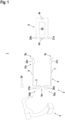
- figure 1 1 shows an exemplary embodiment of the monitoring device 1 according to the invention. This serves to secure danger zones on a robot cell 2 forming a stationary device and a mobile device in the form of an autonomous vehicle designed as a driverless transport system 8 .
- the robot cell 2 comprises a robot 3 and a cell 4 assigned to the robot 3.
- the cell 4 has a rear wall 5 at the rear and a rear wall 5 at the side each side wall 6, 7 completed.
- the front of the cell 4 is open and forms an entrance for the driverless transport system 8. These walls are oriented perpendicularly to a floor on which the driverless transport system 8 drives.
- the driverless transport system 8 has to be driven into the cell 4 in order to deliver material for the robot 3 .
- the monitoring device 1 has a number of sensors for monitoring the danger area.
- the sensors can be formed by radar sensors and the like.
- the sensors are designed as optical sensors, specifically as surface distance sensors 9 and light curtains 10 or light barriers 10a, 10b.
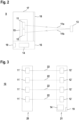
- FIG 2 shows an embodiment of a surface distance sensor 9.
- the surface distance sensor 9 shown there has a transmitter 11 emitting transmitted light beams 11a and a receiver 12 receiving received light beams 11b, which form a distance sensor working according to a pulse transit time method.
- the propagation time of the transmitted light beams 11a from the transmitter 11 to the object 13 and back to the receiver 12 is determined in an evaluation unit 14 and converted into a distance value.
- the transmitter 11 and receiver 12 are arranged in a rotating measuring head 15 . This sits on a stationary base 16 in which the evaluation unit 14 is housed.
- the motor-driven measuring head 15 rotates about a vertical axis of rotation (related to the representation according to FIG. 2).
- These sensor components are arranged in a housing 17 mounted on the base 16 .
- the transmitted light beams 11a and received light beams 11b are guided through a window 18 in the housing 17 .
- a switching output 19 for a signal output is connected to the evaluation unit 14 .
- the transmitted light beams 11a are periodically deflected in a scanning area lying in a horizontal plane.
- the angular range of the scanning range results from the expansion of the window 18 in the circumferential direction of the housing 17.
- the continuous distance measurements and determination of the current angular positions of the transmitted light beams 11a can be used to determine the position of objects 13 in the scanning area.
- the evaluation unit 14 has a redundant structure in the form of two computer units that monitor each other cyclically.
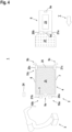
- FIG 3 shows an optical sensor in the form of a light curtain 10, by means of which a flat surveillance area is monitored.
- the light curtain 10 has a transmitter unit 20 and a receiver unit 21, the components of which are each integrated in a housing and which are arranged on opposite edges of the surveillance area.
- the transmitter unit 20 there is a series arrangement of transmitters 11' emitting light beams 22, and in the receiver unit 21 there is a corresponding number of receivers 12'.
- the beam axes are activated cyclically one after the other by a transmitter control (not shown) and an optical synchronization.
- Object detection is based on the light barrier principle.
- a threshold value calculation of the received signals of the receivers 12′ takes place in the evaluation unit 14 in order to generate a binary switching signal.
- a switching signal with the switching state "free monitoring area" is generated in the evaluation unit 14 if the light beams 22 of all beam axes impinge unhindered on the respective receiver 12 ⁇ . If at least one beam axis is interrupted by an object intrusion, a switching signal with the switching state “object present” is generated in the evaluation unit 14 .
- the evaluation unit 14 has a redundant structure. The switching signal is output via a switching output 19.
- a first surface distance sensor 9a is provided on the rear wall 5 of the cell 4, with which the interior of the cell 4 can be monitored.
- a transmitter unit 20a is located on the rear wall 5 of the cell 4, which forms a first light barrier 10a with a receiver unit 21a on the front side of the driverless transport system 8, i.e. the transmitter unit 20a comprises only one transmitter and the receiver unit 21a comprises only one receiver.
- a transmitter unit 20c and a receiver unit 21c of a light curtain 10c are located at the edges of the cell 4 delimiting the entrance.
- a first control unit 23 is integrated in the driverless transport system 8, which is assigned to the sensors of the driverless transport system 8 and which is used to control the vehicle.
- a further control unit 24 is also optionally assigned to the sensors of the robot cell 2 .
- a communication module not shown separately, is provided for contactless bidirectional data transmission.
- the communication modules form a communication device via which information can be exchanged bidirectionally.
- a contactless communication device is provided, with the information being transmitted between the communication modules as radio signals.
- each communication module has a radio transmitter and a radio receiver.
- wired data transmissions can be provided.
- the monitoring device 1 is used in the field of security technology.
- their components, in particular the control units 23, 24, the communication device and the sensors are designed as safety-related units.
- the control units 23, 24 can consist of two computer units that monitor each other cyclically.
- the data transmission via the communication device can be protected by checksums.
- the Figures 4 to 18 show in particular the entry and exit of the driverless transport system 8 into and out of the robot cell 2.
- This process is continuously monitored by the protective field monitoring with the sensors on the robot cell 2 and on the driverless transport system 8.
- the protective fields 25 - 29 required for the protective field monitoring are continuously adapted to the current position of the driverless transport system 8.
- the protective field monitoring is adapted by the inter-sensor communication according to the invention, in which the control units 23, 24 are included.
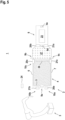
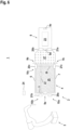
- figure 4 shows the situation when the driverless transport system 8 is at a greater distance from the robot cell 2 and is moving towards it (as illustrated by the arrow I).
- the surface distance sensor 9a on the rear wall 5 of the cell 4 is used to monitor that there is no object 13 or person there.
- a protective field 25 that covers the interior of the cell 4 is monitored with the area distance sensor 9a.
- the protective field 25 runs in a horizontal plane, i.e. parallel to the roadway of the driverless transport system 8.
- the light curtain 10c is used to monitor within a protective field 26 whether an object 13 or a person enters cell 4.
- the protective field 26 of the light curtain 10c runs in a vertical plane.
- the area in front of the driverless transport system 8 is monitored within a protective field 27 with the area distance sensor 9d on the front side of the driverless transport system 8 .
- figure 4 shows the error-free state of the arrangement, ie there is no object 13 in the protective fields 25, 26, 27. This means that, for example, work movements of the robot 3 can be released via the control unit 24. Furthermore, the driverless transport system 8 can move at the target speed.
- the robot 3 is stopped.
- a signal is sent from the control unit 24 or one of the sensors of the robot cell 2 to the control unit 23 of the driverless transport system 8 that entry into the cell 4 is not released. Sending this signal is optional.
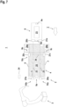
- FIG. 5 shows the driverless transport system 8 after approaching the robot cell 2, so that the surface distance sensors 8. A stop of the driverless Transport system 8 also takes place, of course, when other objects protrude into the protective field 27.
- the driverless transport system 8 sends a request for entry into cell 4.
- the transmitter unit 20b of the light barrier 10b sends its light beams 22 to the receiver unit 21b of the cell 4 on the rear wall 5.
- the receiver unit 21b As soon as the receiver unit 21b has received the light beams 22, it sends corresponding information to the transmitter unit 20a of the light barrier 10a, which then transmits its light beams 22 to the receiver unit 21a of this light barrier 10a on the driverless transport system 8 ( figure 7 ).
- This acknowledgment signal enables the driverless transport system 8 to enter the cell 4 .
- the communication can also take place directly via the control unit 23 .
- an enlarged protective field 25 is monitored with the area distance sensor 9a, which extends up to the front of the driverless transport system 8.
- the protective field 25 is adjusted automatically by the inter-sensor communication.
- the protective field 27 of the area distance sensor 9d is deactivated.
- the protective fields 28a, 28b are monitored with the area distance sensors 9b, 9c.
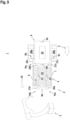
- the protective field 25 is continuously reduced and adapted to the current position of the driverless transport system 8, like the Figures 8 to 11 show.
- the protective field 26 of the light curtain 10c is interrupted ( Figures 9 to 11 ).
- the light rays 22 of the transmitter unit 20a reach the receiver unit 21a of the light barrier 10a and the light rays 22 of the transmitter unit 20b reach the receiver unit 21b of the light barrier 10b.
- the correct retraction of the driverless transport system 8 is checked.
- the robot 3 can continue its work processes.
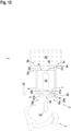
- figure 12 shows driverless transport system 8 when it has moved into its target position in cell 4 .
- the target position is recognized by the fact that the protective field 26 of the light curtain 10c is now free. Then the light barriers 10a, 10b are deactivated.
- a common protective field 28, which includes the area in front of the cell 4, is now monitored with the area distance sensors 9b, 9c, 9e. Access to cell 4 is thus monitored. If the driverless transport system 8 is in the target position, the robot 3 can carry out loading or unloading processes on the driverless transport system 8, as illustrated by the double arrow II.
- the transmitter unit 20b of the light barrier 10b sends light beams 22 to the receiver unit 21b as a request for the driverless transport system 8 to exit from the cell 4 ( figure 13 ).
- the transmitter unit 20a of the light barrier 10a sends light beams 22 to the receiver unit 21a.
- a protective field 29 is activated with the surface distance sensor 9e, with which the rear area of the driverless transport system 8 is monitored. Then the exit of the driverless transport system 8 is released and this moves out of the cell 4 in the direction of the arrow III.
- the protective fields 28a, 28b are activated again for the area distance sensors 9b, 9c ( figure 14 ).
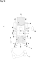
- the exit of the driverless transport system 8 from the cell 4 then takes place in the opposite direction to the entrance with appropriately adapted protective field monitoring, such as that figures 15 , 16 show. During the exit, the protective field 26 of the light curtain 10c is interrupted.
- the robot 3 can be programmed in such a way that it only intervenes in the area above the protective field 25 when the driverless transport system 8 is in the end position according to FIG figure 13 has retracted. In this case, the robot 3 does not need to be notified and does not need to be stopped.
- the robot 3 receives reports about violations of the protective fields 25, 26 and is only stopped or slowed down to a speed that is not dangerous for collisions with people if one of its parts is above or in the protective field 25 or wants to move into this area . Otherwise the robot 3 can continue its movement.
- the protective field 27 in front of the driverless transport system 8 is configured in such a way that the area in front of the driverless transport system 8 is secured with it during a journey as long as the protective field 27 is outside the protective field 25 .
- the driverless transport system 8 then only needs a signal when the protective field 25 is violated in its stopping position ( figure 13 ), not while driving.
- driverless transport system 8 also receives the signal when protective field 25 is violated outside of the stopping position.
- the control unit 23 can then decide according to an internal position-dependent set of rules whether the driverless transport system 8 stops or continues to the stopping position.
Claims (13)
- Dispositif de surveillance (1) comportant des capteurs sur un dispositif fixe et des capteurs sur un dispositif mobile, au moins certains des capteurs étant conçus pour la communication entre le dispositif fixe et le dispositif mobile, et les fonctionnalités de surveillance étant spécifiées d'une manière contrôlée par événement en fonction des signaux des capteurs, caractérisé en ce que les capteurs se voient attribuer des modules de communication par lesquels les informations pour la spécification des fonctionnalités de surveillance peuvent être transmises, en ce que les capteurs échangent des informations directement par l'intermédiaire des modules de communication, et en ce que le dispositif fixe et/ou le dispositif mobile ont une unité de commande (23, 24) avec un module de communication assigné pour échanger des informations entre eux et/ou avec les capteurs, en ce que le dispositif fixe et/ou le dispositif mobile a une unité de commande (23, 24) avec un module de communication associé pour échanger des informations entre eux et/ou avec les capteurs, les signaux de surveillance générés dans les capteurs étant utilisés pour la communication inter-capteurs, et une unité de capteur d'un capteur étant disposée dans chaque cas sur le dispositif fixe et le dispositif mobile, entre lesquels des signaux de surveillance sont transmis qui sont utilisés pour la communication inter-capteurs.
- Dispositif de surveillance (1) selon la revendication 1, caractérisé par le fait qu'il permet de surveiller les zones dangereuses en fonction des événements.
- Dispositif de surveillance (1) selon l'une des revendications 1 ou 2, caractérisé par le fait que les capteurs sont conçus pour la surveillance du champ de protection.
- Dispositif de surveillance (1) selon la revendication 3, caractérisé par le fait que différents champs de protection (25 - 29) pour les capteurs sont prédéterminés en fonction des événements.
- Dispositif de surveillance (1) selon l'une des revendications 3 ou 4, caractérisé par le fait que les champs de protection (25 - 29) sont des zones unidimensionnelles, bidimensionnelles ou tridimensionnelles.
- Dispositif de surveillance (1) selon l'une des revendications 1 à 5, caractérisé par le fait que chaque unité de commande (23, 24) est conçue comme une commande de sécurité et que chaque capteur est conçu comme un capteur de sécurité.
- Dispositif de surveillance (1) selon l'une des revendications 1 à 6, caractérisé par le fait qu'au moins un capteur est un capteur optique ou un capteur radar conçu pour détecter des objets (13) à l'intérieur de champs de protection bidimensionnels et/ou tridimensionnels (25 - 29).
- Dispositif de surveillance (1) selon la revendication 7, caractérisé par le fait qu'au moins un capteur optique est un capteur de distance de surface, un capteur de distance ou un capteur de caméra.
- Dispositif de surveillance (1) selon l'une des revendications 7 ou 8, caractérisé par le fait qu'au moins un capteur est un rideau lumineux (10, 10c) ou une barrière lumineuse (10a, 10b).
- Dispositif de surveillance (1) selon l'une des revendications 1 à 9, caractérisé par le fait que le dispositif fixe est une machine, une installation ou une cellule robotisée (2).
- Dispositif de surveillance (1) selon l'une des revendications 1 à 10, caractérisé par le fait que le dispositif mobile est un véhicule.
- Dispositif de surveillance (1) selon la revendication 11, caractérisé en ce que le véhicule est conçu comme un véhicule autonome.
- Dispositif de surveillance (1) selon l'une des revendications 1 à 12, caractérisé en ce que les modules de communication forment des dispositifs de communication qui sont connectés par des lignes ou fonctionnent sans contact.
Priority Applications (2)
| Application Number | Priority Date | Filing Date | Title |
|---|---|---|---|
| ES19188184T ES2959696T3 (es) | 2019-07-24 | 2019-07-24 | Dispositivo de vigilancia |
| EP19188184.6A EP3770708B1 (fr) | 2019-07-24 | 2019-07-24 | Dispositif de surveillance |
Applications Claiming Priority (1)
| Application Number | Priority Date | Filing Date | Title |
|---|---|---|---|
| EP19188184.6A EP3770708B1 (fr) | 2019-07-24 | 2019-07-24 | Dispositif de surveillance |
Publications (2)
| Publication Number | Publication Date |
|---|---|
| EP3770708A1 EP3770708A1 (fr) | 2021-01-27 |
| EP3770708B1 true EP3770708B1 (fr) | 2023-07-12 |
Family
ID=67438768
Family Applications (1)
| Application Number | Title | Priority Date | Filing Date |
|---|---|---|---|
| EP19188184.6A Active EP3770708B1 (fr) | 2019-07-24 | 2019-07-24 | Dispositif de surveillance |
Country Status (2)
| Country | Link |
|---|---|
| EP (1) | EP3770708B1 (fr) |
| ES (1) | ES2959696T3 (fr) |
Family Cites Families (6)
| Publication number | Priority date | Publication date | Assignee | Title |
|---|---|---|---|---|
| DE10304054B4 (de) * | 2003-02-01 | 2005-03-03 | Leuze Lumiflex Gmbh + Co. Kg | Optischer Sensor |
| DE102006053002B4 (de) * | 2006-11-10 | 2009-05-14 | Leuze Lumiflex Gmbh + Co. Kg | Optischer Sensor |
| DE102015220495A1 (de) * | 2015-10-21 | 2017-04-27 | Kuka Roboter Gmbh | Schutzfeldanpassung eines Manipulatorsystems |
| DE102016107564A1 (de) * | 2016-04-22 | 2017-10-26 | Kuka Systems Gmbh | Sicherheitseinrichtung und Sicherheitsverfahren |
| EP3373093B1 (fr) * | 2017-03-08 | 2019-05-08 | Sick Ag | Système de transport sans conducteur |
| DE102017123295A1 (de) * | 2017-10-06 | 2019-04-11 | Pilz Gmbh & Co. Kg | Sicherheitssystem zur Absicherung eines kooperativen Betriebs von Menschen, Robotern und Maschinen |
-
2019
- 2019-07-24 ES ES19188184T patent/ES2959696T3/es active Active
- 2019-07-24 EP EP19188184.6A patent/EP3770708B1/fr active Active
Also Published As
| Publication number | Publication date |
|---|---|
| ES2959696T3 (es) | 2024-02-27 |
| EP3770708A1 (fr) | 2021-01-27 |
Similar Documents
| Publication | Publication Date | Title |
|---|---|---|
| EP3373093B1 (fr) | Système de transport sans conducteur | |
| EP1781981B1 (fr) | Dispositif et procede de securite pour un robot industriel | |
| EP3365142B1 (fr) | Ajustement du champ de protection d'un système de manipulation | |
| DE102011053212B3 (de) | Optoelektronischer Sensor und Verfahren zur Erfassung von Objekten in einem Überwachungsbereich | |
| EP3791105B1 (fr) | Dispositif et procédé pour sécuriser un appareil mobile à commande mécanique ou automatique et carreau de capteurs | |
| EP3446184B1 (fr) | Dispositif de sécurité et procédé de sécurité | |
| DE10312972B3 (de) | Optischer Sensor | |
| EP3401702B1 (fr) | Système de capteur | |
| EP3910231B1 (fr) | Système de sécurité | |
| AT517784B1 (de) | Verfahren zur automatisierten Steuerung einer Maschinenkomponente | |
| EP3812863B1 (fr) | Machine mobile | |
| EP3770708B1 (fr) | Dispositif de surveillance | |
| DE102006029643B4 (de) | Vorrichtung zur Überwachung eines Gefahrenbereichs | |
| EP2101193A1 (fr) | Système de sécurité destiné à la mesure sans contact de positions, de voies et de vitesses | |
| EP3249476B1 (fr) | Capteur | |
| EP3882505B1 (fr) | Dispositif de surveillance et procédé de fonctionnement d'un dispositif de surveillance | |
| EP3640522A1 (fr) | Dispositif de surveillance | |
| DE202020107300U1 (de) | Sicherheitssystem | |
| DE102017101905A1 (de) | Überwachungseinrichtung | |
| DE102020133787A1 (de) | Sicherheitssystem und Verfahren mit einem Sicherheitssystem | |
| EP3945238B1 (fr) | Dispositif de surveillance et procédé de fonctionnement d'un dispositif de surveillance | |
| DE202020103157U1 (de) | Überwachungseinrichtung | |
| DE202019101201U1 (de) | Überwachungsvorrichtung | |
| EP3757443A1 (fr) | Élément de surveillance et procédé de sécurisation de zones dangereuses | |
| EP3955022A1 (fr) | Agencement de capteurs et son procédé de fonctionnement |
Legal Events
| Date | Code | Title | Description |
|---|---|---|---|
| PUAI | Public reference made under article 153(3) epc to a published international application that has entered the european phase |
Free format text: ORIGINAL CODE: 0009012 |
|
| STAA | Information on the status of an ep patent application or granted ep patent |
Free format text: STATUS: REQUEST FOR EXAMINATION WAS MADE |
|
| 17P | Request for examination filed |
Effective date: 20200325 |
|
| AK | Designated contracting states |
Kind code of ref document: A1 Designated state(s): AL AT BE BG CH CY CZ DE DK EE ES FI FR GB GR HR HU IE IS IT LI LT LU LV MC MK MT NL NO PL PT RO RS SE SI SK SM TR |
|
| AX | Request for extension of the european patent |
Extension state: BA ME |
|
| RIN1 | Information on inventor provided before grant (corrected) |
Inventor name: MORATAL, MARC Inventor name: GALLASTEGUI, INAKI Inventor name: POLO, FRANCISCO |
|
| STAA | Information on the status of an ep patent application or granted ep patent |
Free format text: STATUS: EXAMINATION IS IN PROGRESS |
|
| 17Q | First examination report despatched |
Effective date: 20220615 |
|
| GRAP | Despatch of communication of intention to grant a patent |
Free format text: ORIGINAL CODE: EPIDOSNIGR1 |
|
| STAA | Information on the status of an ep patent application or granted ep patent |
Free format text: STATUS: GRANT OF PATENT IS INTENDED |
|
| GRAS | Grant fee paid |
Free format text: ORIGINAL CODE: EPIDOSNIGR3 |
|
| INTG | Intention to grant announced |
Effective date: 20230328 |
|
| RBV | Designated contracting states (corrected) |
Designated state(s): DE |
|
| GRAA | (expected) grant |
Free format text: ORIGINAL CODE: 0009210 |
|
| STAA | Information on the status of an ep patent application or granted ep patent |
Free format text: STATUS: THE PATENT HAS BEEN GRANTED |
|
| RBV | Designated contracting states (corrected) |
Designated state(s): DE ES FR |
|
| AK | Designated contracting states |
Kind code of ref document: B1 Designated state(s): DE ES FR |
|
| P01 | Opt-out of the competence of the unified patent court (upc) registered |
Effective date: 20230606 |
|
| REG | Reference to a national code |
Ref country code: DE Ref legal event code: R096 Ref document number: 502019008463 Country of ref document: DE |
|
| PGFP | Annual fee paid to national office [announced via postgrant information from national office to epo] |
Ref country code: ES Payment date: 20230927 Year of fee payment: 5 |
|
| PGFP | Annual fee paid to national office [announced via postgrant information from national office to epo] |
Ref country code: FR Payment date: 20230906 Year of fee payment: 5 Ref country code: DE Payment date: 20230706 Year of fee payment: 5 |
|
| REG | Reference to a national code |
Ref country code: ES Ref legal event code: FG2A Ref document number: 2959696 Country of ref document: ES Kind code of ref document: T3 Effective date: 20240227 |