EP3910210A1 - Brake rotor - Google Patents
Brake rotor Download PDFInfo
- Publication number
- EP3910210A1 EP3910210A1 EP21173052.8A EP21173052A EP3910210A1 EP 3910210 A1 EP3910210 A1 EP 3910210A1 EP 21173052 A EP21173052 A EP 21173052A EP 3910210 A1 EP3910210 A1 EP 3910210A1
- Authority
- EP
- European Patent Office
- Prior art keywords
- panel
- flange side
- mounting flanges
- brake rotor
- disposed
- Prior art date
- Legal status (The legal status is an assumption and is not a legal conclusion. Google has not performed a legal analysis and makes no representation as to the accuracy of the status listed.)
- Granted
Links
Images




Classifications
-
- F—MECHANICAL ENGINEERING; LIGHTING; HEATING; WEAPONS; BLASTING
- F16—ENGINEERING ELEMENTS AND UNITS; GENERAL MEASURES FOR PRODUCING AND MAINTAINING EFFECTIVE FUNCTIONING OF MACHINES OR INSTALLATIONS; THERMAL INSULATION IN GENERAL
- F16D—COUPLINGS FOR TRANSMITTING ROTATION; CLUTCHES; BRAKES
- F16D65/00—Parts or details
- F16D65/02—Braking members; Mounting thereof
- F16D65/12—Discs; Drums for disc brakes
- F16D65/123—Discs; Drums for disc brakes comprising an annular disc secured to a hub member; Discs characterised by means for mounting
-
- F—MECHANICAL ENGINEERING; LIGHTING; HEATING; WEAPONS; BLASTING
- F16—ENGINEERING ELEMENTS AND UNITS; GENERAL MEASURES FOR PRODUCING AND MAINTAINING EFFECTIVE FUNCTIONING OF MACHINES OR INSTALLATIONS; THERMAL INSULATION IN GENERAL
- F16D—COUPLINGS FOR TRANSMITTING ROTATION; CLUTCHES; BRAKES
- F16D65/00—Parts or details
- F16D65/02—Braking members; Mounting thereof
- F16D65/12—Discs; Drums for disc brakes
- F16D65/122—Discs; Drums for disc brakes adapted for mounting of friction pads
-
- F—MECHANICAL ENGINEERING; LIGHTING; HEATING; WEAPONS; BLASTING
- F16—ENGINEERING ELEMENTS AND UNITS; GENERAL MEASURES FOR PRODUCING AND MAINTAINING EFFECTIVE FUNCTIONING OF MACHINES OR INSTALLATIONS; THERMAL INSULATION IN GENERAL
- F16D—COUPLINGS FOR TRANSMITTING ROTATION; CLUTCHES; BRAKES
- F16D55/00—Brakes with substantially-radial braking surfaces pressed together in axial direction, e.g. disc brakes
- F16D2055/0004—Parts or details of disc brakes
- F16D2055/0008—Brake supports
-
- F—MECHANICAL ENGINEERING; LIGHTING; HEATING; WEAPONS; BLASTING
- F16—ENGINEERING ELEMENTS AND UNITS; GENERAL MEASURES FOR PRODUCING AND MAINTAINING EFFECTIVE FUNCTIONING OF MACHINES OR INSTALLATIONS; THERMAL INSULATION IN GENERAL
- F16D—COUPLINGS FOR TRANSMITTING ROTATION; CLUTCHES; BRAKES
- F16D65/00—Parts or details
- F16D65/02—Braking members; Mounting thereof
- F16D2065/13—Parts or details of discs or drums
- F16D2065/1304—Structure
- F16D2065/1324—Structure carrying friction elements
-
- F—MECHANICAL ENGINEERING; LIGHTING; HEATING; WEAPONS; BLASTING
- F16—ENGINEERING ELEMENTS AND UNITS; GENERAL MEASURES FOR PRODUCING AND MAINTAINING EFFECTIVE FUNCTIONING OF MACHINES OR INSTALLATIONS; THERMAL INSULATION IN GENERAL
- F16D—COUPLINGS FOR TRANSMITTING ROTATION; CLUTCHES; BRAKES
- F16D65/00—Parts or details
- F16D65/02—Braking members; Mounting thereof
- F16D2065/13—Parts or details of discs or drums
- F16D2065/1304—Structure
- F16D2065/1328—Structure internal cavities, e.g. cooling channels
-
- F—MECHANICAL ENGINEERING; LIGHTING; HEATING; WEAPONS; BLASTING
- F16—ENGINEERING ELEMENTS AND UNITS; GENERAL MEASURES FOR PRODUCING AND MAINTAINING EFFECTIVE FUNCTIONING OF MACHINES OR INSTALLATIONS; THERMAL INSULATION IN GENERAL
- F16D—COUPLINGS FOR TRANSMITTING ROTATION; CLUTCHES; BRAKES
- F16D65/00—Parts or details
- F16D65/02—Braking members; Mounting thereof
- F16D2065/13—Parts or details of discs or drums
- F16D2065/134—Connection
-
- F—MECHANICAL ENGINEERING; LIGHTING; HEATING; WEAPONS; BLASTING
- F16—ENGINEERING ELEMENTS AND UNITS; GENERAL MEASURES FOR PRODUCING AND MAINTAINING EFFECTIVE FUNCTIONING OF MACHINES OR INSTALLATIONS; THERMAL INSULATION IN GENERAL
- F16D—COUPLINGS FOR TRANSMITTING ROTATION; CLUTCHES; BRAKES
- F16D65/00—Parts or details
- F16D65/02—Braking members; Mounting thereof
- F16D2065/13—Parts or details of discs or drums
- F16D2065/134—Connection
- F16D2065/1384—Connection to wheel hub
-
- F—MECHANICAL ENGINEERING; LIGHTING; HEATING; WEAPONS; BLASTING
- F16—ENGINEERING ELEMENTS AND UNITS; GENERAL MEASURES FOR PRODUCING AND MAINTAINING EFFECTIVE FUNCTIONING OF MACHINES OR INSTALLATIONS; THERMAL INSULATION IN GENERAL
- F16D—COUPLINGS FOR TRANSMITTING ROTATION; CLUTCHES; BRAKES
- F16D65/00—Parts or details
- F16D65/02—Braking members; Mounting thereof
- F16D2065/13—Parts or details of discs or drums
- F16D2065/134—Connection
- F16D2065/1392—Connection elements
-
- F—MECHANICAL ENGINEERING; LIGHTING; HEATING; WEAPONS; BLASTING
- F16—ENGINEERING ELEMENTS AND UNITS; GENERAL MEASURES FOR PRODUCING AND MAINTAINING EFFECTIVE FUNCTIONING OF MACHINES OR INSTALLATIONS; THERMAL INSULATION IN GENERAL
- F16D—COUPLINGS FOR TRANSMITTING ROTATION; CLUTCHES; BRAKES
- F16D65/00—Parts or details
- F16D65/78—Features relating to cooling
- F16D2065/788—Internal cooling channels
-
- F—MECHANICAL ENGINEERING; LIGHTING; HEATING; WEAPONS; BLASTING
- F16—ENGINEERING ELEMENTS AND UNITS; GENERAL MEASURES FOR PRODUCING AND MAINTAINING EFFECTIVE FUNCTIONING OF MACHINES OR INSTALLATIONS; THERMAL INSULATION IN GENERAL
- F16D—COUPLINGS FOR TRANSMITTING ROTATION; CLUTCHES; BRAKES
- F16D65/00—Parts or details
- F16D65/005—Components of axially engaging brakes not otherwise provided for
- F16D65/0056—Brake supports
-
- F—MECHANICAL ENGINEERING; LIGHTING; HEATING; WEAPONS; BLASTING
- F16—ENGINEERING ELEMENTS AND UNITS; GENERAL MEASURES FOR PRODUCING AND MAINTAINING EFFECTIVE FUNCTIONING OF MACHINES OR INSTALLATIONS; THERMAL INSULATION IN GENERAL
- F16D—COUPLINGS FOR TRANSMITTING ROTATION; CLUTCHES; BRAKES
- F16D65/00—Parts or details
- F16D65/02—Braking members; Mounting thereof
- F16D65/12—Discs; Drums for disc brakes
- F16D65/128—Discs; Drums for disc brakes characterised by means for cooling
-
- F—MECHANICAL ENGINEERING; LIGHTING; HEATING; WEAPONS; BLASTING
- F16—ENGINEERING ELEMENTS AND UNITS; GENERAL MEASURES FOR PRODUCING AND MAINTAINING EFFECTIVE FUNCTIONING OF MACHINES OR INSTALLATIONS; THERMAL INSULATION IN GENERAL
- F16D—COUPLINGS FOR TRANSMITTING ROTATION; CLUTCHES; BRAKES
- F16D65/00—Parts or details
- F16D65/78—Features relating to cooling
- F16D65/84—Features relating to cooling for disc brakes
- F16D65/847—Features relating to cooling for disc brakes with open cooling system, e.g. cooled by air
Definitions
- This document relates to a brake rotor.
- a brake rotor is disclosed in U.S. Patent No. 10,011,180 .
- a brake rotor may include a first panel, a second panel, a first set of mounting flanges, and a second set of mounting flanges.
- the first and second panels may extend around an axis and may cooperate to at least partially define a rotor opening.
- the first panel may be spaced apart from the second panel.
- the first set of mounting flanges may extend from the first panel into the rotor opening and may be spaced apart from the second panel.
- the second set of mounting flanges may extend from the second panel into the rotor opening and may be spaced apart from the first set of mounting flanges.
- the brake rotor 10 is shown in a partially manufactured state in Figure 1 , such as prior to material removal or finishing operations, and is shown after such operations in Figures 2 and 3 .
- the brake rotor 10 may be a one-piece cast metal component.
- the brake rotor 10 may be provided with a motor vehicle like a truck, bus, farm equipment, military transport or weaponry vehicle, or cargo loading equipment for land, air, or marine vessels or a trailer that may be provided with a motor vehicle. More specifically, the brake rotor 10 may be part of a disc brake that may facilitate braking of a vehicle wheel.
- the brake rotor 10 may be fixedly mountable to a wheel hub that may support the vehicle wheel.
- the brake rotor 10 may be rotatable about an axis 20 with the wheel hub and the vehicle wheel and may provide friction surfaces that facilitate braking.
- the brake rotor 10 may include a first panel 30, a second panel 32, a set of vanes 34. a rotor opening 36, the first set of mounting flanges 38, and a second set of mounting flanges 40.
- the brake rotor 10 may include one or more reinforcement features 42 and one or more tone ring mounts 44.
- the first panel 30 may be configured as a ring that may extend around the axis 20.
- the first panel 30 may have a first friction surface 50, a first interior surface 52, an outer side 54, and an inner side 56.
- the first friction surface 50 may be engaged by friction material of a first brake pad to slow rotation of the brake rotor 10 and an associated wheel about the axis 20.
- the first friction surface 50 may be substantially planar.
- the first friction surface 50 may be disposed substantially perpendicular to the axis 20.
- the first interior surface 52 may be disposed opposite the first friction surface 50.
- the first interior surface 52 may face toward the second panel 32 and may be spaced apart from the second panel 32.
- the first interior surface 52 may be disposed substantially parallel to the first friction surface 50.
- the outer side 54 may face away from the axis 20. In at least one configuration, the outer side 54 may extend from the first friction surface 50 to the first interior surface 52 and may define an outside circumference of the first panel 30. Accordingly, the outer side 54 may extend continuously around the axis 20 and be disposed at a substantially constant radial distance from the axis 20 in one or more configurations.
- the inner side 56 may be disposed opposite the outer side 54. As such, the inner side 56 may face toward the axis 20 and may be disposed closer to the axis 20 and the outer side 54. In at least one configuration, the inner side 56 or a portion thereof may extend from the first friction surface 50 to the first interior surface 52.
- the inner side 56 may be disposed substantially parallel to the outer side 54 and may be disposed at a substantially constant radial distance from the axis 20 in one or more configurations.
- the second panel 32 may be spaced apart from the first panel 30.
- the first panel 30 and the second panel 32 may have substantially similar configurations.
- the first panel 30 and the second panel 32 may have mirror symmetry with respect to a center plane 60, which is best shown in Figure 6 , that may be disposed substantially perpendicular to the axis 20 and that may be disposed between the first panel 30 and the second panel 32.
- the center plane 60 may bisect the brake rotor 10 or may be bisect the gap between the first panel 30 and the second panel 32.
- the second panel 32 may be configured as a ring that may extend around the axis 20 and may have a second friction surface 70, a second interior surface 72, an outer side 74, and an inner side 76.
- the second friction surface 70 may be engaged by friction material of second brake pad to slow rotation of the brake rotor 10 and an associated wheel about the axis 20.
- the second friction surface 70 may face away from the first friction surface 50 and may be substantially planar.
- the second friction surface 70 may be disposed substantially perpendicular to the axis 20 and may be disposed substantially parallel to the first friction surface 50.
- the second interior surface 72 may be disposed opposite the second friction surface 70.
- the second interior surface 72 may face toward the first interior surface 52 of the first panel 30 and may be spaced apart from the first panel 30.
- the second interior surface 72 may be disposed substantially parallel to the second friction surface 70.
- the outer side 74 may face away from the axis 20. In at least one configuration, the outer side 74 may extend from the second friction surface 70 to the second interior surface 72 and may define an outside circumference of the second panel 32. Accordingly, the outer side 74 may extend continuously around the axis 20 and may be disposed at a substantially constant radial distance from the axis 20 and one or more configurations.
- the inner side 76 may be disposed opposite the outer side 74 of the second panel 32. As such, the inner side 76 may face toward the axis 20 and may be disposed closer to the axis 20 and the outer side 74. In at least one configuration, the inner side 76 or a portion thereof may extend from the second friction surface 70 to the second interior surface 72. The inner side 76 may be disposed substantially parallel to the outer side 74 and may be disposed at a substantially constant radial distance from the axis 20 in one or more configurations.
- the set of vanes 34 may extend from the first panel 30 to the second panel 32. More specifically, the vanes 34 may extend from the first interior surface 52 of the first panel 30 to the second interior surface 72 of the second panel 32.
- the vanes 34 may be arranged around the axis 20 in a repeating pattern and may be spaced apart from each other. As such, the vanes 34 may interconnect the first panel 30 with the second panel 32 while providing an air gap between the first panel 30 and the second panel 32 that may facilitate cooling of the brake rotor 10.
- the vanes 34 may extend along radial lines that may extend from the axis 20.
- the vanes 34 may be positioned closer to the axis 20 than the outer sides 54, 74 of the first and second panels 30, 32, respectively, and may be positioned further from the axis 20 than the inner sides 56, 76 of the first and second panels 30, 32, respectively.
- the vanes 34 may be arranged around the first set of mounting flanges 38 and the second set of mounting flanges 40 such that the vanes 34 may be spaced apart from the first set of mounting flanges 38 and the second set of mounting flanges 40.
- the first panel 30 and the second panel 32 may cooperate to at least partially define a rotor opening 36.
- the rotor opening 36 may be a through hole that may extend through the brake rotor 10.
- the rotor opening 36 may be disposed proximate the center of the brake rotor 10 in may be centered about the axis 20.
- the rotor opening 36 may receive a portion of a wheel end assembly, such as a wheel hub.
- the rotor opening 36 may also receive a spindle that may support the wheel hub.
- the first set of mounting flanges 38 may be configured to facilitate positioning and mounting of the brake rotor 10.
- a member of the first set of mounting flanges 38 may be referred to as a first mounting flange.
- Each member of the first set of mounting flanges 38 may extend from the first panel 30 into the rotor opening 36.
- each first mounting flange 38 may extend from the inner side 56 of the first panel 30 toward the axis 20.
- the first set of mounting flanges 38 may be spaced apart from the second panel 32.
- each member of the first set of mounting flanges 38 may include a first flange side 80, a second flange side 82, a first lateral flange side 84, a second lateral flange side 86, an inner flange side 88, and an outer flange side 90.
- the first flange side 80 may face away from the center plane 60 and the second panel 32. In at least one configuration, the first flange side 80 may be offset from the first friction surface 50 and the second friction surface 70 such that the first flange side 80 may be disposed closer to the center plane 60 than the first friction surface 50 and the second friction surface 70.
- the second flange side 82 may be disposed opposite the first flange side 80.
- the first flange side 80 and the second flange side 82 may be disposed on opposite sides of the center plane 60.
- the first flange side 80 and the second flange side 82 may be disposed at substantially the same distances from the center plane 60.
- the second flange side 82 may be disposed substantially parallel to the first flange side 80.
- the second flange side 82 may be offset from the first friction surface 50 and the second friction surface 70 such that the second flange side 82 may be disposed closer to the center plane 60 than the first friction surface 50 and the second friction surface 70.
- the first lateral flange side 84 may extend from the first flange side 80 to the second flange side 82.
- the first lateral flange side 84 may also extend from the inner flange side 88 toward or to the outer flange side 90.
- the second lateral flange side 86 may be disposed opposite the first lateral flange side 84.
- the second lateral flange side 86 may extend from the first flange side 80 to the second flange side 82.
- the second lateral flange side 86 may extend from the inner flange side 88 toward or to the outer flange side 90.
- the second lateral flange side 86 may be disposed in a nonparallel relationship with the first lateral flange side 84.
- the first lateral flange side 84 and the second lateral flange side 86 may be substantially planar.
- the inner flange side 88 may face toward the axis 20.
- the inner flange side 88 may extend from the first flange side 80 to the second flange side 82.
- the inner flange side 88 may extend from the first lateral flange side 84 to the second lateral flange side 86.
- the inner flange side 88 may extend along an arc from the first lateral flange side 84 to the second lateral flange side 86.
- the inner flange side 88 may be disposed at a constant or substantially constant radial distance from the axis 20.
- the outer flange side 90 may be disposed opposite the inner flange side 88. As such, the outer flange side 90 may face away from the axis 20 and may be disposed further away from the axis 20 than the inner flange side 88.
- the outer flange side 90 may extend from the second flange side 82 to the first panel 30. For instance, the outer flange side 90 may extend to the first interior surface 52 of the first panel 30.
- the outer flange side 90 may extend from the first lateral flange side 84 to the second lateral flange side 86.
- the outer flange side 90 may extend from the first panel 30 and may be partially received inside a portion of the rotor opening 36 that is defined by the second panel 32.
- the outer flange side 90 may be disposed in a nonparallel relationship with the inner flange side 88.
- the outer flange side 90 may extend further away from the axis 20 in a direction that extends from the second flange side 82 toward the first flange side 80 or in a direction that extends toward the first panel 30.
- the second set of mounting flanges 40 may also be configured to facilitate positioning and mounting of the brake rotor 10.
- a member of the second set of mounting flanges 40 may be referred to as a second mounting flange.
- Each member of the second set of mounting flanges 40 may extend from the second panel 32 into the rotor opening 36.
- each second mounting flange 40 may extend from the inner side 76 of the second panel 32 toward the axis 20.
- the second set of mounting flanges 40 may be spaced apart from the first panel 30, spaced apart from the first set of mounting flanges 38, or both.
- members of the second set of mounting flanges 40 may have a similar configuration as the members of the first set of mounting flanges 38.
- members of the second set of mounting flanges 40 may include a first flange side 80', a second flange side 82', a first lateral flange side 84', a second lateral flange side 86', an inner flange side 88', and an outer flange side 90'.
- the first flange side 80' may face away from the center plane 60 and the second panel 32. In at least one configuration, the first flange side 80' may be offset from the first friction surface 50 and the second friction surface 70 such that the first flange side 80' may be disposed closer to the center plane 60 than the first friction surface 50 and the second friction surface 70. The first flange side 80' may be coplanar with the first flange side 80.
- the second flange side 82' may be disposed opposite the first flange side 80'.
- the first flange side 80' and the second flange side 82' may be disposed on opposite sides of the center plane 60.
- the first flange side 80' and the second flange side 82' may be disposed at substantially the same distances from the center plane 60.
- the second flange side 82' may be disposed substantially parallel to the first flange side 80'.
- the second flange side 82' may be offset from the first friction surface 50 and the second friction surface 70 such that the second flange side 82' may be disposed closer to the center plane 60 than the first friction surface 50 and the second friction surface 70.
- the second flange side 82 may be coplanar with the second flange side 82'.
- first lateral flange side 84' may extend from the first flange side 80' to the second flange side 82'.
- the first lateral flange side 84' may also extend from the inner flange side 88' toward or to the outer flange side 90'.
- the second lateral flange side 86' may be disposed opposite the first lateral flange side 84'.
- the second lateral flange side 86' may extend from the first flange side 80' to the second flange side 82'.
- the second lateral flange side 86' may extend from the inner flange side 88' toward or to the outer flange side 90'.
- the second lateral flange side 86' may be disposed in a nonparallel relationship with the first lateral flange side 84'.
- the first lateral flange side 84' and the second lateral flange side 86' may be substantially planar.
- the inner flange side 88' may face toward the axis 20.
- the inner flange side 88' may extend from the first flange side 80' to the second flange side 82'.
- the inner flange side 88' may extend from the first lateral flange side 84' to the second lateral flange side 86'.
- the inner flange side 88' may extend along an arc from the first lateral flange side 84' to the second lateral flange side 86'.
- the inner flange side 88' may be disposed at a constant or substantially constant radial distance from the axis 20.
- the outer flange side 90' may be disposed opposite the inner flange side 88'. As such, the outer flange side 90' may face away from the axis 20 and may be disposed further away from the axis 20 than the inner flange side 88'.
- the outer flange side 90' may extend from the first flange side 80' to the second panel 32. For instance, the outer flange side 90' may extend to the second interior surface 72 of the second panel 32.
- the outer flange side 90' may extend from the first lateral flange side 84' to the second lateral flange side 86'.
- the outer flange side 90' may extend from the second panel 32 and may be partially received inside a portion of the rotor opening 36 that is defined by the first panel 30.
- the outer flange side 90' may be disposed in a nonparallel relationship with the inner flange side 88'.
- the outer flange side 90' may extend further away from the axis 20 in a direction that extends from the first flange side 80' toward the second flange side 82' or in a direction that extends toward the second panel 32.
- members of the first set of mounting flanges 38 may be spaced apart from each other and may be spaced apart from one or more members of the second set of mounting flanges 40.
- members of the second set of mounting flanges 40 may be spaced apart from each other and may be spaced apart from one or more members of the first set of mounting flanges 38.
- first set of mounting flanges 38 and the second set of mounting flanges 40 may be provided in various patterns or arrangements.
- first set of mounting flanges 38 and the second set of mounting flanges 40 may be arranged in an alternating pattern around the axis 20, an example of which is show in Figures 2-6 .
- each member of the first set of mounting flanges 38 may be disposed between two different members of the second set of mounting flanges 40.
- each member of the second set of mounting flanges 40 may be disposed between two different members of the first set of mounting flanges 38.
- first lateral flange side 84 of a first mounting flange 38 may face toward the first lateral flange side 84' of a second mounting flange 40 while the second lateral side 86 of a first mounting flange 38 may face toward the second lateral flange side 86' of a second mounting flange 40 as is best shown in Figure 4 .
- first set of mounting flanges 38 and the second set of mounting flanges may be provided in different arrangements.
- a first mounting flange 38 may be disposed adjacent to at least one other first mounting flange 38
- a second mounting flange 40 may be disposed adjacent to at least one other second mounting flange 40, or combinations thereof.
- one or more reinforcement features 42 may optionally be provided with a mounting flange, such as a member of the first set of mounting flanges 38, a member of the second set of mounting flanges 40, or combinations thereof.
- a mounting flange such as a member of the first set of mounting flanges 38, a member of the second set of mounting flanges 40, or combinations thereof.
- one reinforcement feature 42 is provided with each member of the first set of mounting flanges 38 and with each member of the second set of mounting flanges 40.
- a reinforcement feature 42 may extend from a panel, such as the first panel 30, the second panel 32, or both, to a mounting flange, such as a first mounting flange 38 or a second mounting flange 40.
- each reinforcement feature 42 is depicted as extending from the first panel 30; however, it is contemplated that one or more reinforcement features 42 may extend from the second panel 32.
- a reinforcement feature 42 that extends from the first panel 30 may be spaced apart from the second panel 32 and vice versa.
- the reinforcement feature 42 may be disposed in the rotor opening 36.
- the reinforcement feature 42 may extend from a panel toward the axis 20. For instance, the reinforcement feature 42 may extend radially or along a radial line from the first panel 30 toward the axis 20.
- a reinforcement feature 42 that extends from the first panel 30 to a first mounting flange 38 or a second mounting flange 40 may be completely spaced apart from the second panel 32.
- a reinforcement feature 42 that extends from the second panel 32 to a first mounting flange 38 or a second mounting flange 40 may be completely spaced apart from the first panel 30.
- FIG. 7 a section view through reinforcement features 42 provided with a pair of first mounting flanges 38 is shown. In this configuration, these reinforcement features may be completely spaced apart from the second panel 32.
- FIG. 8 a section view through reinforcement features 42 provided with a pair of second mounting flanges 40 is shown.
- these reinforcement features may extend from the first panel 30 to corresponding second mounting flange 40 over a narrow localized area disposed between and spaced apart from the first lateral flange side 84' and the second lateral flange side 86'.
- the second mounting flange 40 may be completely spaced apart from the first panel 30 while a reinforcement feature 42, if provided, may extend from the first panel 30 to a second mounting flange 40. Little thermal energy may be transmitted through the reinforcement feature 42 from the first panel 30 to a corresponding second mounting flange 40.
- one or more mounting holes 100 may be provided with a mounting flange, such as a first mounting flange 38, a second mounting flange 40, or combinations thereof.
- a mounting hole 100 may facilitate mounting of the brake rotor 10 to the hub.
- a mounting hole 100 may receive a fastener, such as a bolt, that may couple the brake rotor 10 to the wheel hub.
- a mounting hole 100 may be configured as a through hole.
- the mounting holes 100 may be arranged around the axis 20 and may be disposed at a substantially constant distance from the axis 20 in one or more configurations.
- a pair of mounting holes 100 is provided with each first mounting flange 38 and with each second mounting flange 40; however, it is contemplated that a greater or lesser number of mounting holes may be provided with some or all mounting flanges.
- the mounting holes 100 are illustrated as being positioned on opposite sides of the reinforcement feature 42. As such, a reinforcement feature 42 may be disposed between adjacent mounting holes 100 in one or more configurations.
- a tone ring mount 44 may facilitate mounting of a tone ring to the brake rotor 10.
- a tone ring may be configured as a ring that may extend continuously around the axis 20 and at least a portion of the rotor opening 36.
- the tone ring may be configured as an encoder disc that may have a plurality of encoder features, such as teeth, that may be arranged in a repeating pattern around the axis 20.
- a sensor may detect rotation of the tone ring and thereby detect rotation of the brake rotor 10 and a corresponding vehicle wheel in a manner known by those the skilled in the art.
- a tone ring mount 44 may have any suitable configuration.
- the tone ring mount 44 may include a fastener hole 110.
- the fastener hole 110 may be configured to receive a fastener, such as a screw or bolt, that may fixedly couple the tone ring to the brake rotor 10.
- the fastener hole 110 may extend from an end surface 112 of the tone ring mount 44.
- a tone ring mount 44 may extend from a reinforcement feature 42 in a direction that extends away from the center plane 60.
- a tone ring mount 44 may extend from a reinforcement feature 42 to an end surface 112.
- the end surface 112 may face away from the center plane 60.
- the tone ring mount 44 and the end surface 112 may protrude in an axial direction past the friction surface of a panel, such as the first friction surface 50 or the second friction surface 70.
- the tone ring mounts 44 protrude past the first panel 30 and the first friction surface 50 such that the end surface 112 may be axially positioned further away from the second panel 32 and the center plane 60 than the first panel 30.
- a tone ring mount 44 may also be spaced apart from a reinforcement feature 42, may not be provided or associated with one or more mounting flanges, or combinations thereof.
- Heating of a brake rotor may be caused by frictional engagement of brake pads with the friction surfaces of the brake rotor.
- Providing a brake rotor with first and second panels that are spaced apart from each other or separated by vanes may help improve dissipation of heat from the brake rotor.
- separating the first and second panels may help reduce the weight of the brake rotor and may permit additional heat dissipation from the region between the first and second panels.
- Providing mounting flanges that extend from one panel, such as a first panel but not a second panel, that extend from one side of a brake rotor, that may be localized on one side of a center plane, or combinations thereof may contribute to temperature differences between the panels, which can lead to rotor coning issues, uneven brake pad wear, and increase thermal stress and potential thermal fractures.
- Providing mounting flanges that extend from each panel such that a mounting flange extends from one panel and is partially or completely separated from another panel of the brake rotor may improve heat dissipation from the brake rotor. For example, heat dissipation from the first panel and the second panel may be better balanced or more equally balanced by separating the mounting flanges associated with the first panel from the second panel and vice versa.
Landscapes
- Engineering & Computer Science (AREA)
- General Engineering & Computer Science (AREA)
- Mechanical Engineering (AREA)
- Braking Arrangements (AREA)
Abstract
Description
- This document relates to a brake rotor.
- A brake rotor is disclosed in
U.S. Patent No. 10,011,180 - In at least one embodiment, a brake rotor is provided. The brake rotor may include a first panel, a second panel, a first set of mounting flanges, and a second set of mounting flanges. The first and second panels may extend around an axis and may cooperate to at least partially define a rotor opening. The first panel may be spaced apart from the second panel. The first set of mounting flanges may extend from the first panel into the rotor opening and may be spaced apart from the second panel. The second set of mounting flanges may extend from the second panel into the rotor opening and may be spaced apart from the first set of mounting flanges.
-
-
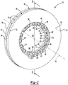
Figure 1 is a perspective view of an example of a brake rotor prior to finishing operations. -
Figures 2 and3 are perspective views of an example of a brake rotor. -
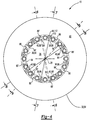
Figure 4 is a side view of the brake rotor ofFigures 2 and3 . -
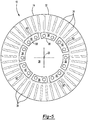
Figure 5 is a section view of the brake rotor along section line 5-5. -
Figure 6 is a section view of the brake rotor along section line 6-6. -
Figure 7 is a section view of the brake rotor along section line 7-7. -
Figure 8 is a section view of the brake rotor along section line 8-8. -
Figure 9 is a section view of the brake rotor along section line 9-9. - As required, detailed embodiments of the present invention are disclosed herein; however, it is to be understood that the disclosed embodiments are merely exemplary of the invention that may be embodied in various and alternative forms. The figures are not necessarily to scale; some features may be exaggerated or minimized to show details of particular components. Therefore, specific structural and functional details disclosed herein are not to be interpreted as limiting, but merely as a representative basis for teaching one skilled in the art to variously employ the present invention.
- Referring to
Figures 1-3 , an example of abrake rotor 10 is shown. Thebrake rotor 10 is shown in a partially manufactured state inFigure 1 , such as prior to material removal or finishing operations, and is shown after such operations inFigures 2 and3 . Thebrake rotor 10 may be a one-piece cast metal component. - The
brake rotor 10 may be provided with a motor vehicle like a truck, bus, farm equipment, military transport or weaponry vehicle, or cargo loading equipment for land, air, or marine vessels or a trailer that may be provided with a motor vehicle. More specifically, thebrake rotor 10 may be part of a disc brake that may facilitate braking of a vehicle wheel. Thebrake rotor 10 may be fixedly mountable to a wheel hub that may support the vehicle wheel. Thebrake rotor 10 may be rotatable about anaxis 20 with the wheel hub and the vehicle wheel and may provide friction surfaces that facilitate braking. In at least one configuration, thebrake rotor 10 may include afirst panel 30, asecond panel 32, a set ofvanes 34. a rotor opening 36, the first set ofmounting flanges 38, and a second set ofmounting flanges 40. Optionally, thebrake rotor 10 may include one ormore reinforcement features 42 and one or moretone ring mounts 44. - Referring primarily to
Figures 2-4 , thefirst panel 30 may be configured as a ring that may extend around theaxis 20. In at least one configuration, thefirst panel 30 may have afirst friction surface 50, a firstinterior surface 52, anouter side 54, and aninner side 56. - The
first friction surface 50 may be engaged by friction material of a first brake pad to slow rotation of thebrake rotor 10 and an associated wheel about theaxis 20. Thefirst friction surface 50 may be substantially planar. In addition, thefirst friction surface 50 may be disposed substantially perpendicular to theaxis 20. - The first
interior surface 52 may be disposed opposite thefirst friction surface 50. The firstinterior surface 52 may face toward thesecond panel 32 and may be spaced apart from thesecond panel 32. The firstinterior surface 52 may be disposed substantially parallel to thefirst friction surface 50. - The
outer side 54 may face away from theaxis 20. In at least one configuration, theouter side 54 may extend from thefirst friction surface 50 to the firstinterior surface 52 and may define an outside circumference of thefirst panel 30. Accordingly, theouter side 54 may extend continuously around theaxis 20 and be disposed at a substantially constant radial distance from theaxis 20 in one or more configurations. - The
inner side 56 may be disposed opposite theouter side 54. As such, theinner side 56 may face toward theaxis 20 and may be disposed closer to theaxis 20 and theouter side 54. In at least one configuration, theinner side 56 or a portion thereof may extend from thefirst friction surface 50 to the firstinterior surface 52. Theinner side 56 may be disposed substantially parallel to theouter side 54 and may be disposed at a substantially constant radial distance from theaxis 20 in one or more configurations. - The
second panel 32 may be spaced apart from thefirst panel 30. Thefirst panel 30 and thesecond panel 32 may have substantially similar configurations. For instance, thefirst panel 30 and thesecond panel 32 may have mirror symmetry with respect to acenter plane 60, which is best shown inFigure 6 , that may be disposed substantially perpendicular to theaxis 20 and that may be disposed between thefirst panel 30 and thesecond panel 32. Thecenter plane 60 may bisect thebrake rotor 10 or may be bisect the gap between thefirst panel 30 and thesecond panel 32. Accordingly, thesecond panel 32 may be configured as a ring that may extend around theaxis 20 and may have asecond friction surface 70, a secondinterior surface 72, anouter side 74, and aninner side 76. - The
second friction surface 70 may be engaged by friction material of second brake pad to slow rotation of thebrake rotor 10 and an associated wheel about theaxis 20. Thesecond friction surface 70 may face away from thefirst friction surface 50 and may be substantially planar. In addition, thesecond friction surface 70 may be disposed substantially perpendicular to theaxis 20 and may be disposed substantially parallel to thefirst friction surface 50. - The second
interior surface 72 may be disposed opposite thesecond friction surface 70. The secondinterior surface 72 may face toward the firstinterior surface 52 of thefirst panel 30 and may be spaced apart from thefirst panel 30. The secondinterior surface 72 may be disposed substantially parallel to thesecond friction surface 70. - The
outer side 74 may face away from theaxis 20. In at least one configuration, theouter side 74 may extend from thesecond friction surface 70 to the secondinterior surface 72 and may define an outside circumference of thesecond panel 32. Accordingly, theouter side 74 may extend continuously around theaxis 20 and may be disposed at a substantially constant radial distance from theaxis 20 and one or more configurations. - The
inner side 76 may be disposed opposite theouter side 74 of thesecond panel 32. As such, theinner side 76 may face toward theaxis 20 and may be disposed closer to theaxis 20 and theouter side 74. In at least one configuration, theinner side 76 or a portion thereof may extend from thesecond friction surface 70 to the secondinterior surface 72. Theinner side 76 may be disposed substantially parallel to theouter side 74 and may be disposed at a substantially constant radial distance from theaxis 20 in one or more configurations. - Referring to
Figures 2 ,5 and6 , the set ofvanes 34 may extend from thefirst panel 30 to thesecond panel 32. More specifically, thevanes 34 may extend from the firstinterior surface 52 of thefirst panel 30 to the secondinterior surface 72 of thesecond panel 32. Thevanes 34 may be arranged around theaxis 20 in a repeating pattern and may be spaced apart from each other. As such, thevanes 34 may interconnect thefirst panel 30 with thesecond panel 32 while providing an air gap between thefirst panel 30 and thesecond panel 32 that may facilitate cooling of thebrake rotor 10. In at least one configuration, thevanes 34 may extend along radial lines that may extend from theaxis 20. Thevanes 34 may be positioned closer to theaxis 20 than theouter sides second panels axis 20 than theinner sides second panels vanes 34 may be arranged around the first set of mountingflanges 38 and the second set of mountingflanges 40 such that thevanes 34 may be spaced apart from the first set of mountingflanges 38 and the second set of mountingflanges 40. - Referring primarily to
Figures 2-4 , thefirst panel 30 and thesecond panel 32 may cooperate to at least partially define arotor opening 36. Therotor opening 36 may be a through hole that may extend through thebrake rotor 10. Therotor opening 36 may be disposed proximate the center of thebrake rotor 10 in may be centered about theaxis 20. Therotor opening 36 may receive a portion of a wheel end assembly, such as a wheel hub. Therotor opening 36 may also receive a spindle that may support the wheel hub. - Referring primarily to
Figures 2-6 , the first set of mountingflanges 38 may be configured to facilitate positioning and mounting of thebrake rotor 10. For convenience in reference, a member of the first set of mountingflanges 38 may be referred to as a first mounting flange. Each member of the first set of mountingflanges 38 may extend from thefirst panel 30 into therotor opening 36. As such, each first mountingflange 38 may extend from theinner side 56 of thefirst panel 30 toward theaxis 20. In addition, the first set of mountingflanges 38 may be spaced apart from thesecond panel 32. In at least one configuration, each member of the first set of mountingflanges 38 may include afirst flange side 80, asecond flange side 82, a firstlateral flange side 84, a secondlateral flange side 86, aninner flange side 88, and anouter flange side 90. - Referring to
Figure 6 , thefirst flange side 80 may face away from thecenter plane 60 and thesecond panel 32. In at least one configuration, thefirst flange side 80 may be offset from thefirst friction surface 50 and thesecond friction surface 70 such that thefirst flange side 80 may be disposed closer to thecenter plane 60 than thefirst friction surface 50 and thesecond friction surface 70. - The
second flange side 82 may be disposed opposite thefirst flange side 80. In at least one configuration, thefirst flange side 80 and thesecond flange side 82 may be disposed on opposite sides of thecenter plane 60. For instance, thefirst flange side 80 and thesecond flange side 82 may be disposed at substantially the same distances from thecenter plane 60. Thesecond flange side 82 may be disposed substantially parallel to thefirst flange side 80. In addition, thesecond flange side 82 may be offset from thefirst friction surface 50 and thesecond friction surface 70 such that thesecond flange side 82 may be disposed closer to thecenter plane 60 than thefirst friction surface 50 and thesecond friction surface 70. - Referring primarily to
Figures 4 and6 , the firstlateral flange side 84 may extend from thefirst flange side 80 to thesecond flange side 82. The firstlateral flange side 84 may also extend from theinner flange side 88 toward or to theouter flange side 90. - The second
lateral flange side 86 may be disposed opposite the firstlateral flange side 84. The secondlateral flange side 86 may extend from thefirst flange side 80 to thesecond flange side 82. In addition, the secondlateral flange side 86 may extend from theinner flange side 88 toward or to theouter flange side 90. In at least one configuration, the secondlateral flange side 86 may be disposed in a nonparallel relationship with the firstlateral flange side 84. The firstlateral flange side 84 and the secondlateral flange side 86 may be substantially planar. - The
inner flange side 88 may face toward theaxis 20. Theinner flange side 88 may extend from thefirst flange side 80 to thesecond flange side 82. In addition, theinner flange side 88 may extend from the firstlateral flange side 84 to the secondlateral flange side 86. In at least one configuration, theinner flange side 88 may extend along an arc from the firstlateral flange side 84 to the secondlateral flange side 86. For instance, theinner flange side 88 may be disposed at a constant or substantially constant radial distance from theaxis 20. - Referring primarily to
Figures 3 and6 , theouter flange side 90 may be disposed opposite theinner flange side 88. As such, theouter flange side 90 may face away from theaxis 20 and may be disposed further away from theaxis 20 than theinner flange side 88. Theouter flange side 90 may extend from thesecond flange side 82 to thefirst panel 30. For instance, theouter flange side 90 may extend to the firstinterior surface 52 of thefirst panel 30. In addition, theouter flange side 90 may extend from the firstlateral flange side 84 to the secondlateral flange side 86. In at least one configuration, theouter flange side 90 may extend from thefirst panel 30 and may be partially received inside a portion of therotor opening 36 that is defined by thesecond panel 32. Theouter flange side 90 may be disposed in a nonparallel relationship with theinner flange side 88. For instance, theouter flange side 90 may extend further away from theaxis 20 in a direction that extends from thesecond flange side 82 toward thefirst flange side 80 or in a direction that extends toward thefirst panel 30. - Referring primarily to
Figures 2-6 , the second set of mountingflanges 40 may also be configured to facilitate positioning and mounting of thebrake rotor 10. For convenience in reference, a member of the second set of mountingflanges 40 may be referred to as a second mounting flange. Each member of the second set of mountingflanges 40 may extend from thesecond panel 32 into therotor opening 36. As such, each second mountingflange 40 may extend from theinner side 76 of thesecond panel 32 toward theaxis 20. In addition, the second set of mountingflanges 40 may be spaced apart from thefirst panel 30, spaced apart from the first set of mountingflanges 38, or both. In at least one configuration, members of the second set of mountingflanges 40 may have a similar configuration as the members of the first set of mountingflanges 38. As such, members of the second set of mountingflanges 40 may include a first flange side 80', asecond flange side 82', a first lateral flange side 84', a second lateral flange side 86', aninner flange side 88', and an outer flange side 90'. - Referring to
Figure 6 , the first flange side 80' may face away from thecenter plane 60 and thesecond panel 32. In at least one configuration, the first flange side 80' may be offset from thefirst friction surface 50 and thesecond friction surface 70 such that the first flange side 80' may be disposed closer to thecenter plane 60 than thefirst friction surface 50 and thesecond friction surface 70. The first flange side 80' may be coplanar with thefirst flange side 80. - The
second flange side 82' may be disposed opposite the first flange side 80'. In at least one configuration, the first flange side 80' and thesecond flange side 82' may be disposed on opposite sides of thecenter plane 60. For instance, the first flange side 80' and thesecond flange side 82' may be disposed at substantially the same distances from thecenter plane 60. Thesecond flange side 82' may be disposed substantially parallel to the first flange side 80'. In addition, thesecond flange side 82' may be offset from thefirst friction surface 50 and thesecond friction surface 70 such that thesecond flange side 82' may be disposed closer to thecenter plane 60 than thefirst friction surface 50 and thesecond friction surface 70. Thesecond flange side 82 may be coplanar with thesecond flange side 82'. - Referring primarily to
Figures 4 and6 , the first lateral flange side 84' may extend from the first flange side 80' to thesecond flange side 82'. The first lateral flange side 84' may also extend from theinner flange side 88' toward or to the outer flange side 90'. - The second lateral flange side 86' may be disposed opposite the first lateral flange side 84'. The second lateral flange side 86' may extend from the first flange side 80' to the
second flange side 82'. In addition, the second lateral flange side 86' may extend from theinner flange side 88' toward or to the outer flange side 90'. In at least one configuration, the second lateral flange side 86' may be disposed in a nonparallel relationship with the first lateral flange side 84'. The first lateral flange side 84' and the second lateral flange side 86' may be substantially planar. - The
inner flange side 88' may face toward theaxis 20. Theinner flange side 88' may extend from the first flange side 80' to thesecond flange side 82'. In addition, theinner flange side 88' may extend from the first lateral flange side 84' to the second lateral flange side 86'. In at least one configuration, theinner flange side 88' may extend along an arc from the first lateral flange side 84' to the second lateral flange side 86'. For instance, theinner flange side 88' may be disposed at a constant or substantially constant radial distance from theaxis 20. - Referring primarily to
Figures 2 and6 , the outer flange side 90' may be disposed opposite theinner flange side 88'. As such, the outer flange side 90' may face away from theaxis 20 and may be disposed further away from theaxis 20 than theinner flange side 88'. The outer flange side 90' may extend from the first flange side 80' to thesecond panel 32. For instance, the outer flange side 90' may extend to the secondinterior surface 72 of thesecond panel 32. In addition, the outer flange side 90' may extend from the first lateral flange side 84' to the second lateral flange side 86'. In at least one configuration, the outer flange side 90' may extend from thesecond panel 32 and may be partially received inside a portion of therotor opening 36 that is defined by thefirst panel 30. The outer flange side 90' may be disposed in a nonparallel relationship with theinner flange side 88'. For instance, the outer flange side 90' may extend further away from theaxis 20 in a direction that extends from the first flange side 80' toward thesecond flange side 82' or in a direction that extends toward thesecond panel 32. - In at least one configuration, members of the first set of mounting
flanges 38 may be spaced apart from each other and may be spaced apart from one or more members of the second set of mountingflanges 40. Similarly, members of the second set of mountingflanges 40 may be spaced apart from each other and may be spaced apart from one or more members of the first set of mountingflanges 38. - The first set of mounting
flanges 38 and the second set of mountingflanges 40 may be provided in various patterns or arrangements. For example, first set of mountingflanges 38 and the second set of mountingflanges 40 may be arranged in an alternating pattern around theaxis 20, an example of which is show inFigures 2-6 . InFigures 2-6 , each member of the first set of mountingflanges 38 may be disposed between two different members of the second set of mountingflanges 40. Similarly, each member of the second set of mountingflanges 40 may be disposed between two different members of the first set of mountingflanges 38. In such an alternating pattern, the firstlateral flange side 84 of a first mountingflange 38 may face toward the first lateral flange side 84' of a second mountingflange 40 while the secondlateral side 86 of a first mountingflange 38 may face toward the second lateral flange side 86' of a second mountingflange 40 as is best shown inFigure 4 . - It is also contemplated that the first set of mounting
flanges 38 and the second set of mounting flanges may be provided in different arrangements. For instance, a first mountingflange 38 may be disposed adjacent to at least one other first mountingflange 38, a second mountingflange 40 may be disposed adjacent to at least one other second mountingflange 40, or combinations thereof. - Referring to
Figures 2 ,4 and6 , one or more reinforcement features 42 may optionally be provided with a mounting flange, such as a member of the first set of mountingflanges 38, a member of the second set of mountingflanges 40, or combinations thereof. In the configuration shown, onereinforcement feature 42 is provided with each member of the first set of mountingflanges 38 and with each member of the second set of mountingflanges 40. - A
reinforcement feature 42 may extend from a panel, such as thefirst panel 30, thesecond panel 32, or both, to a mounting flange, such as a first mountingflange 38 or a second mountingflange 40. In the configuration shown, eachreinforcement feature 42 is depicted as extending from thefirst panel 30; however, it is contemplated that one or more reinforcement features 42 may extend from thesecond panel 32. Areinforcement feature 42 that extends from thefirst panel 30 may be spaced apart from thesecond panel 32 and vice versa. Thereinforcement feature 42 may be disposed in therotor opening 36. In addition, thereinforcement feature 42 may extend from a panel toward theaxis 20. For instance, thereinforcement feature 42 may extend radially or along a radial line from thefirst panel 30 toward theaxis 20. - A
reinforcement feature 42 that extends from thefirst panel 30 to a first mountingflange 38 or a second mountingflange 40 may be completely spaced apart from thesecond panel 32. Conversely, areinforcement feature 42 that extends from thesecond panel 32 to a first mountingflange 38 or a second mountingflange 40 may be completely spaced apart from thefirst panel 30. - Referring to
Figure 7 , a section view through reinforcement features 42 provided with a pair of first mountingflanges 38 is shown. In this configuration, these reinforcement features may be completely spaced apart from thesecond panel 32. - Referring to
Figure 8 , a section view through reinforcement features 42 provided with a pair of second mountingflanges 40 is shown. In this configuration, these reinforcement features may extend from thefirst panel 30 to corresponding second mountingflange 40 over a narrow localized area disposed between and spaced apart from the first lateral flange side 84' and the second lateral flange side 86'. Accordingly, the second mountingflange 40 may be completely spaced apart from thefirst panel 30 while areinforcement feature 42, if provided, may extend from thefirst panel 30 to a second mountingflange 40. Little thermal energy may be transmitted through thereinforcement feature 42 from thefirst panel 30 to a corresponding second mountingflange 40. - Referring to
Figures 2 ,3 and9 , one or more mountingholes 100 may be provided with a mounting flange, such as a first mountingflange 38, a second mountingflange 40, or combinations thereof. A mountinghole 100 may facilitate mounting of thebrake rotor 10 to the hub. For instance, a mountinghole 100 may receive a fastener, such as a bolt, that may couple thebrake rotor 10 to the wheel hub. A mountinghole 100 may be configured as a through hole. The mountingholes 100 may be arranged around theaxis 20 and may be disposed at a substantially constant distance from theaxis 20 in one or more configurations. In the configuration shown, a pair of mountingholes 100 is provided with each first mountingflange 38 and with each second mountingflange 40; however, it is contemplated that a greater or lesser number of mounting holes may be provided with some or all mounting flanges. The mountingholes 100 are illustrated as being positioned on opposite sides of thereinforcement feature 42. As such, areinforcement feature 42 may be disposed between adjacent mountingholes 100 in one or more configurations. - Referring to
Figures 2 ,4 and6 , one or more tone ring mounts 44 may be optionally provided. Atone ring mount 44 may facilitate mounting of a tone ring to thebrake rotor 10. A tone ring may be configured as a ring that may extend continuously around theaxis 20 and at least a portion of therotor opening 36. The tone ring may be configured as an encoder disc that may have a plurality of encoder features, such as teeth, that may be arranged in a repeating pattern around theaxis 20. A sensor may detect rotation of the tone ring and thereby detect rotation of thebrake rotor 10 and a corresponding vehicle wheel in a manner known by those the skilled in the art. Atone ring mount 44 may have any suitable configuration. For instance, thetone ring mount 44 may include afastener hole 110. - The
fastener hole 110 may be configured to receive a fastener, such as a screw or bolt, that may fixedly couple the tone ring to thebrake rotor 10. Thefastener hole 110 may extend from anend surface 112 of thetone ring mount 44. - In at least one configuration, a
tone ring mount 44 may extend from areinforcement feature 42 in a direction that extends away from thecenter plane 60. For instance, atone ring mount 44 may extend from areinforcement feature 42 to anend surface 112. Theend surface 112 may face away from thecenter plane 60. Optionally, thetone ring mount 44 and theend surface 112 may protrude in an axial direction past the friction surface of a panel, such as thefirst friction surface 50 or thesecond friction surface 70. For example, inFigure 6 the tone ring mounts 44 protrude past thefirst panel 30 and thefirst friction surface 50 such that theend surface 112 may be axially positioned further away from thesecond panel 32 and thecenter plane 60 than thefirst panel 30. It is contemplated that atone ring mount 44 may also be spaced apart from areinforcement feature 42, may not be provided or associated with one or more mounting flanges, or combinations thereof. - Heating of a brake rotor may be caused by frictional engagement of brake pads with the friction surfaces of the brake rotor. Providing a brake rotor with first and second panels that are spaced apart from each other or separated by vanes may help improve dissipation of heat from the brake rotor. In addition, separating the first and second panels may help reduce the weight of the brake rotor and may permit additional heat dissipation from the region between the first and second panels.
- Providing mounting flanges that extend from one panel, such as a first panel but not a second panel, that extend from one side of a brake rotor, that may be localized on one side of a center plane, or combinations thereof may contribute to temperature differences between the panels, which can lead to rotor coning issues, uneven brake pad wear, and increase thermal stress and potential thermal fractures. Providing mounting flanges that extend from each panel such that a mounting flange extends from one panel and is partially or completely separated from another panel of the brake rotor may improve heat dissipation from the brake rotor. For example, heat dissipation from the first panel and the second panel may be better balanced or more equally balanced by separating the mounting flanges associated with the first panel from the second panel and vice versa.
- While exemplary embodiments are described above, it is not intended that these embodiments describe all possible forms of the invention. Rather, the words used in the specification are words of description rather than limitation, and it is understood that various changes may be made without departing from the spirit and scope of the invention. Additionally, the features of various implementing embodiments may be combined to form further embodiments of the invention.
Claims (15)
- A brake rotor comprising:a first panel that extends around an axis;a second panel that is spaced apart from the first panel and extends around the axis, wherein the first panel and the second panel cooperate to at least partially define a rotor opening;a first set of mounting flanges that extend from the first panel into the rotor opening and are spaced apart from the second panel; anda second set of mounting flanges that extend from the second panel into the rotor opening, wherein the second set of mounting flanges is spaced apart from the first set of mounting flanges.
- The brake rotor of claim 1 wherein each member of the second set of mounting flanges is spaced apart from the first panel.
- The brake rotor of any preceding claim further comprising a plurality of vanes that extend from the first panel to the second panel and are arranged around the first set of mounting flanges and the second set of mounting flanges, wherein the vanes are spaced apart from the first set of mounting flanges and the second set of mounting flanges.
- The brake rotor of any preceding claim wherein the first set of mounting flanges and the second set of mounting flanges are arranged in an alternating pattern around the axis, preferably each member of the second set of mounting flanges is disposed between two different members of the first set of mounting flanges.
- The brake rotor of any preceding claim wherein a reinforcement feature extends from the first panel to a member of the first set of mounting flanges, wherein the reinforcement feature is spaced apart from the second panel.
- The brake rotor of claim 5 wherein the reinforcement feature is disposed in the rotor opening and extends from the first panel toward the axis.
- The brake rotor of claim 5 or claim 6 wherein the reinforcement feature is disposed between a pair of mounting holes that is provided with the member of the first set of mounting flanges.
- The brake rotor of any one of claims 5 to 7 wherein a tone ring mount extends from the reinforcement feature.
- The brake rotor of any preceding claim wherein each member of the first set of mounting flanges has an inner flange side that faces toward the axis and an outer flange side that is disposed opposite the inner flange side, wherein the outer flange side extends from the first panel and is partially received inside a portion of the rotor opening defined by the second panel, preferably the outer flange side is disposed in a nonparallel relationship with the inner flange side.
- The brake rotor of any preceding claim wherein a reinforcement feature extends from the first panel to a member of the second set of mounting flanges, wherein the reinforcement feature is spaced apart from the second panel.
- The brake rotor of claim 10 wherein the member of the second set of mounting flanges is spaced apart from the first panel.
- The brake rotor of claim 10 or claim 11 wherein the reinforcement feature is disposed in the rotor opening and extends from the first panel toward the axis.
- The brake rotor of claim any one of claims 10 to 12 wherein the reinforcement feature is disposed between a pair of mounting holes that is provided with the member of the second set of mounting flanges.
- The brake rotor of any one of claims 5 to 7 and 10 to 13 wherein a tone ring mount extends from the reinforcement feature, preferably the tone ring mount has an end surface that faces in an axial direction away from the second panel, wherein the tone ring mount protrudes past the first panel such that the end surface is axially positioned further away from the second panel than the first panel.
- The brake rotor of any preceding claim wherein each member of the second set of mounting flanges has an inner flange side that faces toward the axis and an outer flange side that is disposed opposite the inner flange side, wherein the outer flange side extends from the second panel and is partially received inside a portion of the rotor opening defined by the first panel, preferably the outer flange side is disposed in a nonparallel relationship with the inner flange side.
Applications Claiming Priority (1)
| Application Number | Priority Date | Filing Date | Title |
|---|---|---|---|
| IN202011020549 | 2020-05-15 |
Publications (2)
| Publication Number | Publication Date |
|---|---|
| EP3910210A1 true EP3910210A1 (en) | 2021-11-17 |
| EP3910210B1 EP3910210B1 (en) | 2023-12-13 |
Family
ID=75887925
Family Applications (1)
| Application Number | Title | Priority Date | Filing Date |
|---|---|---|---|
| EP21173052.8A Active EP3910210B1 (en) | 2020-05-15 | 2021-05-10 | Brake rotor |
Country Status (3)
| Country | Link |
|---|---|
| US (1) | US11629765B2 (en) |
| EP (1) | EP3910210B1 (en) |
| CN (1) | CN113669392B (en) |
Cited By (2)
| Publication number | Priority date | Publication date | Assignee | Title |
|---|---|---|---|---|
| US20230400073A1 (en) * | 2022-05-24 | 2023-12-14 | Goodrich Corporation | Stator clip for brake assembly |
| US12331801B2 (en) | 2022-05-24 | 2025-06-17 | Goodrich Corporation | Stator clip for brake assembly |
Families Citing this family (4)
| Publication number | Priority date | Publication date | Assignee | Title |
|---|---|---|---|---|
| USD949071S1 (en) * | 2020-06-23 | 2022-04-19 | Sram, Llc | Bicycle brake rotor |
| USD949072S1 (en) * | 2020-06-23 | 2022-04-19 | Sram, Llc | Bicycle brake rotor |
| USD1001027S1 (en) * | 2020-06-23 | 2023-10-10 | Sram, Llc | Bicycle brake rotor |
| US12629963B2 (en) | 2023-11-28 | 2026-05-19 | Arvinmeritor Technology, Llc | Wheel hub and brake rotor assembly |
Citations (6)
| Publication number | Priority date | Publication date | Assignee | Title |
|---|---|---|---|---|
| EP1375953A2 (en) * | 2002-06-12 | 2004-01-02 | Continental Teves AG & Co. oHG | Multi-part brake disc |
| US20050269174A1 (en) * | 2004-06-03 | 2005-12-08 | Warren Lin | Brake rotor |
| EP2604883A2 (en) * | 2011-12-16 | 2013-06-19 | Akebono Brake Industry Co., Ltd. | Composite disc rotor |
| US9303705B2 (en) * | 2014-07-25 | 2016-04-05 | Bendix Spicer Foundation Brake Llc | Brake disc and mounting arrangement for a brake disc |
| US20170074335A1 (en) * | 2015-09-16 | 2017-03-16 | Performance Friction Corporation | Floating rotor disc with compressible retention ring fastener |
| US10011180B2 (en) | 2013-09-30 | 2018-07-03 | Elwha, Llc | Communication and control system and method regarding electric vehicle charging equipment for wireless electric vehicle electrical energy transfer |
Family Cites Families (9)
| Publication number | Priority date | Publication date | Assignee | Title |
|---|---|---|---|---|
| US4501346A (en) * | 1982-03-05 | 1985-02-26 | General Signal Corporation | Disc brake assembly |
| GB0216749D0 (en) * | 2002-07-18 | 2002-08-28 | Meritor Heavy Vehicle Sys Ltd | Brake rotor |
| US20040084261A1 (en) * | 2002-11-01 | 2004-05-06 | Performance Friction Corporation | Brake rotor with a surface having a plurality of indentations formed therein |
| US7934586B1 (en) | 2007-02-27 | 2011-05-03 | Robert Bosch Gmbh | Vented rotor |
| US8336682B2 (en) * | 2007-08-31 | 2012-12-25 | Honda Motor Co., Ltd. | Ventilated brake disk and method |
| US8418817B2 (en) | 2011-06-29 | 2013-04-16 | Arvinmeritor Technology, Llc | Brake assembly having a mounting clip |
| CN204200918U (en) | 2014-08-29 | 2015-03-11 | 长城汽车股份有限公司 | Brake disc and vehicle |
| EP3366491A4 (en) | 2015-10-22 | 2019-05-15 | Iljin Global Co., Ltd. | Wheel bearing assembly |
| US10704602B2 (en) | 2018-05-21 | 2020-07-07 | Arvinmeritor Technology, Llc | Brake rotor and tone ring assembly |
-
2021
- 2021-04-15 US US17/231,733 patent/US11629765B2/en active Active
- 2021-05-10 EP EP21173052.8A patent/EP3910210B1/en active Active
- 2021-05-14 CN CN202110526513.6A patent/CN113669392B/en active Active
Patent Citations (6)
| Publication number | Priority date | Publication date | Assignee | Title |
|---|---|---|---|---|
| EP1375953A2 (en) * | 2002-06-12 | 2004-01-02 | Continental Teves AG & Co. oHG | Multi-part brake disc |
| US20050269174A1 (en) * | 2004-06-03 | 2005-12-08 | Warren Lin | Brake rotor |
| EP2604883A2 (en) * | 2011-12-16 | 2013-06-19 | Akebono Brake Industry Co., Ltd. | Composite disc rotor |
| US10011180B2 (en) | 2013-09-30 | 2018-07-03 | Elwha, Llc | Communication and control system and method regarding electric vehicle charging equipment for wireless electric vehicle electrical energy transfer |
| US9303705B2 (en) * | 2014-07-25 | 2016-04-05 | Bendix Spicer Foundation Brake Llc | Brake disc and mounting arrangement for a brake disc |
| US20170074335A1 (en) * | 2015-09-16 | 2017-03-16 | Performance Friction Corporation | Floating rotor disc with compressible retention ring fastener |
Cited By (3)
| Publication number | Priority date | Publication date | Assignee | Title |
|---|---|---|---|---|
| US20230400073A1 (en) * | 2022-05-24 | 2023-12-14 | Goodrich Corporation | Stator clip for brake assembly |
| US12331801B2 (en) | 2022-05-24 | 2025-06-17 | Goodrich Corporation | Stator clip for brake assembly |
| US12385537B2 (en) * | 2022-05-24 | 2025-08-12 | Goodrich Corporation | Stator clip for brake assembly |
Also Published As
| Publication number | Publication date |
|---|---|
| US11629765B2 (en) | 2023-04-18 |
| EP3910210B1 (en) | 2023-12-13 |
| CN113669392B (en) | 2023-04-28 |
| CN113669392A (en) | 2021-11-19 |
| US20210356007A1 (en) | 2021-11-18 |
Similar Documents
| Publication | Publication Date | Title |
|---|---|---|
| EP3910210B1 (en) | Brake rotor | |
| EP2260215B1 (en) | Outboard hub barrel mounted rotor | |
| EP2066503B1 (en) | Hub device for disc brake, brake disc, and vehicle | |
| US8827054B2 (en) | Brake caliper mounting assembly | |
| US20160298706A1 (en) | Floating Disc Brake Rotor Assemble and Method for Attaching Same | |
| US10781876B2 (en) | Brake disk for vehicles | |
| US9878577B2 (en) | Hub-rotor adapter | |
| US12228186B2 (en) | Wheel end assembly | |
| KR20140010901A (en) | Aluminum flange with anti-rotation slot | |
| CN115366578B (en) | Axle assembly with brake drum | |
| WO2015122148A1 (en) | Railway vehicle wheel with brake discs | |
| US10072717B2 (en) | Driven wheel assembly and automotive vehicle equipped with such an assembly | |
| CN108791484B (en) | Wheel end assembly with compression ring and method of assembly | |
| US6962242B2 (en) | Brake rotor | |
| JPWO2019172367A1 (en) | Rail vehicle brake discs and rail vehicle disc brakes | |
| US20220001693A1 (en) | Brake disc arrangement | |
| US20200166094A1 (en) | Friction ring element, friction ring set for arranging on the wheel web of a track wheel, and track wheel brake | |
| US12629963B2 (en) | Wheel hub and brake rotor assembly | |
| EP1386094B2 (en) | Disk brake for a heavy truck and a vehicle including such a disc brake | |
| CN112606802B (en) | Brake bottom plate assembly, wheel hub assembly, brake shoe, brake drum, dust cover, steering drive axle and vehicle | |
| US20210237506A1 (en) | Fabricated Vehicle Wheel with Wheel Disc Having Lightener Pockets | |
| CA2289833A1 (en) | Rotor assembly for full contact brake | |
| GB2111643A (en) | Mounting brake discs | |
| US20210172485A1 (en) | Commercial vehicle axle with a disc brake |
Legal Events
| Date | Code | Title | Description |
|---|---|---|---|
| PUAI | Public reference made under article 153(3) epc to a published international application that has entered the european phase |
Free format text: ORIGINAL CODE: 0009012 |
|
| STAA | Information on the status of an ep patent application or granted ep patent |
Free format text: STATUS: THE APPLICATION HAS BEEN PUBLISHED |
|
| AK | Designated contracting states |
Kind code of ref document: A1 Designated state(s): AL AT BE BG CH CY CZ DE DK EE ES FI FR GB GR HR HU IE IS IT LI LT LU LV MC MK MT NL NO PL PT RO RS SE SI SK SM TR |
|
| B565 | Issuance of search results under rule 164(2) epc |
Effective date: 20210923 |
|
| STAA | Information on the status of an ep patent application or granted ep patent |
Free format text: STATUS: REQUEST FOR EXAMINATION WAS MADE |
|
| 17P | Request for examination filed |
Effective date: 20220517 |
|
| RBV | Designated contracting states (corrected) |
Designated state(s): AL AT BE BG CH CY CZ DE DK EE ES FI FR GB GR HR HU IE IS IT LI LT LU LV MC MK MT NL NO PL PT RO RS SE SI SK SM TR |
|
| GRAP | Despatch of communication of intention to grant a patent |
Free format text: ORIGINAL CODE: EPIDOSNIGR1 |
|
| STAA | Information on the status of an ep patent application or granted ep patent |
Free format text: STATUS: GRANT OF PATENT IS INTENDED |
|
| INTG | Intention to grant announced |
Effective date: 20230515 |
|
| P01 | Opt-out of the competence of the unified patent court (upc) registered |
Effective date: 20230531 |
|
| GRAJ | Information related to disapproval of communication of intention to grant by the applicant or resumption of examination proceedings by the epo deleted |
Free format text: ORIGINAL CODE: EPIDOSDIGR1 |
|
| STAA | Information on the status of an ep patent application or granted ep patent |
Free format text: STATUS: REQUEST FOR EXAMINATION WAS MADE |
|
| INTC | Intention to grant announced (deleted) | ||
| GRAP | Despatch of communication of intention to grant a patent |
Free format text: ORIGINAL CODE: EPIDOSNIGR1 |
|
| STAA | Information on the status of an ep patent application or granted ep patent |
Free format text: STATUS: GRANT OF PATENT IS INTENDED |
|
| GRAS | Grant fee paid |
Free format text: ORIGINAL CODE: EPIDOSNIGR3 |
|
| GRAA | (expected) grant |
Free format text: ORIGINAL CODE: 0009210 |
|
| STAA | Information on the status of an ep patent application or granted ep patent |
Free format text: STATUS: THE PATENT HAS BEEN GRANTED |
|
| INTG | Intention to grant announced |
Effective date: 20231019 |
|
| AK | Designated contracting states |
Kind code of ref document: B1 Designated state(s): AL AT BE BG CH CY CZ DE DK EE ES FI FR GB GR HR HU IE IS IT LI LT LU LV MC MK MT NL NO PL PT RO RS SE SI SK SM TR |
|
| REG | Reference to a national code |
Ref country code: GB Ref legal event code: FG4D |
|
| REG | Reference to a national code |
Ref country code: CH Ref legal event code: EP |
|
| REG | Reference to a national code |
Ref country code: DE Ref legal event code: R096 Ref document number: 602021007599 Country of ref document: DE |
|
| REG | Reference to a national code |
Ref country code: IE Ref legal event code: FG4D |
|
| REG | Reference to a national code |
Ref country code: SE Ref legal event code: TRGR |
|
| PG25 | Lapsed in a contracting state [announced via postgrant information from national office to epo] |
Ref country code: GR Free format text: LAPSE BECAUSE OF FAILURE TO SUBMIT A TRANSLATION OF THE DESCRIPTION OR TO PAY THE FEE WITHIN THE PRESCRIBED TIME-LIMIT Effective date: 20240314 |
|
| REG | Reference to a national code |
Ref country code: LT Ref legal event code: MG9D |
|
| PG25 | Lapsed in a contracting state [announced via postgrant information from national office to epo] |
Ref country code: LT Free format text: LAPSE BECAUSE OF FAILURE TO SUBMIT A TRANSLATION OF THE DESCRIPTION OR TO PAY THE FEE WITHIN THE PRESCRIBED TIME-LIMIT Effective date: 20231213 |
|
| REG | Reference to a national code |
Ref country code: NL Ref legal event code: MP Effective date: 20231213 |
|
| PG25 | Lapsed in a contracting state [announced via postgrant information from national office to epo] |
Ref country code: ES Free format text: LAPSE BECAUSE OF FAILURE TO SUBMIT A TRANSLATION OF THE DESCRIPTION OR TO PAY THE FEE WITHIN THE PRESCRIBED TIME-LIMIT Effective date: 20231213 |
|
| PG25 | Lapsed in a contracting state [announced via postgrant information from national office to epo] |
Ref country code: LT Free format text: LAPSE BECAUSE OF FAILURE TO SUBMIT A TRANSLATION OF THE DESCRIPTION OR TO PAY THE FEE WITHIN THE PRESCRIBED TIME-LIMIT Effective date: 20231213 Ref country code: GR Free format text: LAPSE BECAUSE OF FAILURE TO SUBMIT A TRANSLATION OF THE DESCRIPTION OR TO PAY THE FEE WITHIN THE PRESCRIBED TIME-LIMIT Effective date: 20240314 Ref country code: ES Free format text: LAPSE BECAUSE OF FAILURE TO SUBMIT A TRANSLATION OF THE DESCRIPTION OR TO PAY THE FEE WITHIN THE PRESCRIBED TIME-LIMIT Effective date: 20231213 Ref country code: BG Free format text: LAPSE BECAUSE OF FAILURE TO SUBMIT A TRANSLATION OF THE DESCRIPTION OR TO PAY THE FEE WITHIN THE PRESCRIBED TIME-LIMIT Effective date: 20240313 |
|
| REG | Reference to a national code |
Ref country code: AT Ref legal event code: MK05 Ref document number: 1640681 Country of ref document: AT Kind code of ref document: T Effective date: 20231213 |
|
| PG25 | Lapsed in a contracting state [announced via postgrant information from national office to epo] |
Ref country code: NL Free format text: LAPSE BECAUSE OF FAILURE TO SUBMIT A TRANSLATION OF THE DESCRIPTION OR TO PAY THE FEE WITHIN THE PRESCRIBED TIME-LIMIT Effective date: 20231213 |
|
| PG25 | Lapsed in a contracting state [announced via postgrant information from national office to epo] |
Ref country code: RS Free format text: LAPSE BECAUSE OF FAILURE TO SUBMIT A TRANSLATION OF THE DESCRIPTION OR TO PAY THE FEE WITHIN THE PRESCRIBED TIME-LIMIT Effective date: 20231213 Ref country code: NO Free format text: LAPSE BECAUSE OF FAILURE TO SUBMIT A TRANSLATION OF THE DESCRIPTION OR TO PAY THE FEE WITHIN THE PRESCRIBED TIME-LIMIT Effective date: 20240313 Ref country code: NL Free format text: LAPSE BECAUSE OF FAILURE TO SUBMIT A TRANSLATION OF THE DESCRIPTION OR TO PAY THE FEE WITHIN THE PRESCRIBED TIME-LIMIT Effective date: 20231213 Ref country code: LV Free format text: LAPSE BECAUSE OF FAILURE TO SUBMIT A TRANSLATION OF THE DESCRIPTION OR TO PAY THE FEE WITHIN THE PRESCRIBED TIME-LIMIT Effective date: 20231213 Ref country code: HR Free format text: LAPSE BECAUSE OF FAILURE TO SUBMIT A TRANSLATION OF THE DESCRIPTION OR TO PAY THE FEE WITHIN THE PRESCRIBED TIME-LIMIT Effective date: 20231213 |
|
| PG25 | Lapsed in a contracting state [announced via postgrant information from national office to epo] |
Ref country code: IS Free format text: LAPSE BECAUSE OF FAILURE TO SUBMIT A TRANSLATION OF THE DESCRIPTION OR TO PAY THE FEE WITHIN THE PRESCRIBED TIME-LIMIT Effective date: 20240413 |
|
| PG25 | Lapsed in a contracting state [announced via postgrant information from national office to epo] |
Ref country code: CZ Free format text: LAPSE BECAUSE OF FAILURE TO SUBMIT A TRANSLATION OF THE DESCRIPTION OR TO PAY THE FEE WITHIN THE PRESCRIBED TIME-LIMIT Effective date: 20231213 Ref country code: AT Free format text: LAPSE BECAUSE OF FAILURE TO SUBMIT A TRANSLATION OF THE DESCRIPTION OR TO PAY THE FEE WITHIN THE PRESCRIBED TIME-LIMIT Effective date: 20231213 |
|
| PG25 | Lapsed in a contracting state [announced via postgrant information from national office to epo] |
Ref country code: SK Free format text: LAPSE BECAUSE OF FAILURE TO SUBMIT A TRANSLATION OF THE DESCRIPTION OR TO PAY THE FEE WITHIN THE PRESCRIBED TIME-LIMIT Effective date: 20231213 |
|
| PG25 | Lapsed in a contracting state [announced via postgrant information from national office to epo] |
Ref country code: SM Free format text: LAPSE BECAUSE OF FAILURE TO SUBMIT A TRANSLATION OF THE DESCRIPTION OR TO PAY THE FEE WITHIN THE PRESCRIBED TIME-LIMIT Effective date: 20231213 Ref country code: SK Free format text: LAPSE BECAUSE OF FAILURE TO SUBMIT A TRANSLATION OF THE DESCRIPTION OR TO PAY THE FEE WITHIN THE PRESCRIBED TIME-LIMIT Effective date: 20231213 Ref country code: RO Free format text: LAPSE BECAUSE OF FAILURE TO SUBMIT A TRANSLATION OF THE DESCRIPTION OR TO PAY THE FEE WITHIN THE PRESCRIBED TIME-LIMIT Effective date: 20231213 Ref country code: IT Free format text: LAPSE BECAUSE OF FAILURE TO SUBMIT A TRANSLATION OF THE DESCRIPTION OR TO PAY THE FEE WITHIN THE PRESCRIBED TIME-LIMIT Effective date: 20231213 Ref country code: IS Free format text: LAPSE BECAUSE OF FAILURE TO SUBMIT A TRANSLATION OF THE DESCRIPTION OR TO PAY THE FEE WITHIN THE PRESCRIBED TIME-LIMIT Effective date: 20240413 Ref country code: EE Free format text: LAPSE BECAUSE OF FAILURE TO SUBMIT A TRANSLATION OF THE DESCRIPTION OR TO PAY THE FEE WITHIN THE PRESCRIBED TIME-LIMIT Effective date: 20231213 Ref country code: CZ Free format text: LAPSE BECAUSE OF FAILURE TO SUBMIT A TRANSLATION OF THE DESCRIPTION OR TO PAY THE FEE WITHIN THE PRESCRIBED TIME-LIMIT Effective date: 20231213 Ref country code: AT Free format text: LAPSE BECAUSE OF FAILURE TO SUBMIT A TRANSLATION OF THE DESCRIPTION OR TO PAY THE FEE WITHIN THE PRESCRIBED TIME-LIMIT Effective date: 20231213 |
|
| PG25 | Lapsed in a contracting state [announced via postgrant information from national office to epo] |
Ref country code: PL Free format text: LAPSE BECAUSE OF FAILURE TO SUBMIT A TRANSLATION OF THE DESCRIPTION OR TO PAY THE FEE WITHIN THE PRESCRIBED TIME-LIMIT Effective date: 20231213 Ref country code: PT Free format text: LAPSE BECAUSE OF FAILURE TO SUBMIT A TRANSLATION OF THE DESCRIPTION OR TO PAY THE FEE WITHIN THE PRESCRIBED TIME-LIMIT Effective date: 20240415 |
|
| PG25 | Lapsed in a contracting state [announced via postgrant information from national office to epo] |
Ref country code: PT Free format text: LAPSE BECAUSE OF FAILURE TO SUBMIT A TRANSLATION OF THE DESCRIPTION OR TO PAY THE FEE WITHIN THE PRESCRIBED TIME-LIMIT Effective date: 20240415 Ref country code: PL Free format text: LAPSE BECAUSE OF FAILURE TO SUBMIT A TRANSLATION OF THE DESCRIPTION OR TO PAY THE FEE WITHIN THE PRESCRIBED TIME-LIMIT Effective date: 20231213 |
|
| REG | Reference to a national code |
Ref country code: DE Ref legal event code: R097 Ref document number: 602021007599 Country of ref document: DE |
|
| PG25 | Lapsed in a contracting state [announced via postgrant information from national office to epo] |
Ref country code: DK Free format text: LAPSE BECAUSE OF FAILURE TO SUBMIT A TRANSLATION OF THE DESCRIPTION OR TO PAY THE FEE WITHIN THE PRESCRIBED TIME-LIMIT Effective date: 20231213 |
|
| PLBE | No opposition filed within time limit |
Free format text: ORIGINAL CODE: 0009261 |
|
| STAA | Information on the status of an ep patent application or granted ep patent |
Free format text: STATUS: NO OPPOSITION FILED WITHIN TIME LIMIT |
|
| PG25 | Lapsed in a contracting state [announced via postgrant information from national office to epo] |
Ref country code: SI Free format text: LAPSE BECAUSE OF FAILURE TO SUBMIT A TRANSLATION OF THE DESCRIPTION OR TO PAY THE FEE WITHIN THE PRESCRIBED TIME-LIMIT Effective date: 20231213 |
|
| PG25 | Lapsed in a contracting state [announced via postgrant information from national office to epo] |
Ref country code: SI Free format text: LAPSE BECAUSE OF FAILURE TO SUBMIT A TRANSLATION OF THE DESCRIPTION OR TO PAY THE FEE WITHIN THE PRESCRIBED TIME-LIMIT Effective date: 20231213 Ref country code: DK Free format text: LAPSE BECAUSE OF FAILURE TO SUBMIT A TRANSLATION OF THE DESCRIPTION OR TO PAY THE FEE WITHIN THE PRESCRIBED TIME-LIMIT Effective date: 20231213 |
|
| 26N | No opposition filed |
Effective date: 20240916 |
|
| REG | Reference to a national code |
Ref country code: CH Ref legal event code: PL |
|
| PG25 | Lapsed in a contracting state [announced via postgrant information from national office to epo] |
Ref country code: MC Free format text: LAPSE BECAUSE OF FAILURE TO SUBMIT A TRANSLATION OF THE DESCRIPTION OR TO PAY THE FEE WITHIN THE PRESCRIBED TIME-LIMIT Effective date: 20231213 |
|
| PG25 | Lapsed in a contracting state [announced via postgrant information from national office to epo] |
Ref country code: LU Free format text: LAPSE BECAUSE OF NON-PAYMENT OF DUE FEES Effective date: 20240510 |
|
| PG25 | Lapsed in a contracting state [announced via postgrant information from national office to epo] |
Ref country code: MC Free format text: LAPSE BECAUSE OF FAILURE TO SUBMIT A TRANSLATION OF THE DESCRIPTION OR TO PAY THE FEE WITHIN THE PRESCRIBED TIME-LIMIT Effective date: 20231213 Ref country code: LU Free format text: LAPSE BECAUSE OF NON-PAYMENT OF DUE FEES Effective date: 20240510 Ref country code: CH Free format text: LAPSE BECAUSE OF NON-PAYMENT OF DUE FEES Effective date: 20240531 |
|
| REG | Reference to a national code |
Ref country code: BE Ref legal event code: MM Effective date: 20240531 |
|
| PG25 | Lapsed in a contracting state [announced via postgrant information from national office to epo] |
Ref country code: IE Free format text: LAPSE BECAUSE OF NON-PAYMENT OF DUE FEES Effective date: 20240510 |
|
| PG25 | Lapsed in a contracting state [announced via postgrant information from national office to epo] |
Ref country code: BE Free format text: LAPSE BECAUSE OF NON-PAYMENT OF DUE FEES Effective date: 20240531 |
|
| PG25 | Lapsed in a contracting state [announced via postgrant information from national office to epo] |
Ref country code: CY Free format text: LAPSE BECAUSE OF FAILURE TO SUBMIT A TRANSLATION OF THE DESCRIPTION OR TO PAY THE FEE WITHIN THE PRESCRIBED TIME-LIMIT; INVALID AB INITIO Effective date: 20210510 |
|
| PG25 | Lapsed in a contracting state [announced via postgrant information from national office to epo] |
Ref country code: HU Free format text: LAPSE BECAUSE OF FAILURE TO SUBMIT A TRANSLATION OF THE DESCRIPTION OR TO PAY THE FEE WITHIN THE PRESCRIBED TIME-LIMIT; INVALID AB INITIO Effective date: 20210510 |
|
| PG25 | Lapsed in a contracting state [announced via postgrant information from national office to epo] |
Ref country code: FI Free format text: LAPSE BECAUSE OF FAILURE TO SUBMIT A TRANSLATION OF THE DESCRIPTION OR TO PAY THE FEE WITHIN THE PRESCRIBED TIME-LIMIT Effective date: 20231213 |
|
| GBPC | Gb: european patent ceased through non-payment of renewal fee |
Effective date: 20250510 |
|
| PG25 | Lapsed in a contracting state [announced via postgrant information from national office to epo] |
Ref country code: GB Free format text: LAPSE BECAUSE OF NON-PAYMENT OF DUE FEES Effective date: 20250510 |
|
| PG25 | Lapsed in a contracting state [announced via postgrant information from national office to epo] |
Ref country code: TR Free format text: LAPSE BECAUSE OF FAILURE TO SUBMIT A TRANSLATION OF THE DESCRIPTION OR TO PAY THE FEE WITHIN THE PRESCRIBED TIME-LIMIT Effective date: 20231213 |
|
| PGFP | Annual fee paid to national office [announced via postgrant information from national office to epo] |
Ref country code: DE Payment date: 20260528 Year of fee payment: 6 |
|
| PGFP | Annual fee paid to national office [announced via postgrant information from national office to epo] |
Ref country code: SE Payment date: 20260527 Year of fee payment: 6 |
|
| PGFP | Annual fee paid to national office [announced via postgrant information from national office to epo] |
Ref country code: FR Payment date: 20260525 Year of fee payment: 6 |