EP3910186A1 - Cylinder head - Google Patents
Cylinder head Download PDFInfo
- Publication number
- EP3910186A1 EP3910186A1 EP19909044.0A EP19909044A EP3910186A1 EP 3910186 A1 EP3910186 A1 EP 3910186A1 EP 19909044 A EP19909044 A EP 19909044A EP 3910186 A1 EP3910186 A1 EP 3910186A1
- Authority
- EP
- European Patent Office
- Prior art keywords
- cylinder head
- intake port
- seal member
- insulation member
- main body
- Prior art date
- Legal status (The legal status is an assumption and is not a legal conclusion. Google has not performed a legal analysis and makes no representation as to the accuracy of the status listed.)
- Granted
Links
Images


Classifications
-
- F—MECHANICAL ENGINEERING; LIGHTING; HEATING; WEAPONS; BLASTING
- F02—COMBUSTION ENGINES; HOT-GAS OR COMBUSTION-PRODUCT ENGINE PLANTS
- F02F—CYLINDERS, PISTONS OR CASINGS, FOR COMBUSTION ENGINES; ARRANGEMENTS OF SEALINGS IN COMBUSTION ENGINES
- F02F1/00—Cylinders; Cylinder heads
- F02F1/24—Cylinder heads
- F02F1/42—Shape or arrangement of intake or exhaust channels in cylinder heads
- F02F1/4235—Shape or arrangement of intake or exhaust channels in cylinder heads of intake channels
-
- F—MECHANICAL ENGINEERING; LIGHTING; HEATING; WEAPONS; BLASTING
- F02—COMBUSTION ENGINES; HOT-GAS OR COMBUSTION-PRODUCT ENGINE PLANTS
- F02F—CYLINDERS, PISTONS OR CASINGS, FOR COMBUSTION ENGINES; ARRANGEMENTS OF SEALINGS IN COMBUSTION ENGINES
- F02F1/00—Cylinders; Cylinder heads
- F02F1/24—Cylinder heads
- F02F1/42—Shape or arrangement of intake or exhaust channels in cylinder heads
- F02F1/4235—Shape or arrangement of intake or exhaust channels in cylinder heads of intake channels
- F02F1/425—Shape or arrangement of intake or exhaust channels in cylinder heads of intake channels with a separate deviation element inside the channel
-
- F—MECHANICAL ENGINEERING; LIGHTING; HEATING; WEAPONS; BLASTING
- F02—COMBUSTION ENGINES; HOT-GAS OR COMBUSTION-PRODUCT ENGINE PLANTS
- F02F—CYLINDERS, PISTONS OR CASINGS, FOR COMBUSTION ENGINES; ARRANGEMENTS OF SEALINGS IN COMBUSTION ENGINES
- F02F1/00—Cylinders; Cylinder heads
- F02F1/24—Cylinder heads
- F02F1/42—Shape or arrangement of intake or exhaust channels in cylinder heads
- F02F1/4235—Shape or arrangement of intake or exhaust channels in cylinder heads of intake channels
- F02F1/4257—Shape or arrangement of intake or exhaust channels in cylinder heads of intake channels with an intake liner
-
- F—MECHANICAL ENGINEERING; LIGHTING; HEATING; WEAPONS; BLASTING
- F02—COMBUSTION ENGINES; HOT-GAS OR COMBUSTION-PRODUCT ENGINE PLANTS
- F02F—CYLINDERS, PISTONS OR CASINGS, FOR COMBUSTION ENGINES; ARRANGEMENTS OF SEALINGS IN COMBUSTION ENGINES
- F02F11/00—Arrangements of sealings in combustion engines
- F02F11/002—Arrangements of sealings in combustion engines involving cylinder heads
-
- Y—GENERAL TAGGING OF NEW TECHNOLOGICAL DEVELOPMENTS; GENERAL TAGGING OF CROSS-SECTIONAL TECHNOLOGIES SPANNING OVER SEVERAL SECTIONS OF THE IPC; TECHNICAL SUBJECTS COVERED BY FORMER USPC CROSS-REFERENCE ART COLLECTIONS [XRACs] AND DIGESTS
- Y02—TECHNOLOGIES OR APPLICATIONS FOR MITIGATION OR ADAPTATION AGAINST CLIMATE CHANGE
- Y02T—CLIMATE CHANGE MITIGATION TECHNOLOGIES RELATED TO TRANSPORTATION
- Y02T10/00—Road transport of goods or passengers
- Y02T10/10—Internal combustion engine [ICE] based vehicles
- Y02T10/12—Improving ICE efficiencies
Definitions
- the cylinder head disclosed herein can enhance the accuracy in registering of an insulation member placed inside the intake port. Therefore, it is possible to avoid both an increase in the air intake resistance caused by resin flowing out of the insulation member and an increase in the air intake resistance caused by a rise of part of the tip of the insulation member in the intake port, thereby contributing to an enhancement in engine performance. Furthermore, since the temperature rise of the intake air can also be suppressed by the insulation member, decrease in the intake air volume and occurrence of knocking can be both suppressed, so that the engine performance can be enhanced.
- FIG. 3 is a cross sectional view showing a structure around the intake port 3 (cross sectional view taken by the line represented the B-B arrows in FIG. 2 ).
- the insulation member 20 is provided on the upstream side of the flow direction of the intake air (hereinafter, simply referred to as "upstream side") and is a portion for widely covering the inner surface of the main body part 11.
- the seal member 21 is an annular member provided continuously with the insulation member 20 on the downstream side of the flow of the intake air (hereinafter, simply referred to as “downstream side”) than the insulation member 20.
- the word “continuously” here represents not only a state of being completely integrated (a state that continues without an interruption), but also a state in which the seal member 21 and the insulation member 20 are seen (as if) to be integrated (including a state in which bubbles adhere to the fixing surface).
- the portion of the main body part 11 from the opening 11a formed on the wall part 1a of the cylinder head main body 10 to the step part 14 is formed in a straight line.
- a non-illustrated intake manifold is connected to the opening 11a of the main body part 11.
- the embodiment may be applied to a cylinder head for an engine except for a cylinder head of a straight four-cylinder engine, or may be applied to a cylinder head for an engine not having both an in-cylinder injection valve and a port-injection valve.
- the present embodiment may be also applied to a cylinder head of an engine that provides one intake valve to every cylinder, a cylinder head that provides two intake valves to every cylinder and that is not bifurcated in the intake port (i.e., one which forms independent ports from the inlet part of the intake port).
- the shape of the intake port is not bifurcated, and the seal member provided to a single intake port consists of one annular part.
- the structure of the intake port 3 described above is an example, and the position of the step part 14 may be different from the position described above.
- the step part may be provided at the upstream side of the bifurcation point 15.
- the expanding part 16 is also not necessary. It is satisfactory that at least the exposed part 12 positioned on the side of the combustion chamber 2, the covered part 13 positioned on the upstream side of the exposed part 12 and covered with the insulation member 20, and the step part 14 positioned at the boundary between the exposed part 12 and the covered part 13 are formed in the intake port 3.
- the sliding mold 30 is assumed to have a shape in which the side molds 34 are also positioned on both sides of the upper mold 31 and the lower mold 32, but the sliding mold 30 may alternatively be one having a center mold having a narrower width and side molds positioned between the upper mold and the lower mold (i.e., only the sides of the center mold).
- a method of manufacturing the cylinder head 1 e.g., the sequence of inserting the sliding mold and the sequence of pulling out the sliding mold
- the shape of the intake port is not undercut, a single-shape mold can be used.
Landscapes
- Engineering & Computer Science (AREA)
- Chemical & Material Sciences (AREA)
- Combustion & Propulsion (AREA)
- Mechanical Engineering (AREA)
- General Engineering & Computer Science (AREA)
- Cylinder Crankcases Of Internal Combustion Engines (AREA)
Abstract
Description
- The present invention relates a cylinder head of an engine.
- A typical cylinder head of an engine is molded by casting with aluminum or an aluminum alloy, for example, and therefore has a relatively high thermal conductivity. Consequently, an intake port communicating with the combustion chamber is heated by heat transferred from the combustion chamber, which causes a temperature rise of the intake air flowing through the intake port. When the temperature of the intake air rises, the intake air volume decreases and knocking tends to occur, which may degrade the engine performance. As one of the solutions to this problem,
Patent Document 1 discloses a structure of an intake passage of an engine, which aims at suppressing a temperature rise of the intake air by arranging a resin insulation member on the inner surface of an intake port, for example. - [Patent Document 1]
Japanese Laid-open Patent Publication No. 2018-3600 - In a structure that places a resin insulation member (resin member) in an intake port of a cylinder head molded with a material such as aluminum as performed in
Patent Document 1 described above, it is essential not to hinder the flow of the intake air by the insulation member. This is because, despite the effort to suppress a rise of an intake air temperature using an insulation member, a possible increase in air intake resistance reduces an advantage of arranging the insulation member. - Further, an example of a method of placing a resin insulation member on the inner surface of the intake port is injection molding as described in above
Patent Document 1. Specifically, the method involves inserting and fixing a mold to the part to be an intake port of a cylinder head molded by casting, and filling a space between the inner surface of this part and the outer surface of the mold with resin. When this method is adopted, it is important to secure the sealing surface so that the resin does not leak out from the space. However, being a casting and having a rough dimensional accuracy, the cylinder head itself problematically has a difficulty in securing the sealing surface. As a solution to this problem, it is conceivable to secure the sealing surface by machining the inner surface of the part to be the intake port, but machining by inserting a tool into a narrow space on the side of the combustion chamber is difficult, considering, for example, a machining time, a machining accuracy, and a machining cost. - With the foregoing problems in view, one of the objects of the cylinder head of the present embodiment is to enhance the accuracy in registering of a resin insulation member to be placed in the intake port and avoids an increase in the air intake resistance. It addition to the above object, an advantageous effect that is derived from each configuration shown in the following detailed modes to carry out the present invention and which is not obtained by the conventional technique can be regarded as another object of the present disclosure.
-
- (1) A cylinder head disclosed herein includes a cylinder head main body having an intake port communicating with a combustion chamber of an engine; and an insulation member being arranged at an inner side of the intake port, made of resin, and formed into an annular shape. A step part is formed at a downstream side of the insulation member in a flow direction of intake air in the intake port such that the intake port has a cross section perpendicular to the flow direction at the downstream side smaller than a cross section perpendicular to the flow direction at an upstream side of the flow direction; and an annular seal member that seals a space between the insulation member and the step part is arranged between the insulation member and the step part.
- (2) The seal member is preferably be an elastic body.
- (3) The seal member and the insulation member are preferably different in material.
- (4) On the cylinder head main body, a communicating hole through which a valve guide is placed is preferably formed so as to communicate with the intake port. In this case, the step part is preferably disposed at an upstream side in the flow direction of an opening of the communicating hole.
- (5) The seal member preferably includes a wall part along an inner face of the intake port under a state where the seal member is fitted into the step part.
- (6) The intake port is preferably formed into a bifurcated shape that communicates with the combustion chamber through two intake valve holes; and the step part is preferably positioned at a bifurcation point at which the intake port bifurcates or at a downstream side in the flow direction of the bifurcation point.
- (7) In the above case (6), the seal member preferably includes two annular parts adapted to fit into the step part in the bifurcated shape and a connecting part that connects the two annular parts.
- (8) In the above case (7), the connecting part is preferably thinner than each of the annular parts.
- The cylinder head disclosed herein can enhance the accuracy in registering of an insulation member placed inside the intake port. Therefore, it is possible to avoid both an increase in the air intake resistance caused by resin flowing out of the insulation member and an increase in the air intake resistance caused by a rise of part of the tip of the insulation member in the intake port, thereby contributing to an enhancement in engine performance. Furthermore, since the temperature rise of the intake air can also be suppressed by the insulation member, decrease in the intake air volume and occurrence of knocking can be both suppressed, so that the engine performance can be enhanced.
-
- [
FIG. 1] FIG. 1 is schematic front view of an intake-side part of a cylinder head according to an embodiment, viewed from the front side of an engine; - [
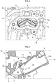
FIG. 2] FIG. 2 is a schematic side view of the cylinder head ofFIG. 1 , viewed from the intake side (seen along A-direction arrow inFIG. 1 ); - [
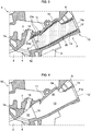
FIG. 3] FIG. 3 is a cross sectional view showing the structure around the intake port of the cylinder head ofFIG. 1 (cross sectional view taken by the line represented by B-B arrows inFIG. 2 ); - [
FIG. 4] FIG. 4 is a cross sectional view showing only a cylinder head main body, imaginary excluding an insulation member from the cross sectional view ofFIG. 3 ; - [
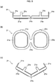
FIG. 5] FIG. 5(a) and FIG. 5(b) are a plan view and a front view of a seal member, andFIG. 5(c) is a plan view showing a state when the seal member is inserted into the intake port; [FIG. 6] FIG. 6 is an enlarged side view showing a state when the seal member shown inFIG. 5(c) is inserted into the intake port; - [
FIG. 7] FIG. 7 is a cross sectional view showing a state where the seal member is fitted in a step part of the intake port shown inFIG. 4 ; - [
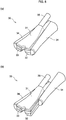
FIG. 8] FIG. 8 is perspective views showing an example of a sliding mold for molding the intake port shown inFIG. 3 ,FIG. 8(a) being a state of being completely assembled,FIG. 8(b) being a state of shifting one side mold; - [
FIG. 9] FIG. 9 is a cross sectional view showing a state of inserting the sliding mold shown inFIG. 8(a) ; and [FIG. 10] FIG. 10 is a cross sectional view showing a state of inserting the sliding mold shown inFIG. 8(a) (cross sectional view corresponding to a cross sectional view taken by the line represented by C-C arrows inFIG. 1 ). - Referring to the drawings, a cylinder head according to an embodiment will now be described. The following embodiment is merely illustrative and is not intended to exclude the application of various modifications and techniques not explicitly described in the embodiment. Each configuration of the present embodiment can be variously modified and implemented without departing from the scope thereof. Besides, the configurations can be each selected or omitted according to the requirement, and can be appropriately combined.
-
FIG. 1 is schematic front view showing an intake-side part of acylinder head 1 according to the embodiment, viewed from the front side of an engine, andFIG. 2 is a schematic side view of the cylinder head 1 (seen along A-direction arrow inFIG. 1 ). Thecylinder head 1 is, for example, a component constituting an engine to be mounted on a vehicle. The present embodiment exemplifies thecylinder head 1 of an engine provided with four cylinders arranged in a row, each of which cylinder has two intake valves and two exhaust valves. Further, the engine of the present embodiment is equipped with an in-cylinder injection valve (not shown) that injects fuel into a combustion chamber 2 (seeFIG. 3 ) and a port injection valve (not shown) that injects fuel into anintake port 3.FIG. 3 is a cross sectional view showing a structure around the intake port 3 (cross sectional view taken by the line represented the B-B arrows inFIG. 2 ). - As shown in
FIGS. 2 and3 , thecylinder head 1 includes a cylinder headmain body 10 molded by casting, for example, aluminum or an aluminum alloy, and aninsulation member 20 and a seal member 21 (seeFIG. 3 ) that are to be detailed below. On thecylinder head 1, theintake port 3, amounting hole 5 for the port injection valve, and amounting hole 6 of the in-cylinder injection valve are formed for each cylinder. Theintake port 3 and themounting holes wall part 1a on the intake side of thecylinder head 1. Further, on thiswall part 1a, a mountingpart 8 to which a delivery pipe connected to the in-cylinder injection valve is fixed, and aninlet 9 for supplying a molten resin to be a resin part 22 (seeFIG. 3 ) that is to be described below are formed. - The cylinder head
main body 10 constitutes the main body part of thecylinder head 1, and as shown inFIGS. 3 and 4 , includes thecombustion chamber 2 and themounting holes intake port 3, for example. FIG. - 4 is a cross sectional view showing only cylinder head
main body 10 excluding theinsulation member 20 and theseal member 21 from the cross sectional view ofFIG. 3 . The main body part 11 (intake port 3) of the present embodiment is formed in a bifurcated shape which communicates with thecombustion chamber 2 via two intake valve holes 4 (seeFIG. 6 ).FIGS. 3 and 4 omit the illustration of a wall part that bifurcates themain body part 11. - On the cylinder head
main body 10 of the present embodiment, a communicatinghole 7 through which a non-illustrated valve guide is inserted and themounting hole 5 for the port injection valve are formed so as to communicate with themain body part 11. Furthermore, on themain body part 11, an expandingpart 16 that widens toward the side (upper side inFIG. 4 ) to which the port injection valve is installed, anopening 5a of the mountinghole 5, and anopening 7a of the communicatinghole 7 are formed. - As shown in
FIG. 3 , theinsulation member 20 is disposed on the inner side of the intake port 3 (along the inner surface of the main body part 11), and is an annular member that suppresses the heat of the cylinder headmain body 10 from transferring to the intake air. Theinsulation member 20 is formed of a resin having lower thermal conductivity than that of the material of the cylinder headmain body 10, and more preferably is formed of a resin having a high heat resistance. For easily grasping, theinsulation member 20 is indicated by being dotted inFIG. 3 . - The
insulation member 20 is provided on the upstream side of the flow direction of the intake air (hereinafter, simply referred to as "upstream side") and is a portion for widely covering the inner surface of themain body part 11. On the other hand, theseal member 21 is an annular member provided continuously with theinsulation member 20 on the downstream side of the flow of the intake air (hereinafter, simply referred to as "downstream side") than theinsulation member 20. The word "continuously" here represents not only a state of being completely integrated (a state that continues without an interruption), but also a state in which theseal member 21 and theinsulation member 20 are seen (as if) to be integrated (including a state in which bubbles adhere to the fixing surface). - The
insulation member 20 and theseal member 21 may be the same or different in material as or from each other. The present embodiment assumes an example in which theinsulation member 20 and theseal member 21 are different in material. In this case, it is preferable that the material of theseal member 21 is more flexible than that of theinsulation member 20. The present embodiment assumes a case where theseal member 21 is a non-metallic elastic body (e.g., resin or rubber). - As shown in
FIG. 3 , theinsulation member 20 is disposed to cover a range of the overall length ofmain body part 11 excluding the portion (i.e., the downstream portion) on the side of thecombustion chamber 2. In other words, themain body part 11 has a portion where theinsulation member 20 is not disposed and a portion where theinsulation member 20 is disposed. Hereinafter, the former portion is called an exposedpart 12, and the latter portion is called acovered part 13. This means that the exposedpart 12 is a portion where the material surface of the cylinder headmain body 10 comes into directly contact with (exposed to) the intake air whereas the coveredpart 13 is a portion where the material surface of the cylinder headmain body 10 is covered with theinsulation member 20 and is out of directly contact with the intake air. Theinsulation member 20 constitutes the inner surface of theintake port 3 in conjunction with the exposedpart 12. - As shown in
FIGS. 3 and 4 , the exposedpart 12 is located on the side of thecombustion chamber 2 of themain body part 11, and the coveredpart 13 is located on the upstream side of the exposedpart 12. The coveredpart 13 is formed to have a cross section (hereinafter, simply referred to as "cross section") perpendicular to the flow direction of the intake air larger than that of the exposedpart 12. With this structure, the boundary between theexposed part 12 and the coveredpart 13, astep part 14 changing the size of its cross section is provided. In other words, on the downstream side of theinsulation member 20 in theintake port 3, thestep part 14 is formed so as to have a size of the cross section coming to be smaller than the upstream side. In the present embodiment, the portion of themain body part 11 from theopening 11a formed on thewall part 1a of the cylinder headmain body 10 to thestep part 14 is formed in a straight line. To theopening 11a of themain body part 11, a non-illustrated intake manifold is connected. - The
step part 14 of the present embodiment is positioned at a bifurcation point 15 (seeFIGS. 4 and6 ) at which the main body part 11 (the intake port 3) bifurcates or at a downstream side of thebifurcation point 15. Further, thestep part 14 is positioned on the upstream side of theopening 7a of the communicatinghole 7 through which a valve guide is inserted. This means that twostep parts 14 are provided in a singlemain body part 11, and eachstep part 14 is provided apart from thecombustion chamber 2. The cylinder headmain body 10 of the present embodiment is narrowed at the end on the side of thewall part 1a of the main body part 11 (i.e., upstream end of the flow direction of the intake air), and a second exposed part 12' on which theinsulation member 20 is not disposed is provided at this narrowed portion. - Here, the structure of the
seal member 21 of the present embodiment will now be detailed. Theseal member 21 is positioned between theinsulation member 20 and thestep part 14 and has a function of sealing therebetween (i.e., sealing the space between theinsulation member 20 and steppart 14 by being in intimate contact with the bothelements 14 and 20). Theseal member 21 of the present embodiment has twoannular parts 21a that are to be fitted in thestep part 14 in the bifurcated shape, and a connectingpart 21b that connects the twoannular parts 21a to each other. -
FIGS. 5(a) and 5(b) are a plan view and a front view showing theseal member 21 having theannular parts 21a taken out from the cylinder headmain body 10, respectively. As shown inFIGS. 5(a) and 5(b) , theseal member 21 of the present embodiment has a structure in which the twoannular parts 21a are connected by a single connectingpart 21b and therefore looks like a shape of eyeglasses. - Each
annular part 21a is an annular portion fitted in thestep part 14 and corresponds to the edge (so-called rim) of the lens when being applied to eyeglasses. Eachannular part 21a has an outer shape coinciding with the cross section of thestep part 14 and has a substantially uniform thickness in the circumferential direction. The twoannular parts 21a are formed in a mirror-symmetric shape and adjoin with a gap between them. The connectingpart 21b is a portion that connects the twoannular parts 21 at the point where the two annular parts come the closest to each other and corresponds to bridges when being applied to eyeglasses. The connectingpart 21b is thinner than each of theannular parts 21a, and as shown inFIG. 5(c) , the connectingpart 21b easily bends in the direction in which the twoannular parts 21a come closer to each other. Alternatively, theseal member 21 may be formed into a more bendable structure by providing a notch that assists the bending to the connectingpart 21b. - The
seal member 21 of the present embodiment is further provided withwall parts 21c extending in the same direction from two points on each of theannular parts 21a. As shown inFIG. 3 , thewall parts 21c serve as portions disposed along the inner face of the coveredpart 13 of theintake port 3 in a state where theseal member 21 is fitted in thestep part 14, and as shown inFIG. 5(c) , extends toward a direction to be the inside when theseal member 21 is bent. Thewall parts 21c have functions of keeping the posture of theseal member 21 when theseal member 21 is installed in themain body part 11, and a function of promoting integration with molten resin when the molten resin that is to serve as theinsulation member 20 is injected. In the illustrated example, theseal member 21 is assumed to have twowall parts 21c provided at 90 degrees apart from each other on eachannular part 21a, but the number and the arrangement of thewall parts 21c are not limited to this. - The thicknesses of the
insulation member 20 and theseal member 21 are set according to the difference (height difference of the step part 14) in the size of the cross section of the coveredpart 13 from the exposedpart 12. This is because if the inner surface of the exposedpart 12 is smoothly connected to the inner surfaces of theinsulation member 20 and theseal member 21, it is possible to avoid an increase in the air intake resistance. That is, when the height difference of thestep part 14 are set to be substantially the same as the thicknesses of theinsulation member 20 and theseal member 21, theinsulation member 20, theseal member 21, and the exposedpart 12 can form a flush inner surface under a state where theseal member 21 is fitted in thestep part 14 and also theinsulation member 20 is disposed on the coveredpart 13. - Next, description will now be made in relation to a method of manufacturing the
cylinder head 1 by arranging theinsulation member 20 and theseal member 21 in themain body part 11 of the above cylinder headmain body 10 with reference toFIGS. 6 to 10 . It should be noted that theseal member 21 having a shape shown inFIGS. 5(a) to 5(c) is prepared in advance. On the other hand, theinsulation member 20 is formed by injection molding carried out after theseal member 21 is placed inside themain body part 11. - First, as shown in
FIG. 6 , theseal member 21 is inserted through theopening 11a of themain body part 11 whichopening 11a is formed onwall part 1a. Since theopening 11a of themain body part 11 is smaller than the cross section in the middle of themain body part 11, theseal member 21 is inserted, being in a folded state as shown inFIG. 5(c) . Then, as shown inFIG. 7 , theseal member 21 is fitted into thestep part 14. - Then, a
mold 30 is inserted through theopening 11a and the tip portion of themold 30 is brought into an intimate contact with theseal member 21. Here, an example of themold 30 is shown inFIGS. 8(a) and 8(b) . Themold 30 of the present embodiment has an outer shape smaller than the inner shape of themain body part 11, and is of a sliding mold formed by combining multiple components divided along a direction (i.e., the flow direction of the intake air) to be inserted into themain body part 11. Specifically, themold 30 includes anupper mold 31 disposed on an upper portion including the expandingpart 16 of themain body part 11, alower mold 32 disposed below theupper mold 31, acenter mold 33 disposed between theupper mold 31 and thelower mold 32,side molds 34 disposed on at least the both sides of thecenter mold 33, and avalve mold 35 inserted into the mountinghole 5. - Here, the
side molds 34 shown inFIGS. 8 (a) and 8(b) are each formed in a shape in contact with the entire both sides of theupper mold 31 and thelower mold 32. As shown inFIG. 8(b) , theside molds 34 are slidably formed with respect to themolds 31 to 33. Further, thecenter mold 33 is slidably formed with respect to both theupper mold 31 and thelower mold 32. Further, thevalve mold 35 is formed in a shape to be fitted to theupper mold 31 and has a function of holding theupper mold 31. - The sequence of inserting the sliding
mold 30 is: first, inserting theupper mold 31 through theopening 11a to be accommodated in the expandingpart 16, and then under this state, inserting thevalve mold 35 through the mountinghole 5 to be fitted to theupper mold 31. Then, thelower mold 32 is inserted through theopening 11a, and thecenter mold 33 is inserted while sliding with respect to theupper mold 31 and thelower mold 32, so that the threemolds 31 to 33 are assembled inside themain body part 11. Finally, by inserting each of the twoside molds 34 while sliding with respect to the threemolds 31 to 33, the slidingmold 30 is made into a state shown inFIG. 10 . As described above, the tip portion of the slidingmold 30 is brought into intimate contact with the member to be serve as theannular part 21. - Then, molten resin that is to serve as the
insulation member 20 is supplied to the inside of themain body part 11 in which the slidingmold 30 is arranged. Since the cylinder headmain body 10 of the present embodiment is provided with theinlets 9 for supplying the molten resin for each cylinder, the molten resin is injected under a state where non-illustrated injections are connected to therespective inlets 9. The molten resin spreads into a space formed between the inner surface of themain body part 11 and the outer surface of the slidingmold 30. - Here, the edge portion on the side of the
combustion chamber 2 in the space where the molten resin spreads is sealed by theseal member 21 fitted in thestep part 14. This avoids leakage of the resin to thecombustion chamber 2. On the other hand, while the slidingmold 30 is placed in themain body part 11, a slight gap is formed between the narrowed portion at the upstream side of themain body part 11 and the slidingmold 30. Although having a function of absorbing the positional deviation of the slidingmold 30, the gap has a possibility of generating leakage of the molten resin. Therefore, on theslide mold 30 of the present embodiment, acomponent 36 for cutting burr is mounted so as to be in an intimate contact with aflange surface 11b (seeFIGS. 6 and9 ) of theopening 11a of themain body part 11. This seals also the edge portion on the side of theopening 11a side in the space where the molten resin spreads, and the leakage of the resin can be avoided. - The molten resin is solidified and integrated with the
seal member 21, so that theinsulation member 20 and theseal member 21 are integrated. After that, the slidingmold 30 is pull out in the reverse order to the order of inserting the slidingmold 30. Specifically, the twoside molds 34 are pulled out by sliding, and then thecenter mold 33 is pulled out. Next, thelower mold 32 is pulled out after being raised to the space formed by pulling out thecenter mold 33. Furthermore, thevalve mold 35 is pulled out and theupper mold 31 is pulled out after being lowered to the space formed by pulling out thecenter mold 33 and thelower mold 32. By pulling out theside molds 34 and thecenter mold 33 first as the above, thelower mold 32 and theupper mold 33 can be pulled out, avoiding possible contact with the inner surface of theinsulation member 20 as much as possible. - (1) Since the
cylinder head 1 described above is provided with thestep part 14 that changes the size of its cross section in theintake port 3 and arranges theseal member 21 that seals the space between thestep part 14 and theinsulation member 20, the accuracy in registering of theinsulation member 20 disposed in theintake port 3 can be increased by theseal member 21, and burrs generated by the molding can be suppressed. Therefore, it is possible to avoid an increase in the air intake resistance resulting from arranging theinsulation member 20 and theseal member 21. - Further, since the
seal member 21 does not protrude into theintake port 3, theinsulation member 20 and the exposedpart 12 of theintake port 3 can be smoothly connected under a state where the step therebetween is reduced as much as possible. This means that since a flush inner surface can be formed, an increase in the air intake resistance due to a partial reduction of the cross-sectional area in theintake port 3 and the increase in the air intake resistance due to rise of part of the tip of theinsulation member 20 inside of theintake port 3 can be both avoided, so that the air volume can be reserved, thereby contributing to the enhancement of the engine performance. - Further, since the temperature rise of the intake air can also be suppressed by the
insulation member 20, decrease in the intake air volume and generation of knocking can be suppressed, so that the engine performance can also be enhanced from this viewpoint. Furthermore, incylinder head 1 described above, theinsulation member 20 is not disposed at the portion close to thecombustion chamber 2 in theintake port 3 and the potion serves as the exposedpart 12. With this structure, even if high-temperature gas enters theintake port 3 by the backflow of the exhaust gas, theinsulation member 20 can be inhibited from being deteriorated. Incidentally, by smoothing the exposedpart 12, even if thecylinder head 1 is used for a long time, it is possible to suppress the deposition of deposits due to the properties of the fuel and lubricating oil, and therefore to suppress the change in combustion performance. - (2) Since the
above seal member 21, which is made of an elastic body, can be easily inserted into themain body part 11 and can be easily crushed when themold 30 is inserted and brought into intimate contact with theseal member 20, theseal member 20 can eliminate the gap by being brought into intimate contact with themold 30. This structure can avoid leakage of the molten resin and can suppress an increase in the air intake resistance caused by theinsulation member 20. If theseal member 21 is made of resin, theseal member 21 is integrated with the molten resin and thereby the air intake resistance can be reduced. - (3) As in the embodiment described above, by forming the
seal member 21 and theinsulation member 20 with respective different materials, it is possible to select materials suitable for the respective roles. For example, it is possible to further enhance the accuracy in registering of theseal member 21 and also achieve a high sealing effectiveness by forming theseal member 21 with an elastic body. In addition, by selecting a material having a high thermal insulation effect for theinsulation member 20, it is possible to arrange theinsulation member 20 having a high thermal insulation effect while avoiding leakage of the molten resin byseal member 21. - (4) Since the
above step part 14 of themain body part 11 is positioned at the upstream side of theopening 7a of the communicatinghole 7 through which the valve guide is inserted, theinsulation member 2 can be inhibited from being deteriorated by being affected by high-temperature gas flowing back from thecombustion chamber 2. - (5) Furthermore, since the
above seal member 21 is provided with thewall parts 21c, the posture of theseal member 21 in a state of being fitted in thestep part 14 can be kept so that the accuracy in registering of theseal member 21 can be further enhanced. In addition, since thewall parts 21c are along the inner surface of the coveredpart 13, theseal member 21 can be easily integrated with theinsulation member 20 via thewall parts 21c. - (6) The above
main body part 11 is formed in a bifurcated shape, and thestep part 14 is located at thebifurcation point 15 of themain body part 11 or at a downstream side of thebifurcation point 15. Since the cross section of thebifurcation point 15 is close to a circular shape, it is possible to apply a load substantially uniformly when theseal member 21 is crushed by inserting themold 30 so that the amount of crushing theseal member 21 can be uniformed. This structure can enhance the effect for avoiding leakage of the molten resin and can suppress an increase in the air intake resistance caused by theinsulation member 20. - (7) Further, in the embodiment described above, there is a shape that the two
annular parts 21a are connected. Specifically, the twoannular parts 21a can be provided simply by fitting thesingle seal member 21 into the twostep parts 14, so that the accuracy in registering thereof can be further enhanced. Further, it is the shape that theannular parts 21a are connected, which makes it possible to less insert theseal member 21 in a wrong posture. - (8) Since the above connecting
part 21b is thinner than each of theannular parts 21a, theseal member 21 can be easily made into a folded state. This makes it possible to easily insert theseal member 21 into themain body part 11, so that theseal member 21 can be easily and precisely fitted into thestep part 14 and the accuracy in registering of theannular parts 21a can be further enhanced. - The above structure of the
cylinder head 1 is an example, and the structure is not limited to this. For example, the embodiment may be applied to a cylinder head for an engine except for a cylinder head of a straight four-cylinder engine, or may be applied to a cylinder head for an engine not having both an in-cylinder injection valve and a port-injection valve. Further alternatively, the present embodiment may be also applied to a cylinder head of an engine that provides one intake valve to every cylinder, a cylinder head that provides two intake valves to every cylinder and that is not bifurcated in the intake port (i.e., one which forms independent ports from the inlet part of the intake port). In this case, the shape of the intake port is not bifurcated, and the seal member provided to a single intake port consists of one annular part. - Further, the embodiment described above assumes that the material of
seal member 21 is an elastic body (e.g., resin or rubber), but the material of theseal member 21 is not limited to an elastic member. Furthermore, theseal member 21 and theinsulation member 20 may be formed of the same material. - The structure of the
intake port 3 described above is an example, and the position of thestep part 14 may be different from the position described above. For example, when theintake port 3 has thebifurcation point 15, the step part may be provided at the upstream side of thebifurcation point 15. In addition, if the engine is not provided with a port injection valve, the expandingpart 16 is also not necessary. It is satisfactory that at least theexposed part 12 positioned on the side of thecombustion chamber 2, the coveredpart 13 positioned on the upstream side of the exposedpart 12 and covered with theinsulation member 20, and thestep part 14 positioned at the boundary between theexposed part 12 and the coveredpart 13 are formed in theintake port 3. - The structure of the
above insulation member 20 is exemplary and is not limited to that described above. It is satisfactory that theinsulation member 20 is at least disposed inside theintake port 3 and is a resin component formed in an annular shape. - The structure of the
above mold 30 described above is merely an example, and is not limited to those described above. The above-described embodiment, the slidingmold 30 is assumed to have a shape in which theside molds 34 are also positioned on both sides of theupper mold 31 and thelower mold 32, but the slidingmold 30 may alternatively be one having a center mold having a narrower width and side molds positioned between the upper mold and the lower mold (i.e., only the sides of the center mold). Further, a method of manufacturing the cylinder head 1 (e.g., the sequence of inserting the sliding mold and the sequence of pulling out the sliding mold) is also an example, and is not limited to one described above. If the shape of the intake port is not undercut, a single-shape mold can be used. -
- 1
- cylinder head
- 2
- combustion chamber
- 3
- intake port
- 4
- intake valve hole
- 7
- communicating hole
- 7a
- opening
- 10
- cylinder head main body
- 11
- main body part
- 12
- exposed part
- 13
- covered part
- 14
- step part
- 15
- bifurcation point
- 20
- insulation member
- 21
- seal member
- 21a
- annular part
- 21b
- connecting part
- 21c
- wall part
- Yav
- average value
Claims (8)
- A cylinder head comprising:a cylinder head main body having an intake port communicating with a combustion chamber of an engine; andan insulation member being arranged at an inner side of the intake port, made of resin, and formed into an annular shape, whereina step part is formed at a downstream side of the insulation member in a flow direction of intake air in the intake port such that the intake port has a cross section perpendicular to the flow direction at the downstream side smaller than a cross section perpendicular to the flow direction at an upstream side of the flow direction; andan annular seal member that seals a space between the insulation member and the step part is arranged between the insulation member and the step part.
- The cylinder head according to claim 1, wherein the seal member is an elastic body.
- The cylinder head according to claim 1 or 2, wherein the seal member and the insulation member are different in material.
- The cylinder head according to any one of claims 1 to 3, whereina communicating hole through which a valve guide is placed is formed on the cylinder head main body so as to communicate with the intake port; andthe step part is disposed at an upstream side in the flow direction of an opening of the communicating hole.
- The cylinder head according to any one of claims 1 to 4, wherein
the seal member comprises a wall part along an inner face of the intake port under a state where the seal member is fitted into the step part. - The cylinder head according to any one of claims 1 to 5, whereinthe intake port is formed into a bifurcated shape that communicates with the combustion chamber through two intake valve holes; andthe step part is positioned at a bifurcation point at which the intake port bifurcates or at a downstream side in the flow direction of the bifurcation point.
- The cylinder head according to claim 6, wherein the seal member comprises two annular parts adapted to fit into the step part in the bifurcated shape and a connecting part that connects the two annular parts.
- The cylinder head according to claim 7, wherein the connecting part is thinner than each of the annular parts.
Applications Claiming Priority (2)
| Application Number | Priority Date | Filing Date | Title |
|---|---|---|---|
| JP2019000829 | 2019-01-07 | ||
| PCT/JP2019/050940 WO2020145153A1 (en) | 2019-01-07 | 2019-12-25 | Cylinder head |
Publications (3)
| Publication Number | Publication Date |
|---|---|
| EP3910186A1 true EP3910186A1 (en) | 2021-11-17 |
| EP3910186A4 EP3910186A4 (en) | 2022-03-02 |
| EP3910186B1 EP3910186B1 (en) | 2026-03-18 |
Family
ID=71520672
Family Applications (1)
| Application Number | Title | Priority Date | Filing Date |
|---|---|---|---|
| EP19909044.0A Active EP3910186B1 (en) | 2019-01-07 | 2019-12-25 | Cylinder head |
Country Status (5)
| Country | Link |
|---|---|
| US (1) | US11530667B2 (en) |
| EP (1) | EP3910186B1 (en) |
| JP (1) | JP7173166B2 (en) |
| CN (1) | CN113272543B (en) |
| WO (1) | WO2020145153A1 (en) |
Families Citing this family (1)
| Publication number | Priority date | Publication date | Assignee | Title |
|---|---|---|---|---|
| EP4314527B1 (en) * | 2021-03-26 | 2024-08-07 | Jaguar Land Rover Limited | Air intake port for a lean-burn gasoline engine |
Family Cites Families (17)
| Publication number | Priority date | Publication date | Assignee | Title |
|---|---|---|---|---|
| JP2526041Y2 (en) * | 1988-11-14 | 1997-02-12 | トヨタ自動車株式会社 | Internal combustion engine intake port |
| US5239956A (en) * | 1991-06-07 | 1993-08-31 | Detroit Diesel Corporation | Internal combustion engine cylinder heads and similar articles of manufacture and methods of manufacturing same |
| JPH0538337U (en) * | 1991-10-23 | 1993-05-25 | 本田技研工業株式会社 | Engine parts with manifold exhaust passage |
| JP3342351B2 (en) * | 1997-06-27 | 2002-11-05 | ダイハツ工業株式会社 | Device for connecting intake pipe to cylinder head in internal combustion engine |
| JP4147938B2 (en) | 2002-12-26 | 2008-09-10 | 日産自動車株式会社 | Intake port structure of internal combustion engine |
| JP4306660B2 (en) * | 2005-08-25 | 2009-08-05 | トヨタ自動車株式会社 | Intake port structure of internal combustion engine |
| JP4655033B2 (en) | 2006-12-13 | 2011-03-23 | トヨタ自動車株式会社 | Internal combustion engine |
| JP2010048249A (en) * | 2008-07-22 | 2010-03-04 | Yamaha Motor Co Ltd | Engine, partition member and method of manufacturing partition member |
| AT511601B1 (en) * | 2011-07-28 | 2013-01-15 | Avl List Gmbh | CYLINDER HEAD WITH LIQUID COOLING |
| JP5513469B2 (en) * | 2011-11-15 | 2014-06-04 | 富士重工業株式会社 | Engine intake system |
| JP6561480B2 (en) * | 2015-01-29 | 2019-08-21 | 三菱自動車工業株式会社 | Engine intake port structure |
| JP6620650B2 (en) * | 2015-05-13 | 2019-12-18 | トヨタ紡織株式会社 | Insulated port parts for internal combustion engines |
| US10639824B2 (en) * | 2015-07-30 | 2020-05-05 | Nissan Motor Co., Ltd. | Die assembly for intake port insert |
| JP6676950B2 (en) * | 2015-12-15 | 2020-04-08 | 三菱自動車工業株式会社 | Insulation structure of intake port |
| JP6729062B2 (en) | 2016-06-27 | 2020-07-22 | 三菱自動車工業株式会社 | Engine intake passage structure |
| JP6471731B2 (en) * | 2016-08-15 | 2019-02-20 | トヨタ自動車株式会社 | Internal combustion engine |
| JP6444352B2 (en) * | 2016-09-29 | 2018-12-26 | 本田技研工業株式会社 | Single cylinder internal combustion engine |
-
2019
- 2019-12-25 JP JP2020565698A patent/JP7173166B2/en active Active
- 2019-12-25 CN CN201980088166.4A patent/CN113272543B/en active Active
- 2019-12-25 EP EP19909044.0A patent/EP3910186B1/en active Active
- 2019-12-25 US US17/420,796 patent/US11530667B2/en active Active
- 2019-12-25 WO PCT/JP2019/050940 patent/WO2020145153A1/en not_active Ceased
Also Published As
| Publication number | Publication date |
|---|---|
| EP3910186A4 (en) | 2022-03-02 |
| EP3910186B1 (en) | 2026-03-18 |
| US20220112859A1 (en) | 2022-04-14 |
| WO2020145153A1 (en) | 2020-07-16 |
| CN113272543B (en) | 2022-12-20 |
| JPWO2020145153A1 (en) | 2021-09-27 |
| CN113272543A (en) | 2021-08-17 |
| JP7173166B2 (en) | 2022-11-16 |
| US11530667B2 (en) | 2022-12-20 |
Similar Documents
| Publication | Publication Date | Title |
|---|---|---|
| JP4400503B2 (en) | Partition plate for intake port, sand core for forming intake port and cylinder head | |
| CN101400462B (en) | Method for manufacturing cylinder head and cylinder head | |
| JP2008249100A (en) | Sealing structure and gasket | |
| JP2014080886A (en) | Exhaust manifold mounting structure for internal combustion engine | |
| EP3910186B1 (en) | Cylinder head | |
| JP4147938B2 (en) | Intake port structure of internal combustion engine | |
| JP4655033B2 (en) | Internal combustion engine | |
| JP2000186615A (en) | Direct injection spark ignition type internal combustion engine | |
| JP2011094515A (en) | Cylinder head block | |
| JP5227374B2 (en) | Spacer | |
| JP7028343B2 (en) | Cylinder head manufacturing method | |
| EP3910187B1 (en) | Cylinder head | |
| JP7028344B2 (en) | Cylinder head manufacturing method | |
| JP2005226579A (en) | Engine exhaust gas recirculation system | |
| JP7136233B2 (en) | cylinder head | |
| JP3665398B2 (en) | Intake manifold integrated structure rocker cover device | |
| JP2007231897A (en) | In-cylinder fuel injection engine | |
| JP7136232B2 (en) | cylinder head | |
| JP6252258B2 (en) | Intake port structure of internal combustion engine | |
| JPWO2020145158A1 (en) | cylinder head | |
| JP2003286915A (en) | Intake device for internal combustion engine |
Legal Events
| Date | Code | Title | Description |
|---|---|---|---|
| STAA | Information on the status of an ep patent application or granted ep patent |
Free format text: STATUS: THE INTERNATIONAL PUBLICATION HAS BEEN MADE |
|
| PUAI | Public reference made under article 153(3) epc to a published international application that has entered the european phase |
Free format text: ORIGINAL CODE: 0009012 |
|
| STAA | Information on the status of an ep patent application or granted ep patent |
Free format text: STATUS: REQUEST FOR EXAMINATION WAS MADE |
|
| 17P | Request for examination filed |
Effective date: 20210723 |
|
| AK | Designated contracting states |
Kind code of ref document: A1 Designated state(s): AL AT BE BG CH CY CZ DE DK EE ES FI FR GB GR HR HU IE IS IT LI LT LU LV MC MK MT NL NO PL PT RO RS SE SI SK SM TR |
|
| A4 | Supplementary search report drawn up and despatched |
Effective date: 20220202 |
|
| RIC1 | Information provided on ipc code assigned before grant |
Ipc: F02F 1/42 20060101ALI20220127BHEP Ipc: F02F 1/24 20060101AFI20220127BHEP |
|
| DAV | Request for validation of the european patent (deleted) | ||
| DAX | Request for extension of the european patent (deleted) | ||
| STAA | Information on the status of an ep patent application or granted ep patent |
Free format text: STATUS: EXAMINATION IS IN PROGRESS |
|
| 17Q | First examination report despatched |
Effective date: 20240219 |
|
| GRAP | Despatch of communication of intention to grant a patent |
Free format text: ORIGINAL CODE: EPIDOSNIGR1 |
|
| STAA | Information on the status of an ep patent application or granted ep patent |
Free format text: STATUS: GRANT OF PATENT IS INTENDED |
|
| INTG | Intention to grant announced |
Effective date: 20251023 |
|
| GRAS | Grant fee paid |
Free format text: ORIGINAL CODE: EPIDOSNIGR3 |
|
| GRAA | (expected) grant |
Free format text: ORIGINAL CODE: 0009210 |
|
| STAA | Information on the status of an ep patent application or granted ep patent |
Free format text: STATUS: THE PATENT HAS BEEN GRANTED |
|
| AK | Designated contracting states |
Kind code of ref document: B1 Designated state(s): AL AT BE BG CH CY CZ DE DK EE ES FI FR GB GR HR HU IE IS IT LI LT LU LV MC MK MT NL NO PL PT RO RS SE SI SK SM TR |
|
| REG | Reference to a national code |
Ref country code: CH Ref legal event code: F10 Free format text: ST27 STATUS EVENT CODE: U-0-0-F10-F00 (AS PROVIDED BY THE NATIONAL OFFICE) Effective date: 20260318 Ref country code: GB Ref legal event code: FG4D |
|
| REG | Reference to a national code |
Ref country code: DE Ref legal event code: R096 Ref document number: 602019082704 Country of ref document: DE |
|
| REG | Reference to a national code |
Ref country code: IE Ref legal event code: FG4D |