EP3910183B1 - Engine emergency stop device of a work vehicle - Google Patents
Engine emergency stop device of a work vehicle Download PDFInfo
- Publication number
- EP3910183B1 EP3910183B1 EP20211964.0A EP20211964A EP3910183B1 EP 3910183 B1 EP3910183 B1 EP 3910183B1 EP 20211964 A EP20211964 A EP 20211964A EP 3910183 B1 EP3910183 B1 EP 3910183B1
- Authority
- EP
- European Patent Office
- Prior art keywords
- operational
- stop
- engine
- hood
- intermediate connecting
- Prior art date
- Legal status (The legal status is an assumption and is not a legal conclusion. Google has not performed a legal analysis and makes no representation as to the accuracy of the status listed.)
- Active
Links
Images


Classifications
-
- F—MECHANICAL ENGINEERING; LIGHTING; HEATING; WEAPONS; BLASTING
- F02—COMBUSTION ENGINES; HOT-GAS OR COMBUSTION-PRODUCT ENGINE PLANTS
- F02D—CONTROLLING COMBUSTION ENGINES
- F02D41/00—Electrical control of supply of combustible mixture or its constituents
- F02D41/02—Circuit arrangements for generating control signals
- F02D41/04—Introducing corrections for particular operating conditions
- F02D41/042—Introducing corrections for particular operating conditions for stopping the engine
-
- A—HUMAN NECESSITIES
- A01—AGRICULTURE; FORESTRY; ANIMAL HUSBANDRY; HUNTING; TRAPPING; FISHING
- A01D—HARVESTING; MOWING
- A01D34/00—Mowers; Mowing apparatus of harvesters
- A01D34/01—Mowers; Mowing apparatus of harvesters characterised by features relating to the type of cutting apparatus
- A01D34/412—Mowers; Mowing apparatus of harvesters characterised by features relating to the type of cutting apparatus having rotating cutters
- A01D34/63—Mowers; Mowing apparatus of harvesters characterised by features relating to the type of cutting apparatus having rotating cutters having cutters rotating about a vertical axis
- A01D34/64—Mowers; Mowing apparatus of harvesters characterised by features relating to the type of cutting apparatus having rotating cutters having cutters rotating about a vertical axis mounted on a vehicle, e.g. a tractor, or drawn by an animal or a vehicle
-
- A—HUMAN NECESSITIES
- A01—AGRICULTURE; FORESTRY; ANIMAL HUSBANDRY; HUNTING; TRAPPING; FISHING
- A01D—HARVESTING; MOWING
- A01D34/00—Mowers; Mowing apparatus of harvesters
- A01D34/01—Mowers; Mowing apparatus of harvesters characterised by features relating to the type of cutting apparatus
- A01D34/412—Mowers; Mowing apparatus of harvesters characterised by features relating to the type of cutting apparatus having rotating cutters
- A01D34/63—Mowers; Mowing apparatus of harvesters characterised by features relating to the type of cutting apparatus having rotating cutters having cutters rotating about a vertical axis
- A01D34/82—Other details
- A01D34/828—Safety devices
-
- F—MECHANICAL ENGINEERING; LIGHTING; HEATING; WEAPONS; BLASTING
- F02—COMBUSTION ENGINES; HOT-GAS OR COMBUSTION-PRODUCT ENGINE PLANTS
- F02D—CONTROLLING COMBUSTION ENGINES
- F02D11/00—Arrangements for, or adaptations to, non-automatic engine control initiation means, e.g. operator initiated
- F02D11/02—Arrangements for, or adaptations to, non-automatic engine control initiation means, e.g. operator initiated characterised by hand, foot, or like operator controlled initiation means
-
- F—MECHANICAL ENGINEERING; LIGHTING; HEATING; WEAPONS; BLASTING
- F02—COMBUSTION ENGINES; HOT-GAS OR COMBUSTION-PRODUCT ENGINE PLANTS
- F02D—CONTROLLING COMBUSTION ENGINES
- F02D17/00—Controlling engines by cutting out individual cylinders; Rendering engines inoperative or idling
- F02D17/04—Controlling engines by cutting out individual cylinders; Rendering engines inoperative or idling rendering engines inoperative or idling, e.g. caused by abnormal conditions
-
- F—MECHANICAL ENGINEERING; LIGHTING; HEATING; WEAPONS; BLASTING
- F02—COMBUSTION ENGINES; HOT-GAS OR COMBUSTION-PRODUCT ENGINE PLANTS
- F02D—CONTROLLING COMBUSTION ENGINES
- F02D41/00—Electrical control of supply of combustible mixture or its constituents
- F02D41/22—Safety or indicating devices for abnormal conditions
-
- F—MECHANICAL ENGINEERING; LIGHTING; HEATING; WEAPONS; BLASTING
- F02—COMBUSTION ENGINES; HOT-GAS OR COMBUSTION-PRODUCT ENGINE PLANTS
- F02M—SUPPLYING COMBUSTION ENGINES IN GENERAL WITH COMBUSTIBLE MIXTURES OR CONSTITUENTS THEREOF
- F02M63/00—Other fuel-injection apparatus having pertinent characteristics not provided for in groups F02M39/00 - F02M57/00 or F02M67/00; Details, component parts, or accessories of fuel-injection apparatus, not provided for in, or of interest apart from, the apparatus of groups F02M39/00 - F02M61/00 or F02M67/00; Combination of fuel pump with other devices, e.g. lubricating oil pump
- F02M63/02—Fuel-injection apparatus having several injectors fed by a common pumping element, or having several pumping elements feeding a common injector; Fuel-injection apparatus having provisions for cutting-out pumps, pumping elements, or injectors; Fuel-injection apparatus having provisions for variably interconnecting pumping elements and injectors alternatively
- F02M63/0205—Fuel-injection apparatus having several injectors fed by a common pumping element, or having several pumping elements feeding a common injector; Fuel-injection apparatus having provisions for cutting-out pumps, pumping elements, or injectors; Fuel-injection apparatus having provisions for variably interconnecting pumping elements and injectors alternatively for cutting-out pumps or injectors in case of abnormal operation of the engine or the injection apparatus, e.g. over-speed, break-down of fuel pumps or injectors ; for cutting-out pumps for stopping the engine
- F02M63/0215—Fuel-injection apparatus having several injectors fed by a common pumping element, or having several pumping elements feeding a common injector; Fuel-injection apparatus having provisions for cutting-out pumps, pumping elements, or injectors; Fuel-injection apparatus having provisions for variably interconnecting pumping elements and injectors alternatively for cutting-out pumps or injectors in case of abnormal operation of the engine or the injection apparatus, e.g. over-speed, break-down of fuel pumps or injectors ; for cutting-out pumps for stopping the engine by draining or closing fuel conduits
Definitions
- the present invention relates to an engine emergency stop device of a work vehicle configured such that an emergency stop of an engine is possible via a stop operational mechanism configured to communicate a stop command provided by a stop command operational tool provided separately of a key switch and outside a hood to an engine stop lever separately of the key switch.
- a manual stop operational system is employed to manually operate an engine stop tool to stop fuel supply from a fuel injection pump, thus stopping the engine (see Patent Document 1 for example).
- Patent Document 1 Japanese Utility Model Application Publication No. Hei. 2-110238 .
- an engine stop tool for controlling feeding/discharging of fuel to/from the fuel injection pump. And, this engine stop tool is operably interlocked with the electric stop operational system using the stopping motor and a manual stop operational system using a stop operational mechanism so that it is possible to pivotally operate a stop lever to control feeding/discharging of fuel not only by the key switch, but also by a manual stop command operational tool provided separately of the key switch.
- the engine can yet be stopped by a manual operation.
- the arrangement is advantageous.
- the present invention is intended to utilize an engine emergency stop device having a stop operational mechanism commonly usable for various machine types differing in the disposing position or operational direction of a stop lever for engine stop which is disposed inside a hood.
- An engine emergency stop device of a work vehicle comprises:
- a stop command operational tool provided outside the hood is connected to the stop lever via the stop operational mechanism.
- This stop operational mechanism includes a starting end operational portion for transmitting an operational force along an operational direction of the stop command operational tool, a terminal end operational portion for transmitting the operational force of the stop command operational tool along an operational direction of the stop lever, and an intermediate connecting portion connecting the starting end operational portion with the terminal end operational portion. Therefore, even when an engine stop is not possible by the key switch, the engine stop is made still possible by a manual operation by manually operating the stop command operational tool.
- the intermediate connecting portion compensates for an error between the starting end operational portion and the terminal end operational portion in the operational direction or the operational position to operate the terminal end operational portion toward the engine stopping side in association with an operation of the starting end operational portion toward the engine stopping side. Therefore, with appropriate adjustment at the intermediate connecting portion of an amount of error present in the operational direction or the operational position, the stop lever at the corresponding position can be manually operated toward the engine stopping side.
- the intermediate connecting portion is provided at a plurality of portions in the stop operational mechanism.
- the intermediate connecting portion is provided at a plurality of portions, there is obtained greater degree of freedom in setting the operational directions or the disposing positions of the starting end operational portion and the terminal end operational portion.
- the stop operational mechanism is configured such that a part of the intermediate connecting portion is detachable.
- the engine emergency stop device can be disposed with inserting a part of the stop operational mechanism extending from the outer side to the inner side of the hood at the opening portion formed between the upper edge of the lower hood and the lower edge of the upper hood.
- an operational knob as the stop command operational tool is provided at the front end portion on the step deck. Therefore, the operational knob can be disposed near the hood at a position hardly interfering with the driver who is located on the step deck. Further, the operational knob is disposed at a position that can be relatively easily operated by the driver who has gotten off and located on the ground surface.
- the stop lever is operated toward the engine stopping side not by a pushing operation, but by a pulling operation of the operational knob. Even if a foot of the driver located on the step deck comes into contact with the operational knob, this foot contact is a pushing operation of the operational knob, not its pulling operation. Therefore, it is readily possible to avoid inadvertent engine stop operation.
- an attachment metal tool for the fender mirror can be used as a support metal tool for the operational knob. With this, even further simplification of the arrangement is made possible.
- the front/rear direction and the left/right direction in the explanation of the instant embodiment are defined as follows, unless explicitly indicated otherwise. Namely, the advancing direction on the forward traveling side during work travel of the engine emergency stop device of the work vehicle to which the present invention is applied (see arrow F in Fig. 1 ) will be defined as "front”, the advancing direction to the reverse traveling side (see arrow B in Fig. 1 ) will be defined as “rear”, the direction corresponding to the right side relative to the forwardly oriented posture in the front/rear direction will be defined as "right” and the direction corresponding to the left side similarly will be defined as "left”, respectively.
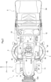
- Fig.1 shows an overall side view of a riding mower as an example of a "work vehicle".
- this riding mower on the front side of a machine body frame 10 of a traveling machine body 1, there are provided a pair of left and right steerable front wheels 11, 11 and on the rear side, there are provided a pair of left and right drivable rear wheels 12, 12, thus enabling a self-propelled traveling.
- a rear discharge type mower device 4 Under the machine body frame 10 and between the front wheels 11 and the rear wheels 12 in the front/rear direction, there is mounted a rear discharge type mower device 4 under a liftable suspended state. And, on the rear side of this traveling machine body 1, there is provided a grass collecting device 5 for collecting cut grass pieces mowed by the mower device 4.
- an engine section 2 is provided at a front portion thereof and a riding driving section 3 is provided rearwardly of the engine section 2.
- an engine 20 as being accommodated in a hood 21, is mounted on the machine body frame 10. Power taken off from the rear side of the engine 20 is inputted via a main transmission shaft 22 to a transmission case 23 disposed at a rear position. Power speed-changed in the transmission case 23 is outputted to the rear wheels 12, etc.
- a maneuvering section 3A In the riding driving section 3 rearwardly of the engine section 2, a maneuvering section 3A is provided.
- This maneuvering section 3A includes a maneuvering panel 30 continuous with the rear side of the hood 21, a steering wheel 31, etc.
- a driver's seat 33 is disposed on the upper side of a step deck 32 located at the driver's foot.
- a ROPS 34 is mounted vertically.
- the ROPS 34 has a portal shape as seen in a front view and to a pair of left and right ROPS bases (not shown) provided integrally at the rear end portion of the machine body frame 10, lower end sides of pillar like leg portions 34a, 34b on the left and right opposed sides are fixedly coupled.
- the upper end sides of the left and right pillar-like leg portions 34a, 34a are connected to each other via an upper frame 34b of the portal shape.
- the upper frame 34b is provided to cover the upper side of the driver's seat 33.
- a PTO mechanism 15 constituted of a belt transmission mechanism. Via a PTO shaft 16 included in this PTO mechanism 15, the power of the engine 20 is transmitted to the mower device 4.
- a guard frame 10A acting as a protective member for the machine body front portion.
- This guard frame 10A includes a balance weight attachment portion 14 to which a plurality of balance weights can be attached.
- the hood 21 provided in the engine section 2 includes a lower hood 24 and an upper hood 25.
- the lower hood 24 is fixed to the machine body frame 10 to form a lower space inside the hood 21.
- the upper hood 25 forms an upper space inside the hood 21 upwardly of the lower hood 24.
- an opening portion 26 is formed between a rear end portion of an upper edge 24a of the lower hood 24 and a rear end portion of a lower edge 25a of the upper hood 25, an opening portion 26 is formed.
- this opening portion 26 a part of a stop operational mechanism 7 (to be described later) extending from the outside to the inside of the hood 21 is provided as being inserted through this opening portion 26.
- the engine 20 is a diesel engine and includes a fuel injection pump 27 as a fuel supplying device for supplying fuel to the inner chamber of the cylinder.
- the fuel injection pump 27 includes a stop lever 28. This stop lever 28 can be switchable in its position between an operational position P1 for allowing supply of fuel from the fuel injection pump 27 to the engine 20 and a stop position P2 for stopping operation of the engine 20 by stopping fuel supply from the fuel injection pump 27 to the engine 20.
- a stop solenoid 29 acting as an operational device operable in response to an operational command from a key switch (not show) provided in the maneuvering section 3A.
- the stop lever 28 is configured to be operable between the operational position P1 and the stop position P2 so that starting of the engine 20 and operation stopping of the engine 20 may be effected by an operation of the stop solenoid 29.
- stop lever 28 is connected also to an engine emergency stop device 6 to be described later.
- the stop lever 28 is configured to be operable between the operational position P1 and the stop position P2 in association with a manual operation by the engine emergency stop device 6.
- the mower device 4 includes a housing 40.
- the housing 40 is supported in suspension to the machine body frame 10 to be liftable up/down via a link mechanism 13 having a pair of front link 13a and rear link 13b on the left and right opposed sides respectively.
- a mower lift cylinder 43 is coupled to the upper end portion of the front link 13a. In association with expanding/contracting motion of this mower lift cylinder 43, a vertical height position of the housing 40 relative to the machine body frame 10 can be changed.
- Each rotary blade 41 is rotatable about a vertical axis.
- the respective rotary blades 41 will be driven to rotate at an equal speed with portions of their rotary paths being overlapped with each other.
- the rotational drive directions of the pair of left and right rotary blades 41 are as follows. Namely, the rotational direction of the left rotary blade 41 is clockwise as seen in the plan view. The rotational direction of the right rotary blade 41 is counterclockwise as seen in the plan view.
- the grass collecting device 5 includes a grass collecting container 50 and a lift drive mechanism 51.
- the grass collecting container 50 stores cut grass pieces.
- the lift drive mechanism 51 operates to allow a lifting operation and a cut grass discharging operation of the grass collecting container 50 relative to the traveling machine body.
- the grass collecting container 50 includes, on its front end side, a receiving opening (not shown) for receiving cut grass pieces supplied thereto via a conveying duct 42 from the mower device 4 side.
- the grass collecting container 50 includes, on the rear end side thereof, a discharge exit 50a for discharging and an opening/closing lid 50b which covers the discharge exit 50a.
- the lift drive mechanism 51 includes a lift link 52, a lift cylinder 53 (corresponding to a "hydraulic actuator") and a dump cylinder 54 (corresponding to a "hydraulic actuator”).
- the lift link 52 operably couples the grass collecting container 50 to the ROPS 34 provided on the rear side of the traveling machine body 1.
- the lift cylinder 53 lifts the lift link 52 up/down relative to the ROPS 34.
- the dump cylinder 54 is provided for changing the posture of the grass collecting container 50 relative to the lift link 52 from a state of a nearly horizontal collecting posture to a rearwardly lowered rear inclined posture to open/close the opening/closing lid 50b of the grass collecting container 50.
- the lift link 52 includes a pair of left and right upper links 52a and a pair of left and right lower links 52b.
- the front end side of each upper link 52a and the front end side of each lower link 52b are detachably coupled to an upper portion of the ROPS 34.
- the rear end side of each upper link 52a and the rear end side of each lower link 52b are coupled to a lower portion adjacent the rear end side of the grass collecting container 50.
- the upper end portion of the lift cylinder 53 constituted of a hydraulic cylinder is coupled to the lower link 52b. In association with an expanding/contacting motion of the lift cylinder 53, the lift link 52 is pivoted to carry out a lifting up/down operation of the grass collecting container 50.
- the engine emergency stop device 6 for stopping the engine 20 inside the hood 21 by a manual operation.
- This engine emergency stop device 6 is provided for stopping an operation of the engine 20 by a manual operation, separately or independently of operations of starting/stopping the engine 20 by means of the stop solenoid 29 which is operated in response to a command from the key switch (not shown) provided in the maneuvering section 3A.
- the engine emergency stop device 6 is provided at the front end portion of the step deck 32 which is outside the hood 21.
- the engine emergency stop device 6 includes a stop command operational tool 60 which is manually operable and a stop operational mechanism 7.
- the stop operational mechanism 7 is configured to communicate a stop command manually provided by the stop command operational tool 60 to the stop lever 28, independently of the stop solenoid 29 as an operational device.
- the disposing position of this stop command operational tool 60 on the step deck 32 is such a position that can be gripped by a driver located at the riding driving section 3 by extending his/her hand from the driver's seat 33 downwardly and forwardly and that also can be gripped and operated from the lateral side of the machine body by a driver who has got off the step deck 32 and stands on the ground.
- the stop operational mechanism 7, as shown in Figs. 3 through 5 includes a starting end operational portion 7S, a terminal end operational portion 7E and an intermediate connecting portion 7M.
- the starting end operational portion 7S transmits an operational force along an operational direction of the stop command operational tool 60.
- the terminal end operational portion 7E transmits the operational force of the stop command operational tool 60 along an operational direction of the stop lever 28.
- the intermediate connecting portion 7M connects the starting end operational portion 7S with the terminal end operational portion 7E.
- An interlocking arrangement is provided such that the stop lever 28 is located at the operational position P1 when the operational knob 62 is under its free state. And, when the operational knob 62 under the free state is gripped and pulled rearwards, a first rod 70 as the starting end operational portion 7S can be pulled toward the rear side. As shown in Fig. 3 and Fig. 4 , when the operational knob 62 has been pulled out to the position corresponding to the stop position P2 of the stop lever 28, fuel supply from the fuel injection pump 27 to the engine 20 is stopped, whereby the operation of the engine 20 is stopped.
- the attachment bracket 61 is used also as an attachment metal tool for vertically mounting a fender mirror 35 to the front end portion of the upper face of the step deck 32.
- the constituent members of the stop operational mechanism 7 include the first rod 70, a second rod 71 and a pivot link member 72.
- One end side (rear end side) of the first rod 70 is connected to the operational knob 62.
- the other end side (front end side) of the first rod 70 is connected to the lower end portion of the pivot link member 72.
- One end side (rear end side) of the second rod 71 is connected to the stop lever 28 and the other end side (front end side) of the second rod 71 is connected to the upper end portion of the pivot link member 72.
- the pivot link member 72 connects the first rod 70 with the second rod 71.
- a longitudinally intermediate portion of the first rod 70 is bent in the form of a crank and the more rear side than the bent portion in the first rod 70 is a first starting end operational portion 7s1 as the starting end operational portion 7S.
- the more front side than the bent portion in the first rod 70 is a second starting end operational portion 7s2 as the starting end operational portion 7S.
- a first intermediate connecting portion 7m1 as the intermediate connecting portion 7M along the left/right direction.
- This first intermediate connecting portion 7m1 is present at the position that can extend through the opening portion 26 of the hood 21. Therefore, the first starting end operational portion 7s1 will be located outside the hood 21 and the second starting end operational portion 7s2 is located inside the hood 21.
- the stop lever 28 is constituted of a bell-crank like member attached to be rotatable about a vertical axis y1 at the main body upper position of the engine 20 (see Fig. 4 and Fig. 5 ).
- This stop lever 28 includes extension portions 28a, 28b.
- the extension portions 28a, 28b extend in two directions along the horizontal direction as branching in bifurcation from the vicinity of the portion where the vertical axis y1 is present. And, from an end portion of one extension portion 28a of these extension portions 28a, 28b, there is formed a rising protrusion piece portion 28c. To the upper end of this protrusion piece portion 28c, the stop solenoid 29 is connected. And, to an end portion of the other extension portion 28b of the extension portions 28a, 28b, a rear end portion of the second rod 71 is connected.
- the pivot link member 72 as the second intermediate connecting portion 7m2 in the intermediate connecting portion 7M, the lower end portion thereof is coupled to the front end portion of the first rod 70.
- the upper end portion of the pivot link member 72 is coupled to the front end portion of the second rod 71.
- a vertically intermediate portion of the pivot link member 72 is supported by a horizontal support shaft 73.
- This horizontal support shaft 73 protrudes to the left laterally outer side from an attachment member 74 attached to the lateral portion of the main body of the engine 20.
- the pivot link member 72 is supported to be pivotable to the front/rear sides about a horizontal axis x1 of this horizontal support shaft 73.
- the first intermediate connecting portion 7m1 couples the first starting end operational portion 7s1 with the second starting end operational portion 7s2 so as to compensate for an error in the position in the left/right direction between the first starting end operational portion 7s1 and the second starting end operational portion 7s2.
- the first starting end operational portion 7s1 transmits the operational force along the operational direction of the operational knob 62 located outside the hood 21.
- the second starting end operational portion 7s2 moves, at the position inside the hood 21, along the operational direction of the operational knob 62.
- the second intermediate connecting portion 7m2 compensates for an error in the operational positions in the left/right direction and in the vertical direction, between the first starting end operational portion 7s1 as the starting end operational portion 7S for transmitting the operational force along the operational direction of the operational knob 62 and the second rod 71 as the terminal end operational portion 7E and compensates also for an error in the operational directions of the first rod 70 and the second rod 71 whose moving directions are in reverse.
- the intermediate connecting portion 7M includes the two kinds consisting of the first intermediate connecting portion 7m1 and the second intermediate connecting portion 7m2, the intermediate connecting portion 7M may alternatively be constituted of using the first intermediate connecting portion 7m1 alone.
- the pivot link member 72 as the second intermediate connecting portion 7m2 and the second rod 71 as the terminal end operational portion 7E will be removed.
- the front end portion of the second starting end operational portion 7s2 will be coupled to the lower end portion of the stop lever 28 and the stop operational mechanism 7 will be constituted of only the first rod 70 having the first intermediate connecting portion 7m1 between the first starting end operational portion 7s1 and the second starting end operational portion 7s2.
- the first starting end operational portion 7s1 of the first rod 70 will be used as the starting end operational portion 7S along the operational direction of the operational knob 62 and the second starting end operational portion 7s2 of the first rod 70 coupled to the stop lever 28 will be used as the terminal end operational portion 7E.
- the intermediate connecting portion 7M having only the first intermediate connecting portion 7m1 will compensate for a positional error in the left/right direction between the starting end operational portion 7S and the terminal end operational portion 7E.
- the intermediate connecting portion 7M may employ a plurality of first intermediate connecting portions 7m1 alone or a plurality of second intermediate connecting portions 7m2 alone or may employ three or more of the first intermediate connecting portions 7m1 and the second intermediate connecting portions 7m2 in any appropriate combination (namely, a combination of different kinds).
- the stop operational mechanism 7 may be constituted of an arrangement of using a part of such intermediate connecting portion 7M alone.
- the intermediate connecting portion 7M include one detachable from the starting end operational portion 7S or the terminal end operational portion 7E and one non-detachable from the starting end operational portion 7S.
- the intermediate connecting portion 7M may be constituted of only one detachable from the starting end operational portion 7S or the terminal end operational portion 7E or of only one non-detachable from the starting end operational portion 7S or the terminal end operational portion 7E.
- the attachment target portion may be provided at such a portion as the maneuvering panel 30 portion other than the step deck 32.
- a work vehicle to which the inventive emergency stop device of a work vehicle may be applied is not limited to a riding mower disclosed in the embodiment, but may be a moving farming machine such as a tractor, a combine, etc. or various kinds of work vehicle such as a transporter vehicle.
Landscapes
- Engineering & Computer Science (AREA)
- Chemical & Material Sciences (AREA)
- Combustion & Propulsion (AREA)
- Mechanical Engineering (AREA)
- General Engineering & Computer Science (AREA)
- Life Sciences & Earth Sciences (AREA)
- Environmental Sciences (AREA)
- Control Of Throttle Valves Provided In The Intake System Or In The Exhaust System (AREA)
- Superstructure Of Vehicle (AREA)
- High-Pressure Fuel Injection Pump Control (AREA)
- Output Control And Ontrol Of Special Type Engine (AREA)
Description
- The present invention relates to an engine emergency stop device of a work vehicle configured such that an emergency stop of an engine is possible via a stop operational mechanism configured to communicate a stop command provided by a stop command operational tool provided separately of a key switch and outside a hood to an engine stop lever separately of the key switch.
- As an engine emergency stop device of a work vehicle configured such that an emergency stop of the engine is possible by an operation of a stop command operational tool provided separately of a key switch and outside a hood, conventionally, there is a technique as follows.
- Namely, separately of an electric stop operational system using a stopping motor operable based on an operation on a key switch, a manual stop operational system is employed to manually operate an engine stop tool to stop fuel supply from a fuel injection pump, thus stopping the engine (see Patent Document 1 for example).
- Patent Document 1:
Japanese Utility Model Application Publication No. Hei. 2-110238 - The documents
JP S54 173141 U GB 2 084 660 A - In the engine emergency stop device of the work vehicle disclosed in Patent Document 1, as described above, there is provided an engine stop tool for controlling feeding/discharging of fuel to/from the fuel injection pump. And, this engine stop tool is operably interlocked with the electric stop operational system using the stopping motor and a manual stop operational system using a stop operational mechanism so that it is possible to pivotally operate a stop lever to control feeding/discharging of fuel not only by the key switch, but also by a manual stop command operational tool provided separately of the key switch.
- Therefore, for instance, even when stop is not possible by the key switch due to shortage in the voltage of a battery, the engine can yet be stopped by a manual operation. In this respect, the arrangement is advantageous.
- On the other hand, in case there occurs a significant change inside the hood in the disposing position of the fuel injection pump or the engine stop tool due to a specification (design) change made in the engine, the stop operational mechanism used prior to such design change becomes no longer usable as it is, but there arises a need to re-design the stop operational mechanism in accordance with the change occurring in the position of the engine stop tool.
- The present invention is intended to utilize an engine emergency stop device having a stop operational mechanism commonly usable for various machine types differing in the disposing position or operational direction of a stop lever for engine stop which is disposed inside a hood.
- One aspect of the present invention is defined in claim 1. An engine emergency stop device of a work vehicle comprises:
- a stop lever provided inside a hood and switchable between an operational position for allowing an operation of the engine and an operation stopping position for stopping an operation of the engine;
- an operational device configured to automatically operate the stop lever to the operation stopping position in response to an operation of a key switch to an OFF position;
- a stop command operational tool provided separately of the key switch and outside the hood; and
- a stop operational mechanism configured to communicate a stop command by the stop command operational tool to the stop lever separately of the operational device;
- wherein the stop operational mechanism includes a starting end operational portion for transmitting an operational force along an operational direction of the stop command operational tool, a terminal end operational portion for transmitting the operational force of the stop command operational tool along an operational direction of the stop lever, and an intermediate connecting portion connecting the starting end operational portion with the terminal end operational portion; and
- wherein the intermediate connecting portion is configured to compensate for an error between the starting end operational portion and the terminal end operational portion in the operational direction or the operational position to operate the terminal end operational portion toward the engine stopping side in association with an operation of the starting end operational portion toward the engine stopping side.
- With the present invention described above, separately of the key switch, a stop command operational tool provided outside the hood is connected to the stop lever via the stop operational mechanism. This stop operational mechanism includes a starting end operational portion for transmitting an operational force along an operational direction of the stop command operational tool, a terminal end operational portion for transmitting the operational force of the stop command operational tool along an operational direction of the stop lever, and an intermediate connecting portion connecting the starting end operational portion with the terminal end operational portion. Therefore, even when an engine stop is not possible by the key switch, the engine stop is made still possible by a manual operation by manually operating the stop command operational tool.
- And, the intermediate connecting portion compensates for an error between the starting end operational portion and the terminal end operational portion in the operational direction or the operational position to operate the terminal end operational portion toward the engine stopping side in association with an operation of the starting end operational portion toward the engine stopping side. Therefore, with appropriate adjustment at the intermediate connecting portion of an amount of error present in the operational direction or the operational position, the stop lever at the corresponding position can be manually operated toward the engine stopping side.
- In the above-described arrangement, preferably, the intermediate connecting portion is provided at a plurality of portions in the stop operational mechanism.
- With the above-described inventive arrangement, as the intermediate connecting portion is provided at a plurality of portions, there is obtained greater degree of freedom in setting the operational directions or the disposing positions of the starting end operational portion and the terminal end operational portion. With this, with favorable and good correspondence with the stop lever at a plurality of portions which may be provided at different disposing positions or operational directions, the stop lever can be manually operated toward the engine stopping side.
- In the above-described arrangement, preferably, the stop operational mechanism is configured such that a part of the intermediate connecting portion is detachable.
- With the above-described inventive arrangement, attachment is possible also with a part of the intermediate connecting portion being omitted. With this, use is made possible with weight-reduced arrangement with a non-used part of the stop operational mechanism being eliminated.
- In the above-described arrangement:
- the hood includes a lower hood fixed to a machine body frame and forming a lower space inside the hood and an upper hood forming an upper space inside the hood and upwardly of the lower hood; and
- between an upper edge of the lower hood and a lower edge of the upper hood, there is formed an opening portion at which a portion of the stop operational mechanism extending from the outer side to the inner side of the hood is located to allow movement of the starting end operational portion in its operational direction.
- With the above-described inventive arrangement, the engine emergency stop device can be disposed with inserting a part of the stop operational mechanism extending from the outer side to the inner side of the hood at the opening portion formed between the upper edge of the lower hood and the lower edge of the upper hood.
- With the above, it is possible to dispose the engine emergency stop device at a position not to interfere with an opening/closing operation of the hood. And, at the time of inspection or an assembly/disassembly operation of the engine emergency stop device, such operation can be carried out easily only by opening/closing the hood.
- In the above-described arrangement, preferably:
- a step deck is provided on the machine body frame;
- at a front end portion on the step deck, an operational knob as the stop command operational tool is supported; and
- the stop lever is operated toward the engine stopping side by an operation of the operational knob in a pulling direction.
- With the above-described inventive arrangement, an operational knob as the stop command operational tool is provided at the front end portion on the step deck. Therefore, the operational knob can be disposed near the hood at a position hardly interfering with the driver who is located on the step deck. Further, the operational knob is disposed at a position that can be relatively easily operated by the driver who has gotten off and located on the ground surface.
- And, with the above-described inventive arrangement, the stop lever is operated toward the engine stopping side not by a pushing operation, but by a pulling operation of the operational knob. Even if a foot of the driver located on the step deck comes into contact with the operational knob, this foot contact is a pushing operation of the operational knob, not its pulling operation. Therefore, it is readily possible to avoid inadvertent engine stop operation.
- In the above-described arrangement, preferably:
- a fender mirror is attached to the front end portion of the step deck; and
- the operational knob is supported to an attachment metal tool of the fender mirror.
- With the above-described inventive arrangement, an attachment metal tool for the fender mirror can be used as a support metal tool for the operational knob. With this, even further simplification of the arrangement is made possible.
-
-
Fig. 1 is a side view showing an engine section of a riding mower, -
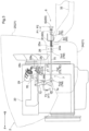
Fig. 2 is a plan view showing the engine section of the riding mower, -
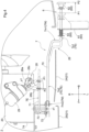
Fig. 3 is a side view showing an engine emergency stop device, -
Fig. 4 is a plan view showing the engine emergency stop device, -
Fig. 5 is an exploded perspective view showing the engine emergency stop device, and -
Fig. 6 is a side view showing a further mode of use of the engine emergency stop device. - Next, an embodiment of the present invention will be explained with reference to the accompanying drawings.
- Incidentally, the front/rear direction and the left/right direction in the explanation of the instant embodiment are defined as follows, unless explicitly indicated otherwise. Namely, the advancing direction on the forward traveling side during work travel of the engine emergency stop device of the work vehicle to which the present invention is applied (see arrow F in
Fig. 1 ) will be defined as "front", the advancing direction to the reverse traveling side (see arrow B inFig. 1 ) will be defined as "rear", the direction corresponding to the right side relative to the forwardly oriented posture in the front/rear direction will be defined as "right" and the direction corresponding to the left side similarly will be defined as "left", respectively. -
Fig.1 shows an overall side view of a riding mower as an example of a "work vehicle". In this riding mower, on the front side of amachine body frame 10 of a traveling machine body 1, there are provided a pair of left and right steerablefront wheels rear wheels - Under the
machine body frame 10 and between thefront wheels 11 and therear wheels 12 in the front/rear direction, there is mounted a rear dischargetype mower device 4 under a liftable suspended state. And, on the rear side of this traveling machine body 1, there is provided agrass collecting device 5 for collecting cut grass pieces mowed by themower device 4. - As shown in
Fig. 1 andFig. 2 , on themachine body frame 10 of the traveling machine body 1, anengine section 2 is provided at a front portion thereof and ariding driving section 3 is provided rearwardly of theengine section 2. - In the
engine section 2, anengine 20 as being accommodated in ahood 21, is mounted on themachine body frame 10. Power taken off from the rear side of theengine 20 is inputted via amain transmission shaft 22 to atransmission case 23 disposed at a rear position. Power speed-changed in thetransmission case 23 is outputted to therear wheels 12, etc. - In the
riding driving section 3 rearwardly of theengine section 2, amaneuvering section 3A is provided. Thismaneuvering section 3A includes amaneuvering panel 30 continuous with the rear side of thehood 21, asteering wheel 31, etc. And, on the rear side of themaneuvering section 3A, a driver'sseat 33 is disposed on the upper side of astep deck 32 located at the driver's foot. At a rear portion of this driver'sseat 33, aROPS 34 is mounted vertically. - The
ROPS 34 has a portal shape as seen in a front view and to a pair of left and right ROPS bases (not shown) provided integrally at the rear end portion of themachine body frame 10, lower end sides of pillar likeleg portions like leg portions upper frame 34b of the portal shape. Theupper frame 34b is provided to cover the upper side of the driver'sseat 33. - From the front side of the
engine 20, power for utility work can be taken off. Namely, on the front side of theengine 20, there is provided aPTO mechanism 15 constituted of a belt transmission mechanism. Via a PTO shaft 16 included in thisPTO mechanism 15, the power of theengine 20 is transmitted to themower device 4. - At a front portion of the
machine body frame 10, there is provided aguard frame 10A acting as a protective member for the machine body front portion. - This
guard frame 10A includes a balanceweight attachment portion 14 to which a plurality of balance weights can be attached. - The
hood 21 provided in theengine section 2 includes alower hood 24 and anupper hood 25. Thelower hood 24 is fixed to themachine body frame 10 to form a lower space inside thehood 21. Theupper hood 25 forms an upper space inside thehood 21 upwardly of thelower hood 24. Between a rear end portion of anupper edge 24a of thelower hood 24 and a rear end portion of alower edge 25a of theupper hood 25, an openingportion 26 is formed. - In this
opening portion 26, a part of a stop operational mechanism 7 (to be described later) extending from the outside to the inside of thehood 21 is provided as being inserted through this openingportion 26. - The
engine 20 is a diesel engine and includes afuel injection pump 27 as a fuel supplying device for supplying fuel to the inner chamber of the cylinder. Thefuel injection pump 27 includes astop lever 28. Thisstop lever 28 can be switchable in its position between an operational position P1 for allowing supply of fuel from thefuel injection pump 27 to theengine 20 and a stop position P2 for stopping operation of theengine 20 by stopping fuel supply from thefuel injection pump 27 to theengine 20. - To the
stop lever 28, there is connected astop solenoid 29 acting as an operational device operable in response to an operational command from a key switch (not show) provided in themaneuvering section 3A. Thestop lever 28 is configured to be operable between the operational position P1 and the stop position P2 so that starting of theengine 20 and operation stopping of theengine 20 may be effected by an operation of thestop solenoid 29. - Further, the
stop lever 28 is connected also to an engineemergency stop device 6 to be described later. Thestop lever 28 is configured to be operable between the operational position P1 and the stop position P2 in association with a manual operation by the engineemergency stop device 6. - The
mower device 4 includes ahousing 40. Thehousing 40 is supported in suspension to themachine body frame 10 to be liftable up/down via alink mechanism 13 having a pair offront link 13a andrear link 13b on the left and right opposed sides respectively. - Of the
link mechanism 13, to the upper end portion of thefront link 13a, amower lift cylinder 43 is coupled. In association with expanding/contracting motion of thismower lift cylinder 43, a vertical height position of thehousing 40 relative to themachine body frame 10 can be changed. - Inside the
housing 40, there are disposed a pair of left andright rotary blades rotary blade 41 is rotatable about a vertical axis. Therespective rotary blades 41 will be driven to rotate at an equal speed with portions of their rotary paths being overlapped with each other. The rotational drive directions of the pair of left andright rotary blades 41 are as follows. Namely, the rotational direction of theleft rotary blade 41 is clockwise as seen in the plan view. The rotational direction of theright rotary blade 41 is counterclockwise as seen in the plan view. As therotary blades housing 40. - As shown in
Fig. 1 andFig. 2 , thegrass collecting device 5 includes agrass collecting container 50 and alift drive mechanism 51. Thegrass collecting container 50 stores cut grass pieces. Thelift drive mechanism 51 operates to allow a lifting operation and a cut grass discharging operation of thegrass collecting container 50 relative to the traveling machine body. - The
grass collecting container 50 includes, on its front end side, a receiving opening (not shown) for receiving cut grass pieces supplied thereto via a conveyingduct 42 from themower device 4 side. Thegrass collecting container 50 includes, on the rear end side thereof, adischarge exit 50a for discharging and an opening/closing lid 50b which covers thedischarge exit 50a. - The
lift drive mechanism 51 includes alift link 52, a lift cylinder 53 (corresponding to a "hydraulic actuator") and a dump cylinder 54 (corresponding to a "hydraulic actuator"). The lift link 52 operably couples thegrass collecting container 50 to theROPS 34 provided on the rear side of the traveling machine body 1. Thelift cylinder 53 lifts thelift link 52 up/down relative to theROPS 34. Thedump cylinder 54 is provided for changing the posture of thegrass collecting container 50 relative to the lift link 52 from a state of a nearly horizontal collecting posture to a rearwardly lowered rear inclined posture to open/close the opening/closing lid 50b of thegrass collecting container 50. - The
lift link 52 includes a pair of left and rightupper links 52a and a pair of left and rightlower links 52b. The front end side of eachupper link 52a and the front end side of eachlower link 52b are detachably coupled to an upper portion of theROPS 34. The rear end side of eachupper link 52a and the rear end side of eachlower link 52b are coupled to a lower portion adjacent the rear end side of thegrass collecting container 50. And, the upper end portion of thelift cylinder 53 constituted of a hydraulic cylinder is coupled to thelower link 52b. In association with an expanding/contacting motion of thelift cylinder 53, thelift link 52 is pivoted to carry out a lifting up/down operation of thegrass collecting container 50. - As shown in
Figs. 1 through 5 , there is provided the engineemergency stop device 6 for stopping theengine 20 inside thehood 21 by a manual operation. This engineemergency stop device 6 is provided for stopping an operation of theengine 20 by a manual operation, separately or independently of operations of starting/stopping theengine 20 by means of thestop solenoid 29 which is operated in response to a command from the key switch (not shown) provided in themaneuvering section 3A. - The engine
emergency stop device 6 is provided at the front end portion of thestep deck 32 which is outside thehood 21. The engineemergency stop device 6 includes a stop commandoperational tool 60 which is manually operable and a stopoperational mechanism 7. The stopoperational mechanism 7 is configured to communicate a stop command manually provided by the stop commandoperational tool 60 to thestop lever 28, independently of thestop solenoid 29 as an operational device. - The disposing position of this stop command
operational tool 60 on thestep deck 32 is such a position that can be gripped by a driver located at theriding driving section 3 by extending his/her hand from the driver'sseat 33 downwardly and forwardly and that also can be gripped and operated from the lateral side of the machine body by a driver who has got off thestep deck 32 and stands on the ground. - The stop
operational mechanism 7, as shown inFigs. 3 through 5 , includes a starting endoperational portion 7S, a terminal endoperational portion 7E and an intermediate connectingportion 7M. The starting endoperational portion 7S transmits an operational force along an operational direction of the stop commandoperational tool 60. The terminal endoperational portion 7E transmits the operational force of the stop commandoperational tool 60 along an operational direction of thestop lever 28. The intermediate connectingportion 7M connects the starting endoperational portion 7S with the terminal endoperational portion 7E. - As shown in
Figs. 3 through 5 , the stop commandoperational tool 60 includes an attachment bracket 61 (corresponding to an "attachment metal tool") fixed to an upper face front end portion of thestep deck 32, anoperational knob 62 and areturn urging spring 63. - An interlocking arrangement is provided such that the
stop lever 28 is located at the operational position P1 when theoperational knob 62 is under its free state. And, when theoperational knob 62 under the free state is gripped and pulled rearwards, afirst rod 70 as the starting endoperational portion 7S can be pulled toward the rear side. As shown inFig. 3 andFig. 4 , when theoperational knob 62 has been pulled out to the position corresponding to the stop position P2 of thestop lever 28, fuel supply from thefuel injection pump 27 to theengine 20 is stopped, whereby the operation of theengine 20 is stopped. - The
attachment bracket 61 is used also as an attachment metal tool for vertically mounting afender mirror 35 to the front end portion of the upper face of thestep deck 32. - The constituent members of the stop
operational mechanism 7 include thefirst rod 70, asecond rod 71 and apivot link member 72. One end side (rear end side) of thefirst rod 70 is connected to theoperational knob 62. The other end side (front end side) of thefirst rod 70 is connected to the lower end portion of thepivot link member 72. One end side (rear end side) of thesecond rod 71 is connected to thestop lever 28 and the other end side (front end side) of thesecond rod 71 is connected to the upper end portion of thepivot link member 72. Thepivot link member 72 connects thefirst rod 70 with thesecond rod 71. - As shown in
Fig. 4 , a longitudinally intermediate portion of thefirst rod 70 is bent in the form of a crank and the more rear side than the bent portion in thefirst rod 70 is a first starting end operational portion 7s1 as the starting endoperational portion 7S. The more front side than the bent portion in thefirst rod 70 is a second starting end operational portion 7s2 as the starting endoperational portion 7S. And, in the bent portion bridging between the first starting end operational portion 7s1 and the second starting end operational portion 7s2, there is provided a first intermediate connecting portion 7m1 as the intermediate connectingportion 7M along the left/right direction. This first intermediate connecting portion 7m1 is present at the position that can extend through the openingportion 26 of thehood 21. Therefore, the first starting end operational portion 7s1 will be located outside thehood 21 and the second starting end operational portion 7s2 is located inside thehood 21. - As shown in
Fig. 4 , the front end portion of thesecond rod 71 as the terminal endoperational portion 7E is connected to the upper end portion of thepivot link member 72. The rear end portion of thesecond rod 71 is connected to thestop lever 28. - The
stop lever 28 is constituted of a bell-crank like member attached to be rotatable about a vertical axis y1 at the main body upper position of the engine 20 (seeFig. 4 andFig. 5 ). - This
stop lever 28 includesextension portions extension portions extension portion 28a of theseextension portions protrusion piece portion 28c. To the upper end of thisprotrusion piece portion 28c, thestop solenoid 29 is connected. And, to an end portion of theother extension portion 28b of theextension portions second rod 71 is connected. - In the
pivot link member 72 as the second intermediate connecting portion 7m2 in the intermediate connectingportion 7M, the lower end portion thereof is coupled to the front end portion of thefirst rod 70. The upper end portion of thepivot link member 72 is coupled to the front end portion of thesecond rod 71. And, a vertically intermediate portion of thepivot link member 72 is supported by ahorizontal support shaft 73. Thishorizontal support shaft 73 protrudes to the left laterally outer side from anattachment member 74 attached to the lateral portion of the main body of theengine 20. Thepivot link member 72 is supported to be pivotable to the front/rear sides about a horizontal axis x1 of thishorizontal support shaft 73. - Of the intermediate connecting
portion 7M, the first intermediate connecting portion 7m1 couples the first starting end operational portion 7s1 with the second starting end operational portion 7s2 so as to compensate for an error in the position in the left/right direction between the first starting end operational portion 7s1 and the second starting end operational portion 7s2. The first starting end operational portion 7s1 transmits the operational force along the operational direction of theoperational knob 62 located outside thehood 21. The second starting end operational portion 7s2 moves, at the position inside thehood 21, along the operational direction of theoperational knob 62. - Of the intermediate connecting
portion 7M, the second intermediate connecting portion 7m2 compensates for an error in the operational positions in the left/right direction and in the vertical direction, between the first starting end operational portion 7s1 as the starting endoperational portion 7S for transmitting the operational force along the operational direction of theoperational knob 62 and thesecond rod 71 as the terminal endoperational portion 7E and compensates also for an error in the operational directions of thefirst rod 70 and thesecond rod 71 whose moving directions are in reverse. - Unlike the above-described arrangement in which as the stop
operational mechanism 7 of the engineemergency stop device 6, the intermediate connectingportion 7M includes the two kinds consisting of the first intermediate connecting portion 7m1 and the second intermediate connecting portion 7m2, the intermediate connectingportion 7M may alternatively be constituted of using the first intermediate connecting portion 7m1 alone. - Namely, as shown in
Fig. 6 , in case the engineemergency stop device 6 is applied to anengine 20 having thestop lever 28 being provided at a lateral portion of the engine main body, an arrangement will be made as follows. - Firstly, the
pivot link member 72 as the second intermediate connecting portion 7m2 and thesecond rod 71 as the terminal endoperational portion 7E will be removed. Then, the front end portion of the second starting end operational portion 7s2 will be coupled to the lower end portion of thestop lever 28 and the stopoperational mechanism 7 will be constituted of only thefirst rod 70 having the first intermediate connecting portion 7m1 between the first starting end operational portion 7s1 and the second starting end operational portion 7s2. - In this case, the first starting end operational portion 7s1 of the
first rod 70 will be used as the starting endoperational portion 7S along the operational direction of theoperational knob 62 and the second starting end operational portion 7s2 of thefirst rod 70 coupled to thestop lever 28 will be used as the terminal endoperational portion 7E. And, the intermediate connectingportion 7M having only the first intermediate connecting portion 7m1 will compensate for a positional error in the left/right direction between the starting endoperational portion 7S and the terminal endoperational portion 7E. - In the foregoing example, which is not part of the invention, there was disclosed an exemplary arrangement in which as the intermediate connecting
portion 7M, two kinds of intermediate connectingportions 7M consisting of the first intermediate connecting portion 7m1 and the second intermediate connecting portion 7m2 are employed in combination. - For instance, the intermediate connecting
portion 7M may employ a plurality of first intermediate connecting portions 7m1 alone or a plurality of second intermediate connecting portions 7m2 alone or may employ three or more of the first intermediate connecting portions 7m1 and the second intermediate connecting portions 7m2 in any appropriate combination (namely, a combination of different kinds). - Even in the case of employing such combination arrangement of a same kind or different kinds as the intermediate connecting
portion 7M as described above, the stopoperational mechanism 7 may be constituted of an arrangement of using a part of such intermediate connectingportion 7M alone. - The rest of the arrangement may be same as that of the foregoing embodiment.
- In the foregoing example, which is not part of the invention, there was disclosed an exemplary arrangement in which the intermediate connecting
portion 7M include one detachable from the starting endoperational portion 7S or the terminal endoperational portion 7E and one non-detachable from the starting endoperational portion 7S. - For instance, the intermediate connecting
portion 7M may be constituted of only one detachable from the starting endoperational portion 7S or the terminal endoperational portion 7E or of only one non-detachable from the starting endoperational portion 7S or the terminal endoperational portion 7E. - However, in the case of constituting the intermediate connecting
portion 7M of only the non-detachable one, it is necessary to configure an engine employed to allow operation of thestop lever 28 without any trouble even in the presence of un-used intermediate connectingportion 7M. - In the foregoing example, which is not part of the invention, there was disclosed an exemplary arrangement in which as the stop command
operational tool 60, there is provided theoperational knob 62 which can be pulled and thisoperational knob 62 is supported to theattachment bracket 61 fixed to the upper face front end portion of thestep deck 32. - For instance, the attachment target portion may be provided at such a portion as the
maneuvering panel 30 portion other than thestep deck 32. - Further, instead of the
operational knob 62, a pivotally operable operational lever or the like may be employed. - The rest of the arrangement may be same as that of the foregoing embodiment.
- A work vehicle to which the inventive emergency stop device of a work vehicle may be applied is not limited to a riding mower disclosed in the embodiment, but may be a moving farming machine such as a tractor, a combine, etc. or various kinds of work vehicle such as a transporter vehicle.
Claims (4)
- An engine emergency stop device (6) of a work vehicle comprising:a stop lever (28) provided inside a hood (21) and switchable between an operational position for allowing an operation of the engine (20) and an operation stopping position for stopping an operation of the engine (20);an operational device (29) configured to automatically operate the stop lever (28) to the operation stopping position in response to an operation of a key switch to an OFF position;a stop command operational tool (60) provided separately of the key switch and outside the hood (21); anda stop operational mechanism (7) configured to communicate a stop command by the stop command operational tool (60) to the stop lever (28) separately of the operational device (29);wherein the stop operational mechanism (7) includes a starting end operational portion (7S) for transmitting an operational force along an operational direction of the stop command operational tool (60), a terminal end operational portion (7E) for transmitting the operational force of the stop command operational tool (60) along an operational direction of the stop lever (28) and an intermediate connecting portion (7M) connecting the starting end operational portion (7S) with the terminal end operational portion (7E); andwherein the intermediate connecting portion (7M) is configured to compensate for a gap between the starting end operational portion (7S) and the terminal end operational portion (7E) in the operational direction or the operational position to operate the terminal end operational portion (7E) toward the engine stopping side in association with an operation of the starting end operational portion (7S) toward the engine stopping side;characterised in that the stop operational mechanism (7) includes a first rod (70) as the starting end operational portion (7S), a second rod (71) as the terminal end portion (7E) and a pivot link member (72) connecting the first rod (70) with the second rod (71);wherein one end portion of the first rod (70) is connected to an operational knob (62) of the stop command operational tool (60); andwherein one end portion of the second rod (71) is connected to the stop lever (28); andwherein the first rod (70) being bent in the form of a crank; andwherein the intermediate connecting portion (7M) comprises a first intermediate connecting portion (7m1) and a second intermediate connecting portion (7m2);wherein the first intermediate connecting portion (7m1) is provided in the bent portion bridging between a first starting end operational portion (7s1) and a second starting end operational portion (7s2) of the first rod (70); andwherein the pivot link member (72) is forming the second intermediate connecting portion (7m2).
- The engine emergency stop device (6) of a work vehicle of claim 1, wherein:the hood (21) includes a lower hood (24) fixed to a machine body frame (10) and forming a lower space inside the hood (21) and an upper hood (25) forming an upper space inside the hood (21) and upwardly of the lower hood (24); andbetween an upper edge (24a) of the lower hood (24) and a lower edge (25a) of the upper hood (25), there is formed an opening portion (26) at which a portion of the stop operational mechanism (7) extending from the outer side to the inner side of the hood (21) is located to allow movement of the starting end operational portion (7S) in its operational direction.
- The engine emergency stop device (6) of a work vehicle of claim 2, wherein:a step deck (32) is provided on the machine body frame (10);at a front end portion on the step deck (32), the operational knob (62) as the stop command operational tool (60) is supported; andthe stop lever (28) is operable toward the engine stopping side by an operation of the operational knob (62) in a pulling direction.
- The engine emergency stop device (6) of a work vehicle of claim 3, wherein:a fender mirror (35) is attached to the front end portion of the step deck (32); andthe operational knob (62) is supported to an attachment metal tool (61) of the fender mirror (35).
Applications Claiming Priority (1)
| Application Number | Priority Date | Filing Date | Title |
|---|---|---|---|
| JP2020084502A JP7419158B2 (en) | 2020-05-13 | 2020-05-13 | Engine emergency stop device for work vehicles |
Publications (2)
| Publication Number | Publication Date |
|---|---|
| EP3910183A1 EP3910183A1 (en) | 2021-11-17 |
| EP3910183B1 true EP3910183B1 (en) | 2025-06-25 |
Family
ID=73726704
Family Applications (1)
| Application Number | Title | Priority Date | Filing Date |
|---|---|---|---|
| EP20211964.0A Active EP3910183B1 (en) | 2020-05-13 | 2020-12-04 | Engine emergency stop device of a work vehicle |
Country Status (2)
| Country | Link |
|---|---|
| EP (1) | EP3910183B1 (en) |
| JP (1) | JP7419158B2 (en) |
Families Citing this family (1)
| Publication number | Priority date | Publication date | Assignee | Title |
|---|---|---|---|---|
| CN114451151B (en) * | 2021-12-27 | 2023-06-16 | 南京苏美达智能技术有限公司 | Emergency stop control system and control method for hybrid mower |
Citations (1)
| Publication number | Priority date | Publication date | Assignee | Title |
|---|---|---|---|---|
| EP3061955B1 (en) * | 2015-02-27 | 2019-05-15 | Kohler Co. | Equipment incorporating safety system for engine shutdown |
Family Cites Families (13)
| Publication number | Priority date | Publication date | Assignee | Title |
|---|---|---|---|---|
| JPS5012536B1 (en) * | 1970-11-16 | 1975-05-13 | ||
| JPS5834275Y2 (en) * | 1978-05-26 | 1983-08-01 | 株式会社クボタ | Diesel engine engine stop device |
| JPS55123644U (en) * | 1979-02-23 | 1980-09-02 | ||
| WO1982001219A1 (en) * | 1980-10-01 | 1982-04-15 | D Karraker | Auxiliary engine stoppage apparatus |
| US4331114A (en) * | 1980-10-01 | 1982-05-25 | Caterpillar Tractor Co. | Auxiliary engine stoppage apparatus |
| JPS57143141A (en) * | 1981-02-27 | 1982-09-04 | Komatsu Ltd | Device for stopping engine in its abnormality |
| JPS5882936U (en) * | 1981-11-30 | 1983-06-04 | セイレイ工業株式会社 | Tractor engine emergency stop device |
| JPH0630551Y2 (en) * | 1988-01-29 | 1994-08-17 | 株式会社クボタ | Headlamp device in vehicle |
| JP2521717Y2 (en) | 1989-02-17 | 1997-01-08 | 株式会社クボタ | Stopper for diesel engine |
| JP3352174B2 (en) * | 1993-09-30 | 2002-12-03 | 株式会社クボタ | Engine bonnet structure for riding lawn mower |
| JP2000170583A (en) * | 1998-12-09 | 2000-06-20 | Seirei Ind Co Ltd | Emergency stop circuit device for engine |
| JP2010094088A (en) | 2008-10-17 | 2010-04-30 | Iseki & Co Ltd | Combine harvester |
| US8897993B2 (en) * | 2012-01-13 | 2014-11-25 | Deere & Company | Detection system for front-mounted mid-PTO driven implements |
-
2020
- 2020-05-13 JP JP2020084502A patent/JP7419158B2/en active Active
- 2020-12-04 EP EP20211964.0A patent/EP3910183B1/en active Active
Patent Citations (1)
| Publication number | Priority date | Publication date | Assignee | Title |
|---|---|---|---|---|
| EP3061955B1 (en) * | 2015-02-27 | 2019-05-15 | Kohler Co. | Equipment incorporating safety system for engine shutdown |
Also Published As
| Publication number | Publication date |
|---|---|
| EP3910183A1 (en) | 2021-11-17 |
| JP2021179194A (en) | 2021-11-18 |
| JP7419158B2 (en) | 2024-01-22 |
Similar Documents
| Publication | Publication Date | Title |
|---|---|---|
| EP3295784B1 (en) | Mid-mount riding grass mower | |
| US7527298B2 (en) | Dust fender for riding type work vehicle | |
| EP3910183B1 (en) | Engine emergency stop device of a work vehicle | |
| EP3476643B1 (en) | Work machine | |
| US4332261A (en) | Automatic hydraulic neutralizing mechanism | |
| US6902016B2 (en) | Pivoting panel for mechanical control disengagement | |
| EP0941647B1 (en) | Four bar linkage mounting for mowers | |
| US11007963B2 (en) | Work vehicle having ROPS | |
| KR19990086995A (en) | Reinforcement frame of working car | |
| EP3504951B1 (en) | Riding grass mower | |
| EP3799713B1 (en) | Grass mowing machine | |
| JP6815280B2 (en) | Mower | |
| JP7023215B2 (en) | Mower | |
| JP7239748B2 (en) | riding lawn mower | |
| EP1541005B1 (en) | Traveling lawn mower | |
| JP7038638B2 (en) | Riding mower | |
| CN114651599A (en) | Combine harvester | |
| EP3504955B1 (en) | Grass mower | |
| JP2010051278A (en) | Riding type mowing machine | |
| JP2003276494A (en) | Riding work machine | |
| CN221553944U (en) | Smart lawn mower | |
| JP2008278803A (en) | Lawn mower | |
| JP3594464B2 (en) | Tractor | |
| JP2013184560A (en) | Steering device of working vehicle | |
| JP2008278804A (en) | Lawn mower |
Legal Events
| Date | Code | Title | Description |
|---|---|---|---|
| PUAI | Public reference made under article 153(3) epc to a published international application that has entered the european phase |
Free format text: ORIGINAL CODE: 0009012 |
|
| STAA | Information on the status of an ep patent application or granted ep patent |
Free format text: STATUS: REQUEST FOR EXAMINATION WAS MADE |
|
| 17P | Request for examination filed |
Effective date: 20201204 |
|
| AK | Designated contracting states |
Kind code of ref document: A1 Designated state(s): AL AT BE BG CH CY CZ DE DK EE ES FI FR GB GR HR HU IE IS IT LI LT LU LV MC MK MT NL NO PL PT RO RS SE SI SK SM TR |
|
| B565 | Issuance of search results under rule 164(2) epc |
Effective date: 20210527 |
|
| STAA | Information on the status of an ep patent application or granted ep patent |
Free format text: STATUS: EXAMINATION IS IN PROGRESS |
|
| 17Q | First examination report despatched |
Effective date: 20231214 |
|
| GRAP | Despatch of communication of intention to grant a patent |
Free format text: ORIGINAL CODE: EPIDOSNIGR1 |
|
| STAA | Information on the status of an ep patent application or granted ep patent |
Free format text: STATUS: GRANT OF PATENT IS INTENDED |
|
| RIC1 | Information provided on ipc code assigned before grant |
Ipc: A01D 34/64 20060101ALI20250305BHEP Ipc: A01D 34/82 20060101ALI20250305BHEP Ipc: F02D 17/04 20060101ALI20250305BHEP Ipc: F02D 11/02 20060101ALI20250305BHEP Ipc: F02D 41/22 20060101ALI20250305BHEP Ipc: F02M 63/02 20060101ALI20250305BHEP Ipc: F02D 41/04 20060101AFI20250305BHEP |
|
| INTG | Intention to grant announced |
Effective date: 20250313 |
|
| GRAS | Grant fee paid |
Free format text: ORIGINAL CODE: EPIDOSNIGR3 |
|
| GRAA | (expected) grant |
Free format text: ORIGINAL CODE: 0009210 |
|
| STAA | Information on the status of an ep patent application or granted ep patent |
Free format text: STATUS: THE PATENT HAS BEEN GRANTED |
|
| AK | Designated contracting states |
Kind code of ref document: B1 Designated state(s): AL AT BE BG CH CY CZ DE DK EE ES FI FR GB GR HR HU IE IS IT LI LT LU LV MC MK MT NL NO PL PT RO RS SE SI SK SM TR |
|
| REG | Reference to a national code |
Ref country code: GB Ref legal event code: FG4D |
|
| REG | Reference to a national code |
Ref country code: CH Ref legal event code: EP |
|
| REG | Reference to a national code |
Ref country code: CH Ref legal event code: EP |
|
| REG | Reference to a national code |
Ref country code: IE Ref legal event code: FG4D |
|
| REG | Reference to a national code |
Ref country code: DE Ref legal event code: R096 Ref document number: 602020053235 Country of ref document: DE |
|
| PG25 | Lapsed in a contracting state [announced via postgrant information from national office to epo] |
Ref country code: FI Free format text: LAPSE BECAUSE OF FAILURE TO SUBMIT A TRANSLATION OF THE DESCRIPTION OR TO PAY THE FEE WITHIN THE PRESCRIBED TIME-LIMIT Effective date: 20250625 |
|
| REG | Reference to a national code |
Ref country code: LT Ref legal event code: MG9D |
|
| PG25 | Lapsed in a contracting state [announced via postgrant information from national office to epo] |
Ref country code: GR Free format text: LAPSE BECAUSE OF FAILURE TO SUBMIT A TRANSLATION OF THE DESCRIPTION OR TO PAY THE FEE WITHIN THE PRESCRIBED TIME-LIMIT Effective date: 20250926 Ref country code: NO Free format text: LAPSE BECAUSE OF FAILURE TO SUBMIT A TRANSLATION OF THE DESCRIPTION OR TO PAY THE FEE WITHIN THE PRESCRIBED TIME-LIMIT Effective date: 20250925 |
|
| PG25 | Lapsed in a contracting state [announced via postgrant information from national office to epo] |
Ref country code: BG Free format text: LAPSE BECAUSE OF FAILURE TO SUBMIT A TRANSLATION OF THE DESCRIPTION OR TO PAY THE FEE WITHIN THE PRESCRIBED TIME-LIMIT Effective date: 20250625 |
|
| PG25 | Lapsed in a contracting state [announced via postgrant information from national office to epo] |
Ref country code: HR Free format text: LAPSE BECAUSE OF FAILURE TO SUBMIT A TRANSLATION OF THE DESCRIPTION OR TO PAY THE FEE WITHIN THE PRESCRIBED TIME-LIMIT Effective date: 20250625 |
|
| PG25 | Lapsed in a contracting state [announced via postgrant information from national office to epo] |
Ref country code: RS Free format text: LAPSE BECAUSE OF FAILURE TO SUBMIT A TRANSLATION OF THE DESCRIPTION OR TO PAY THE FEE WITHIN THE PRESCRIBED TIME-LIMIT Effective date: 20250925 |
|
| PG25 | Lapsed in a contracting state [announced via postgrant information from national office to epo] |
Ref country code: LV Free format text: LAPSE BECAUSE OF FAILURE TO SUBMIT A TRANSLATION OF THE DESCRIPTION OR TO PAY THE FEE WITHIN THE PRESCRIBED TIME-LIMIT Effective date: 20250625 |
|
| REG | Reference to a national code |
Ref country code: NL Ref legal event code: MP Effective date: 20250625 |
|
| PG25 | Lapsed in a contracting state [announced via postgrant information from national office to epo] |
Ref country code: NL Free format text: LAPSE BECAUSE OF FAILURE TO SUBMIT A TRANSLATION OF THE DESCRIPTION OR TO PAY THE FEE WITHIN THE PRESCRIBED TIME-LIMIT Effective date: 20250625 |
|
| PG25 | Lapsed in a contracting state [announced via postgrant information from national office to epo] |
Ref country code: PT Free format text: LAPSE BECAUSE OF FAILURE TO SUBMIT A TRANSLATION OF THE DESCRIPTION OR TO PAY THE FEE WITHIN THE PRESCRIBED TIME-LIMIT Effective date: 20251027 |
|
| REG | Reference to a national code |
Ref country code: AT Ref legal event code: MK05 Ref document number: 1806656 Country of ref document: AT Kind code of ref document: T Effective date: 20250625 |
|
| PG25 | Lapsed in a contracting state [announced via postgrant information from national office to epo] |
Ref country code: IS Free format text: LAPSE BECAUSE OF FAILURE TO SUBMIT A TRANSLATION OF THE DESCRIPTION OR TO PAY THE FEE WITHIN THE PRESCRIBED TIME-LIMIT Effective date: 20251025 |
|
| PG25 | Lapsed in a contracting state [announced via postgrant information from national office to epo] |
Ref country code: AT Free format text: LAPSE BECAUSE OF FAILURE TO SUBMIT A TRANSLATION OF THE DESCRIPTION OR TO PAY THE FEE WITHIN THE PRESCRIBED TIME-LIMIT Effective date: 20250625 Ref country code: SM Free format text: LAPSE BECAUSE OF FAILURE TO SUBMIT A TRANSLATION OF THE DESCRIPTION OR TO PAY THE FEE WITHIN THE PRESCRIBED TIME-LIMIT Effective date: 20250625 |
|
| PGFP | Annual fee paid to national office [announced via postgrant information from national office to epo] |
Ref country code: FR Payment date: 20251106 Year of fee payment: 6 |
|
| PG25 | Lapsed in a contracting state [announced via postgrant information from national office to epo] |
Ref country code: CZ Free format text: LAPSE BECAUSE OF FAILURE TO SUBMIT A TRANSLATION OF THE DESCRIPTION OR TO PAY THE FEE WITHIN THE PRESCRIBED TIME-LIMIT Effective date: 20250625 |
|
| PG25 | Lapsed in a contracting state [announced via postgrant information from national office to epo] |
Ref country code: PL Free format text: LAPSE BECAUSE OF FAILURE TO SUBMIT A TRANSLATION OF THE DESCRIPTION OR TO PAY THE FEE WITHIN THE PRESCRIBED TIME-LIMIT Effective date: 20250625 |
|
| PG25 | Lapsed in a contracting state [announced via postgrant information from national office to epo] |
Ref country code: EE Free format text: LAPSE BECAUSE OF FAILURE TO SUBMIT A TRANSLATION OF THE DESCRIPTION OR TO PAY THE FEE WITHIN THE PRESCRIBED TIME-LIMIT Effective date: 20250625 |
|
| PG25 | Lapsed in a contracting state [announced via postgrant information from national office to epo] |
Ref country code: SK Free format text: LAPSE BECAUSE OF FAILURE TO SUBMIT A TRANSLATION OF THE DESCRIPTION OR TO PAY THE FEE WITHIN THE PRESCRIBED TIME-LIMIT Effective date: 20250625 |
|
| PG25 | Lapsed in a contracting state [announced via postgrant information from national office to epo] |
Ref country code: ES Free format text: LAPSE BECAUSE OF FAILURE TO SUBMIT A TRANSLATION OF THE DESCRIPTION OR TO PAY THE FEE WITHIN THE PRESCRIBED TIME-LIMIT Effective date: 20250625 |
|
| PG25 | Lapsed in a contracting state [announced via postgrant information from national office to epo] |
Ref country code: RO Free format text: LAPSE BECAUSE OF FAILURE TO SUBMIT A TRANSLATION OF THE DESCRIPTION OR TO PAY THE FEE WITHIN THE PRESCRIBED TIME-LIMIT Effective date: 20250625 |
|
| PG25 | Lapsed in a contracting state [announced via postgrant information from national office to epo] |
Ref country code: DK Free format text: LAPSE BECAUSE OF FAILURE TO SUBMIT A TRANSLATION OF THE DESCRIPTION OR TO PAY THE FEE WITHIN THE PRESCRIBED TIME-LIMIT Effective date: 20250625 |
|
| PGFP | Annual fee paid to national office [announced via postgrant information from national office to epo] |
Ref country code: DE Payment date: 20251231 Year of fee payment: 6 |
|
| PG25 | Lapsed in a contracting state [announced via postgrant information from national office to epo] |
Ref country code: IT Free format text: LAPSE BECAUSE OF FAILURE TO SUBMIT A TRANSLATION OF THE DESCRIPTION OR TO PAY THE FEE WITHIN THE PRESCRIBED TIME-LIMIT Effective date: 20250625 |
|
| PLBE | No opposition filed within time limit |
Free format text: ORIGINAL CODE: 0009261 |
|
| STAA | Information on the status of an ep patent application or granted ep patent |
Free format text: STATUS: NO OPPOSITION FILED WITHIN TIME LIMIT |