EP3909821A1 - Bi-stable quick-release valve - Google Patents
Bi-stable quick-release valve Download PDFInfo
- Publication number
- EP3909821A1 EP3909821A1 EP20174402.6A EP20174402A EP3909821A1 EP 3909821 A1 EP3909821 A1 EP 3909821A1 EP 20174402 A EP20174402 A EP 20174402A EP 3909821 A1 EP3909821 A1 EP 3909821A1
- Authority
- EP
- European Patent Office
- Prior art keywords
- valve
- groove
- actuation
- actuation rod
- following member
- Prior art date
- Legal status (The legal status is an assumption and is not a legal conclusion. Google has not performed a legal analysis and makes no representation as to the accuracy of the status listed.)
- Granted
Links
Images

Classifications
-
- F—MECHANICAL ENGINEERING; LIGHTING; HEATING; WEAPONS; BLASTING
- F16—ENGINEERING ELEMENTS AND UNITS; GENERAL MEASURES FOR PRODUCING AND MAINTAINING EFFECTIVE FUNCTIONING OF MACHINES OR INSTALLATIONS; THERMAL INSULATION IN GENERAL
- F16K—VALVES; TAPS; COCKS; ACTUATING-FLOATS; DEVICES FOR VENTING OR AERATING
- F16K1/00—Lift valves or globe valves, i.e. cut-off apparatus with closure members having at least a component of their opening and closing motion perpendicular to the closing faces
-
- B—PERFORMING OPERATIONS; TRANSPORTING
- B60—VEHICLES IN GENERAL
- B60T—VEHICLE BRAKE CONTROL SYSTEMS OR PARTS THEREOF; BRAKE CONTROL SYSTEMS OR PARTS THEREOF, IN GENERAL; ARRANGEMENT OF BRAKING ELEMENTS ON VEHICLES IN GENERAL; PORTABLE DEVICES FOR PREVENTING UNWANTED MOVEMENT OF VEHICLES; VEHICLE MODIFICATIONS TO FACILITATE COOLING OF BRAKES
- B60T17/00—Component parts, details, or accessories of power brake systems not covered by groups B60T8/00, B60T13/00 or B60T15/00, or presenting other characteristic features
- B60T17/18—Safety devices; Monitoring
- B60T17/20—Safety devices operable by passengers other than the driver, e.g. for railway vehicles
-
- F—MECHANICAL ENGINEERING; LIGHTING; HEATING; WEAPONS; BLASTING
- F16—ENGINEERING ELEMENTS AND UNITS; GENERAL MEASURES FOR PRODUCING AND MAINTAINING EFFECTIVE FUNCTIONING OF MACHINES OR INSTALLATIONS; THERMAL INSULATION IN GENERAL
- F16K—VALVES; TAPS; COCKS; ACTUATING-FLOATS; DEVICES FOR VENTING OR AERATING
- F16K15/00—Check valves
- F16K15/18—Check valves with actuating mechanism; Combined check valves and actuated valves
- F16K15/182—Check valves with actuating mechanism; Combined check valves and actuated valves with actuating mechanism
-
- B—PERFORMING OPERATIONS; TRANSPORTING
- B60—VEHICLES IN GENERAL
- B60T—VEHICLE BRAKE CONTROL SYSTEMS OR PARTS THEREOF; BRAKE CONTROL SYSTEMS OR PARTS THEREOF, IN GENERAL; ARRANGEMENT OF BRAKING ELEMENTS ON VEHICLES IN GENERAL; PORTABLE DEVICES FOR PREVENTING UNWANTED MOVEMENT OF VEHICLES; VEHICLE MODIFICATIONS TO FACILITATE COOLING OF BRAKES
- B60T15/00—Construction arrangement, or operation of valves incorporated in power brake systems and not covered by groups B60T11/00 or B60T13/00
- B60T15/02—Application and release valves
- B60T15/021—Railway control or brake valves
-
- B—PERFORMING OPERATIONS; TRANSPORTING
- B60—VEHICLES IN GENERAL
- B60T—VEHICLE BRAKE CONTROL SYSTEMS OR PARTS THEREOF; BRAKE CONTROL SYSTEMS OR PARTS THEREOF, IN GENERAL; ARRANGEMENT OF BRAKING ELEMENTS ON VEHICLES IN GENERAL; PORTABLE DEVICES FOR PREVENTING UNWANTED MOVEMENT OF VEHICLES; VEHICLE MODIFICATIONS TO FACILITATE COOLING OF BRAKES
- B60T15/00—Construction arrangement, or operation of valves incorporated in power brake systems and not covered by groups B60T11/00 or B60T13/00
- B60T15/02—Application and release valves
- B60T15/04—Driver's valves
-
- B—PERFORMING OPERATIONS; TRANSPORTING
- B60—VEHICLES IN GENERAL
- B60T—VEHICLE BRAKE CONTROL SYSTEMS OR PARTS THEREOF; BRAKE CONTROL SYSTEMS OR PARTS THEREOF, IN GENERAL; ARRANGEMENT OF BRAKING ELEMENTS ON VEHICLES IN GENERAL; PORTABLE DEVICES FOR PREVENTING UNWANTED MOVEMENT OF VEHICLES; VEHICLE MODIFICATIONS TO FACILITATE COOLING OF BRAKES
- B60T15/00—Construction arrangement, or operation of valves incorporated in power brake systems and not covered by groups B60T11/00 or B60T13/00
- B60T15/02—Application and release valves
- B60T15/04—Driver's valves
- B60T15/048—Controlling pressure brakes of railway vehicles
-
- B—PERFORMING OPERATIONS; TRANSPORTING
- B60—VEHICLES IN GENERAL
- B60T—VEHICLE BRAKE CONTROL SYSTEMS OR PARTS THEREOF; BRAKE CONTROL SYSTEMS OR PARTS THEREOF, IN GENERAL; ARRANGEMENT OF BRAKING ELEMENTS ON VEHICLES IN GENERAL; PORTABLE DEVICES FOR PREVENTING UNWANTED MOVEMENT OF VEHICLES; VEHICLE MODIFICATIONS TO FACILITATE COOLING OF BRAKES
- B60T15/00—Construction arrangement, or operation of valves incorporated in power brake systems and not covered by groups B60T11/00 or B60T13/00
- B60T15/02—Application and release valves
- B60T15/36—Other control devices or valves characterised by definite functions
- B60T15/52—Other control devices or valves characterised by definite functions for quick release of brakes, e.g. for influencing counter- pressure in triple valve or recirculating air from reservoir or brake cylinder to brake pipe
-
- F—MECHANICAL ENGINEERING; LIGHTING; HEATING; WEAPONS; BLASTING
- F16—ENGINEERING ELEMENTS AND UNITS; GENERAL MEASURES FOR PRODUCING AND MAINTAINING EFFECTIVE FUNCTIONING OF MACHINES OR INSTALLATIONS; THERMAL INSULATION IN GENERAL
- F16K—VALVES; TAPS; COCKS; ACTUATING-FLOATS; DEVICES FOR VENTING OR AERATING
- F16K1/00—Lift valves or globe valves, i.e. cut-off apparatus with closure members having at least a component of their opening and closing motion perpendicular to the closing faces
- F16K1/32—Details
-
- F—MECHANICAL ENGINEERING; LIGHTING; HEATING; WEAPONS; BLASTING
- F16—ENGINEERING ELEMENTS AND UNITS; GENERAL MEASURES FOR PRODUCING AND MAINTAINING EFFECTIVE FUNCTIONING OF MACHINES OR INSTALLATIONS; THERMAL INSULATION IN GENERAL
- F16K—VALVES; TAPS; COCKS; ACTUATING-FLOATS; DEVICES FOR VENTING OR AERATING
- F16K15/00—Check valves
- F16K15/02—Check valves with guided rigid valve members
- F16K15/025—Check valves with guided rigid valve members the valve being loaded by a spring
-
- F—MECHANICAL ENGINEERING; LIGHTING; HEATING; WEAPONS; BLASTING
- F16—ENGINEERING ELEMENTS AND UNITS; GENERAL MEASURES FOR PRODUCING AND MAINTAINING EFFECTIVE FUNCTIONING OF MACHINES OR INSTALLATIONS; THERMAL INSULATION IN GENERAL
- F16K—VALVES; TAPS; COCKS; ACTUATING-FLOATS; DEVICES FOR VENTING OR AERATING
- F16K31/00—Actuating devices; Operating means; Releasing devices
- F16K31/003—Actuating devices; Operating means; Releasing devices operated without a stable intermediate position, e.g. with snap action
-
- F—MECHANICAL ENGINEERING; LIGHTING; HEATING; WEAPONS; BLASTING
- F16—ENGINEERING ELEMENTS AND UNITS; GENERAL MEASURES FOR PRODUCING AND MAINTAINING EFFECTIVE FUNCTIONING OF MACHINES OR INSTALLATIONS; THERMAL INSULATION IN GENERAL
- F16K—VALVES; TAPS; COCKS; ACTUATING-FLOATS; DEVICES FOR VENTING OR AERATING
- F16K31/00—Actuating devices; Operating means; Releasing devices
- F16K31/44—Mechanical actuating means
- F16K31/52—Mechanical actuating means with crank, eccentric, or cam
- F16K31/524—Mechanical actuating means with crank, eccentric, or cam with a cam
- F16K31/52408—Mechanical actuating means with crank, eccentric, or cam with a cam comprising a lift valve
-
- F—MECHANICAL ENGINEERING; LIGHTING; HEATING; WEAPONS; BLASTING
- F16—ENGINEERING ELEMENTS AND UNITS; GENERAL MEASURES FOR PRODUCING AND MAINTAINING EFFECTIVE FUNCTIONING OF MACHINES OR INSTALLATIONS; THERMAL INSULATION IN GENERAL
- F16K—VALVES; TAPS; COCKS; ACTUATING-FLOATS; DEVICES FOR VENTING OR AERATING
- F16K31/00—Actuating devices; Operating means; Releasing devices
- F16K31/44—Mechanical actuating means
- F16K31/56—Mechanical actuating means without stable intermediate position, e.g. with snap action
-
- F—MECHANICAL ENGINEERING; LIGHTING; HEATING; WEAPONS; BLASTING
- F16—ENGINEERING ELEMENTS AND UNITS; GENERAL MEASURES FOR PRODUCING AND MAINTAINING EFFECTIVE FUNCTIONING OF MACHINES OR INSTALLATIONS; THERMAL INSULATION IN GENERAL
- F16K—VALVES; TAPS; COCKS; ACTUATING-FLOATS; DEVICES FOR VENTING OR AERATING
- F16K31/00—Actuating devices; Operating means; Releasing devices
- F16K31/44—Mechanical actuating means
- F16K31/60—Handles
-
- F—MECHANICAL ENGINEERING; LIGHTING; HEATING; WEAPONS; BLASTING
- F16—ENGINEERING ELEMENTS AND UNITS; GENERAL MEASURES FOR PRODUCING AND MAINTAINING EFFECTIVE FUNCTIONING OF MACHINES OR INSTALLATIONS; THERMAL INSULATION IN GENERAL
- F16K—VALVES; TAPS; COCKS; ACTUATING-FLOATS; DEVICES FOR VENTING OR AERATING
- F16K35/00—Means to prevent accidental or unauthorised actuation
-
- F—MECHANICAL ENGINEERING; LIGHTING; HEATING; WEAPONS; BLASTING
- F16—ENGINEERING ELEMENTS AND UNITS; GENERAL MEASURES FOR PRODUCING AND MAINTAINING EFFECTIVE FUNCTIONING OF MACHINES OR INSTALLATIONS; THERMAL INSULATION IN GENERAL
- F16K—VALVES; TAPS; COCKS; ACTUATING-FLOATS; DEVICES FOR VENTING OR AERATING
- F16K35/00—Means to prevent accidental or unauthorised actuation
- F16K35/04—Means to prevent accidental or unauthorised actuation yieldingly resisting the actuation
-
- F—MECHANICAL ENGINEERING; LIGHTING; HEATING; WEAPONS; BLASTING
- F16—ENGINEERING ELEMENTS AND UNITS; GENERAL MEASURES FOR PRODUCING AND MAINTAINING EFFECTIVE FUNCTIONING OF MACHINES OR INSTALLATIONS; THERMAL INSULATION IN GENERAL
- F16K—VALVES; TAPS; COCKS; ACTUATING-FLOATS; DEVICES FOR VENTING OR AERATING
- F16K37/00—Special means in or on valves or other cut-off apparatus for indicating or recording operation thereof, or for enabling an alarm to be given
- F16K37/0025—Electrical or magnetic means
-
- F—MECHANICAL ENGINEERING; LIGHTING; HEATING; WEAPONS; BLASTING
- F16—ENGINEERING ELEMENTS AND UNITS; GENERAL MEASURES FOR PRODUCING AND MAINTAINING EFFECTIVE FUNCTIONING OF MACHINES OR INSTALLATIONS; THERMAL INSULATION IN GENERAL
- F16K—VALVES; TAPS; COCKS; ACTUATING-FLOATS; DEVICES FOR VENTING OR AERATING
- F16K37/00—Special means in or on valves or other cut-off apparatus for indicating or recording operation thereof, or for enabling an alarm to be given
- F16K37/0025—Electrical or magnetic means
- F16K37/0041—Electrical or magnetic means for measuring valve parameters
Definitions
- the present invention relates to a quick-release valve for a train in order to provide a safety-lock release mechanism and an electrical feedback.
- Quick-release valves are usually installed in a driver's cab of railway vehicles and are used for brake actuation in the case of an emergency.
- a braking system for commercial vehicles is shown in document DE 35 44 965 A1 , inter alia including an emergency brake valve, connected to a compressed air reservoir.
- This emergency brake valve comprises an actuation knob which can be actuated with a hand or a foot and is adapted to initiate an emergency braking.
- the knob has a protective cover which has to be removed before the actuation of the emergency brake valve.
- This emergency brake valve comprises a closing body being designed as hinged cover which is held on an elastic sealing ring by a self-locking angle lever. When the angle lever is pulled back, the closing body is forcibly lifted and then released, so that it is completely opened by the pressure of the braking line.
- Quick-release valves as known from prior art enable provoking a partial and temporary valve opening if the actuating force is lower than a specified trigger force. As a result, the pressure in the brake pipe starts decreasing, but it is possible that it stops suddenly if the valve is re-closed, which results in that the brakes are released again.
- quick-release valves of prior art may have a state when they are not fully opened or closed, and then, it is possible that they return to their initial state.
- Prior art quick-release valves hence have clear disadvantages and cannot be handled safely. Furthermore, it is possible that they cannot be fully actuated or are pushed back to the initial position during actuation.
- the present application includes a valve in particular for applying an emergency brake of a rail vehicle, comprising a valve housing, an actuation member which is suitable to be activated by a user, an actuation rod connecting the actuation member with a valve head, wherein the valve head is adapted to abut on the valve seat, a guidance for guiding the actuation rod being provided within the valve housing, a first spring which is adapted to push the valve head against the valve seat, wherein the actuation rod comprises a first groove and a second groove, and furthermore, a first following member is provided between the actuation rod and the guidance, being adapted to stably rest in the first groove or the second groove.
- the position of the first following member within the first groove or the second groove determines whether the actuation rod and hence the whole valve assembly is in the neutral position or the actuated position.
- the valve according to the present invention is a bi-stable quick-release valve, because it does not allow any unstable, "in-between" valve states.
- the bi-stable quick-release valve of the present application opens without delay upon reaching a specified actuation force, and reduces the pressure in the brake pipe with the required pressure gradient. If the actuation force with which the actuation member of the valve is actuated is below a specified trigger force, there is no pressure decrease in the brake pipe pressure, because the valve does not open. Either, a specified trigger force is applied and the valve fully opens, or a specific trigger force is not reached, and then the valve does not open. However, under no circumstance an in-between state can occur.
- a second following member is provided between the actuation rod and the guidance.
- This member actuates a switch or more switches which has /have two positions which can hence indicate an emergency brake signal.
- the first groove and/or the second groove are radial grooves and extend around the circumference of the actuation rod.
- a ridge is provided between the first groove and the second groove.
- This ridge preferably has a sharp edge so that at least the first following member cannot stably rest on or nearby said ridge, but push the actuation rod either to the neutral or to the actuated position so that the first following member either rests and is otherwise pushed in in the first groove or in the second groove of the actuation rod.
- the first groove and/or the second groove have a semi-circular or semi-elliptical shape.
- first following member and the second following member have a spherical or ellipsoidal shape. More preferably, they are made of metal, e.g. steel. More preferably, the first following member is pressed against the actuation rod by a second spring which rests in the valve housing. Further preferably, the second following member is pressed against the actuation rod by a third spring which rests in the valve housing.
- the first following member is adapted to be able to stably rest in the first groove or the second groove
- the second groove is adapted that both the first following member and second following member are able to stably rest in it.
- the second groove has a greater longitudinal extension compared to the first groove.
- connection member between the third spring and the second following member which is adapted to actuate an electrical switch.
- one or more electrical switch(es) can be actuated, and a warning signal can be provided that an emergency brake has been initiated.
- the actuation of the electrical switch(es) is carried out via the displacement of the second following member, which is also driven by the grooves and the ridge of the valve actuation rod.
- the shape of the valve actuation rod in particular dominated by the shape of the first groove and the second groove and the ridge, enables that the second following member rather rests in the first groove or in the second groove.
- the second following member cannot rest on the ridge, but would be pushed into the first groove or the second groove, respectively.
- there is only a neutral position and an actuated position of the valve i.e. there are two positions. A dead point can be avoided, as the first following member 10b cannot stably rest on the ridge 9c.
- the actuation member has a hole which is adapted to receive the upper part of the actuation rod, wherein a fourth spring is arranged between the actuation member and the upper part of the actuation rod.
- the force is insufficient in order to actuate the whole actuation rod, as the frictional force exerted onto the actuation rod by the first following member is higher than the force exerted by the fourth spring.
- the frictional force between the actuation rod and the first following member is higher than the force needed to fully compress the fourth spring. This even enhances the previously described effect.
- the diameter of the guidance of the valve head is smaller than the diameter of the sealing edge of the valve seat.
- valve is over-compensated. Because of this over-compensated design of the valve seat, as soon as the valve head is lifted, the resultant pneumatic forces will change the direction and will enhance a further lifting of the valve head.
- the valve is adapted to open and/or close the channel between a brake pipe pressure and the atmosphere, so that in an emergency case, the brake pipe pressure can be evacuated and the emergency brake will become active.
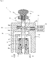
- the bi-stable quick-release valve V according to one embodiment of the present invention in a neutral state is shown in Fig. 1 .
- An actuation rod 9 is slidably accommodated in a guidance 1a of a valve housing
- the actuation rod 9 is connected with a valve head 4 via a connecting element 3.
- the connecting element 3 is a part of the valve actuation rod 9, which extends below the valve head 4.
- the valve head 4 is slidably arranged on said connecting element 3.
- the valve head 4 has a sealing 4a, which is disposed between the valve housing 1 and the valve head 4. Furthermore, a first spring 2 is arranged between the valve housing 1 and the valve head 4 and urges the valve head 4 against a valve seat 5.
- a further recess 6d on the other side of the valve housing 1, where a connecting element 6c rests.
- the recess 6d is also arranged orthogonally relative to the guidance 1a.
- a third spring 6a is arranged between the connecting element 6c and the valve housing 1, which urges the connecting element 6c in the direction of the actuation rod 9.
- the connecting element 6c is able to press a second following member 6b, which also has a spherical shape, against the actuation rod 9.
- the connecting element 6c is further connected to one or more electrical switch(es) 6e, and the movement of the connecting element 6c can actuate the switch(es) 6e.
- the switch(es) 6e is/are in the non-actuated position.
- That part of the actuation rod 9 that is accommodated in the guidance 1a has two grooves: a first groove 9a and a second groove 9b.
- the first groove 9a is arranged above the second groove 9b. Between the first groove 9a and the second groove 9b, there is a ridge 9c.
- the first groove 9a has a semi-circular cross-section, and the second groove 9b has a semi-elliptical cross-section.
- the neutral state which is depicted in Fig. 1 , both, the first following member 10b and the second following member 6b rest in the second groove 9b, as they are biased against it via the second spring 10a and the third spring 6a, respectively.
- the first groove 9a and the second groove 9b and the ridge 9c form a guide track on the actuating rod 9, in which the first following member 10b and the second following member 6b are guided.
- the force exerted by the biasing of the second spring 10 causes the actuation rod 9 to move downward.
- an actuation member 7 is provided on the upper part of the actuation rod 9, an actuation member 7 is provided.
- the actuation member 7 is connected to the actuation rod 9 by means of a fourth spring 8.
- a straight pin 7a which is able to secure the actuation member 7 in its neutral position, and to the actuation rod 9. This allows a downward movement of the actuation member 7. Said movement is limited by the contact between the actuation member 7 and the top surface of the actuation rod 9.
- the shape of the second groove 9b forces the first following member 10b to compress the second spring 10a. Hence, if the actuation rod 9 is moved downwards, the first following member 10b is pressed and moved into the recess 10c.
- Fig. 2 shows the bi-stable quick-release valve V of Fig. 1 in an actuated position.
- the actuation rod 9 has moved downwards and has moved the valve head 4 to an opened position, so that there is a passage between the brake pipe B and the atmosphere O.
- the first following member 10a rests in the first groove 9a
- the second following member 6b rests against the ridge 9c.
- the second following member 6b and the connecting element 6c have been pushed back and the spring 6a is compressed.
- the switch(es)6e is/are in the actuated position.
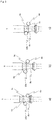
- Fig. 3 shows a detailed view of the actuation rod 9 together with the first following member 10b and the second following member 6b. Also, the first groove 9 and the second groove 9b and their specific shape and the ridge 9c are shown in detail in Fig. 3 .
- Fig. 3 a shows the valve V in its neutral position.
- both, the first following member 10b and the second following member 6b rest in the second groove 9b, which has a quasi-elliptical shape.
- the first following member 10b is disposed above the second following member 6b.
- the second following member 6b is disposed at the lower part of the second groove 9b.
- the actuation rod 9 is forced into the lock-in position by the first following member 10b due to the design of the grooves 9a, 9b and the ridge 9c.
- the resultant force of the following members 10b, 6b press the actuation rod 9 up against the valve housing 1 (not shown here).
- the actuation rod 9 together with its grooves 9a, 9b and its ridge 9c are axis-symmetrical, and hence a rotation around the main axis is permitted.
- Fig. 3 b shows the actuation rod 9 in the dead point.
- the actuation rod 9 has moved downwards.
- the first following member 10b is disposed shortly above the ridge 9c and hence has passed the ridge 9c.
- the second following member 6b is shortly below the ridge 9c.
- the force exerted onto the first following member 10b by the second spring 10a pushes the actuation rod 9 in a downward direction while pushing the first following member 10b into the first groove 9a.
- the resultant force is split into a vertical and a horizontal component.
- Fig. 3 c shows the actuation rod 9 in the actuated position.
- the first following member 10b is disposed in the first groove 9a and snuggly fits into it.
- the second following member 6b however is directly at the ridge 9c.
- the second following member 6b does not move any more.
- the actuation and the operation of the quick-release valve according to the present invention is described more in detail: If the actuating force is less than the specified trigger force in a neutral position, the bi-stable quick-release valve V shall not induce a drop in the brake pipe pressure B, and the bi-stable quick-release valve V will not generate an electrical signal by the switch(es)6e which indicate(s) an emergency brake actuation.
- the actuation member 7 moves downward due to the impact force by pushing it and starts compressing the fourth spring 8.
- the force is insufficient to fully compress the fourth spring 8, so there will be no contact between the actuation member 7 and the top of the actuation rod 9.
- the actuation rod 9 will not force the opening of the valve head 4, and also the switch(es) 6e controlled by the actuation rod 9 via the connecting element 6c will not be actuated.
- the movement of the valve actuation rod 9 is restricted by counter-forces (frictional forces and spring forces) exerted by the first following member 10b which is pressed against the actuation rod 9 by the second spring 9a. These counter-forces cannot be overcome by the force transferred purely by the fourth spring 8.
- the actuation member 7 If the actuation force is released or discontinued, the actuation member 7 returns to its original position due to the spring force exerted by the fourth spring 8.
- the bi-stable quick-release valve V will switch abruptly: Due to the force exerted on the actuation member 7, the actuation member 7 will accelerate downwards, while compressing the fourth spring 8. In this case, a contact between the actuation member 7 and the actuation rod 9 will be accomplished. With the valve actuation rod moving downwards, the counter-forces due to the grooves 9a, 9b will increase and will reach the maximum at the dead point. Hence, the actuation rod 9 will not force the opening of the valve head 4, and the switch(es) 6e controlled by the actuation rod 9 via the connecting element 6c will not be actuated either.
- valve actuation rod 9 pushes the valve head 4 before the actuation rod 9 reaches the dead point and opens it against counter-forces of the first spring 2 and the brake pipe pressure B. Because of the over-compensated design of the valve seat 5, as soon as the valve head 4 is lifted, the resulting force of the pneumatic forces will change its direction and will enhance a further lifting of the valve head 4.
- the opening of the valve V is stable and proceeds immediately. If the valve V is opened, the braking line pressure B and the atmospheric pressure O are connected. In the case of an actuated position, the second following member 6a rests below that point on the ridge 9c, and the electrical switch(es) 6e controlled by the valve actuation rod 9 is/are actuated. In this case, the first following member 10b pressed against the actuation rod 9 by the second spring 10a in this position exerts enough force to counteract the force of the first spring 2. Consequently, the bi-stable quick-release valve is stabilized in the actuated position and cannot move back to the neutral position without further forces.
- the bi-stable quick-release valve V should be re-set to the neutral position, the following actions are necessary:
- the actuation member 7 must be pulled upwards.
- the pulling force acting on the actuation rod 9 must be able to overcome the counter-force of the first following member 10b so that the first following member 10b passes from the actuated position through the dead point to the neutral position.
- the first spring 2 presses the valve head 4 against the valve seat, and hence, the valve V is closed.
- the actuated switch(es)6e controlled by the valve actuation rod 9 is/are then re-set and does not cause an emergency signal any more.
- the present invention is not limited to the above-mentioned embodiment.
- the actuation rod 9 can have any shape and does not have to be rotation-symmetrical. It can have a square-shaped cross-section, and also the grooves 9a, 9b can have a different cross-section, for example a rectangular shape. Also the following members 10b, 6b do not necessarily have to be a spherical shape, they can also have any other shape.
- the present application includes a valve V in particular for applying an emergency brake of a rail vehicle, comprising a valve housing 1, an actuation member 7 which is suitable to be activated by a user, an actuation rod 9 connecting the actuation member with a valve head 4, wherein the valve head 4 is adapted to abut on a valve seat 5, a guidance 1a for guiding the actuation rod 9 being provided within the valve housing 1, a first spring 2 which is adapted to push the valve head 4 against the valve seat 5, wherein the actuation rod 9 comprises a first groove 9a and a second groove 9b, and furthermore, a first following member 10b is provided between the actuation rod 9 and the guidance 1a, being adapted to stably rest in the first groove 9a or the second groove 9b.
- the position of the first following member 10b within the first groove 9a or the second groove 9b determines whether the actuation rod 9 and hence the whole valve V assembly is in the neutral position or the actuated position.
- valve V is a bi-stable quick-release valve, because it does not allow any unstable, "in-between" valve states.
- the bi-stable quick-release valve of the present application opens without delay upon reaching a specified actuation force, and reduces the pressure in the brake pipe with the required pressure gradient.
- actuation force with which the actuation member 7 of the valve is actuated is below a specified trigger force, there is no pressure decrease in the brake pipe pressure, because the valve does not open. Either, a specified trigger force is applied and the valve V fully opens, or a specific trigger force is not reached, and then the valve V does not open. However, under no circumstance an in-between state can occur.
Landscapes
- Engineering & Computer Science (AREA)
- General Engineering & Computer Science (AREA)
- Mechanical Engineering (AREA)
- Transportation (AREA)
- Valves And Accessory Devices For Braking Systems (AREA)
- Mechanically-Actuated Valves (AREA)
Abstract
wherein the actuation rod (9) comprises a first groove (9a) and a second groove (9b),
and furthermore, a first following member (10b) is provided between the actuation rod (9) and the guidance (1a), being adapted to stably rest in the first groove (9a) or the second groove (9b).
Description
- The present invention relates to a quick-release valve for a train in order to provide a safety-lock release mechanism and an electrical feedback. Quick-release valves are usually installed in a driver's cab of railway vehicles and are used for brake actuation in the case of an emergency.
- In prior art, a braking system for commercial vehicles is shown in document
DE 35 44 965 A1 , inter alia including an emergency brake valve, connected to a compressed air reservoir. This emergency brake valve comprises an actuation knob which can be actuated with a hand or a foot and is adapted to initiate an emergency braking. The knob has a protective cover which has to be removed before the actuation of the emergency brake valve. - Furthermore, document
AT 106282 B1 - Quick-release valves as known from prior art enable provoking a partial and temporary valve opening if the actuating force is lower than a specified trigger force. As a result, the pressure in the brake pipe starts decreasing, but it is possible that it stops suddenly if the valve is re-closed, which results in that the brakes are released again.
- Also, it is possible that electrical switches have already been actuated after a partial and temporary valve opening and will continue in an emergency brake actuation signal, even though an emergency braking is no longer present.
- Hence, quick-release valves of prior art may have a state when they are not fully opened or closed, and then, it is possible that they return to their initial state. Prior art quick-release valves hence have clear disadvantages and cannot be handled safely. Furthermore, it is possible that they cannot be fully actuated or are pushed back to the initial position during actuation.
- Hence, prior art quick-release valves have clear disadvantages.
- It is hence an objective of the present application to provide a quick-release valve which avoids or even prevents any unstable ("in-between") valve states.
- This technical problem is solved by a bistable quick-release valve with the features of
claim 1. Further advantageous embodiments of the present invention are subject-matter of the dependent claims. - The present application includes a valve in particular for applying an emergency brake of a rail vehicle, comprising a valve housing, an actuation member which is suitable to be activated by a user, an actuation rod connecting the actuation member with a valve head, wherein the valve head is adapted to abut on the valve seat, a guidance for guiding the actuation rod being provided within the valve housing, a first spring which is adapted to push the valve head against the valve seat,
wherein the actuation rod comprises a first groove and a second groove,
and furthermore, a first following member is provided between the actuation rod and the guidance, being adapted to stably rest in the first groove or the second groove.
The position of the first following member within the first groove or the second groove determines whether the actuation rod and hence the whole valve assembly is in the neutral position or the actuated position. - Hence, the valve according to the present invention is a bi-stable quick-release valve, because it does not allow any unstable, "in-between" valve states. The bi-stable quick-release valve of the present application opens without delay upon reaching a specified actuation force, and reduces the pressure in the brake pipe with the required pressure gradient. If the actuation force with which the actuation member of the valve is actuated is below a specified trigger force, there is no pressure decrease in the brake pipe pressure, because the valve does not open. Either, a specified trigger force is applied and the valve fully opens, or a specific trigger force is not reached, and then the valve does not open. However, under no circumstance an in-between state can occur.
- Preferably, a second following member is provided between the actuation rod and the guidance. This member actuates a switch or more switches which has /have two positions which can hence indicate an emergency brake signal.
- Preferably, the first groove and/or the second groove are radial grooves and extend around the circumference of the actuation rod.
- More preferably, a ridge is provided between the first groove and the second groove. This ridge preferably has a sharp edge so that at least the first following member cannot stably rest on or nearby said ridge, but push the actuation rod either to the neutral or to the actuated position so that the first following member either rests and is otherwise pushed in in the first groove or in the second groove of the actuation rod.
- Preferably, the first groove and/or the second groove have a semi-circular or semi-elliptical shape.
- Further preferably, the first following member and the second following member have a spherical or ellipsoidal shape. More preferably, they are made of metal, e.g. steel.
More preferably, the first following member is pressed against the actuation rod by a second spring which rests in the valve housing. Further preferably, the second following member is pressed against the actuation rod by a third spring which rests in the valve housing. - This design of the following members and the grooves allows that at least the first, preferably also the second following member are pushed and pressed by the respective springs (second spring and third spring) against the actuation rod. Hence, a certain frictional force in the upward or downward direction on the valve actuation rod is generated. The spring force(s) and the frictional force(s) result in the fact that a certain trigger force is required in order to actuate the actuation member.
- Preferably, the first following member is adapted to be able to stably rest in the first groove or the second groove, and/or the second groove is adapted that both the first following member and second following member are able to stably rest in it. Hence, the second groove has a greater longitudinal extension compared to the first groove.
- Preferably, there is a connection member between the third spring and the second following member which is adapted to actuate an electrical switch.
By this means, one or more electrical switch(es)can be actuated, and a warning signal can be provided that an emergency brake has been initiated. - The actuation of the electrical switch(es) is carried out via the displacement of the second following member, which is also driven by the grooves and the ridge of the valve actuation rod. In particular, the shape of the valve actuation rod, in particular dominated by the shape of the first groove and the second groove and the ridge, enables that the second following member rather rests in the first groove or in the second groove. The second following member, however, cannot rest on the ridge, but would be pushed into the first groove or the second groove, respectively. In particular due to this design of the valve actuation member, there is only a neutral position and an actuated position of the valve, i.e. there are two positions. A dead point can be avoided, as the first following
member 10b cannot stably rest on theridge 9c. - More preferably, the actuation member has a hole which is adapted to receive the upper part of the actuation rod, wherein a fourth spring is arranged between the actuation member and the upper part of the actuation rod.
- If the actuation member is moved downward due to the impact force and the fourth spring starts to be compressed, the force is insufficient in order to actuate the whole actuation rod, as the frictional force exerted onto the actuation rod by the first following member is higher than the force exerted by the fourth spring. Hence, if the actuation member is actuated accidentally, the actuation rod is at first not actuated. Even more preferably, the frictional force between the actuation rod and the first following member is higher than the force needed to fully compress the fourth spring. This even enhances the previously described effect.
- Even more preferably, the diameter of the guidance of the valve head is smaller than the diameter of the sealing edge of the valve seat.
- By this measure, the valve is over-compensated. Because of this over-compensated design of the valve seat, as soon as the valve head is lifted, the resultant pneumatic forces will change the direction and will enhance a further lifting of the valve head.
- By overcoming the forces that hold the valve in a closed state, the valve then suddenly opens - a counter-force from the brake pipe pressure is then eliminated. In this way, the downward force, which predominates significantly, accelerates the valve actuation towards the end position.
- More preferably, the valve is adapted to open and/or close the channel between a brake pipe pressure and the atmosphere, so that in an emergency case, the brake pipe pressure can be evacuated and the emergency brake will become active.
- In the following, a preferred embodiment will be explained more in detail with reference to the appended figures.
- Fig. 1
- is a cross-sectional representation of the valve according to the present application in a neutral, non-actuated position.
- Fig. 2
- shows a cross-sectional representation of a valve according to the present application in an actuated position.
- Fig. 3
- shows a detailed view in the arrangement of the first following member and the second following member and the actuation rod in a neutral position, the dead point and in an actuated position.
- The bi-stable quick-release valve V according to one embodiment of the present invention in a neutral state is shown in
Fig. 1 . - An
actuation rod 9 is slidably accommodated in aguidance 1a of a valve housing Theactuation rod 9 is connected with a valve head 4 via a connectingelement 3. The connectingelement 3 is a part of thevalve actuation rod 9, which extends below the valve head 4. There is a pre-defined gap between abuffer plate 3a and the related contact surface of the valve head 4. The valve head 4 is slidably arranged on said connectingelement 3. - The valve head 4 has a
sealing 4a, which is disposed between thevalve housing 1 and the valve head 4. Furthermore, afirst spring 2 is arranged between thevalve housing 1 and the valve head 4 and urges the valve head 4 against avalve seat 5. - In the
guidance 1a of thevalve housing 1, where theactuation rod 9 is guided, there is arecess 10c, where asecond spring 10a is supported; saidsecond spring 10a presses a first followingmember 10b, which has a spherical shape, against theactuation rod 9. Therecess 10c is arranged orthogonally relative to theguidance 1a. - Similarly, there is a
further recess 6d on the other side of thevalve housing 1, where a connectingelement 6c rests. Therecess 6d is also arranged orthogonally relative to theguidance 1a. Athird spring 6a is arranged between the connectingelement 6c and thevalve housing 1, which urges the connectingelement 6c in the direction of theactuation rod 9. The connectingelement 6c is able to press a second followingmember 6b, which also has a spherical shape, against theactuation rod 9. The connectingelement 6c is further connected to one or more electrical switch(es) 6e, and the movement of the connectingelement 6c can actuate the switch(es) 6e. Here, the switch(es) 6e is/are in the non-actuated position. - That part of the
actuation rod 9 that is accommodated in theguidance 1a has two grooves: afirst groove 9a and asecond groove 9b. Thefirst groove 9a is arranged above thesecond groove 9b. Between thefirst groove 9a and thesecond groove 9b, there is aridge 9c. Thefirst groove 9a has a semi-circular cross-section, and thesecond groove 9b has a semi-elliptical cross-section. In the neutral state which is depicted inFig. 1 , both, the first followingmember 10b and the second followingmember 6b rest in thesecond groove 9b, as they are biased against it via thesecond spring 10a and thethird spring 6a, respectively. The forces exerted by thesecond spring 10a and thethird spring 6a to the actuation rod and furthermore the frictional forces result in the fact that a specific trigger force needs to be exerted on theactuation rod 9 in the upward or downward direction in order to move theactuation rod 9 in the upward or downward direction. - The
first groove 9a and thesecond groove 9b and theridge 9c form a guide track on theactuating rod 9, in which the first followingmember 10b and the second followingmember 6b are guided. When the first followingmember 10b surpasses the dead point (i.e. theridge 9c) on the guide track, the force exerted by the biasing of the second spring 10 causes theactuation rod 9 to move downward. This simultaneously causes the second followingmember 6b to be pushed into therecess 6d and actuate the switch(es) 6e. - On the upper part of the
actuation rod 9, anactuation member 7 is provided. Theactuation member 7 is connected to theactuation rod 9 by means of a fourth spring 8. Also, there is astraight pin 7a, which is able to secure theactuation member 7 in its neutral position, and to theactuation rod 9. This allows a downward movement of theactuation member 7. Said movement is limited by the contact between theactuation member 7 and the top surface of theactuation rod 9. - If the
actuation rod 9 is pressed downwards, the shape of thesecond groove 9b forces the first followingmember 10b to compress thesecond spring 10a. Hence, if theactuation rod 9 is moved downwards, the first followingmember 10b is pressed and moved into therecess 10c. -
Fig. 2 shows the bi-stable quick-release valve V ofFig. 1 in an actuated position. Herein, theactuation rod 9 has moved downwards and has moved the valve head 4 to an opened position, so that there is a passage between the brake pipe B and the atmosphere O. Now, the first followingmember 10a rests in thefirst groove 9a, and the second followingmember 6b rests against theridge 9c. Furthermore, the second followingmember 6b and the connectingelement 6c have been pushed back and thespring 6a is compressed. The switch(es)6e is/are in the actuated position. -
Fig. 3 shows a detailed view of theactuation rod 9 together with the first followingmember 10b and the second followingmember 6b. Also, thefirst groove 9 and thesecond groove 9b and their specific shape and theridge 9c are shown in detail inFig. 3 . -
Fig. 3 a) shows the valve V in its neutral position. Herein, both, the first followingmember 10b and the second followingmember 6b rest in thesecond groove 9b, which has a quasi-elliptical shape. The first followingmember 10b is disposed above the second followingmember 6b. The second followingmember 6b is disposed at the lower part of thesecond groove 9b. - Hence, the
actuation rod 9 is forced into the lock-in position by the first followingmember 10b due to the design of thegrooves ridge 9c. The resultant force of the followingmembers actuation rod 9 up against the valve housing 1 (not shown here). Furthermore, it can be seen that theactuation rod 9 together with itsgrooves ridge 9c are axis-symmetrical, and hence a rotation around the main axis is permitted. -
Fig. 3 b) shows theactuation rod 9 in the dead point. Herein, compared toFig. 3 a) , theactuation rod 9 has moved downwards. The first followingmember 10b is disposed shortly above theridge 9c and hence has passed theridge 9c. The second followingmember 6b is shortly below theridge 9c. The force exerted onto the first followingmember 10b by thesecond spring 10a (not shown here) pushes theactuation rod 9 in a downward direction while pushing the first followingmember 10b into thefirst groove 9a. The resultant force is split into a vertical and a horizontal component. -
Fig. 3 c) shows theactuation rod 9 in the actuated position. Herein, the first followingmember 10b is disposed in thefirst groove 9a and snuggly fits into it. The second followingmember 6b however is directly at theridge 9c. However, as the first followingmember 10b has reached a stable position, the second followingmember 6b does not move any more. - In the following, the actuation and the operation of the quick-release valve according to the present invention is described more in detail:
If the actuating force is less than the specified trigger force in a neutral position, the bi-stable quick-release valve V shall not induce a drop in the brake pipe pressure B, and the bi-stable quick-release valve V will not generate an electrical signal by the switch(es)6e which indicate(s) an emergency brake actuation. - The
actuation member 7 moves downward due to the impact force by pushing it and starts compressing the fourth spring 8. However, in this case, the force is insufficient to fully compress the fourth spring 8, so there will be no contact between theactuation member 7 and the top of theactuation rod 9. Hence, theactuation rod 9 will not force the opening of the valve head 4, and also the switch(es) 6e controlled by theactuation rod 9 via the connectingelement 6c will not be actuated. Herein, the movement of thevalve actuation rod 9 is restricted by counter-forces (frictional forces and spring forces) exerted by the first followingmember 10b which is pressed against theactuation rod 9 by thesecond spring 9a. These counter-forces cannot be overcome by the force transferred purely by the fourth spring 8. - If the actuation force is released or discontinued, the
actuation member 7 returns to its original position due to the spring force exerted by the fourth spring 8. - If the actuation force becomes greater than the specific trigger force, the bi-stable quick-release valve V will switch abruptly: Due to the force exerted on the
actuation member 7, theactuation member 7 will accelerate downwards, while compressing the fourth spring 8. In this case, a contact between theactuation member 7 and theactuation rod 9 will be accomplished. With the valve actuation rod moving downwards, the counter-forces due to thegrooves actuation rod 9 will not force the opening of the valve head 4, and the switch(es) 6e controlled by theactuation rod 9 via the connectingelement 6c will not be actuated either. - To achieve a really bi-stable valve, it has to be ensured that the actuation rod will surpass the dead point automatically. This is indeed ensured by the quick-release valve V of the present invention. The full actuation and the sudden opening of the valve head 4 are accomplished by the following four effects:
- The
valve actuation rod 9 pushes the valve head 4 before theactuation rod 9 reaches the dead point and opens it against counter-forces of thefirst spring 2 and the brake pipe pressure B. Because of the over-compensated design of thevalve seat 5, as soon as the valve head 4 is lifted, the resulting force of the pneumatic forces will change its direction and will enhance a further lifting of the valve head 4. - As the forces that hold the valve head 4 in a closed state have been overcome, the valve head 4 now suddenly opens - and a counter-force from the brake pipe pressure B is eliminated. By this design, the downward forces, which now predominate significantly, accelerate the valve V actuation downwards towards the end position.
- The downward movement of the
valve actuation rod 9 and the valve head 4 is complemented by the expansion of the fourth spring 8, so that the wholevalve actuation rod 9 can pass the dead point. Hence, the energy invested during actuation of theactuation member 7 is transmitted by the fourth spring 8 to theactuation rod 9 and the valve head 4 when additional energy is needed to push theactuation rod 9 over the dead point, i.e. theridge 9c. - As soon as the valve head 4 opens, pneumatic forces exerted by the brake pipe pressure B further accelerate the lifting of the valve head 4. Hence, the momentum of the valve head 4 is transmitted by the connecting
element 3 and thebuffer plate 3a to theactuation rod 9, thereby facilitating surpassing of the dead point and thus causing the final actuation of thevalve actuation rod 9. This means that the forces that push thevalve actuation rod 9 downwards, can overcome the counter-force as exerted to the valve actuation rod by the first followingmember 10b and also the second followingmember 6b. The inertia of the downward moving parts prevents a deadlock between the two stable positions of the valve. Hence, only two stable positions are possible. - Once the first following
member 10b surpasses the dead point on theridge 9c, it will force the further downward movement of theactuation rod 9. - Due to the above-mentioned facts, the opening of the valve V is stable and proceeds immediately. If the valve V is opened, the braking line pressure B and the atmospheric pressure O are connected. In the case of an actuated position, the second following
member 6a rests below that point on theridge 9c, and the electrical switch(es) 6e controlled by thevalve actuation rod 9 is/are actuated. In this case, the first followingmember 10b pressed against theactuation rod 9 by thesecond spring 10a in this position exerts enough force to counteract the force of thefirst spring 2. Consequently, the bi-stable quick-release valve is stabilized in the actuated position and cannot move back to the neutral position without further forces. - If the bi-stable quick-release valve V should be re-set to the neutral position, the following actions are necessary:
Theactuation member 7 must be pulled upwards. The pulling force acting on theactuation rod 9 must be able to overcome the counter-force of the first followingmember 10b so that the first followingmember 10b passes from the actuated position through the dead point to the neutral position. Then, also thefirst spring 2 presses the valve head 4 against the valve seat, and hence, the valve V is closed. The actuated switch(es)6e controlled by thevalve actuation rod 9 is/are then re-set and does not cause an emergency signal any more. - The present invention is not limited to the above-mentioned embodiment.
- The
actuation rod 9 can have any shape and does not have to be rotation-symmetrical. It can have a square-shaped cross-section, and also thegrooves members - The present application includes a valve V in particular for applying an emergency brake of a rail vehicle, comprising a
valve housing 1, anactuation member 7 which is suitable to be activated by a user, anactuation rod 9 connecting the actuation member with a valve head 4, wherein the valve head 4 is adapted to abut on avalve seat 5, aguidance 1a for guiding theactuation rod 9 being provided within thevalve housing 1, afirst spring 2 which is adapted to push the valve head 4 against thevalve seat 5,
wherein theactuation rod 9 comprises afirst groove 9a and asecond groove 9b, and furthermore, a first followingmember 10b is provided between theactuation rod 9 and theguidance 1a, being adapted to stably rest in thefirst groove 9a or thesecond groove 9b.
The position of the first followingmember 10b within thefirst groove 9a or thesecond groove 9b determines whether theactuation rod 9 and hence the whole valve V assembly is in the neutral position or the actuated position. - Furthermore, there is a second following
member 6b, which is pressed against theactuation rod 9 by athird spring 6a which rests in thevalve housing 1.
Further, there is a connectingelement 6c between thethird spring 6a and the second followingmember 6b, which is adapted to actuate one or more electrical switch(es) 6e, with which an emergency signal can be output.
Hence, the valve V according to the present invention is a bi-stable quick-release valve, because it does not allow any unstable, "in-between" valve states. The bi-stable quick-release valve of the present application opens without delay upon reaching a specified actuation force, and reduces the pressure in the brake pipe with the required pressure gradient. If the actuation force with which theactuation member 7 of the valve is actuated is below a specified trigger force, there is no pressure decrease in the brake pipe pressure, because the valve does not open. Either, a specified trigger force is applied and the valve V fully opens, or a specific trigger force is not reached, and then the valve V does not open. However, under no circumstance an in-between state can occur. -
- V
- Valve
- 1
- Valve housing
- 1a
- Guidance
- 2
- First spring
- 3
- Connecting element
- 3a
- Buffer plate
- 4
- Valve head
- 4a
- Sealing
- 5
- Valve seat
- 6a
- Third spring
- 6b
- Second following member
- 6c
- Connecting element
- 6d
- Recess
- 6e
- Switch(es)
- 7
- Actuation member
- 7a
- Straight pin
- 8
- Fourth spring
- 9
- Actuation rod
- 9a
- First Groove
- 9b
- Second Groove
- 9c
- Ridge
- 10a
- Second spring
- 10b
- First following member
- BP
- Brake pipe pressure
- O
- Atmosphere
Claims (13)
- Valve (V), in particular for applying an emergency brake of a rail vehicle, comprising:a valve housing (1);an actuation member (7) which is suitable to be actuated by a user;an actuation rod (9), connecting the actuation member (7) with a valve head (4), wherein the valve head (4) is adapted to abut on a valve seat (5);a guidance (1a) for guiding the actuation rod (4) being provided within the valve housing (1),a first spring (2) which is adapted to push the valve head (4) against the valve seat (5);wherein the actuation rod (9) comprises a first groove (9a) and a second groove (9b);and furthermore a first following member (10b) is provided between the actuation rod (9) and the guidance (1a), being adapted to stably rest in the first groove (9a) or the second groove (9b).
- Valve (V) according to claim 1, wherein a second following member (6b) is provided between the actuation rod (9) and the guidance (1a).
- Valve (V) according to claim 1 or 2, wherein the first groove (9a) and / or the second groove (9b) are radial grooves and extend around the circumference of the actuation rod (9).
- Valve (V) according to one of the previous claims, wherein a ridge (9c) is provided between the first groove (9a) and the second groove (9b).
- Valve (V) according to one of the previous claims, wherein the first groove (9a) and / or the second groove (9b) have a semi-circular or a semi-elliptical shape.
- Valve (V) according to one of the previous claims, wherein the first following member (10b) and/or the second following member (6b) have a spherical or ellipsoidal shape.
- Valve (V) according to one of the previous claims, wherein the first following member (10b) is adapted to be able to stably rest in the first groove (9a) or the second groove (9b), and/or the first groove (9a) is adapted that both the first following member (10b) and second following member (6b) are able to stably rest in it.
- Valve (V) according to one of the previous claims, wherein the first following member (10b) is pressed against the actuation rod (9) by a second spring (10a) which rests in the valve housing (1), and / or wherein the second following member (6b) is pressed against the actuation rod (9) by a third spring (6a) which rests in the valve housing (1).
- Valve (V) according to claim 8, wherein there is a connecting element (6c) between the third spring (6a) and the second following member (6b), which is adapted to actuate one or more electrical switch(es) (6e), wherein the connecting element (6c) is accommodated in a recess (6d) provided within the valve housing (1).
- Valve (V) according to one of the previous claims, wherein the actuation member (7) has a hole which is adapted to receive the upper part of the actuation rod (9), wherein a fourth spring (8) is arranged between the actuation member (7) and the upper part of the actuation rod (9).
- Valve (V) according to claim 11, wherein the resultant force between the actuation rod (9) and the first following member (10b) is higher than the force needed to fully compress the fourth spring (8).
- Valve (V) according to one of the previous claims, wherein the diameter of the guidance of the valve head (4) is smaller than the diameter of the sealing edge of the valve seat (5).
- Valve (V) according to one of the previous claims, wherein the valve (1) is adapted to open and/or close the channel between a brake pipe pressure line (B) and the atmosphere (O).
Priority Applications (3)
| Application Number | Priority Date | Filing Date | Title |
|---|---|---|---|
| EP20174402.6A EP3909821B1 (en) | 2020-05-13 | 2020-05-13 | Bi-stable quick-release valve |
| US17/319,763 US11499646B2 (en) | 2020-05-13 | 2021-05-13 | Bi-stable quick-release valve |
| CN202110519844.7A CN113738880B (en) | 2020-05-13 | 2021-05-13 | Bistable quick release valve |
Applications Claiming Priority (1)
| Application Number | Priority Date | Filing Date | Title |
|---|---|---|---|
| EP20174402.6A EP3909821B1 (en) | 2020-05-13 | 2020-05-13 | Bi-stable quick-release valve |
Publications (2)
| Publication Number | Publication Date |
|---|---|
| EP3909821A1 true EP3909821A1 (en) | 2021-11-17 |
| EP3909821B1 EP3909821B1 (en) | 2023-03-08 |
Family
ID=70968708
Family Applications (1)
| Application Number | Title | Priority Date | Filing Date |
|---|---|---|---|
| EP20174402.6A Active EP3909821B1 (en) | 2020-05-13 | 2020-05-13 | Bi-stable quick-release valve |
Country Status (3)
| Country | Link |
|---|---|
| US (1) | US11499646B2 (en) |
| EP (1) | EP3909821B1 (en) |
| CN (1) | CN113738880B (en) |
Cited By (1)
| Publication number | Priority date | Publication date | Assignee | Title |
|---|---|---|---|---|
| CN114834420A (en) * | 2022-05-13 | 2022-08-02 | 中车齐齐哈尔车辆有限公司 | Accelerated brake valve and air control valve with same |
Families Citing this family (4)
| Publication number | Priority date | Publication date | Assignee | Title |
|---|---|---|---|---|
| WO2020176837A1 (en) * | 2019-02-28 | 2020-09-03 | Restek Corporation | Proportional solenoid valve having zero current during intermittent state hold conditions |
| US11773997B2 (en) * | 2019-04-01 | 2023-10-03 | Cameron International Corporation | Valve gate eutectic lock |
| DE102020003751A1 (en) * | 2020-06-23 | 2021-12-23 | BlERl Hydraulik AG | Valve device |
| DE102020003973A1 (en) * | 2020-07-02 | 2022-01-05 | Hydac Fluidtechnik Gmbh | Valve device |
Citations (8)
| Publication number | Priority date | Publication date | Assignee | Title |
|---|---|---|---|---|
| GB808577A (en) * | 1956-03-27 | 1959-02-04 | Rotol Ltd | Improvements in or relating to hydraulic safety valves |
| GB2159249A (en) * | 1984-05-24 | 1985-11-27 | Fuentetaja Julio Bouzas | Gas valve |
| DE3544965A1 (en) | 1985-12-19 | 1987-06-25 | Bosch Gmbh Robert | Pressure-medium actuated brake system |
| EP0491172A1 (en) * | 1990-12-18 | 1992-06-24 | Knorr-Bremse Ag | Emergency brake device for air pressure brakes for railway vehicles |
| DE19913380C1 (en) * | 1999-03-24 | 2000-05-25 | Knorr Bremse Systeme | Arrangement for controlled actuation of valve switching element, especially for vehicle container switching valve has pressure arrangement for displacing switching element into safety position |
| EP1132275A2 (en) * | 2000-02-22 | 2001-09-12 | KNORR-BREMSE SYSTEME FÜR NUTZFAHRZEUGE GmbH | Hand operated valve lock device, especially for commercial vehicle parking brake valve |
| DE102007005980A1 (en) * | 2007-02-07 | 2008-08-14 | Knorr-Bremse Systeme für Nutzfahrzeuge GmbH | Device for the controlled actuation of a switching element of a valve |
| CN203585347U (en) * | 2013-09-27 | 2014-05-07 | 重庆盾铭电磁阀有限公司 | Electromagnetic rapid cut-off valve |
Family Cites Families (14)
| Publication number | Priority date | Publication date | Assignee | Title |
|---|---|---|---|---|
| US1568159A (en) * | 1924-11-10 | 1926-01-05 | Heywood Charles Frederic | High-pressure valve |
| AT106282B (en) | 1925-12-03 | 1927-04-25 | Gottlieb Ackermann | Emergency brake valve for railway air brakes. |
| US2200396A (en) * | 1938-01-25 | 1940-05-14 | Cary W Martin | Antenna system |
| US2285655A (en) * | 1941-01-02 | 1942-06-09 | Victor Equipment Co | Fluid controlling valve |
| US3879091A (en) * | 1974-01-21 | 1975-04-22 | Caterpillar Tractor Co | Parking brake control system |
| US4451095A (en) * | 1982-06-10 | 1984-05-29 | Clark Equipment Company | Auxiliary release device for a hydraulic pressure releasable brake |
| US6186477B1 (en) * | 1999-05-05 | 2001-02-13 | Airsep Corporation | Gas by-pass valve |
| JP4226607B2 (en) * | 2006-02-22 | 2009-02-18 | 本田技研工業株式会社 | Default device for actuator for variable valve mechanism |
| CN101092894B (en) * | 2007-07-16 | 2010-08-25 | 马银良 | Position restricted mechanism for drive piston in device of slowing down speed of engine |
| CN101696742B (en) * | 2009-10-21 | 2010-12-08 | 潘兆铿 | Multi-channel stepped electric gas control valve |
| DE102016014872A1 (en) * | 2016-12-14 | 2018-06-14 | Daimler Ag | Valve drive device |
| CN206479874U (en) * | 2017-01-24 | 2017-09-08 | 重庆西山科技股份有限公司 | Foot controller |
| US10641140B2 (en) * | 2017-05-12 | 2020-05-05 | Caterpillar Inc. | Hydraulic early engine exhaust valve opening system |
| CN107489804B (en) * | 2017-09-27 | 2019-04-09 | 宁波国创机车装备有限公司 | A kind of emergency braking vent valve and its spool locking method |
-
2020
- 2020-05-13 EP EP20174402.6A patent/EP3909821B1/en active Active
-
2021
- 2021-05-13 CN CN202110519844.7A patent/CN113738880B/en active Active
- 2021-05-13 US US17/319,763 patent/US11499646B2/en active Active
Patent Citations (8)
| Publication number | Priority date | Publication date | Assignee | Title |
|---|---|---|---|---|
| GB808577A (en) * | 1956-03-27 | 1959-02-04 | Rotol Ltd | Improvements in or relating to hydraulic safety valves |
| GB2159249A (en) * | 1984-05-24 | 1985-11-27 | Fuentetaja Julio Bouzas | Gas valve |
| DE3544965A1 (en) | 1985-12-19 | 1987-06-25 | Bosch Gmbh Robert | Pressure-medium actuated brake system |
| EP0491172A1 (en) * | 1990-12-18 | 1992-06-24 | Knorr-Bremse Ag | Emergency brake device for air pressure brakes for railway vehicles |
| DE19913380C1 (en) * | 1999-03-24 | 2000-05-25 | Knorr Bremse Systeme | Arrangement for controlled actuation of valve switching element, especially for vehicle container switching valve has pressure arrangement for displacing switching element into safety position |
| EP1132275A2 (en) * | 2000-02-22 | 2001-09-12 | KNORR-BREMSE SYSTEME FÜR NUTZFAHRZEUGE GmbH | Hand operated valve lock device, especially for commercial vehicle parking brake valve |
| DE102007005980A1 (en) * | 2007-02-07 | 2008-08-14 | Knorr-Bremse Systeme für Nutzfahrzeuge GmbH | Device for the controlled actuation of a switching element of a valve |
| CN203585347U (en) * | 2013-09-27 | 2014-05-07 | 重庆盾铭电磁阀有限公司 | Electromagnetic rapid cut-off valve |
Cited By (1)
| Publication number | Priority date | Publication date | Assignee | Title |
|---|---|---|---|---|
| CN114834420A (en) * | 2022-05-13 | 2022-08-02 | 中车齐齐哈尔车辆有限公司 | Accelerated brake valve and air control valve with same |
Also Published As
| Publication number | Publication date |
|---|---|
| EP3909821B1 (en) | 2023-03-08 |
| CN113738880A (en) | 2021-12-03 |
| US20210404569A1 (en) | 2021-12-30 |
| CN113738880B (en) | 2024-10-01 |
| US11499646B2 (en) | 2022-11-15 |
Similar Documents
| Publication | Publication Date | Title |
|---|---|---|
| EP3909821B1 (en) | Bi-stable quick-release valve | |
| KR100562831B1 (en) | Parking lock for vehicle automatic transmission | |
| US4978178A (en) | Automatic self-resetting parking brake | |
| KR101984341B1 (en) | Spring brake cylinder with emergency release device | |
| JPS62137260A (en) | Braking pressure generator | |
| JPS6134567B2 (en) | ||
| HU200823B (en) | Three-way hydraulic valve | |
| CN106573604A (en) | Brake booster for brake system of vehicle | |
| US3939727A (en) | Mechanical actuating system | |
| US5417143A (en) | Lock-out mechanism for empty/load changeover valve | |
| US20220055597A1 (en) | Brake cylinder comprimising a locking device for mechanical brake force locking | |
| US4158398A (en) | Dump valve assembly | |
| WO2012111830A1 (en) | Parking brake device | |
| JP2655681B2 (en) | Brake pressure adjustment device | |
| CN113696861A (en) | Parking actuating mechanism for vehicle and vehicle comprising same | |
| EP3299229B1 (en) | An automatic parking brake | |
| US3938406A (en) | Force limiting device for a motor vehicle parking brake | |
| EP0654387B1 (en) | Fluid pressure operable spring force actuators | |
| EP0257145B1 (en) | Manually operable control valves | |
| JP4005136B2 (en) | Fluid device for controlling brake, clutch and brake clutch | |
| PL277743A1 (en) | Acceleration device for indirectly operated hydraulic brakes | |
| JP2002507519A (en) | Pneumatic booster with automatic position control assistance | |
| JP3248402U (en) | Car emergency stop device | |
| US8621861B2 (en) | Actuating armature | |
| CN105593585B (en) | locking device for valve |
Legal Events
| Date | Code | Title | Description |
|---|---|---|---|
| PUAI | Public reference made under article 153(3) epc to a published international application that has entered the european phase |
Free format text: ORIGINAL CODE: 0009012 |
|
| STAA | Information on the status of an ep patent application or granted ep patent |
Free format text: STATUS: THE APPLICATION HAS BEEN PUBLISHED |
|
| AK | Designated contracting states |
Kind code of ref document: A1 Designated state(s): AL AT BE BG CH CY CZ DE DK EE ES FI FR GB GR HR HU IE IS IT LI LT LU LV MC MK MT NL NO PL PT RO RS SE SI SK SM TR |
|
| B565 | Issuance of search results under rule 164(2) epc |
Effective date: 20201027 |
|
| STAA | Information on the status of an ep patent application or granted ep patent |
Free format text: STATUS: REQUEST FOR EXAMINATION WAS MADE |
|
| 17P | Request for examination filed |
Effective date: 20220517 |
|
| RBV | Designated contracting states (corrected) |
Designated state(s): AL AT BE BG CH CY CZ DE DK EE ES FI FR GB GR HR HU IE IS IT LI LT LU LV MC MK MT NL NO PL PT RO RS SE SI SK SM TR |
|
| GRAP | Despatch of communication of intention to grant a patent |
Free format text: ORIGINAL CODE: EPIDOSNIGR1 |
|
| STAA | Information on the status of an ep patent application or granted ep patent |
Free format text: STATUS: GRANT OF PATENT IS INTENDED |
|
| RIC1 | Information provided on ipc code assigned before grant |
Ipc: F16K 1/00 20060101ALI20220830BHEP Ipc: B60T 15/04 20060101ALI20220830BHEP Ipc: F16K 17/04 20060101ALI20220830BHEP Ipc: B60T 17/20 20060101AFI20220830BHEP |
|
| INTG | Intention to grant announced |
Effective date: 20220927 |
|
| GRAS | Grant fee paid |
Free format text: ORIGINAL CODE: EPIDOSNIGR3 |
|
| GRAA | (expected) grant |
Free format text: ORIGINAL CODE: 0009210 |
|
| STAA | Information on the status of an ep patent application or granted ep patent |
Free format text: STATUS: THE PATENT HAS BEEN GRANTED |
|
| AK | Designated contracting states |
Kind code of ref document: B1 Designated state(s): AL AT BE BG CH CY CZ DE DK EE ES FI FR GB GR HR HU IE IS IT LI LT LU LV MC MK MT NL NO PL PT RO RS SE SI SK SM TR |
|
| REG | Reference to a national code |
Ref country code: CH Ref legal event code: EP Ref country code: AT Ref legal event code: REF Ref document number: 1552400 Country of ref document: AT Kind code of ref document: T Effective date: 20230315 |
|
| REG | Reference to a national code |
Ref country code: DE Ref legal event code: R096 Ref document number: 602020008632 Country of ref document: DE |
|
| REG | Reference to a national code |
Ref country code: IE Ref legal event code: FG4D |
|
| REG | Reference to a national code |
Ref country code: LT Ref legal event code: MG9D |
|
| REG | Reference to a national code |
Ref country code: NL Ref legal event code: MP Effective date: 20230308 |
|
| PG25 | Lapsed in a contracting state [announced via postgrant information from national office to epo] |
Ref country code: RS Free format text: LAPSE BECAUSE OF FAILURE TO SUBMIT A TRANSLATION OF THE DESCRIPTION OR TO PAY THE FEE WITHIN THE PRESCRIBED TIME-LIMIT Effective date: 20230308 Ref country code: NO Free format text: LAPSE BECAUSE OF FAILURE TO SUBMIT A TRANSLATION OF THE DESCRIPTION OR TO PAY THE FEE WITHIN THE PRESCRIBED TIME-LIMIT Effective date: 20230608 Ref country code: LV Free format text: LAPSE BECAUSE OF FAILURE TO SUBMIT A TRANSLATION OF THE DESCRIPTION OR TO PAY THE FEE WITHIN THE PRESCRIBED TIME-LIMIT Effective date: 20230308 Ref country code: LT Free format text: LAPSE BECAUSE OF FAILURE TO SUBMIT A TRANSLATION OF THE DESCRIPTION OR TO PAY THE FEE WITHIN THE PRESCRIBED TIME-LIMIT Effective date: 20230308 Ref country code: HR Free format text: LAPSE BECAUSE OF FAILURE TO SUBMIT A TRANSLATION OF THE DESCRIPTION OR TO PAY THE FEE WITHIN THE PRESCRIBED TIME-LIMIT Effective date: 20230308 Ref country code: ES Free format text: LAPSE BECAUSE OF FAILURE TO SUBMIT A TRANSLATION OF THE DESCRIPTION OR TO PAY THE FEE WITHIN THE PRESCRIBED TIME-LIMIT Effective date: 20230308 |
|
| REG | Reference to a national code |
Ref country code: AT Ref legal event code: MK05 Ref document number: 1552400 Country of ref document: AT Kind code of ref document: T Effective date: 20230308 |
|
| PG25 | Lapsed in a contracting state [announced via postgrant information from national office to epo] |
Ref country code: SE Free format text: LAPSE BECAUSE OF FAILURE TO SUBMIT A TRANSLATION OF THE DESCRIPTION OR TO PAY THE FEE WITHIN THE PRESCRIBED TIME-LIMIT Effective date: 20230308 Ref country code: NL Free format text: LAPSE BECAUSE OF FAILURE TO SUBMIT A TRANSLATION OF THE DESCRIPTION OR TO PAY THE FEE WITHIN THE PRESCRIBED TIME-LIMIT Effective date: 20230308 Ref country code: GR Free format text: LAPSE BECAUSE OF FAILURE TO SUBMIT A TRANSLATION OF THE DESCRIPTION OR TO PAY THE FEE WITHIN THE PRESCRIBED TIME-LIMIT Effective date: 20230609 Ref country code: FI Free format text: LAPSE BECAUSE OF FAILURE TO SUBMIT A TRANSLATION OF THE DESCRIPTION OR TO PAY THE FEE WITHIN THE PRESCRIBED TIME-LIMIT Effective date: 20230308 |
|
| PG25 | Lapsed in a contracting state [announced via postgrant information from national office to epo] |
Ref country code: SM Free format text: LAPSE BECAUSE OF FAILURE TO SUBMIT A TRANSLATION OF THE DESCRIPTION OR TO PAY THE FEE WITHIN THE PRESCRIBED TIME-LIMIT Effective date: 20230308 Ref country code: RO Free format text: LAPSE BECAUSE OF FAILURE TO SUBMIT A TRANSLATION OF THE DESCRIPTION OR TO PAY THE FEE WITHIN THE PRESCRIBED TIME-LIMIT Effective date: 20230308 Ref country code: PT Free format text: LAPSE BECAUSE OF FAILURE TO SUBMIT A TRANSLATION OF THE DESCRIPTION OR TO PAY THE FEE WITHIN THE PRESCRIBED TIME-LIMIT Effective date: 20230710 Ref country code: EE Free format text: LAPSE BECAUSE OF FAILURE TO SUBMIT A TRANSLATION OF THE DESCRIPTION OR TO PAY THE FEE WITHIN THE PRESCRIBED TIME-LIMIT Effective date: 20230308 Ref country code: AT Free format text: LAPSE BECAUSE OF FAILURE TO SUBMIT A TRANSLATION OF THE DESCRIPTION OR TO PAY THE FEE WITHIN THE PRESCRIBED TIME-LIMIT Effective date: 20230308 |
|
| PG25 | Lapsed in a contracting state [announced via postgrant information from national office to epo] |
Ref country code: SK Free format text: LAPSE BECAUSE OF FAILURE TO SUBMIT A TRANSLATION OF THE DESCRIPTION OR TO PAY THE FEE WITHIN THE PRESCRIBED TIME-LIMIT Effective date: 20230308 Ref country code: PL Free format text: LAPSE BECAUSE OF FAILURE TO SUBMIT A TRANSLATION OF THE DESCRIPTION OR TO PAY THE FEE WITHIN THE PRESCRIBED TIME-LIMIT Effective date: 20230308 Ref country code: IS Free format text: LAPSE BECAUSE OF FAILURE TO SUBMIT A TRANSLATION OF THE DESCRIPTION OR TO PAY THE FEE WITHIN THE PRESCRIBED TIME-LIMIT Effective date: 20230708 |
|
| REG | Reference to a national code |
Ref country code: DE Ref legal event code: R097 Ref document number: 602020008632 Country of ref document: DE |
|
| REG | Reference to a national code |
Ref country code: CH Ref legal event code: PL |
|
| PLBE | No opposition filed within time limit |
Free format text: ORIGINAL CODE: 0009261 |
|
| STAA | Information on the status of an ep patent application or granted ep patent |
Free format text: STATUS: NO OPPOSITION FILED WITHIN TIME LIMIT |
|
| PG25 | Lapsed in a contracting state [announced via postgrant information from national office to epo] |
Ref country code: MC Free format text: LAPSE BECAUSE OF FAILURE TO SUBMIT A TRANSLATION OF THE DESCRIPTION OR TO PAY THE FEE WITHIN THE PRESCRIBED TIME-LIMIT Effective date: 20230308 |
|
| REG | Reference to a national code |
Ref country code: BE Ref legal event code: MM Effective date: 20230531 |
|
| PG25 | Lapsed in a contracting state [announced via postgrant information from national office to epo] |
Ref country code: SI Free format text: LAPSE BECAUSE OF FAILURE TO SUBMIT A TRANSLATION OF THE DESCRIPTION OR TO PAY THE FEE WITHIN THE PRESCRIBED TIME-LIMIT Effective date: 20230308 Ref country code: MC Free format text: LAPSE BECAUSE OF FAILURE TO SUBMIT A TRANSLATION OF THE DESCRIPTION OR TO PAY THE FEE WITHIN THE PRESCRIBED TIME-LIMIT Effective date: 20230308 Ref country code: LU Free format text: LAPSE BECAUSE OF NON-PAYMENT OF DUE FEES Effective date: 20230513 Ref country code: LI Free format text: LAPSE BECAUSE OF NON-PAYMENT OF DUE FEES Effective date: 20230531 Ref country code: DK Free format text: LAPSE BECAUSE OF FAILURE TO SUBMIT A TRANSLATION OF THE DESCRIPTION OR TO PAY THE FEE WITHIN THE PRESCRIBED TIME-LIMIT Effective date: 20230308 Ref country code: CH Free format text: LAPSE BECAUSE OF NON-PAYMENT OF DUE FEES Effective date: 20230531 |
|
| 26N | No opposition filed |
Effective date: 20231211 |
|
| REG | Reference to a national code |
Ref country code: IE Ref legal event code: MM4A |
|
| PG25 | Lapsed in a contracting state [announced via postgrant information from national office to epo] |
Ref country code: IE Free format text: LAPSE BECAUSE OF NON-PAYMENT OF DUE FEES Effective date: 20230513 |
|
| PG25 | Lapsed in a contracting state [announced via postgrant information from national office to epo] |
Ref country code: IE Free format text: LAPSE BECAUSE OF NON-PAYMENT OF DUE FEES Effective date: 20230513 |
|
| PG25 | Lapsed in a contracting state [announced via postgrant information from national office to epo] |
Ref country code: BE Free format text: LAPSE BECAUSE OF NON-PAYMENT OF DUE FEES Effective date: 20230531 |
|
| PG25 | Lapsed in a contracting state [announced via postgrant information from national office to epo] |
Ref country code: BG Free format text: LAPSE BECAUSE OF FAILURE TO SUBMIT A TRANSLATION OF THE DESCRIPTION OR TO PAY THE FEE WITHIN THE PRESCRIBED TIME-LIMIT Effective date: 20230308 |
|
| PG25 | Lapsed in a contracting state [announced via postgrant information from national office to epo] |
Ref country code: BG Free format text: LAPSE BECAUSE OF FAILURE TO SUBMIT A TRANSLATION OF THE DESCRIPTION OR TO PAY THE FEE WITHIN THE PRESCRIBED TIME-LIMIT Effective date: 20230308 |
|
| GBPC | Gb: european patent ceased through non-payment of renewal fee |
Effective date: 20240513 |
|
| PG25 | Lapsed in a contracting state [announced via postgrant information from national office to epo] |
Ref country code: GB Free format text: LAPSE BECAUSE OF NON-PAYMENT OF DUE FEES Effective date: 20240513 |
|
| PGFP | Annual fee paid to national office [announced via postgrant information from national office to epo] |
Ref country code: DE Payment date: 20250528 Year of fee payment: 6 |
|
| PGFP | Annual fee paid to national office [announced via postgrant information from national office to epo] |
Ref country code: IT Payment date: 20250522 Year of fee payment: 6 |
|
| PGFP | Annual fee paid to national office [announced via postgrant information from national office to epo] |
Ref country code: FR Payment date: 20250526 Year of fee payment: 6 |
|
| PG25 | Lapsed in a contracting state [announced via postgrant information from national office to epo] |
Ref country code: CY Free format text: LAPSE BECAUSE OF FAILURE TO SUBMIT A TRANSLATION OF THE DESCRIPTION OR TO PAY THE FEE WITHIN THE PRESCRIBED TIME-LIMIT; INVALID AB INITIO Effective date: 20200513 |
|
| PGFP | Annual fee paid to national office [announced via postgrant information from national office to epo] |
Ref country code: CZ Payment date: 20250424 Year of fee payment: 6 |
|
| PG25 | Lapsed in a contracting state [announced via postgrant information from national office to epo] |
Ref country code: HU Free format text: LAPSE BECAUSE OF FAILURE TO SUBMIT A TRANSLATION OF THE DESCRIPTION OR TO PAY THE FEE WITHIN THE PRESCRIBED TIME-LIMIT; INVALID AB INITIO Effective date: 20200513 |
|
| PG25 | Lapsed in a contracting state [announced via postgrant information from national office to epo] |
Ref country code: TR Free format text: LAPSE BECAUSE OF FAILURE TO SUBMIT A TRANSLATION OF THE DESCRIPTION OR TO PAY THE FEE WITHIN THE PRESCRIBED TIME-LIMIT Effective date: 20230308 |