EP3909682B1 - Method and roller mill for thermomechanically activating a clay mixture - Google Patents
Method and roller mill for thermomechanically activating a clay mixture Download PDFInfo
- Publication number
- EP3909682B1 EP3909682B1 EP20174635.1A EP20174635A EP3909682B1 EP 3909682 B1 EP3909682 B1 EP 3909682B1 EP 20174635 A EP20174635 A EP 20174635A EP 3909682 B1 EP3909682 B1 EP 3909682B1
- Authority
- EP
- European Patent Office
- Prior art keywords
- grinding
- mill
- roller mill
- roller
- bowl
- Prior art date
- Legal status (The legal status is an assumption and is not a legal conclusion. Google has not performed a legal analysis and makes no representation as to the accuracy of the status listed.)
- Active
Links
- 239000000203 mixture Substances 0.000 title claims description 73
- 239000004927 clay Substances 0.000 title claims description 72
- 238000000034 method Methods 0.000 title claims description 30
- 230000003213 activating effect Effects 0.000 title description 7
- 238000000227 grinding Methods 0.000 claims description 203
- 239000002826 coolant Substances 0.000 claims description 72
- 230000004913 activation Effects 0.000 claims description 21
- 238000009413 insulation Methods 0.000 claims description 18
- 150000004760 silicates Chemical class 0.000 claims description 8
- QAOWNCQODCNURD-UHFFFAOYSA-L Sulfate Chemical compound [O-]S([O-])(=O)=O QAOWNCQODCNURD-UHFFFAOYSA-L 0.000 claims description 4
- 238000001816 cooling Methods 0.000 description 52
- 239000007789 gas Substances 0.000 description 36
- 239000004568 cement Substances 0.000 description 28
- 239000010410 layer Substances 0.000 description 23
- XLYOFNOQVPJJNP-UHFFFAOYSA-N water Substances O XLYOFNOQVPJJNP-UHFFFAOYSA-N 0.000 description 22
- 238000001994 activation Methods 0.000 description 20
- 239000002245 particle Substances 0.000 description 19
- 239000003570 air Substances 0.000 description 14
- 239000000654 additive Substances 0.000 description 12
- 229910052615 phyllosilicate Inorganic materials 0.000 description 12
- 239000000463 material Substances 0.000 description 11
- 230000000996 additive effect Effects 0.000 description 10
- 230000008569 process Effects 0.000 description 8
- 230000000694 effects Effects 0.000 description 7
- 238000010438 heat treatment Methods 0.000 description 7
- NLYAJNPCOHFWQQ-UHFFFAOYSA-N kaolin Chemical compound O.O.O=[Al]O[Si](=O)O[Si](=O)O[Al]=O NLYAJNPCOHFWQQ-UHFFFAOYSA-N 0.000 description 7
- 238000006243 chemical reaction Methods 0.000 description 6
- 238000005906 dihydroxylation reaction Methods 0.000 description 6
- 229910052900 illite Inorganic materials 0.000 description 6
- 229910052622 kaolinite Inorganic materials 0.000 description 6
- VGIBGUSAECPPNB-UHFFFAOYSA-L nonaaluminum;magnesium;tripotassium;1,3-dioxido-2,4,5-trioxa-1,3-disilabicyclo[1.1.1]pentane;iron(2+);oxygen(2-);fluoride;hydroxide Chemical compound [OH-].[O-2].[O-2].[O-2].[O-2].[O-2].[F-].[Mg+2].[Al+3].[Al+3].[Al+3].[Al+3].[Al+3].[Al+3].[Al+3].[Al+3].[Al+3].[K+].[K+].[K+].[Fe+2].O1[Si]2([O-])O[Si]1([O-])O2.O1[Si]2([O-])O[Si]1([O-])O2.O1[Si]2([O-])O[Si]1([O-])O2.O1[Si]2([O-])O[Si]1([O-])O2.O1[Si]2([O-])O[Si]1([O-])O2.O1[Si]2([O-])O[Si]1([O-])O2.O1[Si]2([O-])O[Si]1([O-])O2 VGIBGUSAECPPNB-UHFFFAOYSA-L 0.000 description 6
- 230000008646 thermal stress Effects 0.000 description 6
- 229910004283 SiO 4 Inorganic materials 0.000 description 5
- 239000013590 bulk material Substances 0.000 description 5
- 125000002887 hydroxy group Chemical group [H]O* 0.000 description 5
- 229910052500 inorganic mineral Inorganic materials 0.000 description 5
- 239000011707 mineral Substances 0.000 description 5
- VYPSYNLAJGMNEJ-UHFFFAOYSA-N silicon dioxide Inorganic materials O=[Si]=O VYPSYNLAJGMNEJ-UHFFFAOYSA-N 0.000 description 5
- 230000035882 stress Effects 0.000 description 5
- CURLTUGMZLYLDI-UHFFFAOYSA-N Carbon dioxide Chemical compound O=C=O CURLTUGMZLYLDI-UHFFFAOYSA-N 0.000 description 4
- BPQQTUXANYXVAA-UHFFFAOYSA-N Orthosilicate Chemical compound [O-][Si]([O-])([O-])[O-] BPQQTUXANYXVAA-UHFFFAOYSA-N 0.000 description 4
- -1 calcium silicate hydrates Chemical class 0.000 description 4
- 239000013078 crystal Substances 0.000 description 4
- 239000000428 dust Substances 0.000 description 4
- 235000012239 silicon dioxide Nutrition 0.000 description 4
- 229910000831 Steel Inorganic materials 0.000 description 3
- 239000012080 ambient air Substances 0.000 description 3
- 238000005280 amorphization Methods 0.000 description 3
- 150000001768 cations Chemical class 0.000 description 3
- 239000002734 clay mineral Substances 0.000 description 3
- GUJOJGAPFQRJSV-UHFFFAOYSA-N dialuminum;dioxosilane;oxygen(2-);hydrate Chemical compound O.[O-2].[O-2].[O-2].[Al+3].[Al+3].O=[Si]=O.O=[Si]=O.O=[Si]=O.O=[Si]=O GUJOJGAPFQRJSV-UHFFFAOYSA-N 0.000 description 3
- 239000010445 mica Substances 0.000 description 3
- 229910052618 mica group Inorganic materials 0.000 description 3
- 229910052901 montmorillonite Inorganic materials 0.000 description 3
- 239000010453 quartz Substances 0.000 description 3
- 239000010959 steel Substances 0.000 description 3
- 239000011230 binding agent Substances 0.000 description 2
- AXCZMVOFGPJBDE-UHFFFAOYSA-L calcium dihydroxide Chemical compound [OH-].[OH-].[Ca+2] AXCZMVOFGPJBDE-UHFFFAOYSA-L 0.000 description 2
- 239000000920 calcium hydroxide Substances 0.000 description 2
- 229910001861 calcium hydroxide Inorganic materials 0.000 description 2
- 239000000378 calcium silicate Substances 0.000 description 2
- 229910052918 calcium silicate Inorganic materials 0.000 description 2
- 229910002092 carbon dioxide Inorganic materials 0.000 description 2
- 239000010433 feldspar Substances 0.000 description 2
- 239000010440 gypsum Substances 0.000 description 2
- 229910052602 gypsum Inorganic materials 0.000 description 2
- 229910052739 hydrogen Inorganic materials 0.000 description 2
- 238000004519 manufacturing process Methods 0.000 description 2
- 238000003801 milling Methods 0.000 description 2
- 239000003921 oil Substances 0.000 description 2
- 229910001414 potassium ion Inorganic materials 0.000 description 2
- 238000011084 recovery Methods 0.000 description 2
- 238000007789 sealing Methods 0.000 description 2
- 229910052710 silicon Inorganic materials 0.000 description 2
- 239000010703 silicon Substances 0.000 description 2
- 239000007787 solid Substances 0.000 description 2
- 229910001018 Cast iron Inorganic materials 0.000 description 1
- 229910001208 Crucible steel Inorganic materials 0.000 description 1
- 241001251094 Formica Species 0.000 description 1
- FYYHWMGAXLPEAU-UHFFFAOYSA-N Magnesium Chemical compound [Mg] FYYHWMGAXLPEAU-UHFFFAOYSA-N 0.000 description 1
- XUIMIQQOPSSXEZ-UHFFFAOYSA-N Silicon Chemical compound [Si] XUIMIQQOPSSXEZ-UHFFFAOYSA-N 0.000 description 1
- 230000009471 action Effects 0.000 description 1
- 239000012615 aggregate Substances 0.000 description 1
- XAGFODPZIPBFFR-UHFFFAOYSA-N aluminium Chemical compound [Al] XAGFODPZIPBFFR-UHFFFAOYSA-N 0.000 description 1
- 229910052782 aluminium Inorganic materials 0.000 description 1
- 230000009286 beneficial effect Effects 0.000 description 1
- 230000005540 biological transmission Effects 0.000 description 1
- 230000015572 biosynthetic process Effects 0.000 description 1
- 238000007664 blowing Methods 0.000 description 1
- 238000001354 calcination Methods 0.000 description 1
- 239000001569 carbon dioxide Substances 0.000 description 1
- 239000012159 carrier gas Substances 0.000 description 1
- 239000000919 ceramic Substances 0.000 description 1
- 229910010293 ceramic material Inorganic materials 0.000 description 1
- 238000001311 chemical methods and process Methods 0.000 description 1
- 239000003245 coal Substances 0.000 description 1
- 239000011248 coating agent Substances 0.000 description 1
- 238000000576 coating method Methods 0.000 description 1
- 238000010276 construction Methods 0.000 description 1
- 239000000498 cooling water Substances 0.000 description 1
- 238000002425 crystallisation Methods 0.000 description 1
- 230000008025 crystallization Effects 0.000 description 1
- 230000007547 defect Effects 0.000 description 1
- 230000001627 detrimental effect Effects 0.000 description 1
- 238000009792 diffusion process Methods 0.000 description 1
- YGANSGVIUGARFR-UHFFFAOYSA-N dipotassium dioxosilane oxo(oxoalumanyloxy)alumane oxygen(2-) Chemical compound [O--].[K+].[K+].O=[Si]=O.O=[Al]O[Al]=O YGANSGVIUGARFR-UHFFFAOYSA-N 0.000 description 1
- 238000001035 drying Methods 0.000 description 1
- 229920001971 elastomer Polymers 0.000 description 1
- 239000000806 elastomer Substances 0.000 description 1
- 238000005265 energy consumption Methods 0.000 description 1
- 238000000605 extraction Methods 0.000 description 1
- 239000010419 fine particle Substances 0.000 description 1
- 239000012530 fluid Substances 0.000 description 1
- 239000001257 hydrogen Substances 0.000 description 1
- 239000011229 interlayer Substances 0.000 description 1
- 150000002500 ions Chemical class 0.000 description 1
- 239000007788 liquid Substances 0.000 description 1
- 239000011777 magnesium Substances 0.000 description 1
- 229910052749 magnesium Inorganic materials 0.000 description 1
- 238000004137 mechanical activation Methods 0.000 description 1
- 230000007246 mechanism Effects 0.000 description 1
- 238000010303 mechanochemical reaction Methods 0.000 description 1
- 238000010327 methods by industry Methods 0.000 description 1
- 239000011490 mineral wool Substances 0.000 description 1
- 229910052627 muscovite Inorganic materials 0.000 description 1
- 125000004430 oxygen atom Chemical group O* 0.000 description 1
- 229910001737 paragonite Inorganic materials 0.000 description 1
- 230000000149 penetrating effect Effects 0.000 description 1
- 239000011148 porous material Substances 0.000 description 1
- 230000036316 preload Effects 0.000 description 1
- 230000005855 radiation Effects 0.000 description 1
- 239000002994 raw material Substances 0.000 description 1
- 229910052616 serpentine group Inorganic materials 0.000 description 1
- 239000000377 silicon dioxide Substances 0.000 description 1
- 229910021647 smectite Inorganic materials 0.000 description 1
- 229910000269 smectite group Inorganic materials 0.000 description 1
- 150000003467 sulfuric acid derivatives Chemical class 0.000 description 1
- 229910021653 sulphate ion Inorganic materials 0.000 description 1
- 238000007725 thermal activation Methods 0.000 description 1
- 230000000930 thermomechanical effect Effects 0.000 description 1
- 230000009466 transformation Effects 0.000 description 1
- 238000000844 transformation Methods 0.000 description 1
- 238000009834 vaporization Methods 0.000 description 1
- 230000008016 vaporization Effects 0.000 description 1
- 229910052902 vermiculite Inorganic materials 0.000 description 1
- 239000010455 vermiculite Substances 0.000 description 1
- 235000019354 vermiculite Nutrition 0.000 description 1
Images

Classifications
-
- B—PERFORMING OPERATIONS; TRANSPORTING
- B02—CRUSHING, PULVERISING, OR DISINTEGRATING; PREPARATORY TREATMENT OF GRAIN FOR MILLING
- B02C—CRUSHING, PULVERISING, OR DISINTEGRATING IN GENERAL; MILLING GRAIN
- B02C23/00—Auxiliary methods or auxiliary devices or accessories specially adapted for crushing or disintegrating not provided for in preceding groups or not specially adapted to apparatus covered by a single preceding group
- B02C23/18—Adding fluid, other than for crushing or disintegrating by fluid energy
- B02C23/24—Passing gas through crushing or disintegrating zone
- B02C23/26—Passing gas through crushing or disintegrating zone characterised by point of gas entry or exit or by gas flow path
-
- C—CHEMISTRY; METALLURGY
- C04—CEMENTS; CONCRETE; ARTIFICIAL STONE; CERAMICS; REFRACTORIES
- C04B—LIME, MAGNESIA; SLAG; CEMENTS; COMPOSITIONS THEREOF, e.g. MORTARS, CONCRETE OR LIKE BUILDING MATERIALS; ARTIFICIAL STONE; CERAMICS; REFRACTORIES; TREATMENT OF NATURAL STONE
- C04B20/00—Use of materials as fillers for mortars, concrete or artificial stone according to more than one of groups C04B14/00 - C04B18/00 and characterised by shape or grain distribution; Treatment of materials according to more than one of the groups C04B14/00 - C04B18/00 specially adapted to enhance their filling properties in mortars, concrete or artificial stone; Expanding or defibrillating materials
- C04B20/02—Treatment
- C04B20/04—Heat treatment
-
- B—PERFORMING OPERATIONS; TRANSPORTING
- B02—CRUSHING, PULVERISING, OR DISINTEGRATING; PREPARATORY TREATMENT OF GRAIN FOR MILLING
- B02C—CRUSHING, PULVERISING, OR DISINTEGRATING IN GENERAL; MILLING GRAIN
- B02C15/00—Disintegrating by milling members in the form of rollers or balls co-operating with rings or discs
- B02C15/001—Air flow directing means positioned on the periphery of the horizontally rotating milling surface
-
- B—PERFORMING OPERATIONS; TRANSPORTING
- B02—CRUSHING, PULVERISING, OR DISINTEGRATING; PREPARATORY TREATMENT OF GRAIN FOR MILLING
- B02C—CRUSHING, PULVERISING, OR DISINTEGRATING IN GENERAL; MILLING GRAIN
- B02C15/00—Disintegrating by milling members in the form of rollers or balls co-operating with rings or discs
- B02C15/003—Shape or construction of discs or rings
-
- B—PERFORMING OPERATIONS; TRANSPORTING
- B02—CRUSHING, PULVERISING, OR DISINTEGRATING; PREPARATORY TREATMENT OF GRAIN FOR MILLING
- B02C—CRUSHING, PULVERISING, OR DISINTEGRATING IN GENERAL; MILLING GRAIN
- B02C15/00—Disintegrating by milling members in the form of rollers or balls co-operating with rings or discs
- B02C15/007—Mills with rollers pressed against a rotary horizontal disc
-
- B—PERFORMING OPERATIONS; TRANSPORTING
- B02—CRUSHING, PULVERISING, OR DISINTEGRATING; PREPARATORY TREATMENT OF GRAIN FOR MILLING
- B02C—CRUSHING, PULVERISING, OR DISINTEGRATING IN GENERAL; MILLING GRAIN
- B02C15/00—Disintegrating by milling members in the form of rollers or balls co-operating with rings or discs
- B02C15/06—Mills with rollers forced against the interior of a rotary ring, e.g. under spring action
-
- C—CHEMISTRY; METALLURGY
- C04—CEMENTS; CONCRETE; ARTIFICIAL STONE; CERAMICS; REFRACTORIES
- C04B—LIME, MAGNESIA; SLAG; CEMENTS; COMPOSITIONS THEREOF, e.g. MORTARS, CONCRETE OR LIKE BUILDING MATERIALS; ARTIFICIAL STONE; CERAMICS; REFRACTORIES; TREATMENT OF NATURAL STONE
- C04B14/00—Use of inorganic materials as fillers, e.g. pigments, for mortars, concrete or artificial stone; Treatment of inorganic materials specially adapted to enhance their filling properties in mortars, concrete or artificial stone
- C04B14/02—Granular materials, e.g. microballoons
- C04B14/04—Silica-rich materials; Silicates
- C04B14/10—Clay
-
- C—CHEMISTRY; METALLURGY
- C04—CEMENTS; CONCRETE; ARTIFICIAL STONE; CERAMICS; REFRACTORIES
- C04B—LIME, MAGNESIA; SLAG; CEMENTS; COMPOSITIONS THEREOF, e.g. MORTARS, CONCRETE OR LIKE BUILDING MATERIALS; ARTIFICIAL STONE; CERAMICS; REFRACTORIES; TREATMENT OF NATURAL STONE
- C04B28/00—Compositions of mortars, concrete or artificial stone, containing inorganic binders or the reaction product of an inorganic and an organic binder, e.g. polycarboxylate cements
- C04B28/02—Compositions of mortars, concrete or artificial stone, containing inorganic binders or the reaction product of an inorganic and an organic binder, e.g. polycarboxylate cements containing hydraulic cements other than calcium sulfates
-
- C—CHEMISTRY; METALLURGY
- C04—CEMENTS; CONCRETE; ARTIFICIAL STONE; CERAMICS; REFRACTORIES
- C04B—LIME, MAGNESIA; SLAG; CEMENTS; COMPOSITIONS THEREOF, e.g. MORTARS, CONCRETE OR LIKE BUILDING MATERIALS; ARTIFICIAL STONE; CERAMICS; REFRACTORIES; TREATMENT OF NATURAL STONE
- C04B7/00—Hydraulic cements
- C04B7/12—Natural pozzuolanas; Natural pozzuolana cements; Artificial pozzuolanas or artificial pozzuolana cements other than those obtained from waste or combustion residues, e.g. burned clay; Treating inorganic materials to improve their pozzuolanic characteristics
- C04B7/13—Mixtures thereof with inorganic cementitious materials, e.g. Portland cements
-
- C—CHEMISTRY; METALLURGY
- C04—CEMENTS; CONCRETE; ARTIFICIAL STONE; CERAMICS; REFRACTORIES
- C04B—LIME, MAGNESIA; SLAG; CEMENTS; COMPOSITIONS THEREOF, e.g. MORTARS, CONCRETE OR LIKE BUILDING MATERIALS; ARTIFICIAL STONE; CERAMICS; REFRACTORIES; TREATMENT OF NATURAL STONE
- C04B2103/00—Function or property of ingredients for mortars, concrete or artificial stone
- C04B2103/0068—Ingredients with a function or property not provided for elsewhere in C04B2103/00
- C04B2103/0088—Compounds chosen for their latent hydraulic characteristics, e.g. pozzuolanes
Definitions
- the present invention relates to a method for mechanochemically activating a clay mixture and a related roller mill.
- Cement concrete is used worldwide in construction, which comprises the binder cement, water and aggregate. Cement additives can be used for economic and ecological reasons. The aim is to reduce the clinker content in cement or concrete in order to reduce CO2 emissions. In addition, additional sources of raw materials can be tapped for the production of cement.
- the DE 10 2016 005 285 B3 discloses a method of activating clays as an additive for concrete, in which the clay is first crushed in a crushing stage, and then activated in a multi-cyclone cyclonic heat exchanger.
- clay is first ground, and then preheated and finally fed into a calcining furnace.
- heat-treated clay material is ground separately.
- EP 2 253 600 A1 discloses a cement having cement substitutes comprising separately heat treated clay.
- the invention provides a method of mechanochemically activating a clay mixture comprising grinding the clay mixture in a mill at a temperature, the temperature being in a temperature range of from 300°C (degrees Celsius) to 1000°C.
- the clay mixture has the aforesaid temperature during milling. This causes a thermo-mechanical activation of the clay mixture.
- the method according to the invention brings about, in particular, a dehydroxylation of the phyllosilicates contained in the clay mixture.
- Phyllosilicates are primarily made up of silicon (SiO 4 ) tetrahedron layers, aluminum (AlO 6 ) octahedron layers and/or magnesium (MgO 6 ) octahedron layers, the OH bands or hydroxyl groups exhibit.
- the result is a thermally assisted mechanochemical activation of the clay mixture, so that when used as a cement additive or cement clinker substitute, it is more susceptible to a pozzolanic reaction.
- a pozzolanic reaction calcium silicate hydrates in particular are formed from the released, reactive silicon ions of the activated clay mixture and the calcium hydroxide of the pore solution of the cement.
- the clay mixture is at a temperature in a temperature range from 400 °C to 1000 °C, more particularly at a temperature in a temperature range from 450 °C to 950 °C, advantageously at a temperature in a temperature range from 450 °C to 600 °C C, further advantageously ground at a temperature in a temperature range from 500°C to 550°C. Since the particles are comminuted when the clay mixture is ground, a larger surface area for heat transfer from a heating medium, in particular hot gas, to the particles can be made possible. In addition, the heat conduction path from the surface to the inside of the particles can be reduced. This allows the particles to be heated faster and with less energy consumption.
- the water released during the mechanochemical activation can be drained off better.
- grinding can take place in different temperature ranges. At a temperature in a temperature range of 550° C. to 700° C., advantageous activation of kaolinite is made possible. At a temperature in a temperature range of 800° C. to 900° C., advantageous activation of montmorillonite is made possible. At a temperature in a temperature range from 900° C. to 1000° C., advantageous activation of illite is made possible.
- a grinding pressure of greater than 350 kN (kilo-newtons) per square meter is provided, and in particular less than 2000 kN per square meter.
- a grinding pressure of 800 kN to 1000 kN per square meter is provided when grinding the clay mixture.
- the mill is a vertical roller mill, in particular a vertical roller mill.
- the temperature range according to the invention can be provided in a targeted manner in the grinding area, in particular in vertical roller mills, in which the configurations described below, which are advantageous for grinding operation at such elevated temperatures, can be provided.
- the method according to the invention can be carried out in a ball mill, hammer mill, roller mill, in particular high-pressure roller mill, or roller mill.
- the clay mixture consists of at least 25 percent by mass, advantageously at least 50 percent by mass, of thermally activatable phyllosilicates. Further advantageously, the clay mixture consists of at least 70 percent by mass of thermally activatable phyllosilicates. In one embodiment of the method, the clay mixture consists of at least 90 percent by mass of thermally activatable phyllosilicates.
- the layered silicates are two-layer silicates such as kaolinite or the serpentine group, three-layer silicates such as mica, illite, smectite, montmorillonite, and/or four-layer silicates such as the dichlorite group.
- phyllosilicates usually do not occur in the pure phase, but contain accompanying minerals such as quartz and feldspar, which can be beneficial or detrimental to activation.
- Kaolinite has a dioctahedral two-layer structure consisting of SiO 4 tetrahedra and AlO 6 octahedra. At the outer tips of the octahedron are hydroxyl groups that form hydrogen bonds to the oxygen atoms in the next tetrahedron layer. The free tetrahedron tips of the SiO 4 layer combine with the OH groups of the octahedron layer and saturate the Al3 + cations of the octahedron layer. These two mechanisms result in the connection of a tetrahedron layer with an octahedron layer.
- hydroxyl ions are split off from the octahedron layer as part of the dehydroxylation and the crystalline structure of the kaolinite becomes disordered structure transferred.
- Illite and mica have a dioctahedral, and more rarely trioctahedral, three-layer structure consisting of an AlO 6 octahedral layer between two SiO 4 tetrahedral layers.
- the three-layer packages are connected via K + ions as interlayer cations.
- the K + ion can be predominantly replaced by H 3 O + ions.
- the hydroxyl groups are arranged between the two SiO 4 tetrahedron layers. This also causes the significantly higher dehydroxylation temperature for illite, advantageously between 900°C and 1000°C.
- Various activation temperatures may be required for mica minerals. In the case of muscovite, structural transformations already occur at 500 °C, while no activation occurs in paragonite at 900 °C.
- Montmorillonite is a dioctahedral three-layer silicate, which is occupied in an intermediate layer with exchangeable cations and water molecules, and whose optimal activation temperature is between 800 °C and 900 °C.
- Clay mixtures composed of quartz-containing clays with various proportions of phyllosilicates and accompanying minerals are advantageously used as cement clinker substitutes because of their high worldwide availability.
- Clay mixture of at least 90% by mass of clay minerals with a high proportion of layered silicate.
- the clay mixture has a sulfate content of less than 3 percent by mass.
- the clay mixture has a sulfate content of less than 2 percent by mass.
- the clay mixture can contain 1% by mass of sulfates.
- the clay mixture accordingly has little or no gypsum content.
- the clay mixture is ground in the mill and hot gas flows continuously through the mill. Since the hot gas has only a low moisture content, the water released in the clay mixture can be effectively removed, which accelerates the mechanochemical activation.
- the supplied hot gas has in particular a temperature of 300°C to 1000°C, advantageously a temperature between 400°C and 1000°C, further advantageously a temperature between 500°C and 750°C.
- cooling medium in particular cooling air or water or steam
- the clay mixture can thus be heated, and at the same time temperature-critical components of the mill can be cooled by the cooling medium.
- the cooling medium can be fed directly to components of the mill that are to be cooled outside of the grinding chamber.
- a cement substitute mixture comprising at least 6 percent by mass and at most 90 percent by mass of a binder can be produced by the method according to the invention described above.
- the cement mixture may comprise at least 6% by mass of a cement additive produced by the method according to the invention described above.
- the cement mixture contains at most 90% by mass of this cement additive. More particularly, the cement mixture has at most 50 percent by mass of this cement additive.
- the cement mixture contains at most 35% by mass of this cement additive. In one embodiment, the cement mixture has at most 20% by mass of the cement additive. In another embodiment, the cement mixture comprises at least 21% by mass of the cement additive.
- the clay mixture fed to the mill is in particular in the form of a particulate bulk material.
- clay consists primarily of mineral particles smaller than 20 ⁇ m and a silicate clay mineral content with particle sizes smaller than 2 ⁇ m.
- at least 50% of the particles of the clay mixture fed to the mill have a size between 0.2 microns and 9 microns. These particles can be connected to form conglomerates.
- the mixed clay fed to the mill has a BET surface area of between 5 and 42 square meters per gram.
- the clay mixture advantageously has particle sizes of 2 microns to 5 microns.
- the grinding according to the invention is therefore not primarily used for comminution, but rather to mechanically support the chemical reaction of dehydroxylation and furthermore, in particular, the amorphization of the crystalline structures.
- the phyllosilicates of the clay mixture can have about 13 to 19 percent by mass of water of crystallization before activation according to the invention.
- activation of the clay mixture can take place in particular with a lower supply of thermal energy than in the case of conventional heating without grinding as taught in the prior art.
- the clay mixture can be heated efficiently and water released from the clay mixture can be removed quickly, which increases the efficiency of the activation.
- the present invention further provides a roller mill, in particular for the thermally assisted mechanochemical activation of a clay mixture, the roller mill comprising a drive, a grinding table, a grinding table and grinding rollers.
- the grinding table is arranged on the drive, the drive being designed to drive the grinding table so that the grinding rollers roll on the grinding table.
- openings are provided in the edge area of the grinding table in order to allow the cooling medium to flow through.
- the openings are advantageously provided in the lower region of the grinding bowl in order to allow cooling medium to enter the interior of the grinding bowl.
- the openings can be provided in the upper area of the grinding table, in particular in an area below the bearing surface for the grinding table.
- the thermal stress on the mill can thus be reduced.
- the cooling medium is guided in particular through the grinding table in order to cool areas that are particularly at risk of heat, primarily areas with low material thicknesses, sensitive components or areas that are exposed to high thermal output. This advantageously achieves an equalization of the temperature levels.
- the roller mill is a vertical roller mill, in particular a vertical roller mill.
- the roller mill has a sifter that only leaves particles that have reached a certain degree of fineness out of the mill. Particles that are too coarse are fed into another grinding process.
- the cooling medium inlet enables the grinding table to be cooled in a targeted manner, particularly in its lower area.
- the drive includes a drive motor and a gear.
- the grinding bowl is advantageously arranged on a gear flange.
- cooling medium be introduced into the interior of the grinding bowl through the openings in order to enable advantageous cooling there, but a special cooling effect also occurs in the area of the openings.
- several openings are provided along the circumferential direction, so that a circumferential area with an increased cooling effect is advantageously provided in the grinding bowl, so that heat conduction through this area to the drive is reduced.
- the grinding table has a contact surface with which the grinding table stands on the drive, the openings being provided as cutouts in the contact surface of the grinding table.
- the openings are therefore designed to be open to the contact area.
- the heat conducting surface between the grinding table and the drive can thus be reduced.
- the heat conduction between the grinding table and the drive can thus be reduced, so that despite the high temperatures inside the roller mill, only a small amount of heat is transferred to its drive.
- this also makes it possible at the same time to conduct cooling medium directly to the transmission output flange and thus to cool it in a targeted manner.
- the openings are provided as evenly spaced, arcade-shaped openings in the lower contact surface of the grinding bowl.
- the upper area of the radially outer collar of the grinding bowl is coated with hot gas. This limits the heating of the grinding bowl to a small extent.
- the grinding table which forms a wear area, in the upper area of the grinding table.
- the at least one or more wearing parts that form the grinding table can only partially, in particular rest on ridge-shaped areas to reduce the heat transfer through thermal conduction.
- the non-supporting areas can be provided or filled with thermal insulation, preferably made of mineral wool, in order to reduce the heat transfer there as well.
- the grinding table has cooling, which leads to an equalization of the temperature of the various areas of the grinding table, in particular the areas that are mechanically highly stressed by the grinding force and/or by thermal stresses.
- the component temperature can be kept in a range in which the component material has sufficient strength and structural stability.
- the grinding bowl can be provided with at least one cooling channel or several cooling channels, which guide a cooling medium in a targeted manner into the stressed areas.
- the cooling ducts can be arranged in particular in the less stressed areas, and a cooling medium flows through them, which is directed into the stressed areas.
- This cooling medium can be gaseous or liquid and can be pumped either under pressure or under pressure.
- the cooling medium can be fed to the outside of the grinding table via a feed line or directly from the ambient air of the mill.
- the cooling medium is evenly distributed in a ring shape in the area to be cooled.
- the cooling medium advantageously flows through an annular area between a hot gas space arranged below the grinding space and a lower cylindrical or conical part of the grinding bowl.
- the part of the cooling channel facing the hot gas space is provided with thermal insulation in order to transfer only small amounts of heat there, whether by convection to the cooling medium or by thermal radiation from the hot wall.
- the cooling medium enters a plate-shaped upper part of the grinding table forming the grinding table at the outer edge and exits in the inner area.
- the usually hotter part of the grinding table is thus better cooled than the typically cooler radially inner part.
- the radial temperature differences in the grinding table are thus reduced, advantageously essentially balanced out. Overall, the temperature is lowered so that the stress caused by thermal stresses is reduced and possible structural problems in the material of the grinding bowl are also avoided.
- Another effect is the higher strength of the material at the lower temperatures.
- the heated cooling medium can be conveyed downwards within the space enclosed by the grinding bowl and exit again in the lower area through one or more openings, in particular from an annular channel around the lower area of the mill.
- These openings in the grinding table neck wall as well as the inner wall of the grinding table neck are advantageously thermally insulated in order not to cause thermal irregularities in the grinding table neck and to reduce the heat load on the drive.
- the cooling medium is then conveyed to the outside of the mill and, if necessary, put to further use, for example to heat recovery or, in particular in the case of ambient air, to a burner of a hot gas generator as process gas.
- the roller mill comprises a grinding table, on the outer circumference of which a thermal insulation element is provided at least in certain areas.
- the thermal insulation element can be a thermal insulation coating on the outside of the grinding bowl.
- the heat insulation element can be a heat protection plate applied to the outside of the grinding bowl.
- the at least one heat protection plate is screwed onto the grinding bowl from the outside.
- hot gas is blown past the outside of the grinding table into the grinding chamber. The at least one thermal insulation element thus prevents excessive heating of the grinding bowl and thus of the drive.
- the at least one heat insulation element is provided predominantly in the upper half of the grinding bowl. In particular, a lower area of the grinding table is free of thermal insulation elements.
- At least one local nozzle for supplying cooling medium is provided in the interior of the roller mill.
- the local nozzle enables particularly heated areas or particularly heat-sensitive areas to be cooled locally.
- the cooling medium can in particular be cooling air.
- water is only introduced in such a way that the moisture in the area of the ground material is not increased.
- At least one cooling line is provided locally, through which a coolant flows.
- the coolant is pumped through the at least one cooling line.
- Veil cooling or film cooling can be effected by the local nozzle.
- impingement cooling with the cooling medium preventing hot fluids from directly impinging on the component to be cooled.
- a partial flow of the cooling medium can be used, for example generated by a narrow sealing gap with free jet effect.
- the pressure in the cooling medium can be increased to at least 2 bar, advantageously to 4 bar to 8 bar.
- the cooling compressed air can be fed to a grinding table and/or roller seal through a separate cooling flow line.
- At least one heat shield in particular in the form of a heat shield, is provided in front of at least one hot gas outlet.
- the heat shield can allow the hot gas flowing into the mill to be distributed and reduce local heating.
- the heat shield is advantageously provided around the entire circumference of the hot gas space.
- the heat shield can delimit the hot gas space from a space for cooling medium.
- the heat shield can have or consist of a thermal insulation element.
- the grinding roller is rotatably mounted on a grinding roller axis, and cooling medium is supplied through or along the grinding roller axis.
- cooling medium prevents dust generated by the grinding from contaminating the grinding roller bearings.
- at least one cooling medium opening is arranged axially in the direction of the interior of the mill in front of the roller seal. This can prevent dust from reaching the grinding roller bearing.
- at least one cooling medium opening can be arranged between grinding roller bearings that are axially spaced apart from one another. A higher pressure and a flow of air out of the bearing area are thus generated in the advantageously at least partially sealed bearing area. This further prevents dust from penetrating into the grinding roller bearings.
- the bearings can be cooled using oil cooling.
- the grinding table and the grinding table can be designed integrally. Alternatively, the grinding table can also be connected to the grinding table as a separate component.
- the grinding table is attached to the grinding table by an elastic element, the elastic element being designed to compensate for different thermal expansions between the grinding table and the grinding table.
- the elastic element comprises an elastically mounted pin or an elastically mounted clamping element.
- the roller mill may include a nozzle ring that extends radially outside of the grinding table, the nozzle ring being attached to the mill housing by an elastic element, the elastic element being designed to compensate for different thermal expansions between the nozzle ring and the mill housing.
- the elastic element comprises an elastically mounted pin or an elastically mounted clamping element.
- the mill housing can be insulated from the outside and/or inside to keep heat in the process.
- An insulation inside the mill housing is advantageously designed as heat-resistant armouring. However, this also enables the housing material to be protected from heat.
- a lining can also be used here.
- armor can be provided on the inside of the mill housing and insulation can be provided on the outside of the mill housing.
- insulation can be provided on the inside of the mill housing, and armor can be provided on the inside of the insulation.
- Ceramic materials can be used in the roller mill, particularly in the area of sliding surfaces and bearings.
- the roller mill is designed such that hot gas at a first temperature is fed into the interior of the mill, and hot gas at a second temperature is additionally fed in locally in the interior of the mill, the second temperature being higher than the first temperature.
- the necessary temperature in the grinding area can be kept constant. In the grinding area, there is a high conversion of the clay mixture, which first has to be brought to the desired temperature and takes heat from the hot gas for the activation energy of the clay mixture.
- the temperature will advantageously be maintained at a high level until the water split off has diffused out of the clay mixture.
- the hot gas can be kept at least partially in an internal circuit in the mill. However, sufficient hot gas should be discharged from the mill to discharge the separated water from the mill. In particular, an afterburner in the Area of the nozzle ring are provided to keep the temperature of the hot gas high in front of the classifier.
- the housing of the roller mill is segmented and designed with expansion joints.
- the separator can be supported separately from the housing. This allows different thermal expansions to be compensated.
- the housing of the mill is advantageously made from a highly heat-resistant, in particular austenitic, steel.
- the nozzle ring is advantageously made from a highly heat-resistant, in particular austenitic, steel.
- the grinding table and/or the roller body are made in particular from cast iron.
- the grinding table and/or the roller body can be made of steel, advantageously made of a high-temperature, in particular austenitic, cast steel.
- a forced convection cooling jacket is provided around the mill housing.
- the cooling can in particular take place actively by means of a fan. Additionally or alternatively, the cooling can take place passively by a chimney effect in the cooling jacket.
- direct and/or indirect water cooling can be provided by injecting and/or passing water through lines.
- cooling channels can be provided below the grinding area.
- ceramic can be used at least in some areas for the grinding plates, grinding bowl and/or the roller base body.
- Separate air cooling by blowing in cooling medium or water cooling, directly by injecting water or indirectly by passing water through, can be provided for the grinding rollers.
- the roller shaft can be rotatably mounted outside of the housing. This allows the bearings to be protected from the heat in the housing.
- the classifier rotor can be mounted outside the housing.
- bearing cooling of the separator rotor in the housing can be provided, for example by cooling air or water cooling.
- the roller mill which is designed in particular according to one of the preceding configurations, can be used for thermomechanically activating a clay mixture.
- thermomechanically activating a clay mixture there is a mechanochemical reaction of phyllosilicates in the clay mixture, advantageously promoted by the mechanical action of the mill.
- the use can include carrying out the method according to the invention in accordance with one of the aforementioned embodiments.
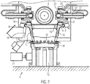
- FIG 1 a roller mill 1 according to an exemplary embodiment of the invention is shown.
- the roller mill 1 has a grinding table 2 and four grinding rollers 3 .
- the grinding table can be designed integrally as a ring or be formed from ring segments.
- the grinding table 2 is driven by a drive 4 about its vertical central axis.
- the grinding roller 3 is mounted in a rocker arm 5 so as to be rotatable about a roller axis of rotation.
- the oscillating lever 5 is mounted in a console 6 so that it can pivot about a bearing axis.
- the console 6 is attached directly to the foundation.
- hydraulic cylinders 7 can be provided, which are connected to the rocker arm 5 at a distance from the bearing axis of the rocker arm. Starting from the foundation, a force can be applied to the rocker arm 5 with the hydraulic cylinder. This can be used to swing the grinding rollers 3 out of engagement with the grinding table 2, or to adjust the normal force between the respective grinding roller 3 and the grinding table 2.
- the particulate bulk material is introduced onto the grinding table 2 so that it is ground between the grinding rollers 3 and the grinding table 2 . Then the ground bulk material is exposed to an air flow through a nozzle ring 8 arranged radially outside of the grinding table 2 . The air flow feeds the ground bulk material to a sifter (not shown), which can lead coarse components back to the grinding table 2 and removes sufficiently fine particles from the roller mill 1 .
- the particulate bulk material is in particular a clay mixture. For the mechanochemical activation of the clay mixture, it is ground at a minimum temperature of 300 °C and a maximum of 1000 °C.
- the roller mill 1 has an air inlet, which forms a hot gas feed line 9, with which the hot gas is introduced into the mill.
- the hot gas flows in particular through the Hot gas supply line 9 and then through the nozzle ring 8 into the interior of the housing 10.
- the housing 10 of the mill is shown in figure 1 shown with large openings.
- the housing is essentially closed and, in particular, is provided with an insulating layer on the outside and/or inside in order to keep heat in the process.
- seals can be provided in the area where the axes of the grinding rollers 3 pass through the housing 10 .
- a sealing air seal can be carried out with hot process gas.
- the drive 4 of the roller mill 1 comprises a drive motor 11 and a drive gear 12.
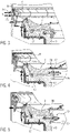
- the grinding table 2 is arranged on a grinding table 13, which is a substantially hollow component with a wall in the circumferential direction, and in the upper area with a flange-like bearing surface 14 for the grinding table 2 is provided.
- Cooling medium openings 15 are provided in the lower area of the grinding bowl 13 .
- an optional 13 in 1 housing not shown, can be provided via the cooling medium to the cooling medium openings 15 .
- cooling ambient air can flow in.
- the cooling medium can be sucked into the grinding bowl 13 through the cooling medium openings 15 in particular due to a negative pressure inside the grinding bowl 13 .
- the cooling medium can be conveyed under pressure, for example by a fan.
- the cooling air can be extracted by an extraction device.
- the grinding bowl 13 has a contact surface 16 , the cooling medium openings 15 being provided as interruptions in the contact surface 16 .
- the grinding table 13 stands with the contact surface 16 on an upper surface of the drive gear 12 .
- the cooling medium openings 15 not only allow cooling medium to enter the interior of the grinding bowl 13, but also that the contact surface between the grinding bowl 13 and the drive gear 12 is reduced, so that only less heat conduction can occur between the grinding bowl 13 and the drive gear 12.
- At least one thermal insulation element 17 is arranged on the outer circumference of the grinding bowl 13 .
- This can in particular be an insulating and heat-resistant layer which is attached to the outside of the circumference of the grinding bowl 13 at least in certain areas.
- a heat shield in the form of a baffle plate 18 can be provided in front of an exit from the hot gas feed line 9 , which redirects the hot gas flowing out of the hot gas feed line 9 to the nozzle ring 8 . The hot gas thus does not impinge directly on the grinding bowl 13 or its thermal insulation element 17 .
- the cooling medium supplied to the interior of the grinding bowl 13 not only cools the grinding bowl 13 from the inside and the top of the drive gear 12, but can also be discharged from the upper area of the grinding bowl 13 and develop a further cooling effect inside the mill.
- openings or at least one local nozzle 19 can be provided in the grinding bowl 13 for this purpose. In this way, for example, the cooling medium can be directed onto the grinding rollers 3 .
- the nozzle 19 rotates in particular with the grinding table 13.
- at least one local nozzle 20 can also be provided in another area of the roller mill, for example in the upper area of the grinding rollers 3, in order to cool them.
- the nozzle 20 remains stationary.
- the nozzle 20 is supplied with a cooling medium line without grinding bowl contact.
- the grinding roller 3 is mounted on a grinding roller axis 21, cooling medium being conveyed through a line 22 to between the bearings 23, 24 of the grinding roller 3.
- Oil can be used as the cooling medium.
- the line 22 supply cooling medium to a position between the inner bearing 23 and the interior of the mill. In this way, the bearing 23 can not only be cooled, but the cooling medium also protects the bearing 23 from the ingress of dust from the inside of the mill. In particular, cooling air can be used as a cooling medium for this purpose.
- the line 22 it is possible to guide the cooling medium along the grinding roller axis 21 in the outer region.
- the bearings 22, 23 can also be cooled by water cooling by means of a rotary feedthrough in the bearing cap and/or separate channels in the bearing bush.
- FIG 3 a heat-optimized mounting of the nozzle ring 8 according to the invention is shown.
- an elastic element 25 with an elastically mounted pin is provided for this purpose, which engages in a recess 26 of the nozzle ring 8 . If the nozzle ring 8 now expands more than the housing 10 due to heating, this can be compensated for by the elastic mounting of the pin 25 .
- the pin can only be displaced in the radial direction of the nozzle ring 8 .
- the preload can be effected by a spring which applies a radially inward force to the pin.
- at least three elastic elements 25 are distributed around the circumference of the nozzle ring 8 with the same pretension and at a uniform spacing. This not only enables the possibility of compensating for different thermal expansions, but also centers the nozzle ring.
- the grinding table 2 is supported by an elastic element 27 with respect to the grinding table 13 .
- the elastic element 27 is, in particular, a pin which can be inserted into a recess by means of an elastic force 28 of the grinding table 2 engages.
- the pin is elastically biased by a spring.
- the pin extends primarily in the radial direction of the grinding table 2.
- the pin engages in the recess 28 of the grinding table 2, directed radially outward.
- an elastic element can engage radially inwards in a recess of the grinding table 2 that is open radially outwards.
- the elastic element 29 has a clamping element which applies an elastic force to a radial side surface 30 of the grinding table 2 .
- the side surface 30 can be inclined with respect to the axial direction of the grinding table 2 in order to also provide a holding force in the axial direction.
- the side face 30 is provided radially on the inside of the grinding table 2 .
- the clamping element and the side surface 31 can also be provided radially on the outside of the grinding table 2 .
- the elastic member 29 is provided at a plurality of positions in the circumferential direction for fixing the grinding table 2, in particular at least three positions.
- the elastic elements 27 or 29 can not only compensate for different thermal expansions between the grinding table 2 and the grinding table 13, but also center the grinding table 2 with respect to the grinding table 13.
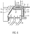
- FIG 6 another embodiment is shown.
- the grinding table 2 designed in one or more parts, is arranged on an upper flange area 31 of the grinding table 13 .
- the cooling line 32 extends essentially in the radial direction of the grinding table 13.
- the cooling line 32 can also be provided through recesses in the lower bearing surface of the grinding table 2 and/or in the surface of the flange area 31, so that the cooling line 32 between the grinding table 2 and the flange area 31 is formed.
- the cooling line 32 thus enables the grinding table 13 to be protected from the high temperatures in the area of the grinding table 2 .
- a coolant space 33 can be provided radially outside of the grinding bowl 13 .
- the coolant space 33 can be delimited in particular by a heat-insulating wall 34 from a space for hot gas that is located further radially on the outside.
- the heat insulating wall 34 can be fixed to the grinding bowl 13 and rotate with it.
- the heat-insulating wall 34 can have a base seal in order to enable a tight connection to a stationary boundary of the coolant space 33 .
- the radially inner delimitation of the coolant space 33 can be formed directly by the grinding bowl 13 .
- the cooling medium in the cooling space can thus cool the grinding bowl 13 from the outside.
- the cooling medium space 33 and the cooling line 32 enable more intensive cooling in the radially outer area of the grinding bowl 13, in particular in the flange area 31, where elevated temperatures can occur. In this way, thermal stresses in the grinding bowl 13 due to temperature differences can be avoided.
- One or more recesses 35 can be provided in the lower region of the grinding table 2 , which is designed in one or more parts, and reduce the heat conduction from the grinding table 2 to the grinding table 13 .
- a thermal insulation element 17 can be provided which fills the recess 35 .
- the grinding table 2 thus has a hollow, thermally insulated support.
- the cooling medium is blown under pressure, for example by a blower, into the cooling air space 33 via a cooling medium feed line 35 .
- the cooling medium flows out of the cooling medium space 33 into the cooling line 32.
- the cooling medium flows out of the cooling line 32 into the hollow interior of the grinding bowl 13 and then through openings 15 in the lower edge region of the grinding bowl 13 back into the cooling space.
- the cooling medium can be sucked into the cooling line 32 under negative pressure.
- the coolant space 33 can be designed to be open, as indicated by the dashed arrows.
- the negative pressure can take place in particular by a forced discharge of cooling medium through a cooling medium discharge line 36 which is connected to the openings 15 .
- a fan arranged in or after the cooling medium discharge line 36 can be provided for this purpose.
- the aforesaid roller mill allows the clay mixture to be subjected to high temperatures and mechanical stress, particularly pressure and shear, at the same time.
- the mechanical load on the clay mixture occurs between two solid surfaces, which, depending on their geometric design and arrangement, move relative to one another.
- the solid surfaces are formed by the grinding roller and the grinding table.
- the aforesaid roll mill is generally operated as an air-swept mill.
- the clay mixture is transported by a carrier gas flow, in particular the hot gas, to a sifter, not shown, in which particles that fall below a certain degree of fineness are removed, while larger particles or conglomerates of particles are returned to the grinding process.
- the clay mixture activated in this way then provides an increased ability of a pozzolanic reaction for later use in comparison with an unactivated clay mixture. This is advantageous when curing cement containing the activated clay mixture as an additive.
- calcium hydroxide and silicon dioxide combine to form calcium silicate hydrates and improve curing compared to other additives, especially non-activated ones.
- one embodiment of the method according to the invention for mechanochemically activating a clay mixture can be carried out with the roller mill described above, in which the clay mixture is ground in the mill 1 at a temperature in the temperature range of at least 300° C. to 1000° C.
- the crystal water present in the layered silicates is expelled by dehydroxylation and the crystal structure of the layered silicates changes, with amorphization taking place in particular.
- an activation energy of more than 300 kilojoules per kilogram, in particular more than 400 kilojoules per kilogram, is necessary for this.
- the method according to the invention is designed in particular for the processing of naturally occurring clay mixtures. These consist of thermally activatable sheet silicates such as kaolinite, illite and mica, as well as various inert components such as quartz and feldspar. Clays with a high phyllosilicate content are advantageous.
- the activability of the clays depends on the mineral phase composition, i.e. on the type of layered silicate, the structure of the layered silicates and lattice defects and disorders in the crystal lattice.
- the clays should be converted into a largely amorphous state by the activation process.
- the activated clay material can be provided as a cement additive or Portland clinker substitute, in which case, for example, a 35% share of the cement can be replaced by a correspondingly activated clay mixture, which means that a total of 50% of carbon dioxide emissions can be avoided.
Description
Die vorliegende Erfindung betrifft ein Verfahren zum mechanochemischen Aktivieren eines Tongemischs und eine diesbezügliche Wälzmühle.The present invention relates to a method for mechanochemically activating a clay mixture and a related roller mill.
Weltweit wird im Bauwesen Zementbeton eingesetzt, welcher das Bindemittel Zement, Wasser und eine Gesteinskörnung umfasst. Aus ökonomischen und ökologischen Gründen können Zementzusatzstoffe zum Einsatz kommen. Ziel ist es dabei, den Klinkeranteil im Zement bzw. Beton zu verringern, um CO2-Emissionen zu reduzieren. Zudem können zusätzliche Rohstoffquellen für die Produktion von Zement erschlossen werden.Cement concrete is used worldwide in construction, which comprises the binder cement, water and aggregate. Cement additives can be used for economic and ecological reasons. The aim is to reduce the clinker content in cement or concrete in order to reduce CO2 emissions. In addition, additional sources of raw materials can be tapped for the production of cement.
Die
Auch in der
Schließlich ist es aus der
Es ist die Aufgabe der vorliegenden Erfindung ein vorteilhaftes Verfahren zum mechanochemischen Aktivieren eines Tongemischs bereitzustellen.It is the object of the present invention to provide an advantageous method for mechanochemically activating a clay mixture.
Die Erfindung stellt ein Verfahren zum mechanochemischen Aktivieren eines Tongemischs bereit, bei dem das Tongemisch in einer Mühle bei einer Temperatur gemahlen wird, wobei die Temperatur in einem Temperaturbereich von 300 °C (Grad Celsius) bis 1000 °C liegt. Insbesondere weist das Tongemisch die vorgenannte Temperatur während des Mahlens auf. Dies bewirkt ein thermomechanisches Aktivieren des Tongemischs. Durch das erfindungsgemäße Verfahren wird insbesondere eine Dehydroxylierung der im Tongemisch enthaltenen Schichtsilikate bewirkt. Schichtsilikate sind vornehmlich aus Silicium-(SiO4-)Tetraeder-Schichten, Aluminium-(AlO6-)Oktaeder-Schichten und/oder Magnesium-(MgO6-)-Oktaeder-Schichten aufgebaut, die OH-Banden bzw. Hydroxyl-Gruppen aufweisen.The invention provides a method of mechanochemically activating a clay mixture comprising grinding the clay mixture in a mill at a temperature, the temperature being in a temperature range of from 300°C (degrees Celsius) to 1000°C. In particular, the clay mixture has the aforesaid temperature during milling. This causes a thermo-mechanical activation of the clay mixture. The method according to the invention brings about, in particular, a dehydroxylation of the phyllosilicates contained in the clay mixture. Phyllosilicates are primarily made up of silicon (SiO 4 ) tetrahedron layers, aluminum (AlO 6 ) octahedron layers and/or magnesium (MgO 6 ) octahedron layers, the OH bands or hydroxyl groups exhibit.
Bei der Dehydroxylierung werden diese OH-Banden bzw. Hydroxyl-Gruppen aus dem Schichtsilikat abgespalten, wodurch Wasser entsteht. Zusätzlich zu diesem chemischen Prozess wird das Wasser durch den Mahldruck beim erfindungsgemäßen Mahlen aus dem Tongemisch herausgedrückt und durch die hohen Temperaturen abgetrennt. Zudem findet eine teilweise Amorphisierung der Kristallstrukturen statt.During dehydroxylation, these OH bands or hydroxyl groups are split off from the phyllosilicate, resulting in the formation of water. In addition to this chemical process, the water is pressed out of the clay mixture by the grinding pressure during grinding according to the invention and separated by the high temperatures. In addition, a partial amorphization of the crystal structures takes place.
Im Ergebnis kommt es also zu einer thermisch unterstützten mechanochemischen Aktivierung des Tongemischs, so dass es beim Einsatz als Zementzusatzstoff oder Zementklinkerersatzstoff in erhöhtem Maße einer puzzolanen Reaktion zugänglich ist. Bei der puzzolanen Reaktion werden insbesondere Calcium-Silikat-Hydrate aus den freigesetzten, reaktiven Silicium-Ionen des aktivierten Tongemischs und dem Calciumhydroxid der Porenlösung des Zements gebildet.The result is a thermally assisted mechanochemical activation of the clay mixture, so that when used as a cement additive or cement clinker substitute, it is more susceptible to a pozzolanic reaction. In the pozzolanic reaction, calcium silicate hydrates in particular are formed from the released, reactive silicon ions of the activated clay mixture and the calcium hydroxide of the pore solution of the cement.
Insbesondere wird das Tongemisch bei einer Temperatur in einem Temperaturbereich von 400 °C bis 1000 °C, weiter insbesondere bei einer Temperatur in einem Temperaturbereich von 450 °C bis 950 °C, vorteilhafterweise bei einer Temperatur in einem Temperaturbereich von 450 °C bis 600°C, weiter vorteilhafterweise bei einer Temperatur in einem Temperaturbereich von 500 °C bis 550°C gemahlen. Da die Partikel beim Mahlen des Tongemischs zerkleinert werden, kann eine größere Oberfläche für den Wärmeübergang von einen Heizmedium, insbesondere Heißgas, auf die Partikel ermöglicht werden. Zudem kann der Wärmeleitweg von der Oberfläche bis in das Innere der Partikel verringert werden. Damit können die Partikel schneller und mit geringerem Energieverbrauch erwärmt werden.In particular, the clay mixture is at a temperature in a temperature range from 400 °C to 1000 °C, more particularly at a temperature in a temperature range from 450 °C to 950 °C, advantageously at a temperature in a temperature range from 450 °C to 600 °C C, further advantageously ground at a temperature in a temperature range from 500°C to 550°C. Since the particles are comminuted when the clay mixture is ground, a larger surface area for heat transfer from a heating medium, in particular hot gas, to the particles can be made possible. In addition, the heat conduction path from the surface to the inside of the particles can be reduced. This allows the particles to be heated faster and with less energy consumption.
Zudem kann durch die größere Oberfläche der Partikel des Tongemischs das bei der mechanochemischen Aktivierung freiwerdende Wassers besser abgeleitet werden.In addition, due to the larger surface of the particles of the clay mixture, the water released during the mechanochemical activation can be drained off better.
Je nach den Bestandteilen des Tongemischs kann das Mahlen in verschiedenen Temperaturbereichen erfolgen. Bei einer Temperatur in einem Temperaturbereich von 550 °C bis 700 °C wird eine vorteilhafte Aktivierung von Kaolinit ermöglicht. Bei einer Temperatur in einem Temperaturbereich von 800 °C bis 900 °C wird eine vorteilhafte Aktivierung von Montmorillonit ermöglicht. Bei einer Temperatur in einem Temperaturbereich von 900 °C bis 1000 °C wird eine vorteilhafte Aktivierung von Illit ermöglicht.Depending on the components of the clay mixture, grinding can take place in different temperature ranges. At a temperature in a temperature range of 550° C. to 700° C., advantageous activation of kaolinite is made possible. At a temperature in a temperature range of 800° C. to 900° C., advantageous activation of montmorillonite is made possible. At a temperature in a temperature range from 900° C. to 1000° C., advantageous activation of illite is made possible.
Insbesondere wird beim Mahlen des Tongemischs ein Mahldruck von größer als 350 kN (Kilo-Newton) pro Quadratmeter vorgesehen, und insbesondere von weniger als 2000 kN pro Quadratmeter. Vorteilhafterweise wird ein Mahldruck beim Mahlen des Tongemischs von 800 kN bis 1000 kN pro Quadratmeter vorgesehen.In particular, when grinding the clay mixture, a grinding pressure of greater than 350 kN (kilo-newtons) per square meter is provided, and in particular less than 2000 kN per square meter. Advantageously, a grinding pressure of 800 kN to 1000 kN per square meter is provided when grinding the clay mixture.
In einer Ausführungsform ist die Mühle eine Vertikalwälzmühle, insbesondere eine Walzenschüsselmühle. Im Mahlbereich kann gezielt der erfindungsgemäße Temperaturbereich vorgesehen werden, insbesondere bei Vertikalwälzmühlen, bei welchen die nachfolgend beschriebenen, für einen Mahlbetrieb bei derartig erhöhten Temperaturen, vorteilhaften Gestaltungen vorgesehen werden können. In anderen Ausführungsformen kann das erfindungsgemäße Verfahren in einer Kugelmühle, Hammermühle, Walzenmühle, insbesondere Gutbettwalzenmühle, oder Rollenmühle erfolgen.In one embodiment, the mill is a vertical roller mill, in particular a vertical roller mill. The temperature range according to the invention can be provided in a targeted manner in the grinding area, in particular in vertical roller mills, in which the configurations described below, which are advantageous for grinding operation at such elevated temperatures, can be provided. In other embodiments, the method according to the invention can be carried out in a ball mill, hammer mill, roller mill, in particular high-pressure roller mill, or roller mill.
Insbesondere besteht das Tongemisch zu wenigstens 25 Massenprozent, vorteilhafterweise zu wenigstens 50 Massenprozent aus thermisch aktivierbaren Schichtsilikaten. Weiter vorteilhaft besteht das Tongemisch zu wenigstens 70 Massenprozent aus thermisch aktivierbaren Schichtsilikaten. In einer Ausführungsform des Verfahrens besteht das Tongemisch zu wenigstens 90 Massenprozent aus thermisch aktivierbaren Schichtsilikaten.In particular, the clay mixture consists of at least 25 percent by mass, advantageously at least 50 percent by mass, of thermally activatable phyllosilicates. Further advantageously, the clay mixture consists of at least 70 percent by mass of thermally activatable phyllosilicates. In one embodiment of the method, the clay mixture consists of at least 90 percent by mass of thermally activatable phyllosilicates.
Insbesondere handelt es sich bei den Schichtsilikaten um Zweischichtsilikate, wie Kaolinit oder die Serpentingruppe, Dreischichtsilikate, wie Glimmer, Illit, Smektit, Montmorillonit, und/oder Vierschichtsilikate, wie die Dichloritgruppe. Schichtsilikate kommen in der Natur meist nicht reinphasig vor, sondern enthalten Begleitminerale wie Quarz und Feldspäte, die für das Aktivieren zuoder abträglich sein können.In particular, the layered silicates are two-layer silicates such as kaolinite or the serpentine group, three-layer silicates such as mica, illite, smectite, montmorillonite, and/or four-layer silicates such as the dichlorite group. In nature, phyllosilicates usually do not occur in the pure phase, but contain accompanying minerals such as quartz and feldspar, which can be beneficial or detrimental to activation.
Kaolinit besitzt eine dioktaedrische Zweischichtstruktur, bestehend aus SiO4-Tetraedern und AlO6-Oktaedern. An den äußeren Oktaederspitzen sitzen Hydroxylgruppen, die zu Sauerstoffatomen der nächsten Tetraeder-Schicht Wasserstoffbrückenbindungen aufbauen. Die freien Tetraederspitzen der SiO4-Schicht verknüpfen zusammen mit OH-Gruppen der Oktaeder-Schicht die Al3+-Kationen der Oktaeder-Schicht und sättigen diese ab. Mit diesen zwei Mechanismen entsteht die Verbindung von jeweils einer Tetraeder-Schicht mit einer Oktaeder-Schicht. Bei der thermisch unterstützten mechanochemischen Aktivierung, vorteilhafterweise zwischen 450 °C bis 600 °C oder zwischen 550 °C bis 700 °C, werden im Rahmen der Dehydroxylierung Hydroxyl-Ionen aus der Oktaeder-Schicht abgespalten und die kristalline Struktur des Kaolinits wird in eine ungeordnete Struktur überführt.Kaolinite has a dioctahedral two-layer structure consisting of SiO 4 tetrahedra and AlO 6 octahedra. At the outer tips of the octahedron are hydroxyl groups that form hydrogen bonds to the oxygen atoms in the next tetrahedron layer. The free tetrahedron tips of the SiO 4 layer combine with the OH groups of the octahedron layer and saturate the Al3 + cations of the octahedron layer. These two mechanisms result in the connection of a tetrahedron layer with an octahedron layer. In the thermally assisted mechanochemical activation, advantageously between 450 °C to 600 °C or between 550 °C to 700 °C, hydroxyl ions are split off from the octahedron layer as part of the dehydroxylation and the crystalline structure of the kaolinite becomes disordered structure transferred.
Illit und Glimmer besitzen eine dioktaedrische, und seltener trioktaedrische, Dreischichtstruktur, welche aus einer AlO6-Oktaeder-Schicht zwischen zwei SiO4-Tetraeder-Schichten besteht. Die Verbindung der Dreischichtpakete erfolgt über K+-Ionen als Zwischenschichtkationen. Bei Illit kann das K+-Ion vorwiegend durch H3O+-Ionen ersetzt sein. Im Gegensatz zu Kaolinit sind die Hydroxylgruppen zwischen den beiden SiO4-Tetraeder-Schichten angeordnet. Dies bedingt auch die deutlich höhere Dehydroxilierungstemperatur für Illit vorteilhafterweise zwischen 900 °C und 1000 °C. Bei Glimmermineralien können verschiedene notwendige Aktivierungstemperaturen vorliegen. Bei Muskovit treten strukturelle Umwandlungen bereits bei 500 °C auf, während bei Paragonit bei 900°C noch keine Aktivierung auftritt.Illite and mica have a dioctahedral, and more rarely trioctahedral, three-layer structure consisting of an AlO 6 octahedral layer between two SiO 4 tetrahedral layers. The three-layer packages are connected via K + ions as interlayer cations. In the case of illite, the K + ion can be predominantly replaced by H 3 O + ions. In contrast to kaolinite, the hydroxyl groups are arranged between the two SiO 4 tetrahedron layers. This also causes the significantly higher dehydroxylation temperature for illite, advantageously between 900°C and 1000°C. Various activation temperatures may be required for mica minerals. In the case of muscovite, structural transformations already occur at 500 °C, while no activation occurs in paragonite at 900 °C.
Montmorillonit ist ein dioktaedrisches Dreischichtsilikat, das in einer Zwischenschicht mit austauschbaren Kationen und Wassermolekülen besetzt ist, und dessen optimale Aktivierungstemperatur zwischen 800 °C und 900 °C liegt.Montmorillonite is a dioctahedral three-layer silicate, which is occupied in an intermediate layer with exchangeable cations and water molecules, and whose optimal activation temperature is between 800 °C and 900 °C.
Als Zementklinkerersatzstoff werden vorteilhafterweise Tongemische, die sich aus quarzhaltigen Tonen mit verschiedenen Anteilen an Schichtsilikaten und Begleitmineralien zusammensetzen, eingesetzt wegen der hohen weltweiten Verfügbarkeit. Vorteilhafterweise besteht das Tongemisch zu wenigstens 90 Massenprozent aus Tonmineralien, die einen hohen SchichtsilikatAnteil aufweisen. Bevorzugt werden Tongemische mit Tonmineralien, die insbesondere zur Kaolinitgruppe, Smektitgruppe oder zur Vermiculitgruppe gehören, oder Mischungen davon.Clay mixtures composed of quartz-containing clays with various proportions of phyllosilicates and accompanying minerals are advantageously used as cement clinker substitutes because of their high worldwide availability. Advantageously, there is Clay mixture of at least 90% by mass of clay minerals with a high proportion of layered silicate. Clay mixtures with clay minerals belonging in particular to the kaolinite group, smectite group or vermiculite group, or mixtures thereof, are preferred.
Insbesondere weist das Tongemisch einen Sulfatgehalt von weniger als 3 Massenprozent auf. Vorteilhafterweise weist das Tongemisch ein Sulfatgehalt von weniger als 2 Massenprozent auf. Beispielsweise kann das Tongemisch 1 Massenprozent an Sulfaten aufweisen. Insbesondere weist das Tongemisch dementsprechend geringe oder keine Anteile von Gips auf.In particular, the clay mixture has a sulfate content of less than 3 percent by mass. Advantageously, the clay mixture has a sulfate content of less than 2 percent by mass. For example, the clay mixture can contain 1% by mass of sulfates. In particular, the clay mixture accordingly has little or no gypsum content.
Insbesondere wird das Tongemisch in der Mühle gemahlen, und die Mühle wird kontinuierlich von Heißgas durchströmt. Nachdem das Heißgas einen nur geringen Feuchtigkeitsanteil aufweist, kann damit das im Tongemisch freiwerdende Wasser effektiv abgeführt werden, wodurch die mechanochemische Aktivierung beschleunigt wird. Das zugeführte Heißgas weist insbesondere eine Temperatur von 300 °C bis 1000 °C auf, vorteilhafterweise eine Temperatur zwischen 400 °C und 1000 °C, weiter vorteilhafterweise eine Temperatur zwischen 500 °C und 750 °C.In particular, the clay mixture is ground in the mill and hot gas flows continuously through the mill. Since the hot gas has only a low moisture content, the water released in the clay mixture can be effectively removed, which accelerates the mechanochemical activation. The supplied hot gas has in particular a temperature of 300°C to 1000°C, advantageously a temperature between 400°C and 1000°C, further advantageously a temperature between 500°C and 750°C.
In einer Ausführungsform des Verfahrens wird der Mühle zusätzlich Kühlmedium, insbesondere Kühlluft oder Wasser bzw. Wasserdampf, zugeführt. Somit kann eine Erhitzung des Tongemischs ermöglicht werden, und gleichzeitig können temperaturkritische Bauteile der Mühle durch das Kühlmedium gekühlt werden. Das Kühlmedium kann insbesondere direkt auf zu kühlende Bauteile der Mühle außerhalb des Mahlraums zugeführt werden. Insbesondere kann eine Zementersatzmischung, die wenigstens 6 Massenprozent und maximal 90 Massenprozent eines Bindemittels umfasst, durch das vorangehend beschriebene erfindungsgemäße Verfahren hergestellt werden.In one embodiment of the method, cooling medium, in particular cooling air or water or steam, is additionally supplied to the mill. The clay mixture can thus be heated, and at the same time temperature-critical components of the mill can be cooled by the cooling medium. In particular, the cooling medium can be fed directly to components of the mill that are to be cooled outside of the grinding chamber. In particular, a cement substitute mixture comprising at least 6 percent by mass and at most 90 percent by mass of a binder can be produced by the method according to the invention described above.
Insbesondere kann die Zementmischung wenigstens 6 Massenprozent eines Zementzusatzstoffes umfassen, der durch das vorangehend beschriebene erfindungsgemäße Verfahren hergestellt wurde. Insbesondere weist die Zementmischung höchstens 90 Massenprozent dieses Zementzusatzstoffes auf. Weiter insbesondere weist die Zementmischung höchstens 50 Massenprozent dieses Zementzusatzstoffes auf. Vorteilhafterweise weist die Zementmischung höchstens 35 Massenprozent dieses Zementzusatzstoffes auf. In einer Ausführungsform weist die Zementmischung höchstens 20 Massenprozent des Zementzusatzstoffes auf. In einer anderen Ausführungsform weist die Zementmischung wenigstens 21 Massenprozent des Zementzusatzstoffes auf.In particular, the cement mixture may comprise at least 6% by mass of a cement additive produced by the method according to the invention described above. In particular, the cement mixture contains at most 90% by mass of this cement additive. More particularly, the cement mixture has at most 50 percent by mass of this cement additive. Advantageously, the cement mixture contains at most 35% by mass of this cement additive. In one embodiment, the cement mixture has at most 20% by mass of the cement additive. In another embodiment, the cement mixture comprises at least 21% by mass of the cement additive.
Das der Mühle zugeführte Tongemisch ist insbesondere in Form eines partikelförmigen Schüttguts. Tone bestehen nach geologischer Nomenklatur insbesondere aus Mineralpartikeln kleiner 20 µm und einem silicatischen Tonmineralanteil mit Partikelgrößen kleiner 2 µm. Wenigstens 50 % der Partikel des der Mühle zugeführten Tongemischs haben insbesondere eine Größe zwischen 0,2 Mikrometer und 9 Mikrometer. Diese Partikel können zu Konglomeraten verbunden sein. Das der Mühle zugeführte Tongemisch hat insbesondere eine BET-Oberfläche zwischen 5 und 42 Quadratmeter pro Gramm.The clay mixture fed to the mill is in particular in the form of a particulate bulk material. According to geological nomenclature, clay consists primarily of mineral particles smaller than 20 µm and a silicate clay mineral content with particle sizes smaller than 2 µm. In particular, at least 50% of the particles of the clay mixture fed to the mill have a size between 0.2 microns and 9 microns. These particles can be connected to form conglomerates. In particular, the mixed clay fed to the mill has a BET surface area of between 5 and 42 square meters per gram.
Das Tongemisch weist vor dem Mahlen vorteilhafterweise Partikelgrößen von 2 Mikrometer bis 5 Mikrometer auf. Das erfindungsgemäße Mahlen dient somit insbesondere nicht vornehmlich dem Zerkleinern, sondern der mechanischen Unterstützung der chemischen Reaktion der Dehydroxylierung und weiterhin insbesondere der Amorphisierung der kristallinen Strukturen. Insbesondere können die Schichtsilikate des Tongemischs vor der erfindungsgemäßen Aktivierung ca. 13 bis 19 Massenprozent Kristallwasser aufweisen. Durch das erfindungsgemäße Mahlen kann insbesondere bereits durch eine geringere Zufuhr von Wärmeenergie eine Aktivierung des Tongemischs erfolgen, als bei der üblichen Erhitzung ohne Mahlvorgang wie im Stand der Technik gelehrt. Insbesondere kann durch den Einsatz eines während des Mahlens über das Tongemisch strömenden Heißgases eine effiziente Erwärmung des Tongemischs und schnelle Abfuhr von aus dem Tongemisch freiwerdendem Wasser erfolgen, was die Effizienz der Aktivierung erhöht.Before milling, the clay mixture advantageously has particle sizes of 2 microns to 5 microns. The grinding according to the invention is therefore not primarily used for comminution, but rather to mechanically support the chemical reaction of dehydroxylation and furthermore, in particular, the amorphization of the crystalline structures. In particular, the phyllosilicates of the clay mixture can have about 13 to 19 percent by mass of water of crystallization before activation according to the invention. As a result of the grinding according to the invention, activation of the clay mixture can take place in particular with a lower supply of thermal energy than in the case of conventional heating without grinding as taught in the prior art. In particular, by using a hot gas flowing over the clay mixture during grinding, the clay mixture can be heated efficiently and water released from the clay mixture can be removed quickly, which increases the efficiency of the activation.
Der Betrieb einer Wälzmühle bei der vorgenannten hohen Temperatur zwischen 300 °C und 1000 °C zur Durchführung des erfindungsgemäßen Verfahrens führt zu einer hohen thermischen Beanspruchung der Mühle.The operation of a roller mill at the aforementioned high temperature of between 300° C. and 1000° C. for carrying out the method according to the invention leads to high thermal stress on the mill.
Die vorliegende Erfindung stellt weiterhin eine Wälzmühle, insbesondere zum thermisch unterstützen mechanochemischen Aktivieren eines Tongemischs, bereit, wobei die Wälzmühle einen Antrieb, eine Mahlschüssel, einen Mahlteller und Mahlwalzen umfasst. Die Mahlschüssel ist auf dem Antrieb angeordnet, wobei der Antrieb ausgelegt ist, die Mahlschüssel anzutreiben, sodass die Mahlwalzen auf dem Mahlteller abrollen. Erfindungsgemäß sind Öffnungen im Randbereich der Mahlschüssel vorgesehen, um den Durchfluss von Kühlmedium zu ermöglichen. Vorteilhafterweise sind die Öffnungen im unteren Bereich der Mahlschüssel vorgesehen, um den Eintritt von Kühlmedium in das Innere der Mahlschüssel zu ermöglichen. In einer anderen vorteilhaften Ausführungsform können die Öffnungen im oberen Bereich der Mahlschüssel vorgesehen sein, insbesondere in einem Bereich unter der Auflagefläche für die Mahlteller. Damit kann die thermische Beanspruchung der Mühle reduziert werden. Das Kühlmedium wird insbesondere durch die Mahlschüssel geführt, um besonders hitzegefährdete Bereiche zu kühlen, vornehmlich Bereiche mit geringen Materialstärken, empfindlichen Bauteilen oder Bereiche, die einer hohen Wärmeleistung ausgesetzt sind. Vorteilhafterweise wird dadurch eine Vergleichmäßigung der Temperaturniveaus erreicht.The present invention further provides a roller mill, in particular for the thermally assisted mechanochemical activation of a clay mixture, the roller mill comprising a drive, a grinding table, a grinding table and grinding rollers. The grinding table is arranged on the drive, the drive being designed to drive the grinding table so that the grinding rollers roll on the grinding table. According to the invention, openings are provided in the edge area of the grinding table in order to allow the cooling medium to flow through. The openings are advantageously provided in the lower region of the grinding bowl in order to allow cooling medium to enter the interior of the grinding bowl. In another advantageous embodiment, the openings can be provided in the upper area of the grinding table, in particular in an area below the bearing surface for the grinding table. The thermal stress on the mill can thus be reduced. The cooling medium is guided in particular through the grinding table in order to cool areas that are particularly at risk of heat, primarily areas with low material thicknesses, sensitive components or areas that are exposed to high thermal output. This advantageously achieves an equalization of the temperature levels.
In einer Ausführungsform ist die Wälzmühle eine Vertikalwälzmühle, insbesondere eine Walzenschüsselmühle. Die Wälzmühle weist insbesondere einen Sichter auf, der lediglich Partikel, die einen gewissen Feinheitsgrad erreicht haben, aus der Mühle auslässt. Zu grobe Partikel werden einem weiteren Mahlvorgang zugeführt.In one embodiment, the roller mill is a vertical roller mill, in particular a vertical roller mill. In particular, the roller mill has a sifter that only leaves particles that have reached a certain degree of fineness out of the mill. Particles that are too coarse are fed into another grinding process.
Der Kühlmediumeintritt ermöglicht, dass die Mahlschüssel insbesondere in ihrem unteren Bereich gezielt gekühlt wird. Dadurch kann die Wärmeübertragung in den darunter angeordneten Antrieb reduziert werden. Insbesondere umfasst der Antrieb einen Antriebsmotor und ein Getriebe. Die Mahlschüssel ist vorteilhafterweise auf einem Getriebeflansch angeordnet. Durch die Öffnungen kann nicht nur Kühlmedium in das Innere der Mahlschüssel eingebracht werden, um dort eine vorteilhafte Kühlung zu ermöglichen, sondern ein besonderer Kühleffekt tritt im Bereich der Öffnungen auf. Vorteilhafterweise sind mehrere Öffnungen entlang der Umfangsrichtung vorgesehen, sodass vorteilhafterweise ein Umfangsbereich mit einer erhöhten Kühlwirkung in der Mahlschüssel vorgesehen wird, so dass eine Wärmeleitung durch diesen Bereich hin zum Antrieb reduziert wird.The cooling medium inlet enables the grinding table to be cooled in a targeted manner, particularly in its lower area. As a result, the heat transfer into the drive arranged underneath can be reduced. In particular, the drive includes a drive motor and a gear. The grinding bowl is advantageously arranged on a gear flange. Not only can cooling medium be introduced into the interior of the grinding bowl through the openings in order to enable advantageous cooling there, but a special cooling effect also occurs in the area of the openings. Advantageously, several openings are provided along the circumferential direction, so that a circumferential area with an increased cooling effect is advantageously provided in the grinding bowl, so that heat conduction through this area to the drive is reduced.
In einer vorteilhaften Ausführungsform weist die Mahlschüssel eine Aufstandsfläche auf, mit der die Mahlschüssel auf dem Antrieb aufsteht, wobei die Öffnungen als Ausschnitte in der Aufstandsfläche der Mahlschüssel vorgesehen sind. Die Öffnungen sind also zur Aufstandsfläche offen ausgeführt. Damit kann die Wärmeleitfläche zwischen der Mahlschüssel und dem Antrieb reduziert werden. Zusätzlich zur gezielten Kühlwirkung kann somit die Wärmeleitung zwischen Mahlschüssel und Antrieb verringert werden, so dass trotz der hohen Temperaturen im Inneren der Wälzmühle nur ein geringer Wärmebertrag auf deren Antrieb stattfindet. Zudem wird dadurch auch gleichzeitig ermöglicht, Kühlmedium direkt auf den Getriebeabtriebsflansch zu leiten, und damit diesen gezielt zu kühlen. Somit findet in diesem Bereich Kühlung durch erzwungene Konvektion statt, und die Konduktion von Wärme von der Mahlschüssel in den Antrieb, und insbesondere in dessen Getriebe, wird reduziert. Insbesondere sind die Öffnungen als gleichmäßig beabstandete, arkadenförmige Öffnungen in der unteren Aufstandsfläche der Mahlschüssel vorgesehen.In an advantageous embodiment, the grinding table has a contact surface with which the grinding table stands on the drive, the openings being provided as cutouts in the contact surface of the grinding table. The openings are therefore designed to be open to the contact area. The heat conducting surface between the grinding table and the drive can thus be reduced. In addition to the targeted cooling effect, the heat conduction between the grinding table and the drive can thus be reduced, so that despite the high temperatures inside the roller mill, only a small amount of heat is transferred to its drive. In addition, this also makes it possible at the same time to conduct cooling medium directly to the transmission output flange and thus to cool it in a targeted manner. Thus, cooling by forced convection takes place in this area and the conduction of heat from the grinding table into the drive, and in particular into its gearing, is reduced. In particular, the openings are provided as evenly spaced, arcade-shaped openings in the lower contact surface of the grinding bowl.
Insbesondere wird der obere Bereich des radial außenliegenden Kragens der Mahlschüssel mit Heißgas bestrichen. Damit wird die Erwärmung der Mahlschüssel ist auf ein das kleines Maß beschränkt.In particular, the upper area of the radially outer collar of the grinding bowl is coated with hot gas. This limits the heating of the grinding bowl to a small extent.
Des Weiteren wird über den einen Verschleißbereich bildenden Mahlteller im oberen Bereich der Mahlschüssel Wärme eingetragen. Um diesen Wärmeeintrag zu reduzieren, kann das wenigstens eine oder mehrere Verschleißteile, die den Mahlteller bilden, nur teilweise, insbesondere über stegförmige Bereiche aufliegen, um den Wärmeübergang durch Wärmeleitung zu reduzieren. Die nicht aufliegenden Bereiche können mit einer Wärmedämmung, vorzugsweise aus Mineralwolle, versehen oder ausgefüllt sein, um auch dort den Wärmeübergang zu reduzieren.Furthermore, heat is introduced via the grinding table, which forms a wear area, in the upper area of the grinding table. In order to reduce this heat input, the at least one or more wearing parts that form the grinding table can only partially, in particular rest on ridge-shaped areas to reduce the heat transfer through thermal conduction. The non-supporting areas can be provided or filled with thermal insulation, preferably made of mineral wool, in order to reduce the heat transfer there as well.
In einer vorteilhaften Ausführungsform weist die Mahlschüssel eine Kühlung auf, welche zu einer Vergleichmäßigung der Temperatur der verschiedenen Bereiche der Mahlschüssel führt, insbesondere der Bereiche, welche durch die Mahlkraft und/oder durch Wärmespannungen mechanisch hoch beansprucht sind. Zudem kann die Bauteiltemperatur in einem Bereich gehalten werden, bei welchem das Bauteilmaterial ausreichend Festigkeit und Gefügebeständigkeit aufweist.In an advantageous embodiment, the grinding table has cooling, which leads to an equalization of the temperature of the various areas of the grinding table, in particular the areas that are mechanically highly stressed by the grinding force and/or by thermal stresses. In addition, the component temperature can be kept in a range in which the component material has sufficient strength and structural stability.
Insbesondere kann die Mahlschüssel mit wenigstens einem Kühlkanal oder mehreren Kühlkanälen versehen sein, welche ein Kühlmedium gezielt in die beanspruchten Bereiche führen. Die Kühlkanäle können insbesondere in den weniger beanspruchten Bereichen angeordnet werden, und werden mit einem Kühlmedium durchströmt, das in die beanspruchten Bereiche geleitet wird. Dieses Kühlmedium kann gasförmig oder flüssig sein und entweder im Druck- oder Unterdruckbetrieb gefördert werden.In particular, the grinding bowl can be provided with at least one cooling channel or several cooling channels, which guide a cooling medium in a targeted manner into the stressed areas. The cooling ducts can be arranged in particular in the less stressed areas, and a cooling medium flows through them, which is directed into the stressed areas. This cooling medium can be gaseous or liquid and can be pumped either under pressure or under pressure.
Das Kühlmedium kann im Außenbereich der Mahlschüssel über eine Zuführleitung oder direkt aus der Umgebungsluft der Mühle zugeführt werden.The cooling medium can be fed to the outside of the grinding table via a feed line or directly from the ambient air of the mill.
Vorteilhafterweise wird das Kühlmedium im zu kühlenden Bereich gleichmäßig ringförmig verteilt.Advantageously, the cooling medium is evenly distributed in a ring shape in the area to be cooled.
Das Kühlmedium durchströmt vorteilhafterweise einen ringförmigen Bereich zwischen einem unterhalb des Mahlraums angeordneten Heißgasraum und einem unteren zylindrischen oder kegeligen Teil der Mahlschüssel.The cooling medium advantageously flows through an annular area between a hot gas space arranged below the grinding space and a lower cylindrical or conical part of the grinding bowl.
Vorteilhafterweise ist der dem Heißgasraum zugewandte Teil des Kühlkanals mit einer Wärmedämmung versehen, um dort nur geringe Wärmemengen zu übertragen, sei es durch Konvektion auf das Kühlmedium oder durch Wärmestrahlung der heißen Wand.Advantageously, the part of the cooling channel facing the hot gas space is provided with thermal insulation in order to transfer only small amounts of heat there, whether by convection to the cooling medium or by thermal radiation from the hot wall.
Besonders vorteilhaft ist es, wenn das Kühlmedium in einen den Mahlteller bildenden plattenförmigen oberen Teil der Mahlschüssel am äußeren Rand eintritt und im inneren Bereich austritt. Damit wird der üblicherweise heißere Teil des Mahltellers besser gekühlt als der typischerweise kühlere radial innenliegende Teil. Die radialen Temperaturunterschiede in der Mahlschüssel werden damit reduziert, vorteilhafterweise im Wesentlichen ausgeglichen. Insgesamt wird damit die Temperatur abgesenkt, so dass die Beanspruchung durch Wärmespannungen reduziert wird und auch mögliche Gefügeprobleme im Mahlschüsselwerkstoff vermieden werden.It is particularly advantageous if the cooling medium enters a plate-shaped upper part of the grinding table forming the grinding table at the outer edge and exits in the inner area. The usually hotter part of the grinding table is thus better cooled than the typically cooler radially inner part. The radial temperature differences in the grinding table are thus reduced, advantageously essentially balanced out. Overall, the temperature is lowered so that the stress caused by thermal stresses is reduced and possible structural problems in the material of the grinding bowl are also avoided.
Eine weitere Wirkung ist die höhere Festigkeit des Werkstoffs bei den geringeren Temperaturen.Another effect is the higher strength of the material at the lower temperatures.
Das erwärmte Kühlmedium kann innerhalb des von der Mahlschüssel umschlossenen Raums nach unten gefördert werden, und im unteren Bereich durch eine oder mehrere Öffnungen wieder austreten, insbesondere aus einem Ringkanal um den unteren Bereich der Mühle. Diese Öffnungen in der Mahlschüsselhalswand sowie die innere Wandung des Mahlschüsselhalses werden vorteilhafterweise thermisch isoliert, um keine thermischen Ungleichmäßigkeiten im Mahlschüsselhals zu verursachen, sowie um die Wärmelast für den Antrieb zu reduzieren.The heated cooling medium can be conveyed downwards within the space enclosed by the grinding bowl and exit again in the lower area through one or more openings, in particular from an annular channel around the lower area of the mill. These openings in the grinding table neck wall as well as the inner wall of the grinding table neck are advantageously thermally insulated in order not to cause thermal irregularities in the grinding table neck and to reduce the heat load on the drive.
Das Kühlmedium wird dann nach außerhalb der Mühle abgefördert und gegebenenfalls weiterer Verwendung zugeführt, beispielsweise einer Wärmerückgewinnung oder insbesondere im Fall von Umgebungsluft als Prozessgas einem Brenner eines Heißgaserzeugers zugeführt.The cooling medium is then conveyed to the outside of the mill and, if necessary, put to further use, for example to heat recovery or, in particular in the case of ambient air, to a burner of a hot gas generator as process gas.
Insbesondere umfasst die Wälzmühle eine Mahlschüssel, auf deren äußerem Umfang wenigstens bereichsweise ein Wärmeisolationselement vorgesehen ist. Insbesondere kann das Wärmeisolationselement eine Wärmeisolierungsbeschichtung außen auf der Mahlschüssel sein. Alternativ oder zusätzlich kann das Wärmeisolationselement eine außen auf der Mahlschüssel aufgebrachte Wärmeschutzplatte sein. Insbesondere wird die wenigstens eine Wärmeschutzplatte von außen auf die Mahlschüssel aufgeschraubt. In einer Ausführungsform der Wälzmühle wird Heißgas außen an der Mahlschüssel vorbei in den Mahlraum eingeblasen. Das wenigstens eine Wärmeisolationselement verhindert somit eine übermäßige Erwärmung der Mahlschüssel, und damit des Antriebs. Insbesondere ist das wenigstens eine Wärmeisolationselement überwiegend in der oberen Hälfte der Mahlschüssel vorgesehen. Insbesondere ist ein unterer Bereich der Mahlschüssel frei von Wärmeisolationselementen.In particular, the roller mill comprises a grinding table, on the outer circumference of which a thermal insulation element is provided at least in certain areas. In particular, the thermal insulation element can be a thermal insulation coating on the outside of the grinding bowl. Alternatively or additionally, the heat insulation element can be a heat protection plate applied to the outside of the grinding bowl. In particular, the at least one heat protection plate is screwed onto the grinding bowl from the outside. In one embodiment of the roller mill, hot gas is blown past the outside of the grinding table into the grinding chamber. The at least one thermal insulation element thus prevents excessive heating of the grinding bowl and thus of the drive. In particular, the at least one heat insulation element is provided predominantly in the upper half of the grinding bowl. In particular, a lower area of the grinding table is free of thermal insulation elements.
Insbesondere ist wenigstens eine lokale Düse zum Zuführen von Kühlmedium im Innenraum der Wälzmühle vorgesehen. Die lokale Düse ermöglicht, dass besonders erhitzte Bereiche oder besonders hitzeempfindliche Bereiche lokal gekühlt werden können. Bei dem Kühlmedium kann es sich insbesondere um Kühlluft handeln. In anderen Ausführungsformen ist es aber auch möglich Wasser als Kühlmedium zu verwenden, um sich die Verdampfungsenthalpie zur Erzeugung von zusätzlicher Kühlleistung zu Nutze zu machen. Dabei erfolgt vorteilhafterweise eine Einbringung von Wasser möglichst nur so, dass die Feuchtigkeit im Bereich des Mahlguts nicht erhöht wird.In particular, at least one local nozzle for supplying cooling medium is provided in the interior of the roller mill. The local nozzle enables particularly heated areas or particularly heat-sensitive areas to be cooled locally. The cooling medium can in particular be cooling air. In other embodiments, however, it is also possible to use water as the cooling medium in order to utilize the enthalpy of vaporization to generate additional cooling capacity. Advantageously, water is only introduced in such a way that the moisture in the area of the ground material is not increased.
Insbesondere ist lokal wenigstens eine Kühlleitung vorgesehen, die von einem Kühlmittel durchflossen wird. Insbesondere wird das Kühlmittel durch die wenigstens eine Kühlleitung gepumpt.In particular, at least one cooling line is provided locally, through which a coolant flows. In particular, the coolant is pumped through the at least one cooling line.
Durch die lokale Düse kann eine Schleierkühlung oder Filmkühlung bewirkt werden. Alternativ oder zusätzlich ist es möglich eine Prallkühlung vorzusehen, wobei das Kühlmedium ein direktes Auftreffen von heißen Fluiden auf das zu kühlende Bauteil verhindert. In einer Ausführungsform kann lediglich ein Teilstrom des Kühlmediums verwendet werden, beispielweise erzeugt durch einen engen Dichtspalt mit Freistrahlwirkung. Dafür kann eine Druckerhöhung im Kühlmedium auf wenigstens 2 bar, vorteilhafterweise auf 4 bar bis 8 bar vorteilhaft erfolgen. Die Kühldruckluft kann durch eine separate Kühlstromleitung an eine Mahlschüssel- und/oder Walzendichtung herangeführt werden.Veil cooling or film cooling can be effected by the local nozzle. Alternatively or additionally, it is possible to provide impingement cooling, with the cooling medium preventing hot fluids from directly impinging on the component to be cooled. In one embodiment only a partial flow of the cooling medium can be used, for example generated by a narrow sealing gap with free jet effect. For this purpose, the pressure in the cooling medium can be increased to at least 2 bar, advantageously to 4 bar to 8 bar. The cooling compressed air can be fed to a grinding table and/or roller seal through a separate cooling flow line.
Insbesondere ist wenigstens ein Hitzeschild, insbesondere in Form eines Hitzeschutzblechs, vor wenigstens einem Heißgasaustritt vorgesehen.In particular, at least one heat shield, in particular in the form of a heat shield, is provided in front of at least one hot gas outlet.
Durch den Hitzeschild kann ermöglicht werden, dass das in die Mühle einströmende Heißgas verteilt wird, und eine lokale Erhitzung reduziert wird. Der Hitzeschild ist vorteilhafterweise um den ganzen Umfang des Heißgasraums vorgesehen. Der Hitzeschild kann den Heißgasraum von einem Raum für Kühlmedium abgrenzen. Der Hitzeschild kann ein Wärmeisolationselement aufweisen oder aus diesem bestehen.The heat shield can allow the hot gas flowing into the mill to be distributed and reduce local heating. The heat shield is advantageously provided around the entire circumference of the hot gas space. The heat shield can delimit the hot gas space from a space for cooling medium. The heat shield can have or consist of a thermal insulation element.
Insbesondere ist die Mahlwalze auf einer Mahlwalzenachse drehbar gelagert, und Kühlmedium wird durch die oder entlang der Mahlwalzenachse zugeführt. Zusätzlich zu einer lokalen Kühlung der gegebenenfalls wärmeempfindlichen Mahlwalzenlagerungen, verhindert die Kühlmediumzufuhr, dass durch das Mahlen erzeugter Staub die Mahlwalzenlagerung verunreinigt. Insbesondere ist wenigstens eine Kühlmediumöffnung axial in Richtung des Mühleninnerens vor der Walzenabdichtung angeordnet. Damit kann verhindert werden, dass Staub zu der Mahlwalzenlagerung gelangt. Alternativ oder zusätzlich kann wenigstens eine Kühlmediumöffnung zwischen voneinander axial beabstandeten Mahlwalzenlagern angeordnet sein. Damit wird im vorteilhafterweise wenigstes teilabgedichteten Lagerbereich ein höherer Druck sowie ein Luftfluss aus dem Lagerbereich heraus erzeugt. Dadurch wird weitergehend verhindert, dass Staub in die Mahlwalzenlagerungen eindringt. Alternativ oder zusätzlich können die Lager über eine Ölkühlung gekühlt werden.In particular, the grinding roller is rotatably mounted on a grinding roller axis, and cooling medium is supplied through or along the grinding roller axis. In addition to local cooling of the grinding roller bearings, which may be heat-sensitive, the supply of cooling medium prevents dust generated by the grinding from contaminating the grinding roller bearings. In particular, at least one cooling medium opening is arranged axially in the direction of the interior of the mill in front of the roller seal. This can prevent dust from reaching the grinding roller bearing. Alternatively or additionally, at least one cooling medium opening can be arranged between grinding roller bearings that are axially spaced apart from one another. A higher pressure and a flow of air out of the bearing area are thus generated in the advantageously at least partially sealed bearing area. This further prevents dust from penetrating into the grinding roller bearings. Alternatively or additionally, the bearings can be cooled using oil cooling.
Die Mahlschüssel und der Mahlteller können integral ausgeführt sein. Alternativ kann der Mahlteller auch als separates Bauteil mit der Mahlschüssel verbunden werden.The grinding table and the grinding table can be designed integrally. Alternatively, the grinding table can also be connected to the grinding table as a separate component.
Insbesondere wird der Mahlteller durch ein elastisches Element auf der Mahlschüssel befestigt, wobei das elastische Element ausgelegt ist, unterschiedliche Wärmeausdehnungen zwischen dem Mahlteller und der Mahlschüssel auszugleichen. Insbesondere umfasst das elastische Element einen elastisch gelagerten Stift oder ein elastisch gelagertes Klemmelement. Nachdem der Mahlteller und die Mahlschüssel beispielsweise aufgrund von unterschiedlichen Festigkeitsanforderungen gegebenenfalls aus unterschiedlichen Materialien gefertigt sind, kann es zu unterschiedlichen Wärmeausdehnungen kommen, die zu mechanischen Belastungen führen könnten. Dies wird mit einer derartigen Gestaltung ausgeglichen.In particular, the grinding table is attached to the grinding table by an elastic element, the elastic element being designed to compensate for different thermal expansions between the grinding table and the grinding table. In particular, the elastic element comprises an elastically mounted pin or an elastically mounted clamping element. After the grinding table and the grinding bowl are made from different materials, for example due to different strength requirements, different thermal expansions can occur, which could lead to mechanical stresses. This is compensated for with such a design.
Die Wälzmühle kann einen Düsenring umfassen, der sich radial außerhalb des Mahltellers erstreckt, wobei der Düsenring durch ein elastisches Element am Mühlengehäuse befestigt ist, wobei das elastische Element ausgelegt ist, unterschiedliche Wärmeausdehnungen zwischen dem Düsenring und dem Mühlengehäuse auszugleichen. Insbesondere umfasst das elastische Element einen elastisch gelagerten Stift oder ein elastisch gelagertes Klemmelement. Nachdem der Mahlteller und der Düsenring, beispielsweise aufgrund von unterschiedlichen Festigkeitsanforderungen, gegebenenfalls aus unterschiedlichen Materialien gefertigt sind, kann es zu unterschiedlichen Wärmeausdehnungen kommen, die zu mechanischen Belastungen führen könnten. Dies wird mit einer derartigen Gestaltung ausgeglichen.The roller mill may include a nozzle ring that extends radially outside of the grinding table, the nozzle ring being attached to the mill housing by an elastic element, the elastic element being designed to compensate for different thermal expansions between the nozzle ring and the mill housing. In particular, the elastic element comprises an elastically mounted pin or an elastically mounted clamping element. After the grinding table and the nozzle ring are made from different materials, for example due to different strength requirements, different thermal expansions can occur, which could lead to mechanical stresses. This is compensated for with such a design.
Das Mühlengehäuse kann von außen und/oder innen isoliert sein, um Wärme im Prozess zu halten. Eine Isolierung innen im Mühlengehäuse ist vorteilhafterweise als hitzebeständige Panzerung ausgeführt. Dies ermöglich dann aber auch einen Schutz des Gehäusewerkstoffs vor Hitze. Hier kann auch eine Ausmauerung zum Einsatz kommen. Insbesondere kann eine Panzerung innen am Mühlengehäuse vorgesehen sein, und eine Isolierung außen am Mühlengehäuse vorgesehen sein. Alternativ kann eine Isolierung innen am Mühlengehäuse vorgesehen sein, und eine Panzerung innen an der Isolierung vorgesehen sein.The mill housing can be insulated from the outside and/or inside to keep heat in the process. An insulation inside the mill housing is advantageously designed as heat-resistant armouring. However, this also enables the housing material to be protected from heat. A lining can also be used here. In particular, armor can be provided on the inside of the mill housing and insulation can be provided on the outside of the mill housing. Alternatively, insulation can be provided on the inside of the mill housing, and armor can be provided on the inside of the insulation.
In der Wälzmühle können Gleitringdichtungen vorgesehen sein. Dies ermöglicht, dass die Verwendung von hitzeempfindlichen Elastomeren vermieden werden kann.Mechanical seals can be provided in the roller mill. This allows the use of heat sensitive elastomers to be avoided.
In der Wälzmühle können insbesondere im Bereich von Gleitflächen und Lagern Keramikwerkstoffe eingesetzt werden.Ceramic materials can be used in the roller mill, particularly in the area of sliding surfaces and bearings.
Insbesondere ist die Wälzmühle so ausgelegt, dass Heißgas einer ersten Temperatur in das Mühleninnere zugeführt wird, und zusätzlich lokal Heißgas im Mühleninneren einer zweiten Temperatur zugeführt wird, wobei die zweite Temperatur höher als die erste Temperatur ist. Insbesondere besteht ein Temperaturunterschied zwischen der ersten Temperatur und der zweiten Temperatur von wenigstens 100 °C. Dies ermöglicht insbesondere, die erforderliche Temperatur stufenweise zu erreichen und dabei lokale Temperaturmaxima zu vermeiden oder zu reduzieren, die absolute Temperatur gering zu halten und dennoch lokal, insbesondere im Mahlbereich, die gewünschte hohe Temperatur zu erreichen. Zudem kann damit die notwendige Temperatur im Mahlbereich konstant gehalten werden. Im Mahlbereich findet ein hoher Umsatz des Tongemischs statt, das zunächst auf die gewünschte Temperatur gebracht werden muss und dem Heißgas Wärme für die Aktivierungsenergie des Tongemischs entnimmt. Die Temperatur wird vorteilhafterweise auf einem hohen Wert gehalten werden, bis das abgespaltene Wasser aus dem Tongemisch diffundiert ist. Dabei kann das Heißgas wenigstens teilweise in einem inneren Umlauf in der Mühle gehalten werden. Jedoch sollte ausreichend Heißgas aus der Mühle ausgeführt werden, um das abgespaltene Wasser aus der Müle auszutragen. Insbesondere kann ein Nachbrenner im Bereich des Düsenrings vorgesehen werden, um die Temperatur des Heißgases vor dem Sichter hoch zu halten.In particular, the roller mill is designed such that hot gas at a first temperature is fed into the interior of the mill, and hot gas at a second temperature is additionally fed in locally in the interior of the mill, the second temperature being higher than the first temperature. In particular, there is a temperature difference between the first temperature and the second temperature of at least 100°C. In particular, this makes it possible to achieve the required temperature in stages while avoiding or reducing local maximum temperatures, keeping the absolute temperature low and nevertheless achieving the desired high temperature locally, particularly in the grinding area. In addition, the necessary temperature in the grinding area can be kept constant. In the grinding area, there is a high conversion of the clay mixture, which first has to be brought to the desired temperature and takes heat from the hot gas for the activation energy of the clay mixture. The temperature will advantageously be maintained at a high level until the water split off has diffused out of the clay mixture. The hot gas can be kept at least partially in an internal circuit in the mill. However, sufficient hot gas should be discharged from the mill to discharge the separated water from the mill. In particular, an afterburner in the Area of the nozzle ring are provided to keep the temperature of the hot gas high in front of the classifier.
Insbesondere ist das Gehäuse der Wälzmühle segmentiert und mit Dehnfugen ausgestaltet. Die Abstützung des Sichters kann separat vom Gehäuse ausgeführt sein. Damit können unterschiedliche Wärmeausdehnungen kompensiert werden.In particular, the housing of the roller mill is segmented and designed with expansion joints. The separator can be supported separately from the housing. This allows different thermal expansions to be compensated.
Das Gehäuse der Mühle ist vorteilhafterweise aus einem hochwarmfesten, insbesondere austenitischen, Stahl gefertigt.The housing of the mill is advantageously made from a highly heat-resistant, in particular austenitic, steel.
Der Düsenring ist vorteilhafterweise aus einem hochwarmfesten, insbesondere austenitischen, Stahl gefertigt.The nozzle ring is advantageously made from a highly heat-resistant, in particular austenitic, steel.
Die Mahlschüssel und/oder die Walzengrundkörper sind insbesondere aus Eisenguss gefertigt. In anderen Ausführungsformen können die Mahlschüssel und/oder die Walzengrundkörper aus Stahl, vorteilhafterweise aus einem hochwarmfesten, insbesondere austenitischen, Stahlguss gefertigt sein.The grinding table and/or the roller body are made in particular from cast iron. In other embodiments, the grinding table and/or the roller body can be made of steel, advantageously made of a high-temperature, in particular austenitic, cast steel.
Insbesondere ist in der Wälzmühle ein Kühlmantel mit erzwungener Konvektion um das Mühlengehäuse herum vorgesehen. Die Kühlung kann insbesondere aktiv durch einen Ventilator erfolgen. Zusätzlich oder alternativ kann die Kühlung passiv durch einen Kamineffekt in dem Kühlmantel erfolgen.In particular, in the roller mill, a forced convection cooling jacket is provided around the mill housing. The cooling can in particular take place actively by means of a fan. Additionally or alternatively, the cooling can take place passively by a chimney effect in the cooling jacket.
In einer Ausführungsform kann eine direkte und/oder indirekte Wasserkühlung vorgesehen sein, durch Einspritzen und/oder Durchführen von Wasser in Leitungen.In one embodiment, direct and/or indirect water cooling can be provided by injecting and/or passing water through lines.
Insbesondere können Kühlkanäle unterhalb des Mahlbereichs vorgesehen sein.In particular, cooling channels can be provided below the grinding area.
In einer Ausführungsform kann für die Mahlteller, Mahlschüssel und/oder den Walzengrundkörper wenigstens bereichsweise Keramik zum Einsatz kommen.In one embodiment, ceramic can be used at least in some areas for the grinding plates, grinding bowl and/or the roller base body.
Für die Mahlwalzen kann eine gesonderte Luftkühlung durch Einblasen von Kühlmedium oder eine Wasserkühlung, direkt durch Einspritzen von Wasser oder indirekt durch Durchleiten von Wasser, vorgesehen sein.Separate air cooling by blowing in cooling medium or water cooling, directly by injecting water or indirectly by passing water through, can be provided for the grinding rollers.
In einer Ausführungsform kann die Walzenwelle außerhalb des Gehäuses drehgelagert sein. Damit können die Lagerungen vor der Hitze im Gehäuse geschützt werden.In one embodiment, the roller shaft can be rotatably mounted outside of the housing. This allows the bearings to be protected from the heat in the housing.
Die Lagerung des Sichterrotors kann außerhalb des Gehäuses vorgesehen sein. Alternativ kann eine Lagerungskühlung des Sichterrotors im Gehäuse vorgesehen sein, beispielsweise durch Kühlluft oder eine Wasserkühlung.The classifier rotor can be mounted outside the housing. Alternatively, bearing cooling of the separator rotor in the housing can be provided, for example by cooling air or water cooling.
Die Wälzmühle, die insbesondere gemäß einer der vorangehenden Gestaltungen ausgestaltet ist, kann zum thermomechanischen Aktivieren eines Tongemischs verwendet werden. Insbesondere kommt es dabei zu einer mechanochemischen Reaktion von Schichtsilikaten im Tongemisch, vorteilhaft gefördert durch die mechanische Einwirkung durch die Mühle. Die Verwendung kann die Durchführung des erfindungsgemäßen Verfahrens gemäß einer der vorgenannten Ausführungsformen umfassen.The roller mill, which is designed in particular according to one of the preceding configurations, can be used for thermomechanically activating a clay mixture. In particular, there is a mechanochemical reaction of phyllosilicates in the clay mixture, advantageously promoted by the mechanical action of the mill. The use can include carrying out the method according to the invention in accordance with one of the aforementioned embodiments.
Vorteilhafterweise wird das erfindungsgemäße Verfahren kontinuierlich betrieben, also mit im Wesentlichen durchgängigen, insbesondere im Wesentlichen konstanten Tongemischdurchsatz. Dabei kann eine Rückführung von Partikeln des Tongemischs durch den Sichter stattfinden, indem nur Partikel mit einem bestimmten Feinheitsgrad aus der Mühle abgeführt werden, zu grobe Partikel jedoch wenigstens einem weiteren Mahlvorgang unterzogen werden. Weiterhin kann eine teilweise Rückführung von aus der Mühle abfließendem Heißgas zur Heißgaszuführung der Mühle erfolgen. Dies ermöglicht Energieeinsparung durch Wärmerückführung. Vorteilhafterweise wird aber wenigstens ein Teil des aus der Mühle abfließenden Heißgases abgeführt, und nicht zurückgeführt, um Feuchtigkeit aus der Mühle abzuführen. Im Folgenden wird die Erfindung anhand von beispielhaften Ausführungsformen weitergehend erläutert, die in den folgenden Figuren dargestellt sind. Dabei zeigen:
- Fig. 1
- eine perspektivische Ansicht einer Wälzmühle gemäß einer Ausführungsform der vorliegenden Erfindung;
- Fig. 2
- eine partielle Schnittansicht einer Wälzmühle gemäß einer Ausführungsform der vorliegenden Erfindung;
- Fig. 3
- eine partielle Schnittansicht einer Wälzmühle gemäß einer Ausführungsform der vorliegenden Erfindung;
- Fig. 4
- eine partielle Schnittansicht einer Wälzmühle gemäß einer Ausführungsform der vorliegenden Erfindung;
- Fig. 5
- eine partielle Schnittansicht einer Wälzmühle gemäß einer Ausführungsform der vorliegenden Erfindung; und
- Fig. 6
- eine partielle Schnittansicht einer Wälzmühle gemäß einer Ausführungsform der vorliegenden Erfindung.
- 1
- a perspective view of a roller mill according to an embodiment of the present invention;
- 2
- 12 is a partial sectional view of a roller mill according to an embodiment of the present invention;
- 3
- 12 is a partial sectional view of a roller mill according to an embodiment of the present invention;
- 4
- 12 is a partial sectional view of a roller mill according to an embodiment of the present invention;
- figure 5
- 12 is a partial sectional view of a roller mill according to an embodiment of the present invention; and
- 6
- 12 is a partial sectional view of a roller mill according to an embodiment of the present invention.
In
Auf den Mahlteller 2 wird partikelförmiges Schüttgut eingebracht, sodass es zwischen den Mahlwalzen 3 und dem Mahlteller 2 gemahlen wird. Dann wird das gemahlene Schüttgut durch einen über radial außerhalb des Mahltellers 2 angeordneten Düsenring 8 einem Luftstrom ausgesetzt. Der Luftstrom führt das gemahlene Schüttgut einem nicht dargestellte Sichter zu, der grobe Bestandteile wieder zurück auf den Mahlteller 2 führen kann und ausreichend feine Partikel aus der Wälzmühle 1 abführt. Gemäß der vorliegenden Erfindung handelt es sich bei dem partikelförmigen Schüttgut insbesondere um ein Tongemisch. Zum mechanochemischen Aktivieren des Tongemischs wird dieses bei einer Temperatur von minimal 300 °C und maximal 1000 °C gemahlen. Insbesondere weist die Wälzmühle 1 einen Lufteintritt, der eine Heißgaszuleitung 9 bildet, auf, mit der Heißgas in die Mühle eingebracht wird. Das Heißgas strömt insbesondere durch die Heißgaszuleitung 9 und dann durch den Düsenring 8 in das Innere des Gehäuses 10. Das Gehäuse 10 der Mühle ist vorliegend der Übersichtlichkeit halber in
Insbesondere können Dichtungen im Bereich der Durchtritte der Achsen der Mahlwalzen 3 durch das Gehäuse 10 vorgesehen sein. Alternativ oder zusätzlich kann eine Sperrluftabdichtung mit heißem Prozessgas erfolgen. Der Antrieb 4 der Wälzmühle 1 umfasst einen Antriebsmotor 11 und ein Antriebsgetriebe 12. Der Mahlteller 2 ist auf einer Mahlschüssel 13 angeordnet, die ein im Wesentlichen hohles Bauteil mit einer Wand in Umfangsrichtung ist, und im oberen Bereich mit einer flanschartigen Auflagefläche 14 für den Mahlteller 2 versehen ist. Im unteren Bereich der Mahlschüssel 13 sind Kühlmediumöffnungen 15 vorgesehen. Zudem kann optional auch im unteren Bereich der Mühle um die Mahlschüssel herum 13 ein in
Insbesondere weist die Mahlschüssel 13 eine Aufstandsfläche 16 auf, wobei die Kühlmediumöffnungen 15 als Unterbrechungen in der Aufstandsfläche 16 vorgesehen sind. Die Mahlschüssel 13 steht mit der Aufstandsfläche 16 auf einer oberen Fläche des Antriebsgetriebes 12 auf. Somit ermöglichen die Kühlmediumöffnungen 15 nicht nur, dass Kühlmedium in das Innere der Mahlschüssel 13 eintreten kann, sondern auch, dass die Kontaktfläche zwischen Mahlschüssel 13 und Antriebsgetriebe 12 reduziert wird, sodass nur eine geringere Wärmekonduktion zwischen der Mahlschüssel 13 und dem Antriebsgetriebe 12 auftreten kann.In particular, the grinding
Somit kann das Antriebsgetriebe 12 besser vor hohen Temperaturen geschützt werden. Auf dem äußeren Umfang der Mahlschüssel 13 ist wenigstens ein Wärmeisolationselement 17 angeordnet. Dabei kann es sich insbesondere um eine isolierende und wärmeresistente Schicht handeln, die außen auf dem Umfang der Mahlschüssel 13 wenigstens bereichsweise befestigt ist. Weiterhin kann ein Hitzeschild in Form einer Prallplatte 18 vor einem Austritt aus der Heißgaszuleitung 9 vorgesehen sein, die das aus der Heißgaszuleitung 9 ausströmende Heißgas zum Düsenring 8 umleitet. Damit trifft das Heißgas nicht direkt auf die Mahlschüssel 13 bzw. deren Wärmeisolationselement 17 auf.Thus, the
Das dem Inneren der Mahlschüssel 13 zugeführte Kühlmedium kühlt nicht nur die Mahlschüssel 13 von innen und die Oberseite des Antriebsgetriebes 12, sondern kann auch im oberen Bereich aus der Mahlschüssel 13 abgeführt werden, und im Mühleninneren eine weitere Kühlwirkung entfalten. Insbesondere können dafür Öffnungen oder wenigstens eine lokale Düse 19 in der Mahlschüssel 13 vorgesehen sein. Damit kann beispielsweise das Kühlmedium auf die Mahlwalzen 3 gerichtet werden. Die Düse 19 rotiert insbesondere mit der Mahlschüssel 13. Alternativ oder zusätzlich kann auch in einem anderen Bereich der Wälzmühle wenigstens eine lokale Düse 20 vorgesehen sein, beispielsweise im oberen Bereich der Mahlwalzen 3, um diese zu kühlen. Dabei bleibt die Düse 20 ortsfest. Die Düse 20 wird mit einer Kühlmediumleitung ohne Mahlschüsselkontakt versorgt.The cooling medium supplied to the interior of the grinding
Die Mahlwalze 3 ist auf einer Mahlwalzenachse 21 gelagert, wobei Kühlmedium durch eine Leitung 22 bis zwischen die Lager 23, 24 der Mahlwalze 3 gefördert wird. Als Kühlmedium kann Öl zum Einsatz kommen. Alternativ oder zusätzlich kann, wie in
In
In einer weiteren Ausführungsform, die in
In
Durch die elastischen Elemente 27 oder 29 kann nicht nur ein Ausgleich von unterschiedlichen Wärmeausdehnungen zwischen Mahlteller 2 und Mahlschüssel 13 erfolgen, sondern auch eine Zentrierung des Mahltellers 2 bzgl. der Mahlschüssel 13.The
In
Weiterhin kann ein Kühlmediumraum 33 radial außerhalb der Mahlschüssel 13 vorgesehen sein. Der Kühlmediumraum 33 kann insbesondere durch eine wärmeisolierende Wand 34 von einem weiter radial außenliegenden Raum für Heißgas abgegrenzt werden. Die wärmeisolierende Wand 34 kann an der Mahlschüssel 13 befestigt sein und mit dieser rotieren. Dafür kann die wärmeisolierende Wand 34 eine Fußdichtung aufweisen, um einen dichten Anschluss an eine stationäre Begrenzung des Kühlmediumraums 33 zu ermöglichen. Die radial innere Begrenzung des Kühlmediumraums 33 kann direkt durch die Mahlschüssel 13 gebildet werden. Das Kühlmedium im Kühlraum kann somit die Mahlschüssel 13 von außen kühlen.Furthermore, a
Der Kühlmediumraum 33 und die Kühlleitung 32 ermöglichen eine intensivere Kühlung im radial äußeren Bereich der Mahlschüssel 13, insbesondere im Flanschbereich 31, wo erhöhte Temperaturen vorliegen können. Damit können Wärmespannungen in der Mahlschüssel 13 aufgrund von Temperaturdifferenzen vermieden werden.The cooling
Im unteren Bereich des ein- oder mehrteilig ausgeführten Mahltellers 2 können eine oder mehrere Ausnehmungen 35 vorgesehen sein, die die Wärmekonduktion vom Mahlteller 2 auf die Mahlschüssel 13 reduzieren. Insbesondere kann ein Wärmeisolationselement 17 vorgesehen sein, das die Ausnehmung 35 auffüllt. Der Mahlteller 2 weist also eine hohle, wärmegedämmte Auflage auf.One or
Das Kühlmedium wird unter Druck, beispielsweise durch ein Gebläse in den Kühlluftraum 33 über eine Kühlmediumzuleitung 35 eingeblasen. Das Kühlmedium strömt aus dem Kühlmediumraum 33 in die Kühlleitung 32. Das Kühlmedium strömt aus der Kühlleitung 32 in das hohle Innere der Mahlschüssel 13 und dann durch Öffnungen 15 im unteren Randbereich der Mahlschüssel 13 zurück in den Kühlraum.The cooling medium is blown under pressure, for example by a blower, into the cooling
Alternativ kann das Kühlmedium unter Unterdruck in die Kühlleitung 32 gesaugt werden. Dann kann statt der Kühlmediumzuleitung 35 der Kühlmediumraum 33 offen gestaltet sein, wie durch die strichlierten Pfeile angedeutet. Der Unterdruck kann insbesondere durch eine erzwungene Abfuhr von Kühlmedium durch eine Kühlmediumableitung 36 erfolgen, die sich an die Öffnungen 15 anschließt. Dafür kann ein in oder nach der Kühlmediumableitung 36 angeordnetes Gebläse vorgesehen sein.Alternatively, the cooling medium can be sucked into the cooling
Die vorgenannte Wälzmühle ermöglicht, dass das Tongemisch gleichzeitig hohen Temperaturen und mechanischer Beanspruchung, insbesondere Druck und Scherung, ausgesetzt wird. Die mechanische Belastung des Tongemischs erfolgt zwischen zwei Festkörperflächen, die je nach geometrischer Ausbildung und Anordnung Relativbewegungen zueinander ausführen.The aforesaid roller mill allows the clay mixture to be subjected to high temperatures and mechanical stress, particularly pressure and shear, at the same time. The mechanical load on the clay mixture occurs between two solid surfaces, which, depending on their geometric design and arrangement, move relative to one another.
Die Festkörperflächen werden bei der Wälzmühle durch die Mahlwalze und den Mahlteller ausgebildet. Die vorgenannte Walzmühle wird im Allgemeinen als Luftstrommühle betrieben. Das Tongemisch wird dabei durch einen Trägergasstrom, insbesondere das Heißgas, zu einem nicht dargestellten Sichter transportiert, in dem Partikel, die einen bestimmten Feinheitsgrad unterschreiten, abtransportiert werden, währenddessen größere Partikel oder Konglomerate von Partikeln wieder dem Mahlvorgang zugeführt werden.In the roller mill, the solid surfaces are formed by the grinding roller and the grinding table. The aforesaid roll mill is generally operated as an air-swept mill. The clay mixture is transported by a carrier gas flow, in particular the hot gas, to a sifter, not shown, in which particles that fall below a certain degree of fineness are removed, while larger particles or conglomerates of particles are returned to the grinding process.
In der Wälzmühle finden parallel mehrere verfahrenstechnische Vorgänge statt, insbesondere Trocknung, Zerkleinerung und Sichten. Dazu kommt erfindungsgemäß die thermische Beanspruchung durch die hohen Temperaturen, die gleichzeitig zu der mechanischen Beanspruchung erfolgt. Insbesondere ermöglicht die Erwärmung über Heißgas in Kombination mit dem Mahlen eine effiziente Diffusion von bei der Aktivierung abgespaltenem Wasser aus den Partikeln des Tongemischs.Several process engineering processes take place in parallel in the roller mill, in particular drying, comminution and classification. In addition, according to the invention, there is the thermal stress caused by the high temperatures, which occurs at the same time as the mechanical stress. In particular, allows the heating over hot gas in combination with the Grind efficient diffusion of water split off during activation from the particles of the clay mixture.
Das derart aktivierte Tongemisch stellt für den späteren Einsatz dann im Vergleich mit einem nicht aktivierten Tongemisch eine erhöhte Fähigkeit einer puzzolanischen Reaktion bereit. Diese ist vorteilhaft beim Aushärten von Zement, der das aktivierte Tongemisch als Zusatzstoff enthält. Bei der puzzolanischen Reaktion verbinden sich Calciumhydroxid und Siliciumdioxid zu Calciumsilikathydraten und verbessern die Aushärtung im Vergleich mit anderen, insbesondere nicht-aktivierten Zusatzstoffen.The clay mixture activated in this way then provides an increased ability of a pozzolanic reaction for later use in comparison with an unactivated clay mixture. This is advantageous when curing cement containing the activated clay mixture as an additive. In the pozzolanic reaction, calcium hydroxide and silicon dioxide combine to form calcium silicate hydrates and improve curing compared to other additives, especially non-activated ones.
Mit der vorangehend beschriebenen Wälzmühle kann insbesondere eine Ausführungsform des erfindungsgemäßen Verfahrens zum mechanochemischen Aktivieren eines Tongemischs durchgeführt werden, bei dem das Tongemisch in der Mühle 1 bei einer Temperatur im Temperaturbereich von wenigstens 300 °C bis 1000 °C, gemahlen wird.In particular, one embodiment of the method according to the invention for mechanochemically activating a clay mixture can be carried out with the roller mill described above, in which the clay mixture is ground in the
Dabei wird das in den Schichtsilikaten vorliegende Kristallwasser durch Dehydroxylierung ausgetrieben, und die Kristallstruktur der Schichtsilikate ändert sich, wobei insbesondere eine Amorphisierung stattfindet.The crystal water present in the layered silicates is expelled by dehydroxylation and the crystal structure of the layered silicates changes, with amorphization taking place in particular.
Insbesondere ist dafür eine Aktivierungsenergie von mehr als 300 Kilojoule pro Kilogramm, insbesondere von mehr als 400 Kilojoule pro Kilogramm, notwendig.In particular, an activation energy of more than 300 kilojoules per kilogram, in particular more than 400 kilojoules per kilogram, is necessary for this.
Das erfindungsgemäße Verfahren ist insbesondere für die Verarbeitung von natürlich vorkommenden Tongemischen ausgelegt. Diese bestehen aus thermisch aktivierbaren Schichtsilikaten, wie Kaolinit, Illit und Glimmer, sowie aus verschiedenen inerten Komponenten, beispielsweise Quarz und Feldspäte. Vorteilhaft sind dabei Tone mit hohem Schichtsilikatanteil.The method according to the invention is designed in particular for the processing of naturally occurring clay mixtures. These consist of thermally activatable sheet silicates such as kaolinite, illite and mica, as well as various inert components such as quartz and feldspar. Clays with a high phyllosilicate content are advantageous.
Die Aktivierbarkeit der Tone ist vom Mineralphasenbestand, d.h. von der Art des Schichtsilikats, der Struktur der Schichtsilikate sowie Gitterstörungen und Fehlordnungen im Kristallgitter abhängig. Für vorteilhafte puzzolanische Eigenschaften, d.h. festigkeitsbildende Eigenschaften bei einer Wasserzugabe, sollten die Tone durch den Aktivierungsprozess in einen weitgehend amorphen Zustand überführt werden.The activability of the clays depends on the mineral phase composition, i.e. on the type of layered silicate, the structure of the layered silicates and lattice defects and disorders in the crystal lattice. For advantageous pozzolanic properties, i.e. strength-building properties when water is added, the clays should be converted into a largely amorphous state by the activation process.
Dies wird in vorteilhafter Weise durch das erfindungsgemäße Verfahren ermöglicht.This is made possible in an advantageous manner by the method according to the invention.
Insbesondere kann das aktivierte Tonmaterial als Zementzusatzstoff bzw. Portlandklinkerersatzstoff vorgesehen werden, wobei hier beispielsweise ein 35 %-Anteil des Zementes durch entsprechend aktiviertes Tongemisch ersetzt werden kann, wodurch insgesamt 50 % an Kohlendioxidemissionen vermieden werden können.In particular, the activated clay material can be provided as a cement additive or Portland clinker substitute, in which case, for example, a 35% share of the cement can be replaced by a correspondingly activated clay mixture, which means that a total of 50% of carbon dioxide emissions can be avoided.
Claims (13)
- Method for the mechanochemical activation of a clay mixture,
characterized by
grinding the clay mixture in a mill (1) at a temperature which is in a temperature range of at least 300 degrees Celsius and up to 1000 degrees Celsius. - Method according to claim 1, wherein the mill (1) is a vertical roller mill, in particular a bowl mill crusher.
- Method according to claim 1 or 2, wherein the clay mixture consists of at least 25 mass percent of thermally activatable layered silicates.
- Method according to one of the preceding claims, wherein the clay mixture has a sulfate content of less than 3 mass percent.
- Method according to one of the preceding claims or according to the preamble of claim 1, wherein hot gas flows continuously through the mill (1).
- Roller mill (1), in particular for the mechanochemical activation of a clay mixture, the roller mill (1) comprising:a drive (4),a grinding bowl (13),a grinding table (2) andgrinding rollers (3),wherein the grinding bowl (13) is arranged on the drive (4),wherein the drive (4) is adapted to drive the grinding bowl (13) so that the grinding rollers (3) roll on the grinding table (2),characterized in thatopenings (15) are provided in an edge region of the grinding bowl (13) to allow cooling medium to flow through.
- Roller mill according to claim 6, wherein the grinding bowl (13) has a contact surface (16) with which the grinding bowl (13) rests on the drive (4), wherein the openings (15) are provided as recesses in the contact surface (16) of the grinding bowl.
- Roller mill according to claim 6 or 7, wherein at least one thermal insulation element (17) is provided on the outer periphery of the grinding bowl (13) at least in some areas.
- Roller mill according to one of claims 6 to 8, wherein at least one local nozzle (19, 20) for supplying cooling medium is provided in the interior of the roller mill (1).
- Roller mill according to one of claims 6 to 9, wherein at least one heat shield (18) is provided in front of at least one hot gas outlet in the interior of the roller mill (1).
- Roller mill according to one of claims 6 to 10, wherein the grinding roller (3) is rotatably mounted on a grinding roller axle (21), and cooling medium is supplied through or along the grinding roller axle (21).
- Roller mill according to one of claims 6 to 11, wherein the grinding table (2) is fixed to the grinding bowl by a resilient element (27, 29), the resilient element (27, 29) being adapted to compensate for different thermal expansions between the grinding table (2) and the grinding bowl (13).
- Roller mill according to one of claims 7 to 12, further comprising a nozzle ring (8) extending radially outwardly of the grinding table (2), the nozzle ring (8) being fixed to the mill housing by a resilient element (25), the resilient element (25) being adapted to compensate for differential thermal expansions between the nozzle ring (8) and the mill housing (10).
Priority Applications (4)
| Application Number | Priority Date | Filing Date | Title |
|---|---|---|---|
| EP20174635.1A EP3909682B1 (en) | 2020-05-14 | 2020-05-14 | Method and roller mill for thermomechanically activating a clay mixture |
| DK20174635.1T DK3909682T3 (en) | 2020-05-14 | 2020-05-14 | Method and roller mill for thermomechanical activation of a clay mixture |
| BR102021009164-9A BR102021009164A2 (en) | 2020-05-14 | 2021-05-11 | METHOD FOR MECHANOCHEMICAL ACTIVATION, CEMENT MIXING, ROLLER MILL AND USE OF THE SAME |
| CN202110522279.XA CN113666657A (en) | 2020-05-14 | 2021-05-13 | Method and roller mill for the thermomechanical activation of clay mixtures |
Applications Claiming Priority (1)
| Application Number | Priority Date | Filing Date | Title |
|---|---|---|---|
| EP20174635.1A EP3909682B1 (en) | 2020-05-14 | 2020-05-14 | Method and roller mill for thermomechanically activating a clay mixture |
Publications (2)
| Publication Number | Publication Date |
|---|---|
| EP3909682A1 EP3909682A1 (en) | 2021-11-17 |
| EP3909682B1 true EP3909682B1 (en) | 2022-04-06 |
Family
ID=70736691
Family Applications (1)
| Application Number | Title | Priority Date | Filing Date |
|---|---|---|---|
| EP20174635.1A Active EP3909682B1 (en) | 2020-05-14 | 2020-05-14 | Method and roller mill for thermomechanically activating a clay mixture |
Country Status (4)
| Country | Link |
|---|---|
| EP (1) | EP3909682B1 (en) |
| CN (1) | CN113666657A (en) |
| BR (1) | BR102021009164A2 (en) |
| DK (1) | DK3909682T3 (en) |
Families Citing this family (1)
| Publication number | Priority date | Publication date | Assignee | Title |
|---|---|---|---|---|
| EP4324802A1 (en) * | 2022-08-17 | 2024-02-21 | Carbon Upcycling Technologies Inc. | A mechanochemically carbonated clay, methods of its production and uses thereof |
Citations (3)
| Publication number | Priority date | Publication date | Assignee | Title |
|---|---|---|---|---|
| GB1080605A (en) | 1964-11-09 | 1967-08-23 | Charbonnages De France | A grinding device in a fluidized layer |
| DE69401104T2 (en) | 1993-08-27 | 1997-04-03 | Bpb Plc | Method and device for heating and crushing materials |
| DE102011014498A1 (en) | 2011-03-18 | 2012-09-20 | Outotec Oyj | Clinker substitute |
Family Cites Families (18)
| Publication number | Priority date | Publication date | Assignee | Title |
|---|---|---|---|---|
| DE10305915A1 (en) * | 2003-02-13 | 2004-08-26 | Alstom Power Boiler Gmbh | Rolling mill for e.g. dig-damp hard coal, includes driver with a ring engine that is concentric to a hollow shaft which in turn directly propels a meal plate, the shaft connected with a rotor |
| DE10333361A1 (en) | 2003-07-23 | 2005-02-10 | Gebr. Pfeiffer Ag | Process for preparation of cement e.g. Portland cement involves milling cement clinker with sulfate containing carrier material and other components in a roller mill |
| DE102005040519B4 (en) * | 2005-08-26 | 2009-12-31 | Loesche Gmbh | Method and device for grinding hot and humid raw material |
| DE102009012743A1 (en) * | 2008-11-26 | 2010-05-27 | Roland Dr. Nied | Fine mill and operating method for it |
| EP2253600A1 (en) | 2009-05-14 | 2010-11-24 | Aalborg Portland A/S | Portland limestone calcined clay cement |
| DE102013213005B3 (en) * | 2013-07-03 | 2014-10-23 | Siemens Aktiengesellschaft | Machine interface, drive and vetical mill |
| CN204469806U (en) * | 2015-02-04 | 2015-07-15 | 湖南矿必兴科技有限公司 | A kind of multiple roll flour mill |
| DE102015118391A1 (en) * | 2015-10-28 | 2017-05-04 | Thyssenkrupp Ag | Process for the preparation of a cement clinker substitute consisting primarily of calcined clay |
| DE102016005285B3 (en) | 2016-04-30 | 2017-08-10 | Khd Humboldt Wedag Gmbh | Method and apparatus for activating clays as an additive for concrete |
| CN206853810U (en) * | 2017-04-18 | 2018-01-09 | 长春发电设备总厂 | A kind of medium-speed pulverizer |
| CN110709366B (en) | 2017-04-26 | 2022-12-23 | 动力工程贸易有限公司 | Method for producing a discolored pozzolan and pozzolan thus obtained |
| EP3618964B1 (en) * | 2017-06-13 | 2020-08-05 | Loesche GmbH | Vertical roller mill |
| CN206955910U (en) * | 2017-06-26 | 2018-02-02 | 浙江慧峰建材科技有限公司 | A kind of process units of the superfine composite material of concrete |
| CN108947284A (en) * | 2018-08-02 | 2018-12-07 | 吴超 | A kind of method of bulky grain spiral flow fluidized calcination high temperature grinding raw material |
| FR3084665B1 (en) * | 2018-08-03 | 2022-05-13 | Vicat | USE OF A CLAY FOR THE PREPARATION OF A POZZOLANIC MATERIAL |
| CN210193692U (en) * | 2019-05-29 | 2020-03-27 | 湖南化工职业技术学院 | Modified fly ash preparation system |
| CN110759654A (en) * | 2019-12-05 | 2020-02-07 | 长江师范学院 | Aluminate cement with high performance under high temperature condition and preparation method thereof |
| CN112661427A (en) * | 2020-12-25 | 2021-04-16 | 华中科技大学 | Wet grinding and high-temperature treatment integrated treatment method for waste incineration fly ash |
-
2020
- 2020-05-14 EP EP20174635.1A patent/EP3909682B1/en active Active
- 2020-05-14 DK DK20174635.1T patent/DK3909682T3/en active
-
2021
- 2021-05-11 BR BR102021009164-9A patent/BR102021009164A2/en unknown
- 2021-05-13 CN CN202110522279.XA patent/CN113666657A/en active Pending
Patent Citations (3)
| Publication number | Priority date | Publication date | Assignee | Title |
|---|---|---|---|---|
| GB1080605A (en) | 1964-11-09 | 1967-08-23 | Charbonnages De France | A grinding device in a fluidized layer |
| DE69401104T2 (en) | 1993-08-27 | 1997-04-03 | Bpb Plc | Method and device for heating and crushing materials |
| DE102011014498A1 (en) | 2011-03-18 | 2012-09-20 | Outotec Oyj | Clinker substitute |
Non-Patent Citations (2)
| Title |
|---|
| A. D'ELIA ET AL.: "Effects of processing on the mineralogy and solubilty of carbonate-rich clays for alkaline activation purpose: mechanical, thermal activation in red/ox atmosphere and their combination", APPLIED CLAY SCIENE, vol. 152, 2018, pages 9 - 21, XP085302949, DOI: 10.1016/j.clay.2017.11.036 |
| H. BRUNDIEK: "Die Wälzmühle - Geschichte und heutiger Stand - Teil 2", AUFBEREITUNGS-TECHNIK 30, 1989, pages 735 - 745, XP093010831 |
Also Published As
| Publication number | Publication date |
|---|---|
| EP3909682A1 (en) | 2021-11-17 |
| DK3909682T3 (en) | 2022-07-04 |
| CN113666657A (en) | 2021-11-19 |
| BR102021009164A2 (en) | 2021-11-23 |
Similar Documents
| Publication | Publication Date | Title |
|---|---|---|
| EP3788314B1 (en) | Oxyfuel clinker production with special oxygen addition | |
| EP0801636B1 (en) | Method of producing cement clinker and associated device | |
| EP3909682B1 (en) | Method and roller mill for thermomechanically activating a clay mixture | |
| EP3475637A1 (en) | Installation and method for the thermal treatment of raw material that can become airborne | |
| DE3916255C3 (en) | Rotary drum cooler | |
| DE829302C (en) | Method of making metal sponge | |
| DE102015003398B4 (en) | Process and plant for the production of hollow glass microspheres and use of a pulsation reactor | |
| DE2925665A1 (en) | METHOD AND ARRANGEMENT FOR PROCESSING BURNED MATERIAL | |
| LU103014B1 (en) | Exclusive use of substitute fuels for the thermal treatment of mineral substances, in particular clays | |
| DE4304458A1 (en) | Device for cooling hot, granular material | |
| LU101612B1 (en) | Device and method for the production of cement clinker | |
| EP4093889B1 (en) | Thermal treatment of mineral raw materials using a mechanical fluidised bed reactor | |
| DE3323565A1 (en) | METHOD AND ARRANGEMENT FOR PRODUCING CEMENT OF THE BELIT TYPE | |
| DE4121797A1 (en) | Glowing cement clinker reduction system - has a jaw crusher to apply pressure with a coolant prior to redn. to final grain size | |
| WO2013189889A1 (en) | Method and system for processing biomass | |
| BE1030823B1 (en) | Reduction of CO2 emissions in the production of cement clinker | |
| DE19844038C2 (en) | Process for producing white cement and device for carrying it out | |
| AT408343B (en) | METHOD AND DEVICE FOR CRUSHING HOT CLINKER | |
| AT407525B (en) | METHOD FOR CRUSHING PIECES OR GRANULES AND DEVICE FOR CARRYING OUT THIS METHOD | |
| DE19545188A1 (en) | Mineral foam blank prodn | |
| DE102012103588A1 (en) | Plant and method for the heat treatment of granular and lumpy material | |
| WO2024046818A1 (en) | Reduction of co2 emissions in the production of cement clinker | |
| EP1001038A1 (en) | Process for granulating liquid slag | |
| EP4352436A1 (en) | Clay calcining plant | |
| WO2021148266A1 (en) | Device and method for producing cement clinker |
Legal Events
| Date | Code | Title | Description |
|---|---|---|---|
| PUAI | Public reference made under article 153(3) epc to a published international application that has entered the european phase |
Free format text: ORIGINAL CODE: 0009012 |
|
| STAA | Information on the status of an ep patent application or granted ep patent |
Free format text: STATUS: EXAMINATION IS IN PROGRESS |
|
| 17P | Request for examination filed |
Effective date: 20201223 |
|
| AK | Designated contracting states |
Kind code of ref document: A1 Designated state(s): AL AT BE BG CH CY CZ DE DK EE ES FI FR GB GR HR HU IE IS IT LI LT LU LV MC MK MT NL NO PL PT RO RS SE SI SK SM TR |
|
| B565 | Issuance of search results under rule 164(2) epc |
Effective date: 20201015 |
|
| GRAP | Despatch of communication of intention to grant a patent |
Free format text: ORIGINAL CODE: EPIDOSNIGR1 |
|
| STAA | Information on the status of an ep patent application or granted ep patent |
Free format text: STATUS: GRANT OF PATENT IS INTENDED |
|
| RIC1 | Information provided on ipc code assigned before grant |
Ipc: C04B 103/00 20060101ALI20211119BHEP Ipc: C04B 28/02 20060101ALI20211119BHEP Ipc: C04B 14/10 20060101ALI20211119BHEP Ipc: C04B 7/13 20060101ALI20211119BHEP Ipc: B02C 23/26 20060101ALI20211119BHEP Ipc: C04B 7/12 20060101ALI20211119BHEP Ipc: C04B 20/06 20060101ALI20211119BHEP Ipc: B02C 15/00 20060101AFI20211119BHEP |
|
| INTG | Intention to grant announced |
Effective date: 20211209 |
|
| GRAS | Grant fee paid |
Free format text: ORIGINAL CODE: EPIDOSNIGR3 |
|
| GRAA | (expected) grant |
Free format text: ORIGINAL CODE: 0009210 |
|
| STAA | Information on the status of an ep patent application or granted ep patent |
Free format text: STATUS: THE PATENT HAS BEEN GRANTED |
|
| AK | Designated contracting states |
Kind code of ref document: B1 Designated state(s): AL AT BE BG CH CY CZ DE DK EE ES FI FR GB GR HR HU IE IS IT LI LT LU LV MC MK MT NL NO PL PT RO RS SE SI SK SM TR |
|
| REG | Reference to a national code |
Ref country code: GB Ref legal event code: FG4D Free format text: NOT ENGLISH |
|
| REG | Reference to a national code |
Ref country code: CH Ref legal event code: EP |
|
| REG | Reference to a national code |
Ref country code: AT Ref legal event code: REF Ref document number: 1480806 Country of ref document: AT Kind code of ref document: T Effective date: 20220415 |
|
| REG | Reference to a national code |
Ref country code: IE Ref legal event code: FG4D Free format text: LANGUAGE OF EP DOCUMENT: GERMAN |
|
| REG | Reference to a national code |
Ref country code: DE Ref legal event code: R096 Ref document number: 502020000895 Country of ref document: DE |
|
| REG | Reference to a national code |
Ref country code: DK Ref legal event code: T3 Effective date: 20220701 |
|
| REG | Reference to a national code |
Ref country code: LT Ref legal event code: MG9D |
|
| REG | Reference to a national code |
Ref country code: NL Ref legal event code: MP Effective date: 20220406 |
|
| PG25 | Lapsed in a contracting state [announced via postgrant information from national office to epo] |
Ref country code: NL Free format text: LAPSE BECAUSE OF FAILURE TO SUBMIT A TRANSLATION OF THE DESCRIPTION OR TO PAY THE FEE WITHIN THE PRESCRIBED TIME-LIMIT Effective date: 20220406 |
|
| PG25 | Lapsed in a contracting state [announced via postgrant information from national office to epo] |
Ref country code: SE Free format text: LAPSE BECAUSE OF FAILURE TO SUBMIT A TRANSLATION OF THE DESCRIPTION OR TO PAY THE FEE WITHIN THE PRESCRIBED TIME-LIMIT Effective date: 20220406 Ref country code: PT Free format text: LAPSE BECAUSE OF FAILURE TO SUBMIT A TRANSLATION OF THE DESCRIPTION OR TO PAY THE FEE WITHIN THE PRESCRIBED TIME-LIMIT Effective date: 20220808 Ref country code: NO Free format text: LAPSE BECAUSE OF FAILURE TO SUBMIT A TRANSLATION OF THE DESCRIPTION OR TO PAY THE FEE WITHIN THE PRESCRIBED TIME-LIMIT Effective date: 20220706 Ref country code: LT Free format text: LAPSE BECAUSE OF FAILURE TO SUBMIT A TRANSLATION OF THE DESCRIPTION OR TO PAY THE FEE WITHIN THE PRESCRIBED TIME-LIMIT Effective date: 20220406 Ref country code: HR Free format text: LAPSE BECAUSE OF FAILURE TO SUBMIT A TRANSLATION OF THE DESCRIPTION OR TO PAY THE FEE WITHIN THE PRESCRIBED TIME-LIMIT Effective date: 20220406 Ref country code: GR Free format text: LAPSE BECAUSE OF FAILURE TO SUBMIT A TRANSLATION OF THE DESCRIPTION OR TO PAY THE FEE WITHIN THE PRESCRIBED TIME-LIMIT Effective date: 20220707 Ref country code: FI Free format text: LAPSE BECAUSE OF FAILURE TO SUBMIT A TRANSLATION OF THE DESCRIPTION OR TO PAY THE FEE WITHIN THE PRESCRIBED TIME-LIMIT Effective date: 20220406 Ref country code: ES Free format text: LAPSE BECAUSE OF FAILURE TO SUBMIT A TRANSLATION OF THE DESCRIPTION OR TO PAY THE FEE WITHIN THE PRESCRIBED TIME-LIMIT Effective date: 20220406 Ref country code: BG Free format text: LAPSE BECAUSE OF FAILURE TO SUBMIT A TRANSLATION OF THE DESCRIPTION OR TO PAY THE FEE WITHIN THE PRESCRIBED TIME-LIMIT Effective date: 20220706 |
|
| PG25 | Lapsed in a contracting state [announced via postgrant information from national office to epo] |
Ref country code: RS Free format text: LAPSE BECAUSE OF FAILURE TO SUBMIT A TRANSLATION OF THE DESCRIPTION OR TO PAY THE FEE WITHIN THE PRESCRIBED TIME-LIMIT Effective date: 20220406 Ref country code: PL Free format text: LAPSE BECAUSE OF FAILURE TO SUBMIT A TRANSLATION OF THE DESCRIPTION OR TO PAY THE FEE WITHIN THE PRESCRIBED TIME-LIMIT Effective date: 20220406 Ref country code: LV Free format text: LAPSE BECAUSE OF FAILURE TO SUBMIT A TRANSLATION OF THE DESCRIPTION OR TO PAY THE FEE WITHIN THE PRESCRIBED TIME-LIMIT Effective date: 20220406 Ref country code: IS Free format text: LAPSE BECAUSE OF FAILURE TO SUBMIT A TRANSLATION OF THE DESCRIPTION OR TO PAY THE FEE WITHIN THE PRESCRIBED TIME-LIMIT Effective date: 20220806 |
|
| REG | Reference to a national code |
Ref country code: DE Ref legal event code: R026 Ref document number: 502020000895 Country of ref document: DE |
|
| PLBI | Opposition filed |
Free format text: ORIGINAL CODE: 0009260 |
|
| 26 | Opposition filed |
Opponent name: THYSSENKRUPP INDUSTRIAL SOLUTIONS AG Effective date: 20221201 |
|
| PLAX | Notice of opposition and request to file observation + time limit sent |
Free format text: ORIGINAL CODE: EPIDOSNOBS2 |
|
| REG | Reference to a national code |
Ref country code: BE Ref legal event code: MM Effective date: 20220531 |
|
| PG25 | Lapsed in a contracting state [announced via postgrant information from national office to epo] |
Ref country code: SM Free format text: LAPSE BECAUSE OF FAILURE TO SUBMIT A TRANSLATION OF THE DESCRIPTION OR TO PAY THE FEE WITHIN THE PRESCRIBED TIME-LIMIT Effective date: 20220406 Ref country code: SK Free format text: LAPSE BECAUSE OF FAILURE TO SUBMIT A TRANSLATION OF THE DESCRIPTION OR TO PAY THE FEE WITHIN THE PRESCRIBED TIME-LIMIT Effective date: 20220406 Ref country code: RO Free format text: LAPSE BECAUSE OF FAILURE TO SUBMIT A TRANSLATION OF THE DESCRIPTION OR TO PAY THE FEE WITHIN THE PRESCRIBED TIME-LIMIT Effective date: 20220406 Ref country code: MC Free format text: LAPSE BECAUSE OF FAILURE TO SUBMIT A TRANSLATION OF THE DESCRIPTION OR TO PAY THE FEE WITHIN THE PRESCRIBED TIME-LIMIT Effective date: 20220406 Ref country code: LU Free format text: LAPSE BECAUSE OF NON-PAYMENT OF DUE FEES Effective date: 20220514 Ref country code: EE Free format text: LAPSE BECAUSE OF FAILURE TO SUBMIT A TRANSLATION OF THE DESCRIPTION OR TO PAY THE FEE WITHIN THE PRESCRIBED TIME-LIMIT Effective date: 20220406 Ref country code: CZ Free format text: LAPSE BECAUSE OF FAILURE TO SUBMIT A TRANSLATION OF THE DESCRIPTION OR TO PAY THE FEE WITHIN THE PRESCRIBED TIME-LIMIT Effective date: 20220406 |
|
| PG25 | Lapsed in a contracting state [announced via postgrant information from national office to epo] |
Ref country code: AL Free format text: LAPSE BECAUSE OF FAILURE TO SUBMIT A TRANSLATION OF THE DESCRIPTION OR TO PAY THE FEE WITHIN THE PRESCRIBED TIME-LIMIT Effective date: 20220406 |
|
| PG25 | Lapsed in a contracting state [announced via postgrant information from national office to epo] |
Ref country code: IE Free format text: LAPSE BECAUSE OF NON-PAYMENT OF DUE FEES Effective date: 20220514 |
|
| PLBB | Reply of patent proprietor to notice(s) of opposition received |
Free format text: ORIGINAL CODE: EPIDOSNOBS3 |
|
| PG25 | Lapsed in a contracting state [announced via postgrant information from national office to epo] |
Ref country code: BE Free format text: LAPSE BECAUSE OF NON-PAYMENT OF DUE FEES Effective date: 20220531 |
|
| P01 | Opt-out of the competence of the unified patent court (upc) registered |
Effective date: 20230526 |
|
| PGFP | Annual fee paid to national office [announced via postgrant information from national office to epo] |
Ref country code: DK Payment date: 20230523 Year of fee payment: 4 Ref country code: DE Payment date: 20230526 Year of fee payment: 4 Ref country code: CH Payment date: 20230602 Year of fee payment: 4 Ref country code: FR Payment date: 20230523 Year of fee payment: 4 |
|
| PGFP | Annual fee paid to national office [announced via postgrant information from national office to epo] |
Ref country code: TR Payment date: 20230511 Year of fee payment: 4 |
|
| PG25 | Lapsed in a contracting state [announced via postgrant information from national office to epo] |
Ref country code: IT Free format text: LAPSE BECAUSE OF FAILURE TO SUBMIT A TRANSLATION OF THE DESCRIPTION OR TO PAY THE FEE WITHIN THE PRESCRIBED TIME-LIMIT Effective date: 20220406 |
|
| PLAB | Opposition data, opponent's data or that of the opponent's representative modified |
Free format text: ORIGINAL CODE: 0009299OPPO |
|
| R26 | Opposition filed (corrected) |
Opponent name: THYSSENKRUPP POLYSIUS GMBH Effective date: 20221201 |