EP3909548A1 - Transcatheter mitral valve fixation concepts - Google Patents
Transcatheter mitral valve fixation concepts Download PDFInfo
- Publication number
- EP3909548A1 EP3909548A1 EP21173299.5A EP21173299A EP3909548A1 EP 3909548 A1 EP3909548 A1 EP 3909548A1 EP 21173299 A EP21173299 A EP 21173299A EP 3909548 A1 EP3909548 A1 EP 3909548A1
- Authority
- EP
- European Patent Office
- Prior art keywords
- stent
- frame
- prosthetic heart
- heart valve
- valve
- Prior art date
- Legal status (The legal status is an assumption and is not a legal conclusion. Google has not performed a legal analysis and makes no representation as to the accuracy of the status listed.)
- Granted
Links
Images



Classifications
-
- A—HUMAN NECESSITIES
- A61—MEDICAL OR VETERINARY SCIENCE; HYGIENE
- A61F—FILTERS IMPLANTABLE INTO BLOOD VESSELS; PROSTHESES; DEVICES PROVIDING PATENCY TO, OR PREVENTING COLLAPSING OF, TUBULAR STRUCTURES OF THE BODY, e.g. STENTS; ORTHOPAEDIC, NURSING OR CONTRACEPTIVE DEVICES; FOMENTATION; TREATMENT OR PROTECTION OF EYES OR EARS; BANDAGES, DRESSINGS OR ABSORBENT PADS; FIRST-AID KITS
- A61F2/00—Filters implantable into blood vessels; Prostheses, i.e. artificial substitutes or replacements for parts of the body; Appliances for connecting them with the body; Devices providing patency to, or preventing collapsing of, tubular structures of the body, e.g. stents
- A61F2/02—Prostheses implantable into the body
- A61F2/24—Heart valves ; Vascular valves, e.g. venous valves; Heart implants, e.g. passive devices for improving the function of the native valve or the heart muscle; Transmyocardial revascularisation [TMR] devices; Valves implantable in the body
- A61F2/2412—Heart valves ; Vascular valves, e.g. venous valves; Heart implants, e.g. passive devices for improving the function of the native valve or the heart muscle; Transmyocardial revascularisation [TMR] devices; Valves implantable in the body with soft flexible valve members, e.g. tissue valves shaped like natural valves
- A61F2/2418—Scaffolds therefor, e.g. support stents
-
- A—HUMAN NECESSITIES
- A61—MEDICAL OR VETERINARY SCIENCE; HYGIENE
- A61F—FILTERS IMPLANTABLE INTO BLOOD VESSELS; PROSTHESES; DEVICES PROVIDING PATENCY TO, OR PREVENTING COLLAPSING OF, TUBULAR STRUCTURES OF THE BODY, e.g. STENTS; ORTHOPAEDIC, NURSING OR CONTRACEPTIVE DEVICES; FOMENTATION; TREATMENT OR PROTECTION OF EYES OR EARS; BANDAGES, DRESSINGS OR ABSORBENT PADS; FIRST-AID KITS
- A61F2/00—Filters implantable into blood vessels; Prostheses, i.e. artificial substitutes or replacements for parts of the body; Appliances for connecting them with the body; Devices providing patency to, or preventing collapsing of, tubular structures of the body, e.g. stents
- A61F2/02—Prostheses implantable into the body
- A61F2/24—Heart valves ; Vascular valves, e.g. venous valves; Heart implants, e.g. passive devices for improving the function of the native valve or the heart muscle; Transmyocardial revascularisation [TMR] devices; Valves implantable in the body
- A61F2/2427—Devices for manipulating or deploying heart valves during implantation
- A61F2/2436—Deployment by retracting a sheath
-
- A—HUMAN NECESSITIES
- A61—MEDICAL OR VETERINARY SCIENCE; HYGIENE
- A61F—FILTERS IMPLANTABLE INTO BLOOD VESSELS; PROSTHESES; DEVICES PROVIDING PATENCY TO, OR PREVENTING COLLAPSING OF, TUBULAR STRUCTURES OF THE BODY, e.g. STENTS; ORTHOPAEDIC, NURSING OR CONTRACEPTIVE DEVICES; FOMENTATION; TREATMENT OR PROTECTION OF EYES OR EARS; BANDAGES, DRESSINGS OR ABSORBENT PADS; FIRST-AID KITS
- A61F2220/00—Fixations or connections for prostheses classified in groups A61F2/00 - A61F2/26 or A61F2/82 or A61F9/00 or A61F11/00 or subgroups thereof
- A61F2220/0008—Fixation appliances for connecting prostheses to the body
-
- A—HUMAN NECESSITIES
- A61—MEDICAL OR VETERINARY SCIENCE; HYGIENE
- A61F—FILTERS IMPLANTABLE INTO BLOOD VESSELS; PROSTHESES; DEVICES PROVIDING PATENCY TO, OR PREVENTING COLLAPSING OF, TUBULAR STRUCTURES OF THE BODY, e.g. STENTS; ORTHOPAEDIC, NURSING OR CONTRACEPTIVE DEVICES; FOMENTATION; TREATMENT OR PROTECTION OF EYES OR EARS; BANDAGES, DRESSINGS OR ABSORBENT PADS; FIRST-AID KITS
- A61F2220/00—Fixations or connections for prostheses classified in groups A61F2/00 - A61F2/26 or A61F2/82 or A61F9/00 or A61F11/00 or subgroups thereof
- A61F2220/0008—Fixation appliances for connecting prostheses to the body
- A61F2220/0016—Fixation appliances for connecting prostheses to the body with sharp anchoring protrusions, e.g. barbs, pins, spikes
-
- A—HUMAN NECESSITIES
- A61—MEDICAL OR VETERINARY SCIENCE; HYGIENE
- A61F—FILTERS IMPLANTABLE INTO BLOOD VESSELS; PROSTHESES; DEVICES PROVIDING PATENCY TO, OR PREVENTING COLLAPSING OF, TUBULAR STRUCTURES OF THE BODY, e.g. STENTS; ORTHOPAEDIC, NURSING OR CONTRACEPTIVE DEVICES; FOMENTATION; TREATMENT OR PROTECTION OF EYES OR EARS; BANDAGES, DRESSINGS OR ABSORBENT PADS; FIRST-AID KITS
- A61F2220/00—Fixations or connections for prostheses classified in groups A61F2/00 - A61F2/26 or A61F2/82 or A61F9/00 or A61F11/00 or subgroups thereof
- A61F2220/0025—Connections or couplings between prosthetic parts, e.g. between modular parts; Connecting elements
-
- A—HUMAN NECESSITIES
- A61—MEDICAL OR VETERINARY SCIENCE; HYGIENE
- A61F—FILTERS IMPLANTABLE INTO BLOOD VESSELS; PROSTHESES; DEVICES PROVIDING PATENCY TO, OR PREVENTING COLLAPSING OF, TUBULAR STRUCTURES OF THE BODY, e.g. STENTS; ORTHOPAEDIC, NURSING OR CONTRACEPTIVE DEVICES; FOMENTATION; TREATMENT OR PROTECTION OF EYES OR EARS; BANDAGES, DRESSINGS OR ABSORBENT PADS; FIRST-AID KITS
- A61F2220/00—Fixations or connections for prostheses classified in groups A61F2/00 - A61F2/26 or A61F2/82 or A61F9/00 or A61F11/00 or subgroups thereof
- A61F2220/0025—Connections or couplings between prosthetic parts, e.g. between modular parts; Connecting elements
- A61F2220/0083—Connections or couplings between prosthetic parts, e.g. between modular parts; Connecting elements using hook and loop-type fasteners
-
- A—HUMAN NECESSITIES
- A61—MEDICAL OR VETERINARY SCIENCE; HYGIENE
- A61F—FILTERS IMPLANTABLE INTO BLOOD VESSELS; PROSTHESES; DEVICES PROVIDING PATENCY TO, OR PREVENTING COLLAPSING OF, TUBULAR STRUCTURES OF THE BODY, e.g. STENTS; ORTHOPAEDIC, NURSING OR CONTRACEPTIVE DEVICES; FOMENTATION; TREATMENT OR PROTECTION OF EYES OR EARS; BANDAGES, DRESSINGS OR ABSORBENT PADS; FIRST-AID KITS
- A61F2250/00—Special features of prostheses classified in groups A61F2/00 - A61F2/26 or A61F2/82 or A61F9/00 or A61F11/00 or subgroups thereof
- A61F2250/0014—Special features of prostheses classified in groups A61F2/00 - A61F2/26 or A61F2/82 or A61F9/00 or A61F11/00 or subgroups thereof having different values of a given property or geometrical feature, e.g. mechanical property or material property, at different locations within the same prosthesis
- A61F2250/0018—Special features of prostheses classified in groups A61F2/00 - A61F2/26 or A61F2/82 or A61F9/00 or A61F11/00 or subgroups thereof having different values of a given property or geometrical feature, e.g. mechanical property or material property, at different locations within the same prosthesis differing in elasticity, stiffness or compressibility
-
- A—HUMAN NECESSITIES
- A61—MEDICAL OR VETERINARY SCIENCE; HYGIENE
- A61F—FILTERS IMPLANTABLE INTO BLOOD VESSELS; PROSTHESES; DEVICES PROVIDING PATENCY TO, OR PREVENTING COLLAPSING OF, TUBULAR STRUCTURES OF THE BODY, e.g. STENTS; ORTHOPAEDIC, NURSING OR CONTRACEPTIVE DEVICES; FOMENTATION; TREATMENT OR PROTECTION OF EYES OR EARS; BANDAGES, DRESSINGS OR ABSORBENT PADS; FIRST-AID KITS
- A61F2250/00—Special features of prostheses classified in groups A61F2/00 - A61F2/26 or A61F2/82 or A61F9/00 or A61F11/00 or subgroups thereof
- A61F2250/0014—Special features of prostheses classified in groups A61F2/00 - A61F2/26 or A61F2/82 or A61F9/00 or A61F11/00 or subgroups thereof having different values of a given property or geometrical feature, e.g. mechanical property or material property, at different locations within the same prosthesis
- A61F2250/0039—Special features of prostheses classified in groups A61F2/00 - A61F2/26 or A61F2/82 or A61F9/00 or A61F11/00 or subgroups thereof having different values of a given property or geometrical feature, e.g. mechanical property or material property, at different locations within the same prosthesis differing in diameter
Definitions
- the present disclosure relates to collapsible prosthetic heart valves, and more particularly, to devices and methods for anchoring collapsible prosthetic heart valves within a native valve annulus.
- Prosthetic heart valves that are collapsible to a relatively small circumferential size can be delivered into a patient less invasively than valves that are not collapsible.
- a collapsible/expandable valve may be delivered into a patient via a tube-like delivery apparatus such as a catheter, a trocar, a laparoscopic instrument, or the like. This collapsibility can avoid the need for a more invasive procedure such as full open-chest, open-heart surgery.
- Collapsible/expandable prosthetic heart valves typically take the form of a valve structure mounted on a stent.
- a stent There are two types of stents on which the valve structures are ordinarily mounted: a self-expanding stent and a balloon-expandable stent. To place such valves into a delivery apparatus and ultimately into a patient, the valve must first be collapsed to reduce its circumferential size.
- the prosthetic valve When a collapsed prosthetic valve has reached the desired implant site in the patient (e.g., at or near the native annulus of the patient's heart valve that is to be repaired by the prosthetic valve), the prosthetic valve can be deployed or released from the delivery apparatus and expanded to its full operating size.
- the desired implant site in the patient e.g., at or near the native annulus of the patient's heart valve that is to be repaired by the prosthetic valve
- the prosthetic valve can be deployed or released from the delivery apparatus and expanded to its full operating size.
- this generally involves releasing the entire valve, assuring its proper location, and then expanding a balloon positioned within the valve stent.
- the stent automatically expands as the stent is withdrawn from the delivery apparatus.
- Movement of the prosthetic heart valve may result in the leakage of blood between the prosthetic heart valve and the native valve annulus. This phenomena is commonly referred to as paravalvular leakage.
- paravalvular leakage In mitral valves, paravalvular leakage enables blood to flow from the left ventricle back into the left atrium during systole, resulting in reduced cardiac efficiency and strain on the heart muscle.
- prosthetic mitral valves often require a low profile so as not to interfere with atrial function, and the low profile complicates securely anchoring the prosthetic heart valve in place.
- the native mitral valve annulus has reduced calcification or plaque compared to the native aortic valve annulus, for example, which can make for a less stable surface to anchor the prosthetic heart valve.
- a prosthetic heart valve having a collapsible and expandable frame formed of compliant wires.
- the frame is designed to form an indentation at a location at which the frame engages the native valve annulus to form a sub-annular bulge that aids in anchoring the valve within the native annulus and impedes paravalvular leakage.
- One embodiment of the prosthetic heart valve includes an expandable stent extending along a longitudinal axis between an inflow end and an outflow end, a valve assembly disposed within the stent and an expandable frame formed of compliant wires.
- the frame includes a first end coupled to the stent, a second end, and a lumen extending therethrough for receiving the stent, whereby when the frame is expanded in the native valve annulus, the compliant wires form an indented region in the frame between the first and second ends of the body and a sub-annulus portion of the frame forms a bulge.
- Another embodiment of the prosthetic heart valve includes an expandable stent having a plurality of struts forming cells, a pivot arm attached to the stent, a valve assembly disposed within the stent and an expandable that forms a lumen extending therethrough for receiving the stent and the valve assembly.
- the pivot arm is pivotable between a collapsed condition in which the pivot arm lies substantially flush with the stent when the stent is in a collapsed condition and an expanded condition in which the pivot arm extends radially away from stent when the stent is in an expanded condition such that pivoting the pivot arm from the collapsed condition to the expanded condition causes the pivot arm to aid in expanding the frame.
- a method of implanting a prosthetic heart valve within a native heart valve annulus includes delivering the prosthetic heart valve within a delivery device in a collapsed condition to a target site adjacent a native valve annulus, expanding the prosthetic heart valve at the target site, whereupon the stent expands and the frame expands into engagement with the native valve annulus, and pressing the frame against the native valve annulus so that an indented region is formed in the frame adjacent the native valve annulus and a portion of the frame below the native valve annulus expands radially outward relative to the indented region.
- inflow end refers to the end of the heart valve through which blood enters when the valve is functioning as intended
- outlet flow end refers to the end of the heart valve through which blood exits when the valve is functioning as intended.
- substantially refers to the end of the heart valve through which blood exits when the valve is functioning as intended.
- FIG. 1 is a schematic cutaway representation of a human heart H.
- the human heart includes two atria and two ventricles: right atrium RA and left atrium LA, and right ventricle RV and left ventricle LV.
- Heart H further includes aorta A and aortic arch AA.
- mitral valve MV Disposed between the left atrium and the left ventricle is mitral valve MV.
- the mitral valve also known as the bicuspid valve or left atrioventricular valve, is a dual-flap that opens as a result of increased pressure in left atrium LA as it fills with blood.
- mitral valve MV opens and blood flows into the left ventricle. Blood flows through heart H in the direction shown by arrows "B".
- a dashed arrow, labeled "TA”, indicates a transapical approach of implanting a prosthetic heart valve, in this case to replace the mitral valve.
- TA transapical approach
- a small incision is made between the ribs of the patient and into the apex of left ventricle LV to deliver the prosthetic heart valve to the target site.
- a second dashed arrow, labeled "TS”, indicates a transseptal approach of implanting a prosthetic heart valve in which the valve is passed through the septum between right atrium RA and left atrium LA.
- Other approaches for implanting a prosthetic heart valve are also possible and may be used to implant the collapsible prosthetic heart valve described in the present disclosure.
- FIG. 2 is a more detailed schematic representation of native mitral valve MV and its associated structures.
- mitral valve MV includes two flaps or leaflets, posterior leaflet PL and anterior leaflet AL, disposed between left atrium LA and left ventricle LV.
- Cord-like tendons known as chordae-tendineae CT, connect the two leaflets to the medial and lateral papillary muscles P.
- atrial systole blood flows from higher pressure in left atrium LA to lower pressure in left ventricle LV.
- left ventricle LV contracts during ventricular systole, the increased blood pressure in the chamber pushes the posterior and anterior leaflets to close, preventing the backflow of blood into left atrium LA.
- chordae tendineae CT prevent the eversion by becoming tense, thus pulling on the leaflets and holding them in the closed position.
- Prosthetic heart valve 10 is a collapsible and expandable prosthetic heart valve designed to replace the function of the native mitral valve MV (shown in FIGS. 1-2 ) of a patient.
- prosthetic heart valve 10 may be expandable, but not collapsible, or not readily collapsible.
- prosthetic valve 10 may have a low profile so as not to interfere with the heart's electrical conduction system pathways or the atrial function.
- Prosthetic heart valve 10 includes a stent 12, which may be formed from biocompatible materials that are capable of self-expansion, for example, shape-memory alloys such as nitinol. Alternatively, stent 12 may be balloon expandable or expandable by another force exerted radially outward on the stent. When expanded, stent 12 may exert a radial force in the direction of arrows R to assist in stabilizing prosthetic heart valve 10 within the native mitral valve annulus.
- stent 12 may be formed from biocompatible materials that are capable of self-expansion, for example, shape-memory alloys such as nitinol.
- stent 12 may be balloon expandable or expandable by another force exerted radially outward on the stent. When expanded, stent 12 may exert a radial force in the direction of arrows R to assist in stabilizing prosthetic heart valve 10 within the native mitral valve annulus.
- Stent 12 extends along a longitudinal axis between an inflow end 14 and an outflow end 16, and may be substantially cylindrical in shape.
- Stent 12 may include a plurality of struts 18 that form cells 20 connected to one another in one or more annular rows circumferentially extending about the stent.
- stent 12 is formed by laser cutting a predetermined pattern into a metallic tube.
- Cells 20 may be substantially the same size around the perimeter of stent 12 and along the length of the stent.
- cells 20 near inflow end 14 may be larger than the cells near outflow end 16.
- struts 18 forming a cell 20 in the annular row of cells adjacent the outflow end 16 of the stent may bend about the midsection of the cell (e.g., in a direction orthogonal to the longitudinal axis), as shown in FIG. 3A , such that the lower apex of the cell extends radially outward relative to the midsection of the cell, and the upper apex of the cell extends radially outward relative to the midsection of the cell.
- commissure attachment features 22 may be provided on stent 12 for attaching the commissure between two adjacent leaflets to the stent. As shown in FIG. 3A , commissure attachment features 22 may lie at the intersection of two struts 18 that form one cell 20 at the outflow end 16 of stent 12. Commissure attachment features 22 may include one or more eyelets that facilitate the suturing of the leaflet commissure to stent 12.
- One or more retaining elements 24 may be provided at the outflow end 16 of the stent 12. As shown in FIG. 3A , retaining elements 24 may extend from commissure attachment features 22. Retaining elements 24 are sized to cooperate with a corresponding retaining structure on a delivery device (not shown) for delivering prosthetic heart valve 10 into the patient. This cooperation minimizes the axial movement of prosthetic heart valve 10 relative to the delivery device during unsheathing or resheathing procedures, and minimizes rotation of the prosthetic heart valve relative to the delivery device as the delivery device is advanced to the target location and during deployment.
- prosthetic heart valve 10 also includes a valve assembly 26, which may be secured to stent 12 by suturing the valve assembly to struts 18 and/or to commissure attachment features 22.
- valve assembly 26 is not illustrated in FIG. 3A . It will be understood, however, that assembled prosthetic heart valve 10 includes the valve assembly described below and schematically illustrated in FIG. 3B .
- Valve assembly 26 includes a cuff 28 and a plurality of leaflets 30 that open and close collectively to function as a one-way valve.
- Both cuff 28 and leaflets 30 may be wholly or partly formed of any suitable biological material, such as bovine or porcine pericardium, or biocompatible polymer, such as polytetrafluorethylene (PTFE), urethanes and the like.
- Prosthetic heart valve 10 may also include a sealing skirt (not shown) disposed about an abluminal surface of stent 12. When prosthetic heart valve 10 is implanted within the native mitral valve annulus of a patient, the sealing skirt may seal any gaps between the prosthetic heart valve and the native mitral valve annulus to help prevent the backflow of blood into left atrium LA.
- the sealing skirt may also be formed of any suitable biological material, such as bovine or porcine pericardium, or biocompatible polymer, such as PTFE, urethanes or similar materials.
- Prosthetic heart valve 10 may also include one or more engagement arms 42 circumferentially mounted around stent 12 to engage tissue and stabilize the prosthetic heart valve within the native mitral valve annulus.
- Engagement arms 42 may be pivotally mounted to stent 12 so as to be transitionable from a collapsed condition in which the engagement arms lie against or within the cells 20 of the collapsed stent during delivery of prosthetic heart valve 10 into the patient, to an expanded condition in which the engagement arms extend radially outward from the stent after the prosthetic heart valve has been deployed from the delivery device.
- each engagement arm 42 may include two arm segments that are attached at ends 44 to two struts 18 forming a single cell 20, with a looped portion 46 connecting the other ends of the arm segments together.
- each engagement arm when engagement arms 42 are in the collapsed condition, each engagement arm is completely disposed within a predetermined one of the cells 20 of stent 12 and lies flush with the stent.
- Engagement arms 42 may be arranged in any of cells 20, for example, within every other cell within the annular row adjacent to the outflow end 16 of stent 12, as shown in FIG. 3A .
- Prosthetic heart valve 10 may be used to repair a malfunctioning native heart valve, such as a native mitral valve, or an implanted and malfunctioning prosthetic heart valve. When implanted within the native mitral valve annulus, prosthetic heart valve 10 is designed to replace the function of the native mitral valve.
- the prosthetic heart valve may be delivered to a desired site (e.g., near the native mitral valve annulus) using any suitable delivery device (not shown) such as a catheter, a trocar, a laparoscopic instrument, or the like.
- prosthetic heart valve 10 may be disposed inside the delivery device in the collapsed configuration. The delivery device may be introduced into the patient using a transapical, transseptal or other percutaneous approach and delivered toward the native mitral valve.
- a physician may unsheathe prosthetic heart valve 10 to allow the prosthetic heart valve to expand from the collapsed condition to the expanded condition and engage tissue, thereby anchoring the prosthetic heart valve within the native mitral valve annulus.
- prosthetic heart valve 10 When prosthetic heart valve 10 is deployed, stent 12 will be outwardly expanded until it contacts the native valve annulus, such as the mitral valve annulus.
- Cells 20 in the annular row of cells adjacent the outflow end 16 of stent 12 may bend about their midsection such that, when properly positioned, the upper apex of each cell extends outwardly against a portion of the annulus proximate the atrium, and the lower apex of each cells extends outwardly and against a portion of the annulus proximate the ventricle.
- each of engagement arms 42 may expand as stent 12 expands. More particularly, engagement arms 42 may transition from the collapsed condition in which they lie against or within cells 20 of stent 12 to the expanded condition in which each one of the engagement arms pivots outwardly from the stent to capture the posterior leaflet PL and the anterior leaflet AL and provide further anchoring support.
- prosthetic heart valve 10 also includes a collapsible and an expandable frame 32 defining a lumen for receiving stent 12 and valve assembly 26.
- Frame 32 may include a plurality of wires or braided strands 33 (collectively hereinafter “wires") formed from compliant biocompatible materials that are capable of self-expansion, for example, shape-memory alloys such as nitinol.
- frame 32 may be formed from a balloon expandable or other mechanically expandable and compliant material.
- Clamps 34 couple a first end 36 of frame 32 to stent 12. As shown in FIG.
- clamps 34 may be attached at one end to struts 18 and may lie between two adjacent cells 20 positioned in the same annular row adjacent to the outflow end 16 of stent 12.
- a plurality of wires 33 may be grouped together and secured within the other end of clamps 34, thus forming scallops adjacent the first end 36 of frame 32. The scalloped portion prevents frame 32 from interfering with blood flow through the outflow end 16 of stent 12 to the left ventricular outflow tract of the heart.
- Frame 32 may flare outwardly relative to the longitudinal axis of stent 12 from the first end 36 of the frame to a radially extending flange 40 at a second end 38 of the frame.
- the second end 38 of frame 32 may be disposed about a midsection of stent 12.
- Flange 40 is designed to at least partially project into the left atrium of the heart and to anchor stent 12 against the atrium-facing surface of the native mitral valve annulus of the patient.
- the flange 40 of frame 32 may have a transverse cross-section that is greater than the transverse cross-section of the body of the frame.
- the flange 40 of frame 32 may have an elliptical or other non-circular transverse cross-section.
- frame 32 When expanded, frame 32 extends radially outward at an angle from stent 12. In one embodiment, the angle formed between frame 32 and stent 12 is between approximately 45 degrees and approximately 75 degrees, and may be about 60 degrees.
- the wires 33 of frame 32 are preferably designed to exhibit a higher compliance than stent 12. In this manner, frame 32 may expand to a greater diameter than stent 12 to assist in anchoring prosthetic heart valve 10 within the native heart valve annulus, without damaging the heart tissue that is contacted by the frame.
- frame 32 may self-expand simultaneously with the expansion of stent 12 and project radially outward from an abluminal surface of the stent to engage with the native annulus of mitral valve MV.
- the compliant wires 33 of frame 32 may compress in a radially inward direction in a region, identified by the arrow labeled 64, at which the frame engages the native valve annulus.
- Engagement region 64 is preferably a location spaced from the first end 36 of frame 32 and the second end 38 of the frame, and may be approximately at the midsection of the frame.
- the highly compliant wires 33 located between engagement region 64 and the first end 36 of frame 32 will form a sub-annulus bulge 66 at a location inferior to the native mitral annulus and within the left ventricle.
- the combination of sub-annulus bulge 66 and the enlarged second end 38 of frame 32 sandwiches the native mitral valve annulus and anchors prosthetic valve 10 within the valve annulus. Due to the highly compliant wires 33, frame 32 does not exhibit a radial force against the native heart tissue that is large enough to damage the tissue.
- the wires 33 of expanded frame 32 may also fill voids between the sealing skirt of the prosthetic heart valve and the native mitral valve annulus, particularly at the sub-annulus bulge 66, when the prosthetic heart valve has been implanted in the native mitral valve annulus.
- the wires 33 of frame 32 may fill irregularities in the native mitral valve annulus and prevent paravalvular leakage between prosthetic heart valve 10 and the native mitral valve annulus.
- prosthetic heart valve 10 may include one or more prongs or cleats 54 having a sharpened tip that penetrates tissue at or near the native valve annulus when the prosthetic heart valve is expanded.
- prongs 54 may be provided on one or more of clamps 34, as shown in FIG. 4 .
- prongs 54 may be provided on stent 12, frame 32 and/or engagement arms 42.
- prosthetic heart valve 10 may include a plurality of collapsible and expandable hooks 58 mounted about the circumference of stent 12.
- Each hook 58 may include an attached end 60 that lies at the intersection of two struts 18 that form one cell 20 at the inflow end 14 of stent 12.
- Each hook 58 may then extend in the longitudinal direction of stent 12 through the scalloped portion of frame 32, terminating at an outwardly curved end 62 at about the midsection of stent 12. In this manner, the curved ends 62 of hooks 58 are positioned to wrap around and capture posterior leaflet PL and anterior leaflet AL when prosthetic heart valve 10 is anchored within the native annulus of mitral valve MV ( FIG. 2 ).
- engagement arms 42 may be attached only to cells 20 that do not include hooks 58.
- engagement arms 42 may be attached to cells aligned in the longitudinal direction of stent 12 with commissure attachment features 22, while the other cells disposed between adjacent commissure attachment features in the circumferential direction of the stent may include hooks 58. Nevertheless, alternative arrangements are possible.
- hooks 58 may also expand and wrap around and capture posterior leaflet PL and anterior leaflet AL to further anchor the prosthetic heart in place within the native mitral valve annulus.
- the surface of any of the tissue engaging features of prosthetic heart valve 10, such as stent 12, frame 32, engagement arms 42, clamps 34 and/or hooks 58 may be modified to include friction inducing elements 56 that increase the frictional forces between the surface of the feature and the heart tissue of the patient when the prosthetic heart valve is implanted within the native heart valve annulus.
- the friction inducing elements 56 may be any micro or macro surface modifications such as cleats, protrusions, ridges and the like. Because the friction-inducing elements 56 are shown in FIG. 4 on a micro scale, the friction-inducing elements are illustrated as stippling.
- FIG. 6 illustrates a variant prosthetic heart valve 10' that may include any one or more of the features of prosthetic heart valve 10, except as described below.
- Each clamp 34 of prosthetic heart valve 10' is coupled to stent 12 by a secondary strut 48 extending generally in the longitudinal direction of the stent from a first end 50 at the outflow end 16 of the stent to a second end 52 closer to the inflow end 14 of the stent.
- the first end 50 of each secondary strut 48 may be attached to the intersection of two struts 18 forming the lower apex of a cell 20 in the annular row of cells adjacent the outflow end 16 of the stent.
- Clamps 34 may be attached to the second ends 52 of secondary struts 48 such that the clamps are disposed adjacent the upper apex of the same cell 20 to which the first end 50 of the secondary strut is attached. Clamps 34 are thus positioned relatively closer to the inflow end 14 of stent 12 than in the embodiment illustrated in FIG. 3A . As a result of the higher positions of clamps 34, frame 32 is positioned relatively closer to, or at, the inflow end 14 of stent 12, relative to the frame of prosthetic heart valve 10 shown in FIG. 3A . The second end 52 of each secondary strut 48 and, in turn, each clamp 34 is positioned radially outward from stent 12 and is not attached to the stent.
- Variant prosthetic heart valve 10' may also include one or more pivot arms 61 circumferentially mounted around stent 12 to assist in expanding frame 32 and stabilizing the prosthetic heart valve within the native mitral valve annulus.
- Pivot arms 61 may be pivotally mounted to stent 12 so as to be transitionable from a collapsed condition in which the pivot arms lie against or within the cells 20 of the collapsed stent during delivery of prosthetic heart valve 10 into the patient, to an expanded condition in which the pivot arms extend radially outward from the stent after the prosthetic heart valve has been deployed from the delivery device.
- each pivot arm 61 may include two segments that are attached to two struts 18 forming a single cell 20, and a looped portion connecting the two segments together.
- each pivot arm when pivot arms 61 are in the collapsed condition, each pivot arm is completely disposed within a predetermined one of the cells 20 of stent 12, or lies substantially flush against the stent.
- Pivot arms 61 are disposed between secondary struts 48 and stent 12 in the radial direction of the stent.
- the pivot arms are strong enough to push secondary struts 48 and/or clamps 34 radially outward when the pivot arms expand and contact the secondary struts and/or clamps to assist in expanding the frame during deployment of prosthetic heart valve 10'.
- pivot arms 61 may continue to apply a radial outward force on secondary struts 48 and/or clamps 34 after prosthetic valve 10' has been expanded such that frame 32 is secured against the native mitral valve annulus after the prosthetic heart valve has been implanted within the native valve annulus.
- any of the above described stabilization features including expandable frame 32, engagement arms 42, prongs 54, friction inducing elements 56, hooks 58, or pivot arms 61 may be individually incorporated into a prosthetic heart valve or may be incorporated into a prosthetic heart valve in combination with any one or more of the other stabilization features described herein.
- the prosthetic heart valve may work as a one-way valve to restore proper function of the heart valve by allowing blood to flow in one direction (e.g., from the left atrium to the left ventricle) while preventing blood from flowing in the opposite direction.
- one direction e.g., from the left atrium to the left ventricle
- a prosthetic heart valve includes an expandable stent extending along a longitudinal axis between an inflow end and an outflow end; a valve assembly disposed within the stent; and a collapsible and expandable frame formed of compliant wires, the frame having a body including a first end coupled to the stent, a second end, and a lumen extending therethrough for receiving the stent, whereby when the frame is expanded in the native valve annulus, the compliant wires form an indented region in the frame between the first and second ends of the body and a sub-annulus portion of the frame forms a bulge; and/or when the frame is expanded, the body of the frame may extend away from the longitudinal axis; and/or the body of the frame may form an angle with the stent of between approximately 45 degrees and approximately 75 degrees; and/or the body of the frame may form an angle with the stent of approximately 60 degrees; and/or the frame may include a flange at the second end
- a prosthetic heart valve in another embodiment, includes an expandable stent including a plurality of struts forming cells; a pivot arm attached to the stent, the pivot arm being pivotable between a collapsed condition in which the pivot arm lies substantially flush with the stent when the stent is in an expanded condition and an expanded condition in which the pivot arm extends radially away from stent when the stent is in the expanded condition; a valve assembly disposed within the stent; and a collapsible and expandable frame formed of wires, the frame having a body forming a lumen extending therethrough for receiving the stent and the valve assembly, the body being coupled to the stent such that pivoting the pivot arm from the collapsed condition to the expanded condition causes the pivot arm to aid in expanding the frame; and/or
- the prosthetic heart valve may further include a secondary strut connected to a predetermined one of the cells and an attachment member coupling the frame to the secondary strut, wherein when the pivot arm is in the expanded condition, the pivot arm exerts an outward radial force on at least one of the secondary strut or the attachment member; and/or the pivot arm may be disposed at least partially within the predetermined one of the cells; and/or the secondary strut may extend along a midline of the predetermined one of the cells in a direction substantially parallel to a longitudinal axis of the stent.
- Yet another embodiment provides a method of deploying a prosthetic heart valve at a target site, the prosthetic heart valve including an expandable stent having an inflow end and an outflow end, a valve assembly disposed within the stent, and a collapsible and expandable frame coupled to and surrounding the stent.
- the method includes delivering the prosthetic heart valve within a delivery device in a collapsed condition to a target site adjacent a native valve annulus; expanding the prosthetic heart valve at the target site, whereupon the stent expands and the frame expands into engagement with the native valve annulus; and pressing the frame against the native valve annulus so that an indented region is formed in the frame adjacent the native valve annulus and a portion of the frame below the native valve annulus expands radially outward relative to the indented region; and/or the expanding step may include expanding a pivot arm attached to the stent from a collapsed condition to an expanded condition, whereupon the pivot arm contacts an attachment member coupling the frame to the stent; and/or the native valve annulus may be the mitral valve annulus of a patient.
Landscapes
- Health & Medical Sciences (AREA)
- Cardiology (AREA)
- Engineering & Computer Science (AREA)
- Biomedical Technology (AREA)
- Heart & Thoracic Surgery (AREA)
- Transplantation (AREA)
- Oral & Maxillofacial Surgery (AREA)
- Vascular Medicine (AREA)
- Life Sciences & Earth Sciences (AREA)
- Animal Behavior & Ethology (AREA)
- General Health & Medical Sciences (AREA)
- Public Health (AREA)
- Veterinary Medicine (AREA)
- Prostheses (AREA)
Abstract
Description
- This application claims the benefit of the filing date of United States Provisional Patent Application No.
63/022,647, filed May 11, 2020 - The present disclosure relates to collapsible prosthetic heart valves, and more particularly, to devices and methods for anchoring collapsible prosthetic heart valves within a native valve annulus.
- Prosthetic heart valves that are collapsible to a relatively small circumferential size can be delivered into a patient less invasively than valves that are not collapsible. For example, a collapsible/expandable valve may be delivered into a patient via a tube-like delivery apparatus such as a catheter, a trocar, a laparoscopic instrument, or the like. This collapsibility can avoid the need for a more invasive procedure such as full open-chest, open-heart surgery.
- Collapsible/expandable prosthetic heart valves typically take the form of a valve structure mounted on a stent. There are two types of stents on which the valve structures are ordinarily mounted: a self-expanding stent and a balloon-expandable stent. To place such valves into a delivery apparatus and ultimately into a patient, the valve must first be collapsed to reduce its circumferential size.
- When a collapsed prosthetic valve has reached the desired implant site in the patient (e.g., at or near the native annulus of the patient's heart valve that is to be repaired by the prosthetic valve), the prosthetic valve can be deployed or released from the delivery apparatus and expanded to its full operating size. For balloon-expandable valves, this generally involves releasing the entire valve, assuring its proper location, and then expanding a balloon positioned within the valve stent. For self-expanding valves, on the other hand, the stent automatically expands as the stent is withdrawn from the delivery apparatus.
- The clinical success of collapsible/expandable heart valves is dependent, in part, on the anchoring of the valve within the native valve annulus. Self-expanding valves typically rely on the radial force exerted by expanding the stent against the native valve annulus to anchor the valve within the native valve annulus. However, if the radial force is too high, the heart tissue may be damaged. If, instead, the radial force is too low, the heart valve may move from its deployed position and/or migrate from the native valve annulus, for example, into the left ventricle.
- Movement of the prosthetic heart valve may result in the leakage of blood between the prosthetic heart valve and the native valve annulus. This phenomena is commonly referred to as paravalvular leakage. In mitral valves, paravalvular leakage enables blood to flow from the left ventricle back into the left atrium during systole, resulting in reduced cardiac efficiency and strain on the heart muscle.
- Despite the various improvements that have been made to collapsible/expandable prosthetic heart valves, challenges remain in anchoring prosthetic heart valves within the native valve annulus of a patient, especially within the native mitral valve annulus. For example, prosthetic mitral valves often require a low profile so as not to interfere with atrial function, and the low profile complicates securely anchoring the prosthetic heart valve in place. Moreover, the native mitral valve annulus has reduced calcification or plaque compared to the native aortic valve annulus, for example, which can make for a less stable surface to anchor the prosthetic heart valve.
- In accordance with a first aspect of the present disclosure, a prosthetic heart valve having a collapsible and expandable frame formed of compliant wires is provided. Among other advantages, the frame is designed to form an indentation at a location at which the frame engages the native valve annulus to form a sub-annular bulge that aids in anchoring the valve within the native annulus and impedes paravalvular leakage.
- One embodiment of the prosthetic heart valve includes an expandable stent extending along a longitudinal axis between an inflow end and an outflow end, a valve assembly disposed within the stent and an expandable frame formed of compliant wires. The frame includes a first end coupled to the stent, a second end, and a lumen extending therethrough for receiving the stent, whereby when the frame is expanded in the native valve annulus, the compliant wires form an indented region in the frame between the first and second ends of the body and a sub-annulus portion of the frame forms a bulge.
- Another embodiment of the prosthetic heart valve includes an expandable stent having a plurality of struts forming cells, a pivot arm attached to the stent, a valve assembly disposed within the stent and an expandable that forms a lumen extending therethrough for receiving the stent and the valve assembly. The pivot arm is pivotable between a collapsed condition in which the pivot arm lies substantially flush with the stent when the stent is in a collapsed condition and an expanded condition in which the pivot arm extends radially away from stent when the stent is in an expanded condition such that pivoting the pivot arm from the collapsed condition to the expanded condition causes the pivot arm to aid in expanding the frame.
- A method of implanting a prosthetic heart valve within a native heart valve annulus is provided herein and includes delivering the prosthetic heart valve within a delivery device in a collapsed condition to a target site adjacent a native valve annulus, expanding the prosthetic heart valve at the target site, whereupon the stent expands and the frame expands into engagement with the native valve annulus, and pressing the frame against the native valve annulus so that an indented region is formed in the frame adjacent the native valve annulus and a portion of the frame below the native valve annulus expands radially outward relative to the indented region.
- Various embodiments of the present disclosure are described herein with reference to the drawings, wherein:
-
FIG. 1 is a highly schematic cutaway view of the human heart, showing two approaches for delivering a prosthetic mitral valve to an implantation site; -
FIG. 2 is a highly schematic representation of a native mitral valve and associated cardiac structures; -
FIG. 3A is a side elevational view of a frame formed of compliant wires coupled by a clamp to a stent of a prosthetic heart valve according to an embodiment of the present disclosure; -
FIG. 3B is a highly schematic end view of a valve assembly disposed within the stent and frame ofFIG. 3A ; -
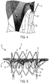
FIG. 4 is an enlarged view of the clamp shown inFIG. 3A ; -
FIG. 5 is a side elevational view showing hooks disposed around the prosthetic heart valve stent ofFIG. 3A ; -
FIG. 6 is a side elevational view of a prosthetic heart valve stent having pivot arms coupled to a frame formed of compliant wires according to a variant of the present disclosure; and -
FIG. 7 is a highly schematic view showing the prosthetic heart valve ofFIG. 3A implanted within the native mitral valve annulus of a patient. - Blood flows through the mitral valve from the left atrium to the left ventricle. As used herein in connection with a prosthetic heart valve, the term "inflow end" refers to the end of the heart valve through which blood enters when the valve is functioning as intended, and the term "outflow end" refers to the end of the heart valve through which blood exits when the valve is functioning as intended. Also as used herein, the terms "substantially," "generally," and "about" are intended to mean that slight deviations from absolute are included within the scope of the term so modified.
-
FIG. 1 is a schematic cutaway representation of a human heart H. The human heart includes two atria and two ventricles: right atrium RA and left atrium LA, and right ventricle RV and left ventricle LV. Heart H further includes aorta A and aortic arch AA. Disposed between the left atrium and the left ventricle is mitral valve MV. The mitral valve, also known as the bicuspid valve or left atrioventricular valve, is a dual-flap that opens as a result of increased pressure in left atrium LA as it fills with blood. As atrial pressure increases above that in left ventricle LV, mitral valve MV opens and blood flows into the left ventricle. Blood flows through heart H in the direction shown by arrows "B". - A dashed arrow, labeled "TA", indicates a transapical approach of implanting a prosthetic heart valve, in this case to replace the mitral valve. In the transapical approach, a small incision is made between the ribs of the patient and into the apex of left ventricle LV to deliver the prosthetic heart valve to the target site. A second dashed arrow, labeled "TS", indicates a transseptal approach of implanting a prosthetic heart valve in which the valve is passed through the septum between right atrium RA and left atrium LA. Other approaches for implanting a prosthetic heart valve are also possible and may be used to implant the collapsible prosthetic heart valve described in the present disclosure.
-
FIG. 2 is a more detailed schematic representation of native mitral valve MV and its associated structures. As previously noted, mitral valve MV includes two flaps or leaflets, posterior leaflet PL and anterior leaflet AL, disposed between left atrium LA and left ventricle LV. Cord-like tendons, known as chordae-tendineae CT, connect the two leaflets to the medial and lateral papillary muscles P. During atrial systole, blood flows from higher pressure in left atrium LA to lower pressure in left ventricle LV. When left ventricle LV contracts during ventricular systole, the increased blood pressure in the chamber pushes the posterior and anterior leaflets to close, preventing the backflow of blood into left atrium LA. Since the blood pressure in left atrium LA is much lower than that in left ventricle LV, the leaflets attempt to evert to low pressure regions. Chordae tendineae CT prevent the eversion by becoming tense, thus pulling on the leaflets and holding them in the closed position. -
Prosthetic heart valve 10, as shown inFIGS. 3A and 3B , is a collapsible and expandable prosthetic heart valve designed to replace the function of the native mitral valve MV (shown inFIGS. 1-2 ) of a patient. For balloon-expandable variants,prosthetic heart valve 10 may be expandable, but not collapsible, or not readily collapsible. When used to replace native mitral valve MV,prosthetic valve 10 may have a low profile so as not to interfere with the heart's electrical conduction system pathways or the atrial function. -
Prosthetic heart valve 10 includes astent 12, which may be formed from biocompatible materials that are capable of self-expansion, for example, shape-memory alloys such as nitinol. Alternatively,stent 12 may be balloon expandable or expandable by another force exerted radially outward on the stent. When expanded,stent 12 may exert a radial force in the direction of arrows R to assist in stabilizingprosthetic heart valve 10 within the native mitral valve annulus. -
Stent 12 extends along a longitudinal axis between aninflow end 14 and anoutflow end 16, and may be substantially cylindrical in shape.Stent 12 may include a plurality ofstruts 18 that formcells 20 connected to one another in one or more annular rows circumferentially extending about the stent. In one example,stent 12 is formed by laser cutting a predetermined pattern into a metallic tube.Cells 20 may be substantially the same size around the perimeter ofstent 12 and along the length of the stent. Alternatively,cells 20 nearinflow end 14 may be larger than the cells nearoutflow end 16. Whenstent 12 is expanded, struts 18 forming acell 20 in the annular row of cells adjacent theoutflow end 16 of the stent may bend about the midsection of the cell (e.g., in a direction orthogonal to the longitudinal axis), as shown inFIG. 3A , such that the lower apex of the cell extends radially outward relative to the midsection of the cell, and the upper apex of the cell extends radially outward relative to the midsection of the cell. - A plurality of commissure attachment features 22 may be provided on
stent 12 for attaching the commissure between two adjacent leaflets to the stent. As shown inFIG. 3A , commissure attachment features 22 may lie at the intersection of twostruts 18 that form onecell 20 at theoutflow end 16 ofstent 12. Commissure attachment features 22 may include one or more eyelets that facilitate the suturing of the leaflet commissure tostent 12. - One or
more retaining elements 24 may be provided at theoutflow end 16 of thestent 12. As shown inFIG. 3A , retainingelements 24 may extend from commissure attachment features 22. Retainingelements 24 are sized to cooperate with a corresponding retaining structure on a delivery device (not shown) for deliveringprosthetic heart valve 10 into the patient. This cooperation minimizes the axial movement ofprosthetic heart valve 10 relative to the delivery device during unsheathing or resheathing procedures, and minimizes rotation of the prosthetic heart valve relative to the delivery device as the delivery device is advanced to the target location and during deployment. - With additional reference to
FIG. 3B ,prosthetic heart valve 10 also includes avalve assembly 26, which may be secured tostent 12 by suturing the valve assembly to struts 18 and/or to commissure attachment features 22. In order to more clearly illustratestent 12 and the additional features described below,valve assembly 26 is not illustrated inFIG. 3A . It will be understood, however, that assembledprosthetic heart valve 10 includes the valve assembly described below and schematically illustrated inFIG. 3B . -
Valve assembly 26 includes acuff 28 and a plurality ofleaflets 30 that open and close collectively to function as a one-way valve. Bothcuff 28 andleaflets 30 may be wholly or partly formed of any suitable biological material, such as bovine or porcine pericardium, or biocompatible polymer, such as polytetrafluorethylene (PTFE), urethanes and the like.Prosthetic heart valve 10 may also include a sealing skirt (not shown) disposed about an abluminal surface ofstent 12. Whenprosthetic heart valve 10 is implanted within the native mitral valve annulus of a patient, the sealing skirt may seal any gaps between the prosthetic heart valve and the native mitral valve annulus to help prevent the backflow of blood into left atrium LA. The sealing skirt may also be formed of any suitable biological material, such as bovine or porcine pericardium, or biocompatible polymer, such as PTFE, urethanes or similar materials. -
Prosthetic heart valve 10 may also include one ormore engagement arms 42 circumferentially mounted aroundstent 12 to engage tissue and stabilize the prosthetic heart valve within the native mitral valve annulus.Engagement arms 42 may be pivotally mounted tostent 12 so as to be transitionable from a collapsed condition in which the engagement arms lie against or within thecells 20 of the collapsed stent during delivery ofprosthetic heart valve 10 into the patient, to an expanded condition in which the engagement arms extend radially outward from the stent after the prosthetic heart valve has been deployed from the delivery device. As illustrated inFIG. 3A , eachengagement arm 42 may include two arm segments that are attached at ends 44 to twostruts 18 forming asingle cell 20, with a loopedportion 46 connecting the other ends of the arm segments together. Thus, whenengagement arms 42 are in the collapsed condition, each engagement arm is completely disposed within a predetermined one of thecells 20 ofstent 12 and lies flush with the stent.Engagement arms 42 may be arranged in any ofcells 20, for example, within every other cell within the annular row adjacent to theoutflow end 16 ofstent 12, as shown inFIG. 3A . -
Prosthetic heart valve 10 may be used to repair a malfunctioning native heart valve, such as a native mitral valve, or an implanted and malfunctioning prosthetic heart valve. When implanted within the native mitral valve annulus,prosthetic heart valve 10 is designed to replace the function of the native mitral valve. The prosthetic heart valve may be delivered to a desired site (e.g., near the native mitral valve annulus) using any suitable delivery device (not shown) such as a catheter, a trocar, a laparoscopic instrument, or the like. During delivery,prosthetic heart valve 10 may be disposed inside the delivery device in the collapsed configuration. The delivery device may be introduced into the patient using a transapical, transseptal or other percutaneous approach and delivered toward the native mitral valve. - Once the delivery device has reached the target site, a physician may unsheathe
prosthetic heart valve 10 to allow the prosthetic heart valve to expand from the collapsed condition to the expanded condition and engage tissue, thereby anchoring the prosthetic heart valve within the native mitral valve annulus. Whenprosthetic heart valve 10 is deployed,stent 12 will be outwardly expanded until it contacts the native valve annulus, such as the mitral valve annulus.Cells 20 in the annular row of cells adjacent theoutflow end 16 ofstent 12 may bend about their midsection such that, when properly positioned, the upper apex of each cell extends outwardly against a portion of the annulus proximate the atrium, and the lower apex of each cells extends outwardly and against a portion of the annulus proximate the ventricle. Further, each ofengagement arms 42 may expand asstent 12 expands. More particularly,engagement arms 42 may transition from the collapsed condition in which they lie against or withincells 20 ofstent 12 to the expanded condition in which each one of the engagement arms pivots outwardly from the stent to capture the posterior leaflet PL and the anterior leaflet AL and provide further anchoring support. Collectively, all of these features are intended to anchorprosthetic heart valve 10 within the mitral valve annulus. - Additional features to more securely anchor and stabilize
prosthetic heart valve 10 within the mitral valve annulus are desirable. In one embodiment,prosthetic heart valve 10 also includes a collapsible and anexpandable frame 32 defining a lumen for receivingstent 12 andvalve assembly 26.Frame 32 may include a plurality of wires or braided strands 33 (collectively hereinafter "wires") formed from compliant biocompatible materials that are capable of self-expansion, for example, shape-memory alloys such as nitinol. Alternatively,frame 32 may be formed from a balloon expandable or other mechanically expandable and compliant material.Clamps 34 couple afirst end 36 offrame 32 tostent 12. As shown inFIG. 3A , clamps 34 may be attached at one end to struts 18 and may lie between twoadjacent cells 20 positioned in the same annular row adjacent to theoutflow end 16 ofstent 12. A plurality ofwires 33 may be grouped together and secured within the other end ofclamps 34, thus forming scallops adjacent thefirst end 36 offrame 32. The scalloped portion preventsframe 32 from interfering with blood flow through theoutflow end 16 ofstent 12 to the left ventricular outflow tract of the heart. -
Frame 32 may flare outwardly relative to the longitudinal axis ofstent 12 from thefirst end 36 of the frame to aradially extending flange 40 at asecond end 38 of the frame. Thesecond end 38 offrame 32 may be disposed about a midsection ofstent 12.Flange 40 is designed to at least partially project into the left atrium of the heart and to anchorstent 12 against the atrium-facing surface of the native mitral valve annulus of the patient. As shown inFIG. 3A , theflange 40 offrame 32 may have a transverse cross-section that is greater than the transverse cross-section of the body of the frame. Referring toFIG. 3B , theflange 40 offrame 32 may have an elliptical or other non-circular transverse cross-section. - When expanded,
frame 32 extends radially outward at an angle fromstent 12. In one embodiment, the angle formed betweenframe 32 andstent 12 is between approximately 45 degrees and approximately 75 degrees, and may be about 60 degrees. Thewires 33 offrame 32 are preferably designed to exhibit a higher compliance thanstent 12. In this manner,frame 32 may expand to a greater diameter thanstent 12 to assist in anchoringprosthetic heart valve 10 within the native heart valve annulus, without damaging the heart tissue that is contacted by the frame. - During deployment of
prosthetic heart valve 10,frame 32 may self-expand simultaneously with the expansion ofstent 12 and project radially outward from an abluminal surface of the stent to engage with the native annulus of mitral valve MV. As shown inFIG. 7 , thecompliant wires 33 offrame 32 may compress in a radially inward direction in a region, identified by the arrow labeled 64, at which the frame engages the native valve annulus.Engagement region 64 is preferably a location spaced from thefirst end 36 offrame 32 and thesecond end 38 of the frame, and may be approximately at the midsection of the frame. In this manner, the highlycompliant wires 33 located betweenengagement region 64 and thefirst end 36 offrame 32 will form asub-annulus bulge 66 at a location inferior to the native mitral annulus and within the left ventricle. The combination ofsub-annulus bulge 66 and the enlargedsecond end 38 offrame 32 sandwiches the native mitral valve annulus and anchorsprosthetic valve 10 within the valve annulus. Due to the highlycompliant wires 33,frame 32 does not exhibit a radial force against the native heart tissue that is large enough to damage the tissue. - The
wires 33 of expandedframe 32 may also fill voids between the sealing skirt of the prosthetic heart valve and the native mitral valve annulus, particularly at thesub-annulus bulge 66, when the prosthetic heart valve has been implanted in the native mitral valve annulus. As a result, thewires 33 offrame 32 may fill irregularities in the native mitral valve annulus and prevent paravalvular leakage betweenprosthetic heart valve 10 and the native mitral valve annulus. - In another embodiment,
prosthetic heart valve 10 may include one or more prongs orcleats 54 having a sharpened tip that penetrates tissue at or near the native valve annulus when the prosthetic heart valve is expanded. In one embodiment, prongs 54 may be provided on one or more ofclamps 34, as shown inFIG. 4 . In other embodiments, prongs 54 may be provided onstent 12,frame 32 and/orengagement arms 42. - Referring to
FIG. 5 , in another embodiment,prosthetic heart valve 10 may include a plurality of collapsible andexpandable hooks 58 mounted about the circumference ofstent 12. Eachhook 58 may include an attached end 60 that lies at the intersection of twostruts 18 that form onecell 20 at theinflow end 14 ofstent 12. Eachhook 58 may then extend in the longitudinal direction ofstent 12 through the scalloped portion offrame 32, terminating at an outwardlycurved end 62 at about the midsection ofstent 12. In this manner, the curved ends 62 ofhooks 58 are positioned to wrap around and capture posterior leaflet PL and anterior leaflet AL whenprosthetic heart valve 10 is anchored within the native annulus of mitral valve MV (FIG. 2 ). As shown inFIG. 5 ,engagement arms 42 may be attached only tocells 20 that do not include hooks 58. For example,engagement arms 42 may be attached to cells aligned in the longitudinal direction ofstent 12 with commissure attachment features 22, while the other cells disposed between adjacent commissure attachment features in the circumferential direction of the stent may include hooks 58. Nevertheless, alternative arrangements are possible. - When
prosthetic heart valve 10 is expanded within the native heart valve, such as the native mitral valve MV, hooks 58 may also expand and wrap around and capture posterior leaflet PL and anterior leaflet AL to further anchor the prosthetic heart in place within the native mitral valve annulus. - In yet another embodiment, the surface of any of the tissue engaging features of
prosthetic heart valve 10, such asstent 12,frame 32,engagement arms 42, clamps 34 and/or hooks 58, may be modified to includefriction inducing elements 56 that increase the frictional forces between the surface of the feature and the heart tissue of the patient when the prosthetic heart valve is implanted within the native heart valve annulus. Thefriction inducing elements 56 may be any micro or macro surface modifications such as cleats, protrusions, ridges and the like. Because the friction-inducingelements 56 are shown inFIG. 4 on a micro scale, the friction-inducing elements are illustrated as stippling. Thus, whenprosthetic heart valve 10 is implanted within a native valve annulus, the prosthetic heart valve is less likely to move within or migrate from the native valve annulus due to the increased friction between the modified surface regions and the native heart valve tissue. -
FIG. 6 illustrates a variant prosthetic heart valve 10' that may include any one or more of the features ofprosthetic heart valve 10, except as described below. Eachclamp 34 of prosthetic heart valve 10' is coupled tostent 12 by asecondary strut 48 extending generally in the longitudinal direction of the stent from afirst end 50 at theoutflow end 16 of the stent to asecond end 52 closer to theinflow end 14 of the stent. Thefirst end 50 of eachsecondary strut 48 may be attached to the intersection of twostruts 18 forming the lower apex of acell 20 in the annular row of cells adjacent theoutflow end 16 of the stent.Clamps 34 may be attached to the second ends 52 ofsecondary struts 48 such that the clamps are disposed adjacent the upper apex of thesame cell 20 to which thefirst end 50 of the secondary strut is attached.Clamps 34 are thus positioned relatively closer to theinflow end 14 ofstent 12 than in the embodiment illustrated inFIG. 3A . As a result of the higher positions ofclamps 34,frame 32 is positioned relatively closer to, or at, theinflow end 14 ofstent 12, relative to the frame ofprosthetic heart valve 10 shown inFIG. 3A . Thesecond end 52 of eachsecondary strut 48 and, in turn, eachclamp 34 is positioned radially outward fromstent 12 and is not attached to the stent. - Variant prosthetic heart valve 10' may also include one or
more pivot arms 61 circumferentially mounted aroundstent 12 to assist in expandingframe 32 and stabilizing the prosthetic heart valve within the native mitral valve annulus. Pivotarms 61 may be pivotally mounted tostent 12 so as to be transitionable from a collapsed condition in which the pivot arms lie against or within thecells 20 of the collapsed stent during delivery ofprosthetic heart valve 10 into the patient, to an expanded condition in which the pivot arms extend radially outward from the stent after the prosthetic heart valve has been deployed from the delivery device. As illustrated inFIG. 6 , eachpivot arm 61 may include two segments that are attached to twostruts 18 forming asingle cell 20, and a looped portion connecting the two segments together. Thus, when pivotarms 61 are in the collapsed condition, each pivot arm is completely disposed within a predetermined one of thecells 20 ofstent 12, or lies substantially flush against the stent. Pivotarms 61 are disposed betweensecondary struts 48 andstent 12 in the radial direction of the stent. The pivot arms are strong enough to pushsecondary struts 48 and/or clamps 34 radially outward when the pivot arms expand and contact the secondary struts and/or clamps to assist in expanding the frame during deployment of prosthetic heart valve 10'. Furthermore, pivotarms 61 may continue to apply a radial outward force onsecondary struts 48 and/or clamps 34 after prosthetic valve 10' has been expanded such thatframe 32 is secured against the native mitral valve annulus after the prosthetic heart valve has been implanted within the native valve annulus. - Any of the above described stabilization features, including
expandable frame 32,engagement arms 42, prongs 54,friction inducing elements 56, hooks 58, or pivotarms 61 may be individually incorporated into a prosthetic heart valve or may be incorporated into a prosthetic heart valve in combination with any one or more of the other stabilization features described herein. - After
prosthetic heart valve 10, 10' has been properly positioned and anchored within the native mitral valve annulus of a patient, the prosthetic heart valve may work as a one-way valve to restore proper function of the heart valve by allowing blood to flow in one direction (e.g., from the left atrium to the left ventricle) while preventing blood from flowing in the opposite direction. - To summarize the foregoing, a prosthetic heart valve includes an expandable stent extending along a longitudinal axis between an inflow end and an outflow end; a valve assembly disposed within the stent; and a collapsible and expandable frame formed of compliant wires, the frame having a body including a first end coupled to the stent, a second end, and a lumen extending therethrough for receiving the stent, whereby when the frame is expanded in the native valve annulus, the compliant wires form an indented region in the frame between the first and second ends of the body and a sub-annulus portion of the frame forms a bulge; and/or
when the frame is expanded, the body of the frame may extend away from the longitudinal axis; and/or
the body of the frame may form an angle with the stent of between approximately 45 degrees and approximately 75 degrees; and/or
the body of the frame may form an angle with the stent of approximately 60 degrees; and/or
the frame may include a flange at the second end of the body, and the flange may have a transverse cross-section greater than a transverse cross-section of the body; and/or
the stent may include a pivot arm pivotable between a collapsed condition in which the pivot arm lies flush with the stent when the stent is in an expanded condition and an expanded condition in which the pivot arm extends radially away from the stent when the stent is in the expanded condition; and/or
the stent may include a plurality of the pivot arms circumferentially disposed about the stent; and/or
the frame may be coupled to the plurality of pivot arms; and/or
the prosthetic heart valve may further include a plurality of clamps coupling the frame to the stent; and/or
at least one of the plurality of clamps may include a prong to anchor into tissue; and/or
a surface of at least one of the plurality of clamps may include a plurality of friction-inducing elements; and/or
the prosthetic heart valve may further include a plurality of expandable hooks disposed circumferentially about the stent for capturing native leaflets; and/or
the frame may include a scalloped portion facing toward the outflow end of the stent. - In another embodiment, a prosthetic heart valve includes an expandable stent including a plurality of struts forming cells; a pivot arm attached to the stent, the pivot arm being pivotable between a collapsed condition in which the pivot arm lies substantially flush with the stent when the stent is in an expanded condition and an expanded condition in which the pivot arm extends radially away from stent when the stent is in the expanded condition; a valve assembly disposed within the stent; and a collapsible and expandable frame formed of wires, the frame having a body forming a lumen extending therethrough for receiving the stent and the valve assembly, the body being coupled to the stent such that pivoting the pivot arm from the collapsed condition to the expanded condition causes the pivot arm to aid in expanding the frame; and/or
- the prosthetic heart valve may further include a secondary strut connected to a predetermined one of the cells and an attachment member coupling the frame to the secondary strut, wherein when the pivot arm is in the expanded condition, the pivot arm exerts an outward radial force on at least one of the secondary strut or the attachment member; and/or
the pivot arm may be disposed at least partially within the predetermined one of the cells; and/or
the secondary strut may extend along a midline of the predetermined one of the cells in a direction substantially parallel to a longitudinal axis of the stent. - Yet another embodiment provides a method of deploying a prosthetic heart valve at a target site, the prosthetic heart valve including an expandable stent having an inflow end and an outflow end, a valve assembly disposed within the stent, and a collapsible and expandable frame coupled to and surrounding the stent. The method includes delivering the prosthetic heart valve within a delivery device in a collapsed condition to a target site adjacent a native valve annulus; expanding the prosthetic heart valve at the target site, whereupon the stent expands and the frame expands into engagement with the native valve annulus; and pressing the frame against the native valve annulus so that an indented region is formed in the frame adjacent the native valve annulus and a portion of the frame below the native valve annulus expands radially outward relative to the indented region; and/or
the expanding step may include expanding a pivot arm attached to the stent from a collapsed condition to an expanded condition, whereupon the pivot arm contacts an attachment member coupling the frame to the stent; and/or
the native valve annulus may be the mitral valve annulus of a patient. - Although the invention herein has been described with reference to particular embodiments, it is to be understood that these embodiments are merely illustrative of the principles and applications of the present invention. It is therefore to be understood that numerous modifications may be made to the illustrative embodiments and that other arrangements may be devised without departing from the spirit and scope of the present disclosure as defined by the appended claims.
Claims (15)
- A prosthetic heart valve, comprising:an expandable stent extending along a longitudinal axis between an inflow end and an outflow end;a valve assembly disposed within the stent; anda collapsible and an expandable frame formed of compliant wires, the frame having a body including a first end coupled to the stent, a second end, and a lumen extending therethrough for receiving the stent, whereby when the frame is expanded in the native valve annulus, the compliant wires form an indented region in the frame between the first and second ends of the body and a sub-annulus portion of the frame forms a bulge.
- The prosthetic heart valve of claim 1, wherein when the frame is expanded, the body of the frame extends away from the longitudinal axis.
- The prosthetic heart valve of claim 2, wherein the body of the frame forms an angle with the stent of between approximately 45 degrees and approximately 75 degrees.
- The prosthetic heart valve of claim 1, wherein the frame includes a flange at the second end of the body, the flange having a transverse cross-section greater than a transverse cross-section of the body.
- The prosthetic heart valve of claim 1, wherein the stent includes a pivot arm pivotable between a collapsed condition in which the pivot arm lies flush with the stent when the stent is in a collapsed expanded condition and an expanded condition in which the pivot arm extends radially away from the stent when the stent is in the expanded condition.
- The prosthetic heart valve of claim 5, wherein the stent includes a plurality of the pivot arms circumferentially disposed about the stent.
- The prosthetic heart valve of claim 6, wherein the frame is coupled to the plurality of pivot arms.
- The prosthetic heart valve of claim 1, further comprising a plurality of clamps coupling the frame to the stent.
- The prosthetic heart valve of claim 8, wherein at least one of the plurality of clamps includes a prong to anchor into tissue.
- The prosthetic heart valve of claim 8, wherein a surface of at least one of the plurality of clamps includes a plurality of friction-inducing elements.
- The prosthetic heart valve of claim 1, further comprising a plurality of expandable hooks disposed circumferentially about the stent for capturing native leaflets.
- The prosthetic heart valve of claim 1, wherein the frame includes a scalloped portion facing toward the outflow end of the stent.
- A prosthetic heart valve, comprising:an expandable stent including a plurality of struts forming cells;a pivot arm attached to the stent, the pivot arm being pivotable between a collapsed condition in which the pivot arm lies substantially flush with the stent when the stent is in a collapsed condition an expanded condition in which the pivot arm extends radially away from stent when the stent is in an expanded condition;a valve assembly disposed within the stent; anda collapsible and an expandable frame formed of wires, the frame having a body forming a lumen extending therethrough for receiving the stent and the valve assembly, the body being coupled to the stent such that pivoting the pivot arm from the collapsed condition to the expanded condition causes the pivot arm to aid in expanding the frame.
- The prosthetic heart valve of claim 13, further comprising a secondary strut connected to a predetermined one of the cells and an attachment member coupling the frame to the secondary strut, wherein when the pivot arm is in the expanded condition, the pivot arm exerts an outward radial force on at least one of the secondary strut or the attachment member.
- The prosthetic heart valve of claim 14, wherein the pivot arm is disposed at least partially within the predetermined one of the cells.
Applications Claiming Priority (1)
| Application Number | Priority Date | Filing Date | Title |
|---|---|---|---|
| US202063022647P | 2020-05-11 | 2020-05-11 |
Publications (2)
| Publication Number | Publication Date |
|---|---|
| EP3909548A1 true EP3909548A1 (en) | 2021-11-17 |
| EP3909548B1 EP3909548B1 (en) | 2023-11-15 |
Family
ID=75904829
Family Applications (1)
| Application Number | Title | Priority Date | Filing Date |
|---|---|---|---|
| EP21173299.5A Active EP3909548B1 (en) | 2020-05-11 | 2021-05-11 | Transcatheter mitral valve fixation concepts |
Country Status (2)
| Country | Link |
|---|---|
| US (1) | US12427018B2 (en) |
| EP (1) | EP3909548B1 (en) |
Families Citing this family (13)
| Publication number | Priority date | Publication date | Assignee | Title |
|---|---|---|---|---|
| US20090276040A1 (en) * | 2008-05-01 | 2009-11-05 | Edwards Lifesciences Corporation | Device and method for replacing mitral valve |
| US9949825B2 (en) | 2014-02-18 | 2018-04-24 | St. Jude Medical, Cardiology Division, Inc. | Bowed runners and corresponding valve assemblies for paravalvular leak protection |
| WO2019224577A1 (en) | 2018-05-23 | 2019-11-28 | Sorin Group Italia S.R.L. | A cardiac valve prosthesis |
| IL319705B2 (en) | 2020-02-06 | 2026-03-01 | Laplace Interventional Inc | Transcatheter heart valve prosthesis assembled inside heart chambers or blood vessels |
| US11197755B1 (en) | 2020-10-28 | 2021-12-14 | Occam Labs LLC | Systems, devices and methods for folded unibody heart valve stents |
| US11246726B1 (en) | 2021-02-10 | 2022-02-15 | Occam Labs LLC | Systems, devices and methods for delivery systems |
| CN115813607B (en) * | 2021-11-15 | 2026-01-23 | 南京圣德医疗科技有限公司 | Self-expanding biological valve |
| US11510777B1 (en) | 2022-02-10 | 2022-11-29 | Laplace Interventional Inc. | Prosthetic heart valves |
| JP7856845B2 (en) * | 2022-07-12 | 2026-05-11 | 上海以心医療器械有限公司 | Heart valve stents and artificial heart valves |
| US11712336B1 (en) | 2022-07-20 | 2023-08-01 | Laplace Interventional Inc. | Prosthetic heart valves |
| WO2024192413A2 (en) | 2023-03-15 | 2024-09-19 | Capstan Medical Inc. | Hooked spool delivery systems |
| CN119950119A (en) * | 2023-12-29 | 2025-05-09 | 元心科技(深圳)有限公司 | Implantable device and method of manufacturing the same |
| US12440336B1 (en) | 2025-02-11 | 2025-10-14 | Laplace Interventional Inc. | Prosthetic heart valves |
Citations (2)
| Publication number | Priority date | Publication date | Assignee | Title |
|---|---|---|---|---|
| US20170049564A1 (en) * | 2013-03-11 | 2017-02-23 | St. Jude Medical, Cardiology Division, Inc. | Transcatheter valve replacement |
| US20200113683A1 (en) * | 2018-10-15 | 2020-04-16 | St. Jude Medical, Cardiology Division, Inc. | Braid Connections For Prosthetic Heart Valves |
Family Cites Families (179)
| Publication number | Priority date | Publication date | Assignee | Title |
|---|---|---|---|---|
| US3657744A (en) | 1970-05-08 | 1972-04-25 | Univ Minnesota | Method for fixing prosthetic implants in a living body |
| US4491986A (en) | 1976-05-12 | 1985-01-08 | Shlomo Gabbay | Heart valve |
| US4275469A (en) | 1979-12-13 | 1981-06-30 | Shelhigh Inc. | Prosthetic heart valve |
| US4759758A (en) | 1984-12-07 | 1988-07-26 | Shlomo Gabbay | Prosthetic heart valve |
| DE3640745A1 (en) | 1985-11-30 | 1987-06-04 | Ernst Peter Prof Dr M Strecker | Catheter for producing or extending connections to or between body cavities |
| US4878906A (en) | 1986-03-25 | 1989-11-07 | Servetus Partnership | Endoprosthesis for repairing a damaged vessel |
| US4994077A (en) | 1989-04-21 | 1991-02-19 | Dobben Richard L | Artificial heart valve for implantation in a blood vessel |
| US5411552A (en) | 1990-05-18 | 1995-05-02 | Andersen; Henning R. | Valve prothesis for implantation in the body and a catheter for implanting such valve prothesis |
| DK124690D0 (en) | 1990-05-18 | 1990-05-18 | Henning Rud Andersen | FAT PROTECTION FOR IMPLEMENTATION IN THE BODY FOR REPLACEMENT OF NATURAL FLEET AND CATS FOR USE IN IMPLEMENTING A SUCH FAT PROTECTION |
| US5843167A (en) | 1993-04-22 | 1998-12-01 | C. R. Bard, Inc. | Method and apparatus for recapture of hooked endoprosthesis |
| US5480423A (en) | 1993-05-20 | 1996-01-02 | Boston Scientific Corporation | Prosthesis delivery |
| US5713950A (en) | 1993-11-01 | 1998-02-03 | Cox; James L. | Method of replacing heart valves using flexible tubes |
| EP0657147B1 (en) | 1993-11-04 | 1999-08-04 | C.R. Bard, Inc. | Non-migrating vascular prosthesis |
| US5415664A (en) | 1994-03-30 | 1995-05-16 | Corvita Corporation | Method and apparatus for introducing a stent or a stent-graft |
| GB9522332D0 (en) | 1995-11-01 | 1996-01-03 | Biocompatibles Ltd | Braided stent |
| DE69526857T2 (en) | 1995-11-27 | 2003-01-02 | Schneider (Europe) Gmbh, Buelach | Stent for use in one pass |
| US7238197B2 (en) | 2000-05-30 | 2007-07-03 | Devax, Inc. | Endoprosthesis deployment system for treating vascular bifurcations |
| US5855601A (en) | 1996-06-21 | 1999-01-05 | The Trustees Of Columbia University In The City Of New York | Artificial heart valve and method and device for implanting the same |
| EP0850607A1 (en) | 1996-12-31 | 1998-07-01 | Cordis Corporation | Valve prosthesis for implantation in body channels |
| US6488702B1 (en) | 1997-01-24 | 2002-12-03 | Jomed Gmbh | Bistable spring construction for a stent and other medical apparatus |
| US5961549A (en) | 1997-04-03 | 1999-10-05 | Baxter International Inc. | Multi-leaflet bioprosthetic heart valve |
| US5954766A (en) | 1997-09-16 | 1999-09-21 | Zadno-Azizi; Gholam-Reza | Body fluid flow control device |
| US5938697A (en) | 1998-03-04 | 1999-08-17 | Scimed Life Systems, Inc. | Stent having variable properties |
| US5935163A (en) | 1998-03-31 | 1999-08-10 | Shelhigh, Inc. | Natural tissue heart valve prosthesis |
| US7452371B2 (en) | 1999-06-02 | 2008-11-18 | Cook Incorporated | Implantable vascular device |
| US6254564B1 (en) | 1998-09-10 | 2001-07-03 | Percardia, Inc. | Left ventricular conduit with blood vessel graft |
| US6113612A (en) * | 1998-11-06 | 2000-09-05 | St. Jude Medical Cardiovascular Group, Inc. | Medical anastomosis apparatus |
| US6214036B1 (en) | 1998-11-09 | 2001-04-10 | Cordis Corporation | Stent which is easily recaptured and repositioned within the body |
| DE19857887B4 (en) | 1998-12-15 | 2005-05-04 | Fraunhofer-Gesellschaft zur Förderung der angewandten Forschung e.V. | Anchoring support for a heart valve prosthesis |
| US6558414B2 (en) | 1999-02-02 | 2003-05-06 | Impra, Inc. | Partial encapsulation of stents using strips and bands |
| US6090140A (en) | 1999-02-17 | 2000-07-18 | Shelhigh, Inc. | Extra-anatomic heart valve apparatus |
| WO2000053104A1 (en) * | 1999-03-09 | 2000-09-14 | St. Jude Medical Cardiovascular Group, Inc. | Medical grafting methods and apparatus |
| US6264691B1 (en) | 1999-04-23 | 2001-07-24 | Shlomo Gabbay | Apparatus and method for supporting a heart valve |
| HK1050470A1 (en) | 1999-09-10 | 2003-06-27 | E. Thorpe Patricia | Endovascular treatment for chronic venous insufficiency |
| US20020123790A1 (en) * | 1999-09-28 | 2002-09-05 | White Geoffrey Hamilton | Enhanced engagement member for anchoring prosthetic devices in body lumen |
| US6440164B1 (en) | 1999-10-21 | 2002-08-27 | Scimed Life Systems, Inc. | Implantable prosthetic valve |
| US8016877B2 (en) | 1999-11-17 | 2011-09-13 | Medtronic Corevalve Llc | Prosthetic valve for transluminal delivery |
| US7018406B2 (en) | 1999-11-17 | 2006-03-28 | Corevalve Sa | Prosthetic valve for transluminal delivery |
| FR2815844B1 (en) | 2000-10-31 | 2003-01-17 | Jacques Seguin | TUBULAR SUPPORT FOR THE PERCUTANEOUS POSITIONING OF A REPLACEMENT HEART VALVE |
| US8579966B2 (en) | 1999-11-17 | 2013-11-12 | Medtronic Corevalve Llc | Prosthetic valve for transluminal delivery |
| FR2800984B1 (en) | 1999-11-17 | 2001-12-14 | Jacques Seguin | DEVICE FOR REPLACING A HEART VALVE PERCUTANEOUSLY |
| US20070043435A1 (en) * | 1999-11-17 | 2007-02-22 | Jacques Seguin | Non-cylindrical prosthetic valve system for transluminal delivery |
| US7195641B2 (en) | 1999-11-19 | 2007-03-27 | Advanced Bio Prosthetic Surfaces, Ltd. | Valvular prostheses having metal or pseudometallic construction and methods of manufacture |
| US6458153B1 (en) | 1999-12-31 | 2002-10-01 | Abps Venture One, Ltd. | Endoluminal cardiac and venous valve prostheses and methods of manufacture and delivery thereof |
| CA2398640C (en) | 2000-01-31 | 2011-06-14 | Cook Biotech Incorporated | Stent valves and uses of same |
| KR100786028B1 (en) | 2000-02-03 | 2007-12-17 | 쿡 인코포레이티드 | Implantable Vascular Device |
| US6454799B1 (en) | 2000-04-06 | 2002-09-24 | Edwards Lifesciences Corporation | Minimally-invasive heart valves and methods of use |
| US6517573B1 (en) * | 2000-04-11 | 2003-02-11 | Endovascular Technologies, Inc. | Hook for attaching to a corporeal lumen and method of manufacturing |
| US6610088B1 (en) | 2000-05-03 | 2003-08-26 | Shlomo Gabbay | Biologically covered heart valve prosthesis |
| US6368348B1 (en) | 2000-05-15 | 2002-04-09 | Shlomo Gabbay | Annuloplasty prosthesis for supporting an annulus of a heart valve |
| US6869444B2 (en) | 2000-05-22 | 2005-03-22 | Shlomo Gabbay | Low invasive implantable cardiac prosthesis and method for helping improve operation of a heart valve |
| US6419695B1 (en) | 2000-05-22 | 2002-07-16 | Shlomo Gabbay | Cardiac prosthesis for helping improve operation of a heart valve |
| US6695878B2 (en) * | 2000-06-26 | 2004-02-24 | Rex Medical, L.P. | Vascular device for valve leaflet apposition |
| WO2002022054A1 (en) | 2000-09-12 | 2002-03-21 | Gabbay S | Valvular prosthesis and method of using same |
| US7510572B2 (en) | 2000-09-12 | 2009-03-31 | Shlomo Gabbay | Implantation system for delivery of a heart valve prosthesis |
| US6685625B2 (en) | 2000-09-26 | 2004-02-03 | Shlomo Gabbay | Curved implantable sheath and method of making same |
| US20020036220A1 (en) | 2000-09-26 | 2002-03-28 | Shlomo Gabbay | Curved implantable sheath and method of making same |
| US6783556B1 (en) | 2000-09-26 | 2004-08-31 | Shlomo Gabbay | System and method for making a calotte-shaped implantable sheath |
| US6517576B2 (en) | 2000-12-11 | 2003-02-11 | Shlomo Gabbay | Implantable patch prosthesis having one or more cusps for improved competency |
| ES2253325T3 (en) | 2000-12-15 | 2006-06-01 | ANGIOMED GMBH & CO. MEDIZINTECHNIK KG | ENDOVASCULAR PROTESIS WITH VALVE. |
| US6468660B2 (en) | 2000-12-29 | 2002-10-22 | St. Jude Medical, Inc. | Biocompatible adhesives |
| US6623518B2 (en) | 2001-02-26 | 2003-09-23 | Ev3 Peripheral, Inc. | Implant delivery system with interlock |
| WO2002067782A2 (en) | 2001-02-26 | 2002-09-06 | Ev3 Peripheral, Inc. | Implant delivery system with interlock |
| US7556646B2 (en) | 2001-09-13 | 2009-07-07 | Edwards Lifesciences Corporation | Methods and apparatuses for deploying minimally-invasive heart valves |
| DE10121210B4 (en) | 2001-04-30 | 2005-11-17 | Universitätsklinikum Freiburg | Anchoring element for the intraluminal anchoring of a heart valve replacement and method for its production |
| US7087088B2 (en) * | 2001-05-24 | 2006-08-08 | Torax Medical, Inc. | Methods and apparatus for regulating the flow of matter through body tubing |
| FR2828091B1 (en) | 2001-07-31 | 2003-11-21 | Seguin Jacques | ASSEMBLY ALLOWING THE PLACEMENT OF A PROTHETIC VALVE IN A BODY DUCT |
| US20080021552A1 (en) | 2001-10-09 | 2008-01-24 | Shlomo Gabbay | Apparatus To Facilitate Implantation |
| US6893460B2 (en) | 2001-10-11 | 2005-05-17 | Percutaneous Valve Technologies Inc. | Implantable prosthetic valve |
| DE10221076A1 (en) | 2002-05-11 | 2003-11-27 | Ruesch Willy Gmbh | stent |
| AU2003256499A1 (en) * | 2002-07-11 | 2004-02-02 | Setagon, Inc. | Expandable body having deployable microstructures and related methods |
| US20050096731A1 (en) * | 2002-07-11 | 2005-05-05 | Kareen Looi | Cell seeded expandable body |
| US7137184B2 (en) | 2002-09-20 | 2006-11-21 | Edwards Lifesciences Corporation | Continuous heart valve support frame and method of manufacture |
| US6814746B2 (en) | 2002-11-01 | 2004-11-09 | Ev3 Peripheral, Inc. | Implant delivery system with marker interlock |
| FR2847800B1 (en) | 2002-11-28 | 2005-10-14 | Perouse Laboratoires | INTERCHANGEABLE PROTHETIC VALVE |
| FR2850008A1 (en) | 2003-01-17 | 2004-07-23 | Daniel Roux | Vascular prosthesis has tube and collar for adapting to blood vessel ends of different diameters |
| ATE401843T1 (en) | 2003-03-20 | 2008-08-15 | Aortech Internat Plc | VALVE |
| US7717952B2 (en) | 2003-04-24 | 2010-05-18 | Cook Incorporated | Artificial prostheses with preferred geometries |
| CA2523262C (en) | 2003-04-24 | 2012-01-24 | Cook Incorporated | Artificial valve prosthesis with improved flow dynamics |
| US20040260394A1 (en) * | 2003-06-20 | 2004-12-23 | Medtronic Vascular, Inc. | Cardiac valve annulus compressor system |
| US7201772B2 (en) | 2003-07-08 | 2007-04-10 | Ventor Technologies, Ltd. | Fluid flow prosthetic device |
| US7160322B2 (en) | 2003-08-13 | 2007-01-09 | Shlomo Gabbay | Implantable cardiac prosthesis for mitigating prolapse of a heart valve |
| US20060259137A1 (en) | 2003-10-06 | 2006-11-16 | Jason Artof | Minimally invasive valve replacement system |
| US10219899B2 (en) | 2004-04-23 | 2019-03-05 | Medtronic 3F Therapeutics, Inc. | Cardiac valve replacement systems |
| US8343213B2 (en) | 2003-12-23 | 2013-01-01 | Sadra Medical, Inc. | Leaflet engagement elements and methods for use thereof |
| DE10394350B4 (en) | 2003-12-23 | 2018-05-17 | Cormove | To be implanted in a lumen to be implanted parts set and prosthesis the same |
| US20050137686A1 (en) | 2003-12-23 | 2005-06-23 | Sadra Medical, A Delaware Corporation | Externally expandable heart valve anchor and method |
| US9005273B2 (en) | 2003-12-23 | 2015-04-14 | Sadra Medical, Inc. | Assessing the location and performance of replacement heart valves |
| US8828078B2 (en) | 2003-12-23 | 2014-09-09 | Sadra Medical, Inc. | Methods and apparatus for endovascular heart valve replacement comprising tissue grasping elements |
| US8840663B2 (en) | 2003-12-23 | 2014-09-23 | Sadra Medical, Inc. | Repositionable heart valve method |
| US8182528B2 (en) | 2003-12-23 | 2012-05-22 | Sadra Medical, Inc. | Locking heart valve anchor |
| US7311730B2 (en) | 2004-02-13 | 2007-12-25 | Shlomo Gabbay | Support apparatus and heart valve prosthesis for sutureless implantation |
| US7247167B2 (en) | 2004-02-19 | 2007-07-24 | Shlomo Gabbay | Low profile heart valve prosthesis |
| ITTO20040135A1 (en) | 2004-03-03 | 2004-06-03 | Sorin Biomedica Cardio Spa | CARDIAC VALVE PROSTHESIS |
| EP2308425B2 (en) | 2004-03-11 | 2023-10-18 | Percutaneous Cardiovascular Solutions Pty Limited | Percutaneous Heart Valve Prosthesis |
| US20050256566A1 (en) | 2004-05-03 | 2005-11-17 | Shlomo Gabbay | Apparatus and method for improving ventricular function |
| US7374573B2 (en) | 2004-05-03 | 2008-05-20 | Shlomo Gabbay | System and method for improving ventricular function |
| US20060122692A1 (en) | 2004-05-10 | 2006-06-08 | Ran Gilad | Stent valve and method of using same |
| US20060008497A1 (en) | 2004-07-09 | 2006-01-12 | Shlomo Gabbay | Implantable apparatus having improved biocompatibility and process of making the same |
| FR2874812B1 (en) | 2004-09-07 | 2007-06-15 | Perouse Soc Par Actions Simpli | INTERCHANGEABLE PROTHETIC VALVE |
| CA3050938C (en) | 2004-10-02 | 2021-10-19 | Edwards Lifesciences Cardiaq Llc | Methods and devices for repair or replacement of heart valves or adjacent tissue without the need for full cardiopulmonary support |
| US8562672B2 (en) | 2004-11-19 | 2013-10-22 | Medtronic, Inc. | Apparatus for treatment of cardiac valves and method of its manufacture |
| US7544205B2 (en) | 2004-12-20 | 2009-06-09 | Cook Incorporated | Intraluminal support frame and medical devices including the support frame |
| BRPI0519298A2 (en) | 2005-01-05 | 2009-01-06 | Cleveland Clinic Foundation | Method of preparing a biological tissue fixed |
| DE102005003632A1 (en) | 2005-01-20 | 2006-08-17 | Fraunhofer-Gesellschaft zur Förderung der angewandten Forschung e.V. | Catheter for the transvascular implantation of heart valve prostheses |
| ITTO20050074A1 (en) | 2005-02-10 | 2006-08-11 | Sorin Biomedica Cardio Srl | CARDIAC VALVE PROSTHESIS |
| US7331991B2 (en) | 2005-02-25 | 2008-02-19 | California Institute Of Technology | Implantable small percutaneous valve and methods of delivery |
| SE531468C2 (en) | 2005-04-21 | 2009-04-14 | Edwards Lifesciences Ag | An apparatus for controlling blood flow |
| EP3266414B1 (en) | 2005-05-12 | 2024-07-17 | Covidien LP | Implant delivery system with interlocked rx port orientation |
| US7914569B2 (en) | 2005-05-13 | 2011-03-29 | Medtronics Corevalve Llc | Heart valve prosthesis and methods of manufacture and use |
| WO2006127412A1 (en) | 2005-05-20 | 2006-11-30 | The Cleveland Clinic Foundation | Apparatus and methods for repairing the function of a diseased valve and method for making same |
| WO2007013999A2 (en) | 2005-07-21 | 2007-02-01 | Florida International University | Collapsible heart valve with polymer leaflets |
| US8790396B2 (en) | 2005-07-27 | 2014-07-29 | Medtronic 3F Therapeutics, Inc. | Methods and systems for cardiac valve delivery |
| US20080269879A1 (en) | 2005-07-27 | 2008-10-30 | Rahul Dilip Sathe | Implantable Prosthetic Vascular Valve |
| US8702777B2 (en) | 2005-08-22 | 2014-04-22 | Incept, Llc | Steep-taper flared stents and apparatus and methods for delivering them |
| US20070067029A1 (en) | 2005-09-16 | 2007-03-22 | Shlomo Gabbay | Support apparatus to facilitate implantation of cardiac prosthesis |
| US8092525B2 (en) | 2005-10-26 | 2012-01-10 | Cardiosolutions, Inc. | Heart valve implant |
| US20070118210A1 (en) | 2005-11-18 | 2007-05-24 | Leonard Pinchuk | Trileaflet Heart Valve |
| MX2008008068A (en) | 2005-12-22 | 2008-09-10 | Symetis Sa | Stent-valves for valve replacement and associated methods and systems for surgery. |
| US20070213813A1 (en) | 2005-12-22 | 2007-09-13 | Symetis Sa | Stent-valves for valve replacement and associated methods and systems for surgery |
| US8075615B2 (en) | 2006-03-28 | 2011-12-13 | Medtronic, Inc. | Prosthetic cardiac valve formed from pericardium material and methods of making same |
| US7524331B2 (en) | 2006-04-06 | 2009-04-28 | Medtronic Vascular, Inc. | Catheter delivered valve having a barrier to provide an enhanced seal |
| US20070244545A1 (en) | 2006-04-14 | 2007-10-18 | Medtronic Vascular, Inc. | Prosthetic Conduit With Radiopaque Symmetry Indicators |
| EP3400908B2 (en) | 2006-05-30 | 2026-04-22 | Cook Medical Technologies LLC | Artificial valve prosthesis |
| US8298281B2 (en) * | 2006-07-18 | 2012-10-30 | Cordis Corporation | Twisted anchoring barb for stent of abdominal aortic aneurysm (AAA) device |
| US20080097595A1 (en) | 2006-08-22 | 2008-04-24 | Shlomo Gabbay | Intraventricular cardiac prosthesis |
| US8876895B2 (en) | 2006-09-19 | 2014-11-04 | Medtronic Ventor Technologies Ltd. | Valve fixation member having engagement arms |
| US7534261B2 (en) | 2006-10-02 | 2009-05-19 | Edwards Lifesciences Corporation | Sutureless heart valve attachment |
| US8747459B2 (en) | 2006-12-06 | 2014-06-10 | Medtronic Corevalve Llc | System and method for transapical delivery of an annulus anchored self-expanding valve |
| FR2909857B1 (en) | 2006-12-14 | 2009-03-06 | Perouse Soc Par Actions Simpli | Endovalve. |
| US8236045B2 (en) | 2006-12-22 | 2012-08-07 | Edwards Lifesciences Corporation | Implantable prosthetic valve assembly and method of making the same |
| US20100087907A1 (en) | 2007-02-16 | 2010-04-08 | Emory University | Apparatus And Methods For Treating The Aorta |
| JP5367700B2 (en) | 2007-06-04 | 2013-12-11 | セント ジュード メディカル インコーポレイテッド | Prosthetic heart valve |
| JP2010528760A (en) | 2007-06-08 | 2010-08-26 | セント ジュード メディカル インコーポレイテッド | Device for transcatheter prosthetic heart valve implantation and access closure |
| ES2475144T3 (en) | 2007-06-26 | 2014-07-10 | St. Jude Medical, Inc. | Apparatus for implanting prosthetic heart valves folding / expandable |
| JP5419875B2 (en) | 2007-08-24 | 2014-02-19 | セント ジュード メディカル インコーポレイテッド | Artificial aortic heart valve |
| US8425593B2 (en) | 2007-09-26 | 2013-04-23 | St. Jude Medical, Inc. | Collapsible prosthetic heart valves |
| US8454686B2 (en) | 2007-09-28 | 2013-06-04 | St. Jude Medical, Inc. | Two-stage collapsible/expandable prosthetic heart valves and anchoring systems |
| WO2009045334A1 (en) | 2007-09-28 | 2009-04-09 | St. Jude Medical, Inc. | Collapsible/expandable prosthetic heart valves with native calcified leaflet retention features |
| US20090138079A1 (en) | 2007-10-10 | 2009-05-28 | Vector Technologies Ltd. | Prosthetic heart valve for transfemoral delivery |
| US9848981B2 (en) | 2007-10-12 | 2017-12-26 | Mayo Foundation For Medical Education And Research | Expandable valve prosthesis with sealing mechanism |
| ES2380555T3 (en) | 2007-11-05 | 2012-05-16 | St. Jude Medical, Inc. | Foldable / expandable prosthetic heart valves with non-expandable stent brackets and recovery features |
| US20080114452A1 (en) | 2007-11-14 | 2008-05-15 | Shlomo Gabbay | Prosthesis exhibiting post-implantation size change |
| AU2009205739B2 (en) | 2008-01-16 | 2014-09-25 | St. Jude Medical, Inc. | Delivery and retrieval systems for collapsible/expandable prosthetic heart valves |
| US8163007B2 (en) * | 2008-02-08 | 2012-04-24 | Cook Medical Technologies Llc | Stent designs for use with one or more trigger wires |
| CA2715448C (en) | 2008-02-25 | 2017-06-13 | Medtronic Vascular Inc. | Infundibular reducer devices |
| US8398704B2 (en) * | 2008-02-26 | 2013-03-19 | Jenavalve Technology, Inc. | Stent for the positioning and anchoring of a valvular prosthesis in an implantation site in the heart of a patient |
| US9168130B2 (en) * | 2008-02-26 | 2015-10-27 | Jenavalve Technology Gmbh | Stent for the positioning and anchoring of a valvular prosthesis in an implantation site in the heart of a patient |
| CN102083391B (en) * | 2008-04-23 | 2015-02-18 | 麦德托尼克公司 | Stented heart valve devices |
| ATE554731T1 (en) | 2008-05-16 | 2012-05-15 | Sorin Biomedica Cardio Srl | ATRAAUMATIC PROSTHETIC HEART VALVE PROSTHESIS |
| HUE047762T2 (en) | 2008-06-06 | 2020-05-28 | Edwards Lifesciences Corp | Low profile transcatheter heart valve |
| WO2010008549A1 (en) | 2008-07-15 | 2010-01-21 | St. Jude Medical, Inc. | Axially anchoring collapsible and re-expandable prosthetic heart valves for various disease states |
| EP4215162A1 (en) | 2008-07-15 | 2023-07-26 | St. Jude Medical, LLC | Collapsible and re-expandable prosthetic heart valve cuff designs and complementary technological applications |
| DE202008009610U1 (en) | 2008-07-17 | 2008-12-11 | Nvt Ag | Prosthetic heart valve system |
| US9265607B2 (en) | 2009-02-20 | 2016-02-23 | St. Jude Medical, Inc. | Devices and methods for collapsing prosthetic heart valves |
| US20100217382A1 (en) | 2009-02-25 | 2010-08-26 | Edwards Lifesciences | Mitral valve replacement with atrial anchoring |
| BRPI1008902A2 (en) | 2009-02-27 | 2016-03-15 | St Jude Medical | prosthetic heart valve. |
| AU2010236288A1 (en) | 2009-04-15 | 2011-10-20 | Cardiaq Valve Technologies, Inc. | Vascular implant and delivery system |
| US8845722B2 (en) | 2009-08-03 | 2014-09-30 | Shlomo Gabbay | Heart valve prosthesis and method of implantation thereof |
| AU2010315030B2 (en) | 2009-11-05 | 2016-03-10 | The Trustees Of The University Of Pennsylvania | Valve prosthesis |
| DE102009060228B4 (en) * | 2009-12-23 | 2014-12-04 | Acandis Gmbh & Co. Kg | Medical devices |
| US9072603B2 (en) * | 2010-02-24 | 2015-07-07 | Medtronic Ventor Technologies, Ltd. | Mitral prosthesis and methods for implantation |
| EP2444030A1 (en) * | 2010-08-31 | 2012-04-25 | Biotronik AG | Medical valve implant for implantation in an animal body and/or human body |
| USD652927S1 (en) | 2010-09-20 | 2012-01-24 | St. Jude Medical, Inc. | Surgical stent |
| USD654170S1 (en) | 2010-09-20 | 2012-02-14 | St. Jude Medical, Inc. | Stent connections |
| USD653341S1 (en) | 2010-09-20 | 2012-01-31 | St. Jude Medical, Inc. | Surgical stent |
| USD652926S1 (en) | 2010-09-20 | 2012-01-24 | St. Jude Medical, Inc. | Forked end |
| USD660433S1 (en) | 2010-09-20 | 2012-05-22 | St. Jude Medical, Inc. | Surgical stent assembly |
| USD660967S1 (en) | 2010-09-20 | 2012-05-29 | St. Jude Medical, Inc. | Surgical stent |
| USD654169S1 (en) | 2010-09-20 | 2012-02-14 | St. Jude Medical Inc. | Forked ends |
| USD653343S1 (en) | 2010-09-20 | 2012-01-31 | St. Jude Medical, Inc. | Surgical cuff |
| USD660432S1 (en) | 2010-09-20 | 2012-05-22 | St. Jude Medical, Inc. | Commissure point |
| USD684692S1 (en) | 2010-09-20 | 2013-06-18 | St. Jude Medical, Inc. | Forked ends |
| USD648854S1 (en) | 2010-09-20 | 2011-11-15 | St. Jude Medical, Inc. | Commissure points |
| USD653342S1 (en) | 2010-09-20 | 2012-01-31 | St. Jude Medical, Inc. | Stent connections |
| US9039757B2 (en) * | 2011-10-19 | 2015-05-26 | Twelve, Inc. | Prosthetic heart valve devices, prosthetic mitral valves and associated systems and methods |
| US9962260B2 (en) * | 2015-03-24 | 2018-05-08 | St. Jude Medical, Cardiology Division, Inc. | Prosthetic mitral valve |
| US10321992B2 (en) * | 2016-02-01 | 2019-06-18 | Medtronic, Inc. | Heart valve prostheses having multiple support arms and methods for percutaneous heart valve replacement |
| WO2017196909A1 (en) * | 2016-05-12 | 2017-11-16 | St. Jude Medical, Cardiology Division, Inc. | Mitral heart valve replacement |
-
2021
- 2021-04-05 US US17/222,198 patent/US12427018B2/en active Active
- 2021-05-11 EP EP21173299.5A patent/EP3909548B1/en active Active
Patent Citations (2)
| Publication number | Priority date | Publication date | Assignee | Title |
|---|---|---|---|---|
| US20170049564A1 (en) * | 2013-03-11 | 2017-02-23 | St. Jude Medical, Cardiology Division, Inc. | Transcatheter valve replacement |
| US20200113683A1 (en) * | 2018-10-15 | 2020-04-16 | St. Jude Medical, Cardiology Division, Inc. | Braid Connections For Prosthetic Heart Valves |
Also Published As
| Publication number | Publication date |
|---|---|
| US20210346153A1 (en) | 2021-11-11 |
| US12427018B2 (en) | 2025-09-30 |
| EP3909548B1 (en) | 2023-11-15 |
Similar Documents
| Publication | Publication Date | Title |
|---|---|---|
| US12427018B2 (en) | Transcatheter mitral valve fixation concepts | |
| US11246706B2 (en) | Transcatheter mitral valve stent frames | |
| US12295837B2 (en) | Mitral heart valve replacement | |
| US11311375B2 (en) | Stents with anchoring sections | |
| EP4342425B1 (en) | Prosthetic tricuspid heart valve | |
| US10864076B2 (en) | Transapical mitral valve replacement | |
| US11278396B2 (en) | Transcatheter mitral valve design | |
| CN111465369A (en) | Artificial valve leaflet device | |
| CN110520080A (en) | Prosthetic heart valve device and associated system and method | |
| US11678980B2 (en) | Fully-transseptal apical pad with pulley for tensioning | |
| US20230355381A1 (en) | Detachable Cell Configuration for Valve in Valve | |
| US12144727B2 (en) | Tether attachment for mitral valve | |
| US20230025890A1 (en) | Transcatheter Valve To Treat Small Native Mitral Anatomy | |
| US20210205080A1 (en) | Fully Deployable And Recapturable Prosthetic Heart Valve | |
| US20230372092A1 (en) | Fully-Transseptal Cinching Apical Pad | |
| US20240390135A1 (en) | Single Frame Tethered Transcatheter Heart Valve | |
| WO2025049266A1 (en) | Prosthetic mitral valve for treating patients with small annulus dimensions |
Legal Events
| Date | Code | Title | Description |
|---|---|---|---|
| PUAI | Public reference made under article 153(3) epc to a published international application that has entered the european phase |
Free format text: ORIGINAL CODE: 0009012 |
|
| STAA | Information on the status of an ep patent application or granted ep patent |
Free format text: STATUS: THE APPLICATION HAS BEEN PUBLISHED |
|
| AK | Designated contracting states |
Kind code of ref document: A1 Designated state(s): AL AT BE BG CH CY CZ DE DK EE ES FI FR GB GR HR HU IE IS IT LI LT LU LV MC MK MT NL NO PL PT RO RS SE SI SK SM TR |
|
| B565 | Issuance of search results under rule 164(2) epc |
Effective date: 20210929 |
|
| STAA | Information on the status of an ep patent application or granted ep patent |
Free format text: STATUS: REQUEST FOR EXAMINATION WAS MADE |
|
| 17P | Request for examination filed |
Effective date: 20220517 |
|
| STAA | Information on the status of an ep patent application or granted ep patent |
Free format text: STATUS: EXAMINATION IS IN PROGRESS |
|
| 17Q | First examination report despatched |
Effective date: 20221213 |
|
| GRAP | Despatch of communication of intention to grant a patent |
Free format text: ORIGINAL CODE: EPIDOSNIGR1 |
|
| STAA | Information on the status of an ep patent application or granted ep patent |
Free format text: STATUS: GRANT OF PATENT IS INTENDED |
|
| INTG | Intention to grant announced |
Effective date: 20230623 |
|
| P01 | Opt-out of the competence of the unified patent court (upc) registered |
Effective date: 20230616 |
|
| GRAS | Grant fee paid |
Free format text: ORIGINAL CODE: EPIDOSNIGR3 |
|
| GRAA | (expected) grant |
Free format text: ORIGINAL CODE: 0009210 |
|
| STAA | Information on the status of an ep patent application or granted ep patent |
Free format text: STATUS: THE PATENT HAS BEEN GRANTED |
|
| AK | Designated contracting states |
Kind code of ref document: B1 Designated state(s): AL AT BE BG CH CY CZ DE DK EE ES FI FR GB GR HR HU IE IS IT LI LT LU LV MC MK MT NL NO PL PT RO RS SE SI SK SM TR |
|
| REG | Reference to a national code |
Ref country code: CH Ref legal event code: EP Ref country code: GB Ref legal event code: FG4D |
|
| REG | Reference to a national code |
Ref country code: DE Ref legal event code: R096 Ref document number: 602021006762 Country of ref document: DE |
|
| REG | Reference to a national code |
Ref country code: IE Ref legal event code: FG4D |
|
| REG | Reference to a national code |
Ref country code: LT Ref legal event code: MG9D |
|
| REG | Reference to a national code |
Ref country code: NL Ref legal event code: MP Effective date: 20231115 |
|
| PG25 | Lapsed in a contracting state [announced via postgrant information from national office to epo] |
Ref country code: GR Free format text: LAPSE BECAUSE OF FAILURE TO SUBMIT A TRANSLATION OF THE DESCRIPTION OR TO PAY THE FEE WITHIN THE PRESCRIBED TIME-LIMIT Effective date: 20240216 |
|
| PG25 | Lapsed in a contracting state [announced via postgrant information from national office to epo] |
Ref country code: IS Free format text: LAPSE BECAUSE OF FAILURE TO SUBMIT A TRANSLATION OF THE DESCRIPTION OR TO PAY THE FEE WITHIN THE PRESCRIBED TIME-LIMIT Effective date: 20240315 |
|
| PG25 | Lapsed in a contracting state [announced via postgrant information from national office to epo] |
Ref country code: LT Free format text: LAPSE BECAUSE OF FAILURE TO SUBMIT A TRANSLATION OF THE DESCRIPTION OR TO PAY THE FEE WITHIN THE PRESCRIBED TIME-LIMIT Effective date: 20231115 |
|
| REG | Reference to a national code |
Ref country code: AT Ref legal event code: MK05 Ref document number: 1631083 Country of ref document: AT Kind code of ref document: T Effective date: 20231115 |
|
| PG25 | Lapsed in a contracting state [announced via postgrant information from national office to epo] |
Ref country code: NL Free format text: LAPSE BECAUSE OF FAILURE TO SUBMIT A TRANSLATION OF THE DESCRIPTION OR TO PAY THE FEE WITHIN THE PRESCRIBED TIME-LIMIT Effective date: 20231115 |
|
| PG25 | Lapsed in a contracting state [announced via postgrant information from national office to epo] |
Ref country code: AT Free format text: LAPSE BECAUSE OF FAILURE TO SUBMIT A TRANSLATION OF THE DESCRIPTION OR TO PAY THE FEE WITHIN THE PRESCRIBED TIME-LIMIT Effective date: 20231115 |
|
| PG25 | Lapsed in a contracting state [announced via postgrant information from national office to epo] |
Ref country code: ES Free format text: LAPSE BECAUSE OF FAILURE TO SUBMIT A TRANSLATION OF THE DESCRIPTION OR TO PAY THE FEE WITHIN THE PRESCRIBED TIME-LIMIT Effective date: 20231115 |
|
| PG25 | Lapsed in a contracting state [announced via postgrant information from national office to epo] |
Ref country code: NL Free format text: LAPSE BECAUSE OF FAILURE TO SUBMIT A TRANSLATION OF THE DESCRIPTION OR TO PAY THE FEE WITHIN THE PRESCRIBED TIME-LIMIT Effective date: 20231115 Ref country code: LT Free format text: LAPSE BECAUSE OF FAILURE TO SUBMIT A TRANSLATION OF THE DESCRIPTION OR TO PAY THE FEE WITHIN THE PRESCRIBED TIME-LIMIT Effective date: 20231115 Ref country code: IS Free format text: LAPSE BECAUSE OF FAILURE TO SUBMIT A TRANSLATION OF THE DESCRIPTION OR TO PAY THE FEE WITHIN THE PRESCRIBED TIME-LIMIT Effective date: 20240315 Ref country code: GR Free format text: LAPSE BECAUSE OF FAILURE TO SUBMIT A TRANSLATION OF THE DESCRIPTION OR TO PAY THE FEE WITHIN THE PRESCRIBED TIME-LIMIT Effective date: 20240216 Ref country code: ES Free format text: LAPSE BECAUSE OF FAILURE TO SUBMIT A TRANSLATION OF THE DESCRIPTION OR TO PAY THE FEE WITHIN THE PRESCRIBED TIME-LIMIT Effective date: 20231115 Ref country code: BG Free format text: LAPSE BECAUSE OF FAILURE TO SUBMIT A TRANSLATION OF THE DESCRIPTION OR TO PAY THE FEE WITHIN THE PRESCRIBED TIME-LIMIT Effective date: 20240215 Ref country code: AT Free format text: LAPSE BECAUSE OF FAILURE TO SUBMIT A TRANSLATION OF THE DESCRIPTION OR TO PAY THE FEE WITHIN THE PRESCRIBED TIME-LIMIT Effective date: 20231115 Ref country code: PT Free format text: LAPSE BECAUSE OF FAILURE TO SUBMIT A TRANSLATION OF THE DESCRIPTION OR TO PAY THE FEE WITHIN THE PRESCRIBED TIME-LIMIT Effective date: 20240315 |
|
| PG25 | Lapsed in a contracting state [announced via postgrant information from national office to epo] |
Ref country code: SE Free format text: LAPSE BECAUSE OF FAILURE TO SUBMIT A TRANSLATION OF THE DESCRIPTION OR TO PAY THE FEE WITHIN THE PRESCRIBED TIME-LIMIT Effective date: 20231115 Ref country code: RS Free format text: LAPSE BECAUSE OF FAILURE TO SUBMIT A TRANSLATION OF THE DESCRIPTION OR TO PAY THE FEE WITHIN THE PRESCRIBED TIME-LIMIT Effective date: 20231115 Ref country code: PL Free format text: LAPSE BECAUSE OF FAILURE TO SUBMIT A TRANSLATION OF THE DESCRIPTION OR TO PAY THE FEE WITHIN THE PRESCRIBED TIME-LIMIT Effective date: 20231115 Ref country code: NO Free format text: LAPSE BECAUSE OF FAILURE TO SUBMIT A TRANSLATION OF THE DESCRIPTION OR TO PAY THE FEE WITHIN THE PRESCRIBED TIME-LIMIT Effective date: 20240215 Ref country code: LV Free format text: LAPSE BECAUSE OF FAILURE TO SUBMIT A TRANSLATION OF THE DESCRIPTION OR TO PAY THE FEE WITHIN THE PRESCRIBED TIME-LIMIT Effective date: 20231115 Ref country code: HR Free format text: LAPSE BECAUSE OF FAILURE TO SUBMIT A TRANSLATION OF THE DESCRIPTION OR TO PAY THE FEE WITHIN THE PRESCRIBED TIME-LIMIT Effective date: 20231115 |
|
| PG25 | Lapsed in a contracting state [announced via postgrant information from national office to epo] |
Ref country code: DK Free format text: LAPSE BECAUSE OF FAILURE TO SUBMIT A TRANSLATION OF THE DESCRIPTION OR TO PAY THE FEE WITHIN THE PRESCRIBED TIME-LIMIT Effective date: 20231115 |
|
| PG25 | Lapsed in a contracting state [announced via postgrant information from national office to epo] |
Ref country code: CZ Free format text: LAPSE BECAUSE OF FAILURE TO SUBMIT A TRANSLATION OF THE DESCRIPTION OR TO PAY THE FEE WITHIN THE PRESCRIBED TIME-LIMIT Effective date: 20231115 |
|
| PG25 | Lapsed in a contracting state [announced via postgrant information from national office to epo] |
Ref country code: SK Free format text: LAPSE BECAUSE OF FAILURE TO SUBMIT A TRANSLATION OF THE DESCRIPTION OR TO PAY THE FEE WITHIN THE PRESCRIBED TIME-LIMIT Effective date: 20231115 |
|
| PG25 | Lapsed in a contracting state [announced via postgrant information from national office to epo] |
Ref country code: SM Free format text: LAPSE BECAUSE OF FAILURE TO SUBMIT A TRANSLATION OF THE DESCRIPTION OR TO PAY THE FEE WITHIN THE PRESCRIBED TIME-LIMIT Effective date: 20231115 Ref country code: SK Free format text: LAPSE BECAUSE OF FAILURE TO SUBMIT A TRANSLATION OF THE DESCRIPTION OR TO PAY THE FEE WITHIN THE PRESCRIBED TIME-LIMIT Effective date: 20231115 Ref country code: RO Free format text: LAPSE BECAUSE OF FAILURE TO SUBMIT A TRANSLATION OF THE DESCRIPTION OR TO PAY THE FEE WITHIN THE PRESCRIBED TIME-LIMIT Effective date: 20231115 Ref country code: IT Free format text: LAPSE BECAUSE OF FAILURE TO SUBMIT A TRANSLATION OF THE DESCRIPTION OR TO PAY THE FEE WITHIN THE PRESCRIBED TIME-LIMIT Effective date: 20231115 Ref country code: EE Free format text: LAPSE BECAUSE OF FAILURE TO SUBMIT A TRANSLATION OF THE DESCRIPTION OR TO PAY THE FEE WITHIN THE PRESCRIBED TIME-LIMIT Effective date: 20231115 Ref country code: DK Free format text: LAPSE BECAUSE OF FAILURE TO SUBMIT A TRANSLATION OF THE DESCRIPTION OR TO PAY THE FEE WITHIN THE PRESCRIBED TIME-LIMIT Effective date: 20231115 Ref country code: CZ Free format text: LAPSE BECAUSE OF FAILURE TO SUBMIT A TRANSLATION OF THE DESCRIPTION OR TO PAY THE FEE WITHIN THE PRESCRIBED TIME-LIMIT Effective date: 20231115 |
|
| REG | Reference to a national code |
Ref country code: DE Ref legal event code: R097 Ref document number: 602021006762 Country of ref document: DE |
|
| PLBE | No opposition filed within time limit |
Free format text: ORIGINAL CODE: 0009261 |
|
| STAA | Information on the status of an ep patent application or granted ep patent |
Free format text: STATUS: NO OPPOSITION FILED WITHIN TIME LIMIT |
|
| 26N | No opposition filed |
Effective date: 20240819 |
|
| PG25 | Lapsed in a contracting state [announced via postgrant information from national office to epo] |
Ref country code: SI Free format text: LAPSE BECAUSE OF FAILURE TO SUBMIT A TRANSLATION OF THE DESCRIPTION OR TO PAY THE FEE WITHIN THE PRESCRIBED TIME-LIMIT Effective date: 20231115 |
|
| PG25 | Lapsed in a contracting state [announced via postgrant information from national office to epo] |
Ref country code: SI Free format text: LAPSE BECAUSE OF FAILURE TO SUBMIT A TRANSLATION OF THE DESCRIPTION OR TO PAY THE FEE WITHIN THE PRESCRIBED TIME-LIMIT Effective date: 20231115 |
|
| REG | Reference to a national code |
Ref country code: CH Ref legal event code: PL |
|
| PG25 | Lapsed in a contracting state [announced via postgrant information from national office to epo] |
Ref country code: MC Free format text: LAPSE BECAUSE OF FAILURE TO SUBMIT A TRANSLATION OF THE DESCRIPTION OR TO PAY THE FEE WITHIN THE PRESCRIBED TIME-LIMIT Effective date: 20231115 |
|
| PG25 | Lapsed in a contracting state [announced via postgrant information from national office to epo] |
Ref country code: LU Free format text: LAPSE BECAUSE OF NON-PAYMENT OF DUE FEES Effective date: 20240511 |
|
| PG25 | Lapsed in a contracting state [announced via postgrant information from national office to epo] |
Ref country code: MC Free format text: LAPSE BECAUSE OF FAILURE TO SUBMIT A TRANSLATION OF THE DESCRIPTION OR TO PAY THE FEE WITHIN THE PRESCRIBED TIME-LIMIT Effective date: 20231115 Ref country code: LU Free format text: LAPSE BECAUSE OF NON-PAYMENT OF DUE FEES Effective date: 20240511 Ref country code: CH Free format text: LAPSE BECAUSE OF NON-PAYMENT OF DUE FEES Effective date: 20240531 |
|
| REG | Reference to a national code |
Ref country code: BE Ref legal event code: MM Effective date: 20240531 |
|
| PG25 | Lapsed in a contracting state [announced via postgrant information from national office to epo] |
Ref country code: IE Free format text: LAPSE BECAUSE OF NON-PAYMENT OF DUE FEES Effective date: 20240511 |
|
| PG25 | Lapsed in a contracting state [announced via postgrant information from national office to epo] |
Ref country code: BE Free format text: LAPSE BECAUSE OF NON-PAYMENT OF DUE FEES Effective date: 20240531 |
|
| PG25 | Lapsed in a contracting state [announced via postgrant information from national office to epo] |
Ref country code: FR Free format text: LAPSE BECAUSE OF NON-PAYMENT OF DUE FEES Effective date: 20240531 |
|
| PGFP | Annual fee paid to national office [announced via postgrant information from national office to epo] |
Ref country code: DE Payment date: 20250409 Year of fee payment: 5 |
|
| PG25 | Lapsed in a contracting state [announced via postgrant information from national office to epo] |
Ref country code: CY Free format text: LAPSE BECAUSE OF FAILURE TO SUBMIT A TRANSLATION OF THE DESCRIPTION OR TO PAY THE FEE WITHIN THE PRESCRIBED TIME-LIMIT; INVALID AB INITIO Effective date: 20210511 |
|
| PG25 | Lapsed in a contracting state [announced via postgrant information from national office to epo] |
Ref country code: HU Free format text: LAPSE BECAUSE OF FAILURE TO SUBMIT A TRANSLATION OF THE DESCRIPTION OR TO PAY THE FEE WITHIN THE PRESCRIBED TIME-LIMIT; INVALID AB INITIO Effective date: 20210511 |
|
| PG25 | Lapsed in a contracting state [announced via postgrant information from national office to epo] |
Ref country code: FI Free format text: LAPSE BECAUSE OF FAILURE TO SUBMIT A TRANSLATION OF THE DESCRIPTION OR TO PAY THE FEE WITHIN THE PRESCRIBED TIME-LIMIT Effective date: 20231115 |
|
| PGFP | Annual fee paid to national office [announced via postgrant information from national office to epo] |
Ref country code: GB Payment date: 20260320 Year of fee payment: 6 |