EP3909347B1 - Ressourcenzuweisung für uplink-übertragungen in unlizenziertem spektrum - Google Patents
Ressourcenzuweisung für uplink-übertragungen in unlizenziertem spektrum Download PDFInfo
- Publication number
- EP3909347B1 EP3909347B1 EP20700252.8A EP20700252A EP3909347B1 EP 3909347 B1 EP3909347 B1 EP 3909347B1 EP 20700252 A EP20700252 A EP 20700252A EP 3909347 B1 EP3909347 B1 EP 3909347B1
- Authority
- EP
- European Patent Office
- Prior art keywords
- allocated
- interlaces
- information
- indicates
- partially allocated
- Prior art date
- Legal status (The legal status is an assumption and is not a legal conclusion. Google has not performed a legal analysis and makes no representation as to the accuracy of the status listed.)
- Active
Links
Images


Classifications
-
- H—ELECTRICITY
- H04—ELECTRIC COMMUNICATION TECHNIQUE
- H04W—WIRELESS COMMUNICATION NETWORKS
- H04W72/00—Local resource management
- H04W72/20—Control channels or signalling for resource management
- H04W72/23—Control channels or signalling for resource management in the downlink direction of a wireless link, i.e. towards a terminal
-
- H—ELECTRICITY
- H04—ELECTRIC COMMUNICATION TECHNIQUE
- H04W—WIRELESS COMMUNICATION NETWORKS
- H04W16/00—Network planning, e.g. coverage or traffic planning tools; Network deployment, e.g. resource partitioning or cells structures
- H04W16/14—Spectrum sharing arrangements between different networks
Definitions
- the present disclosure relates to resource allocation for uplink transmissions in a cellular communications system.
- NR New Radio
- 3GPP Third Generation Partnership Project
- MTC Machine Type Communication
- UDLCC Ultra-Low Latency Critical Communications
- D2D side-link Device-to-Device
- a slot consists of 14 Orthogonal Frequency Division Multiplexing (OFDM) symbols for the normal cyclic prefix configuration.
- OFDM Orthogonal Frequency Division Multiplexing
- NR supports many different subcarrier spacing configurations and, at a subcarrier spacing of 60 kilohertz (kHz), the OFDM symbol duration is approximately 16.7 microseconds ( ⁇ s).
- a slot with 14 symbols for the same Subcarrier Spacing (SCS) is 250 ⁇ s long, including cyclic prefixes.
- SCS Subcarrier Spacing
- NR also supports flexible bandwidth configurations for different User Equipment devices (UEs) on the same serving cell.
- UEs User Equipment devices
- the bandwidth monitored by a UE and used for its control and data channels may be smaller than the carrier bandwidth.
- One or multiple bandwidth part configurations for each component carrier can be semi-statically signaled to a UE, where a bandwidth part consists of a group of contiguous Physical Resource Blocks (PRBs). Reserved resources can be configured within the bandwidth part.
- PRBs Physical Resource Blocks
- the bandwidth of a bandwidth part equals or is smaller than the maximal bandwidth capability supported by a UE.
- NR is targeting both licensed and unlicensed bands, and a study item named NR-based Access to Unlicensed Spectrum (NR-U) started in January 2019. Allowing unlicensed networks, i.e. networks that operate in shared spectrum (or unlicensed spectrum), to effectively use the available spectrum is an attractive approach to increase system capacity. Although unlicensed spectrum does not match the qualities of the licensed regime, solutions that allow an efficient use of it as a complement to licensed deployments have the potential to bring great value to the 3GPP operators and, ultimately, to the 3GPP industry as a whole. It is expected that some features in NR will need to be adapted to comply with the special characteristics of the unlicensed band as well as different regulations. Subcarrier spacings of 15 or 30 kHz are the most promising candidates for NR-U OFDM numerologies for frequencies below 6 gigahertz (GHz).
- GHz gigahertz
- LBT Listen-Before-Talk
- the sensing is done in a particular channel, which corresponds to a defined carrier frequency, and over a predefined bandwidth. For example, in the 5 GHz band, the sensing is done over 20 Megahertz (MHz) channels.
- Many devices are capable of transmitting and receiving over a bandwidth that is larger than the bandwidth of a single channel.
- a device is only allowed to transmit on the channels where the medium is sensed as free. Again, there are different variations of how the sensing should be done when multiple channels are involved.
- the OCB requirement is expressed as the bandwidth containing 99% of the power of the signal and is to be between 80% and 100% of the declared Nominal Channel Bandwidth.
- the maximum PSD requirements exist in many different regions. For most cases, the requirement is stated with a resolution bandwidth of 1 MHz. For example, the ETSI 301 893 specification requires 10 decibel-milliwatts (dBm) / MHz for 5150-5350 MHz.
- the implication of the PSD requirement on the physical layer design is that, without proper designs, a signal with small transmission bandwidth will be limited in transmission power. This can negatively affect coverage. That is, the maximum PSD requirement is a binding condition that requires changes to uplink transmissions in unlicensed spectrums.
- ETSI regulations mandate a limit on the PSD in the 5 GHz band to 10 dBm/MHz.
- the ETSI regulation defines the power density to be the mean Equivalent Isotropic Radiated Power (EIRP) over a transmission burst.
- EIRP Equivalent Isotropic Radiated Power
- BI-FDMA Block Interleaved Frequency Division Multiple Access
- Figure 1 shows an example of an interlace design for NR-U. Assume that the bandwidth is 20 MHz and subcarrier spacing is 30 kHz, after taking into account the guard bands, the total number of effective PRBs is 51, each consisting of 12 subcarriers.
- the NR base station which is referred to as a gNB, typically includes the Resource Allocation (RA) information bits in the Downlink Control Information (DCI).
- RA Resource Allocation
- DCI Downlink Control Information
- RA type 1 cannot be used for interlace designs since the PRBs in each interlace are not contiguous.
- the uplink RA is performed per interlace unit, instead of PRB or RBG units, with consecutive or certain combinations of interlace groups.
- the RA scheme of feLAA with per interlace scheduling granularity may not be flexible enough since NR-U interlace structures are aiming to have more flexible RA. For example, some use cases could be:
- GB 2548922A discloses allocating resource blocks (RBs) to a plurality of user equipment (UEs) transmitting uplink data to a base station over a frequency bandwidth of unlicensed radio spectrum.
- US2018/124790 A1 discloses a wireless communication system that allocates uplink resources to configure coexisting interleaved and contiguous uplink transmissions.
- US2017/280476 A1 discloses techniques for wireless communication.
- One method includes identifying a first set of resources for a first uplink transmission.
- a method performed by a wireless device comprises receiving a resource allocation for an uplink transmission that allocates resources in one or more partially allocated interlaces and performing an uplink transmission on the allocated resources in the one or more partially allocated interlaces in accordance with the resource allocation.
- a low-complexity approach to support flexible frequency domain resource allocation is provided.
- an interlace may be shared by two or more wireless devices, which may increase spectral efficiency and reduce latency.
- the resource allocation comprises a first bitmap that indicates one or more allocated interlaces and information that indicates which physical resource blocks are allocated within the one or more allocated interlaces.
- the information that indicates which physical resource blocks are allocated within the one or more interlaces consists of an indication of one or more sub-bands of a wideband carrier on which the uplink transmission is allocated.
- the wireless device excludes the physical resource block(s) in a guard band between sub-bands even if the physical resource blocks(s) are indicated as part of the resource allocation by the wireless communication network.
- the resource allocation comprises information that indicates the one or more partially allocated interlaces and information that indicates one or more physical resource blocks within the one or more partially allocated interlaces that are allocated for the uplink transmission from the wireless device.
- the resource allocation comprises information that indicates the one or more partially allocated interlaces and, for each partially allocated interlace of the one or more partially allocated interlaces, information that indicates one or more physical resource blocks within the partially allocated interlace that are allocated for the uplink transmission from the wireless device.
- the information that indicates the one or more physical resource blocks for each partially allocated interlace is common information that indicates the one or more physical resource blocks for each partially allocated interlace.
- the information that indicates the one or more physical resource blocks for each partially allocated interlace is different information for each partially allocated interlace.
- the one or more physical resource blocks are a subset of all resource blocks in the partially allocated interlace.
- each physical resource block of the one or more physical resource blocks includes 12 subcarriers. In some other embodiments, each physical resource block of the one or more physical resource blocks includes less or more than 12 subcarriers.
- the information that indicates the one or more partially allocated interlaces comprises a bitmap of length equal to a number of interlaces that can be allocated where bits in the bitmap indicate which interlaces are partially allocated. In some other embodiments, the information that indicates the one or more partially allocated interlaces comprises a bit sequence that maps to a predefined combination of interlaces that are partially allocated.
- the information that indicates the one or more physical resource blocks is defined using a modified New Radio (NR) Resource Allocation (RA) type 0 resource allocation scheme.
- the information that indicates the one or more physical resource blocks is defined using a modified NR RA type 1 resource allocation scheme.
- the uplink transmission is in a wireless communication network with wideband operations consisting of a number of sub-bands, and the wireless device excludes some physical resource block(s) in a guard band between sub-bands or channels even if the physical resource block(s) are scheduled by the wireless communication network.
- the information that indicates the one or more physical resource blocks comprises an index to a predefined table of different allocations of physical resource blocks.
- the one or more partially allocated interlaces comprise two or more partially allocated interlaces, and the information that indicates the one or more physical resource blocks is arranged in a predefined order such that the wireless device can determine which information corresponds to which partially allocated interlace.
- the uplink transmission is in a wireless communication network with wideband operations consisting of a number of sub-bands
- the resource allocation further comprises information that indicates one or more sub-bands on which the uplink transmission is allocated.
- the information that indicates the one or more physical resource blocks indicates which virtual resource blocks are allocated.
- each of the one or more partially allocated interlaces is an interlace that is shared for resource allocations to two or more wireless devices including the wireless device.
- the uplink transmission is a transmission on a physical uplink shared channel. In some other embodiments, the uplink transmission is a transmission on a physical uplink control channel.
- a wireless device for a cellular communications system is adapted to receive a resource allocation for an uplink transmission that allocates resources in one or more partially allocated interlaces and performs an uplink transmission on the allocated resources in the one or more partially allocated interlaces in accordance with the resource allocation.
- the wireless device comprises one or more transmitters, one or more receivers, and processing circuitry associated with the one or more transmitters and the one or more receivers.
- the processing circuitry is configured to cause the wireless device to receive the resource allocation for the uplink transmission that allocates resources in the one or more partially allocated interlaces and performs the uplink transmission on the allocated resources in the one or more partially allocated interlaces in accordance with the resource allocation.
- a method performed by a base station comprises transmitting, to a wireless device, a resource allocation for an uplink transmission that allocates resources in one or more partially allocated interlaces.
- the resource allocation comprises a first bitmap that indicates one or more allocated interlaces and information that indicates which physical resource blocks are allocated within the one or more allocated interlaces.
- the information that indicates which physical resource blocks are allocated within the one or more interlaces consists of an indication of one or more sub-bands of a wideband carrier on which the uplink transmission is allocated.
- the wireless device excludes the physical resource block(s) in a guard band between sub-bands even if the physical resource blocks(s) are indicated as part of the resource allocation by the wireless communication network.
- the resource allocation comprises information that indicates the one or more partially allocated interlaces and information that indicates one or more physical resource blocks within the one or more partially allocated interlaces that are allocated for the uplink transmission from the wireless device.
- the resource allocation comprises information that indicates the one or more partially allocated interlaces and, for each partially allocated interlace of the one or more partially allocated interlaces, information that indicates one or more physical resource blocks within the partially allocated interlace that are allocated for the uplink transmission from the wireless device.
- the information that indicates the one or more physical resource blocks for each partially allocated interlace is common information that indicates the one or more physical resource blocks for each partially allocated interlace.
- the information that indicates the one or more physical resource blocks for each partially allocated interlace is different information for each partially allocated interlace.
- the one or more physical resource blocks are a subset of all resource blocks in the partially allocated interlace.
- each physical resource block of the one or more physical resource blocks includes 12 subcarriers. In some other embodiments, each physical resource block of the one or more physical resource blocks includes less or more than 12 subcarriers.
- the information that indicates the one or more partially allocated interlaces comprises a bitmap of length equal to a number of interlaces that can be allocated where bits in the bitmap indicate which interlaces are partially allocated. In some other embodiments, the information that indicates the one or more partially allocated interlaces comprises a bit sequence that maps to a predefined combination of interlaces that are partially allocated.
- the information that indicates the one or more physical resource blocks is defined using a modified NR RA type 0 resource allocation scheme.
- the information that indicates the one or more physical resource blocks is defined using a modified NR RA type 1 resource allocation scheme.
- the uplink transmission is in a wireless communication network with wideband operations consisting of a number of sub-bands, and the wireless device excludes some physical resource block(s) in a guard band between sub-bands or channels even if the physical resource block(s) are scheduled by the wireless communication network.
- the information that indicates the one or more physical resource blocks within the partially allocated interlace that are allocated for the uplink transmission comprises an index to a predefined table of different allocations of physical resource blocks within the partially allocated interlace.
- the one or more partially allocated interlaces comprise two or more partially allocated interlaces, and the information that indicates the one or more physical resource blocks is arranged in a predefined order such that the wireless device can determine which information corresponds to which partially allocated interlace.
- the uplink transmission is in a wireless communication network with wideband operations consisting of a number of sub-bands
- the resource allocation further comprises information that indicates one or more sub-bands on which the uplink transmission is allocated.
- the information that indicates the one or more physical resource blocks indicates which virtual resource blocks are allocated.
- each of the one or more partially allocated interlaces is an interlace that is shared for resource allocations to two or more wireless devices including the wireless device.
- the uplink transmission is a transmission on a physical uplink shared channel. In some other embodiments, the uplink transmission is a transmission on a physical uplink control channel.
- a base station for a cellular communications system is adapted to transmit, to a wireless device, a resource allocation for an uplink transmission that allocates resources in one or more partially allocated interlaces.
- the base station comprises processing circuitry configured to cause the base station to transmit, to the wireless device, the resource allocation for the uplink transmission that allocates resources in the one or more partially allocated interlaces.
- Radio Node As used herein, a "radio node” is either a radio access node or a wireless device.
- Radio Access Node As used herein, a "radio access node” or “radio network node” is any node in a Radio Access Network (RAN) of a cellular communications network that operates to wirelessly transmit and/or receive signals.
- a radio access node include, but are not limited to, a base station (e.g., a New Radio (NR) base station (gNB) in a Third Generation Partnership Project (3GPP) Fifth Generation (5G) NR network or an enhanced or evolved Node B (eNB) in a 3GPP Long Term Evolution (LTE) network), a high-power or macro base station, a low-power base station (e.g., a micro base station, a pico base station, a home eNB, or the like), and a relay node.
- a base station e.g., a New Radio (NR) base station (gNB) in a Third Generation Partnership Project (3GPP) Fifth Generation (5G) NR network or an enhanced or evolved Node B (eNB)
- a "core network node” is any type of node in a core network.
- Some examples of a core network node include, e.g., network nodes implementing 5G core network functions or network nodes in an Evolved Packet Core (EPC) such, as, e.g., a Mobility Management Entity (MME), a Packet Data Network Gateway (P-GW), a Service Capability Exposure Function (SCEF), or the like.
- EPC Evolved Packet Core
- MME Mobility Management Entity
- P-GW Packet Data Network Gateway
- SCEF Service Capability Exposure Function
- a “wireless device” is any type of device that has access to (i.e., is served by) a cellular communications network by wirelessly transmitting and/or receiving signals to a radio access node(s).
- a wireless device include, but are not limited to, a User Equipment device (UE) in a 3GPP network and a Machine Type Communication (MTC) device.
- UE User Equipment device
- MTC Machine Type Communication
- Network Node As used herein, a "network node” is any node that is either part of the RAN or the core network of a cellular communications network/system.
- Certain aspects of the present disclosure and their embodiments may provide solutions to the aforementioned or other challenges related to uplink Resource Allocation (RA) in unlicensed spectrum when using an interlace design.
- RA uplink Resource Allocation
- Embodiments of a system and method for determining and signaling a RA for NR based Access to Unlicensed Spectrum (NR-U) uplink transmissions to support partial interlace scheduling are disclosed. Note that while the embodiments described herein focus on NR-U, the present disclosure is not limited thereto. The embodiments disclosed herein may be implemented in any suitable type of wireless communication system, particularly ones implemented in unlicensed spectrum.
- a method for determining and signaling the RA for NR-U uplink transmissions to support partial interlace scheduling in which the RA information includes:
- embodiments disclosed herein provide a method that is a low complexity approach, in terms of signaling overhead and specification impact, to support flexible RA for uplink transmissions in NR-U.
- embodiments disclosed herein provide a method that could increase the spectral efficiency and reduce latency by allowing multiple UEs to share the same interlace for their transmissions.
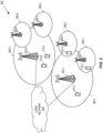
- FIG. 2 illustrates one example of a cellular communications network 200 according to some embodiments of the present disclosure.
- the cellular communications network 200 is a 5G NR-U network.
- the cellular communications network 200 includes base stations 202-1 and 202-2, which in 5G NR are referred to as gNBs, controlling corresponding macro cells 204-1 and 204-2.
- the base stations 202-1 and 202-2 are generally referred to herein collectively as base stations 202 and individually as base station 202.
- the macro cells 204-1 and 204-2 are generally referred to herein collectively as macro cells 204 and individually as macro cell 204.
- the cellular communications network 200 may also include a number of low power nodes 206-1 through 206-4 controlling corresponding small cells 208-1 through 208-4.
- the low power nodes 206-1 through 206-4 can be small base stations (such as pico or femto base stations) or Remote Radio Heads (RRHs), or the like.
- RRHs Remote Radio Heads
- one or more of the small cells 208-1 through 208-4 may alternatively be provided by the base stations 202.
- the low power nodes 206-1 through 206-4 are generally referred to herein collectively as low power nodes 206 and individually as low power node 206.
- the small cells 208-1 through 208-4 are generally referred to herein collectively as small cells 208 and individually as small cell 208.
- the base stations 202 (and optionally the low power nodes 206) are connected to a core network 210.
- the base stations 202 and the low power nodes 206 provide service to wireless devices 212-1 through 212-5 in the corresponding cells 204 and 208.
- the wireless devices 212-1 through 212-5 are generally referred to herein collectively as wireless devices 212 and individually as wireless device 212.
- the wireless devices 212 are also sometimes referred to herein as UEs.
- Embodiment #1 In this embodiment, a method of determining and signaling the RA for NR-U uplink transmissions to support partial interlace scheduling is performed, in which the RA information includes:
- a PRB unit often includes 12 subcarriers but could also include less or more than 12 subcarriers.
- an interlace that is not indicated as partially allocated in the RA information is implicitly understood as fully allocated (non-shared) and the scheduled UE can transmit in all PRBs of that interlace.
- the RA information may include a single set of indicator(s) of allocated interlace(s), where the allocated interlace(s) may be partially or fully allocated.
- the UE is able to determine that an allocated interlace is partially allocated if corresponding indictor(s) of one or more allocated PRBs in the allocated interlace is also included in the RA information.
- the indicator(s) of the partially allocated interlace(s) may or may not, by itself, indicate to the UE that the allocated interlace(s) is partially allocated.
- separate indicators may be included in the RA information for fully allocated interlaces and partially allocated interlaces.
- a common indicator(s) is included in the RA information for both fully and partially allocated interlaces, where the UE is then able to determine which allocated interlace(s) is(are) partially allocated by determining whether indicator(s) of allocated PRB(s) for the allocated interlaces is(are) also included in the RA information.
- the indicator of which interlaces are allocated can be any one of the following.
- the indicator(s) of which interlaces are partially allocated can be one of the following.
- the indicators can be separately encoded or a subset of them can be jointly encoded.
- Embodiment #2 In this embodiment, the PRB indicator of the allocated PRB(s) in an interlace that is partially allocated can be defined using RA type 0 as for NR (see 3GPP Technical Specification (TS) 38.214 V15.3.0) with the following modifications:
- Embodiment #3 In this embodiment, the PRB indicator of the allocated PRB(s) in an interlace that is partially allocated can be defined using RA type 1 as for NR (see 3GPP TS 38.214 V15.3.0) with the following modifications:
- Embodiment #4 In this embodiment, the PRB indicator of the allocated PRB(s) in an interlace that is partially allocated can be defined using RA type 1 as for NR (see 3GPP TS 38.214 V15.3.0) with the following modifications:
- Embodiment #5 In this embodiment, the PRB indicator of the allocated PRB(s) in an interlace that is partially allocated indexes a row of a predefined table, where different rows in the predefined table contain different allocations of PRBs within the interlace.
- Embodiment #6 In this embodiment, if multiple interlaces are partially allocated, the PRB indicators of the partially allocated interlaces can be arranged according to a predefined order (e.g., in increasing order of interlace index) so that the UEs can determine which PRB indicator corresponds to which partially allocated interlace.
- a predefined order e.g., in increasing order of interlace index
- Embodiment #7 In this embodiment, in systems with wideband operations consisting of a number of sub-bands, if the type 1 based PRB indicator in Embodiment #3 is used, the UEs may puncture (i.e., exclude) some PRBs in the guard band between sub-bands or channels even if those PRBs are scheduled by the gNB.
- Embodiment #8 In this embodiment, in systems with wideband operations consisting of a number of sub-bands, if the RA signaling is designed per sub-band, an additional sub-band bitmap could be included in the RA information to schedule multiple sub-bands.
- Embodiment #9 the RA within an interlace consists of a number of Virtual Resource Blocks (VRBs). Either a full or partial interlace allocation consists of a predefined mapping from VRBs to PRBs. As one non-limiting example, the VRB-to-PRB mapping can be an interleaved mapping. The PRB indicator for the corresponding interlace thus indicates which VRBs are allocated.
- VRBs Virtual Resource Blocks
- Figure 3 illustrates the operation of a network node (e.g., a base station 202) and a wireless device (e.g., a wireless device 212) in accordance with at least some aspects of Embodiments #1 through Embodiment #9 described above.
- the network node is a base station 202
- the wireless device is a wireless device 212.
- the base station 202 transmits, to the wireless device 212, an RA for an uplink transmission in unlicensed spectrum using allocated resources including resources in one or more partially allocated interlaces (step 300).
- the RA is an RA for an uplink transmission by the wireless device 212 in an NR-U cell.
- the RA is included in Downlink Control Information (DCI) transmitted on a Physical Downlink Control Channel (PDCCH).
- DCI Downlink Control Information
- the RA includes RA information including an indicator(s) of a partially allocated interlace(s) and a PRB indicator(s) of the PRB(s) in the partially allocated interlace(s) that indicates the PRB(s) within the partially allocated interlace(s) that is(are) allocated for the wireless device 212.
- the RA information may include an indicator(s) of an allocated interlace(s), if any, that is fully, rather than partially, allocated for the wireless device 212. Additional details regarding the RA information are provided above and, as such, are not repeated here.
- the wireless device 212 receives the RA and performs the uplink transmission in accordance with the RA (step 302). Thus, with respect to the partially allocated interlace(s), the wireless device 212 performs the uplink transmission using the indicated PRB(s) in the partially allocated interlace(s), in accordance with the RA information.
- FIG. 4 is a schematic block diagram of a radio access node 400 according to some embodiments of the present disclosure.
- the radio access node 400 may be, for example, a base station 202 or 206.
- the radio access node 400 includes a control system 402 that includes one or more processors 404 (e.g., Central Processing Units (CPUs), Application Specific Integrated Circuits (ASICs), Field Programmable Gate Arrays (FPGAs), and/or the like), memory 406, and a network interface 408.
- the one or more processors 404 are also referred to herein as processing circuitry.
- the radio access node 400 includes one or more radio units 410 that each includes one or more transmitters 412 and one or more receivers 414 coupled to one or more antennas 416.
- the radio units 410 may be referred to or be part of radio interface circuitry.
- the radio unit(s) 410 is external to the control system 402 and connected to the control system 402 via, e.g., a wired connection (e.g., an optical cable).
- the radio unit(s) 410 and potentially the antenna(s) 416 are integrated together with the control system 402.
- the one or more processors 404 operate to provide one or more functions of a radio access node 400 as described herein (e.g., one or more functions of a network node or base station 202 as described above).
- the function(s) are implemented in software that is stored, e.g., in the memory 406 and executed by the one or more processors 404.
- FIG. 5 is a schematic block diagram that illustrates a virtualized embodiment of the radio access node 400 according to some embodiments of the present disclosure. This discussion is equally applicable to other types of network nodes. Further, other types of network nodes may have similar virtualized architectures.
- a "virtualized" radio access node is an implementation of the radio access node 400 in which at least a portion of the functionality of the radio access node 400 is implemented as a virtual component(s) (e.g., via a virtual machine(s) executing on a physical processing node(s) in a network(s)).
- the radio access node 400 includes the control system 402 that includes the one or more processors 404 (e.g., CPUs, ASICs, FPGAs, and/or the like), the memory 406, and the network interface 408 and the one or more radio units 410 that each includes the one or more transmitters 412 and the one or more receivers 414 coupled to the one or more antennas 416, as described above.
- the control system 402 is connected to the radio unit(s) 410 via, for example, an optical cable or the like.
- the control system 402 is connected to one or more processing nodes 500 coupled to or included as part of a network(s) 502 via the network interface 408.
- Each processing node 500 includes one or more processors 504 (e.g., CPUs, ASICs, FPGAs, and/or the like), memory 506, and a network interface 508.
- functions 510 of the radio access node 400 described herein are implemented at the one or more processing nodes 500 or distributed across the control system 402 and the one or more processing nodes 500 in any desired manner.
- some or all of the functions 510 of the radio access node 400 described herein are implemented as virtual components executed by one or more virtual machines implemented in a virtual environment(s) hosted by the processing node(s) 500.
- additional signaling or communication between the processing node(s) 500 and the control system 402 is used in order to carry out at least some of the desired functions 510.
- the control system 402 may not be included, in which case the radio unit(s) 410 communicate directly with the processing node(s) 500 via an appropriate network interface(s).
- a computer program including instructions which, when executed by at least one processor, causes the at least one processor to carry out the functionality of radio access node 400 or a node (e.g., a processing node 500) implementing one or more of the functions 510 of the radio access node 400 (e.g., one or more functions of a network node or base station 202 as described above) in a virtual environment according to any of the embodiments described herein is provided.
- a carrier comprising the aforementioned computer program product is provided.
- the carrier is one of an electronic signal, an optical signal, a radio signal, or a computer readable storage medium (e.g., a non-transitory computer readable medium such as memory).
- FIG 6 is a schematic block diagram of the radio access node 400 according to some other embodiments of the present disclosure.
- the radio access node 400 includes one or more modules 600, each of which is implemented in software.
- the module(s) 600 provide the functionality of the radio access node 400 described herein (e.g., one or more functions of a network node or base station 202 as described above). This discussion is equally applicable to the processing node 500 of Figure 5 where the modules 600 may be implemented at one of the processing nodes 500 or distributed across multiple processing nodes 500 and/or distributed across the processing node(s) 500 and the control system 402.
- FIG. 7 is a schematic block diagram of a UE 700 according to some embodiments of the present disclosure.
- the UE 700 includes one or more processors 702 (e.g., CPUs, ASICs, FPGAs, and/or the like), memory 704, and one or more transceivers 706 each including one or more transmitters 708 and one or more receivers 710 coupled to one or more antennas 712.
- the transceiver(s) 706 includes radio-front end circuitry connected to the antenna(s) 712 that is configured to condition signals communicated between the antenna(s) 712 and the processor(s) 702, as will be appreciated by on of ordinary skill in the art.
- the processors 702 are also referred to herein as processing circuitry.
- the transceivers 706 are also referred to herein as radio circuitry.
- the functionality of the UE 700 described above e.g., one or more functions of a UE or wireless device 212 as described above
- the UE 700 may include additional components not illustrated in Figure 7 such as, e.g., one or more user interface components (e.g., an input/output interface including a display, buttons, a touch screen, a microphone, a speaker(s), and/or the like and/or any other components for allowing input of information into the UE 700 and/or allowing output of information from the UE 700), a power supply (e.g., a battery and associated power circuitry), etc.
- user interface components e.g., an input/output interface including a display, buttons, a touch screen, a microphone, a speaker(s), and/or the like and/or any other components for allowing input of information into the UE 700 and/or allowing output of information from the UE 700
- a power supply e.g., a battery and associated power circuitry
- a computer program including instructions which, when executed by at least one processor, causes the at least one processor to carry out the functionality of the UE 700 according to any of the embodiments described herein (e.g., one or more functions of a UE or wireless device 212 as described above) is provided.
- a carrier comprising the aforementioned computer program product is provided.
- the carrier is one of an electronic signal, an optical signal, a radio signal, or a computer readable storage medium (e.g., a non-transitory computer readable medium such as memory).
- FIG 8 is a schematic block diagram of the UE 700 according to some other embodiments of the present disclosure.
- the UE 700 includes one or more modules 800, each of which is implemented in software.
- the module(s) 800 provide the functionality of the UE 700 described herein (e.g., one or more functions of a UE or wireless device 212 as described above).
- a communication system includes a telecommunication network 900, such as a 3GPP-type cellular network, which comprises an access network 902, such as a RAN, and a core network 904.
- the access network 902 comprises a plurality of base stations 906A, 906B, 906C, such as Node Bs, eNBs, gNBs, or other types of wireless Access Points (APs), each defining a corresponding coverage area 908A, 908B, 908C.
- Each base station 906A, 906B, 906C is connectable to the core network 904 over a wired or wireless connection 910.
- a first UE 912 located in coverage area 908C is configured to wirelessly connect to, or be paged by, the corresponding base station 906C.
- a second UE 914 in coverage area 908A is wirelessly connectable to the corresponding base station 906A. While a plurality of UEs 912, 914 are illustrated in this example, the disclosed embodiments are equally applicable to a situation where a sole UE is in the coverage area or where a sole UE is connecting to the corresponding base station 906.
- the telecommunication network 900 is itself connected to a host computer 916, which may be embodied in the hardware and/or software of a standalone server, a cloud-implemented server, a distributed server, or as processing resources in a server farm.
- the host computer 916 may be under the ownership or control of a service provider, or may be operated by the service provider or on behalf of the service provider.
- Connections 918 and 920 between the telecommunication network 900 and the host computer 916 may extend directly from the core network 904 to the host computer 916 or may go via an optional intermediate network 922.
- the intermediate network 922 may be one of, or a combination of more than one of, a public, private, or hosted network; the intermediate network 922, if any, may be a backbone network or the Internet; in particular, the intermediate network 922 may comprise two or more sub-networks (not shown).
- the communication system of Figure 9 as a whole enables connectivity between the connected UEs 912, 914 and the host computer 916.
- the connectivity may be described as an Over-the-Top (OTT) connection 924.
- the host computer 916 and the connected UEs 912, 914 are configured to communicate data and/or signaling via the OTT connection 924, using the access network 902, the core network 904, any intermediate network 922, and possible further infrastructure (not shown) as intermediaries.
- the OTT connection 924 may be transparent in the sense that the participating communication devices through which the OTT connection 924 passes are unaware of routing of uplink and downlink communications.
- the base station 906 may not or need not be informed about the past routing of an incoming downlink communication with data originating from the host computer 916 to be forwarded (e.g., handed over) to a connected UE 912. Similarly, the base station 906 need not be aware of the future routing of an outgoing uplink communication originating from the UE 912 towards the host computer 916.
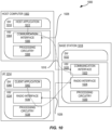
- a host computer 1002 comprises hardware 1004 including a communication interface 1006 configured to set up and maintain a wired or wireless connection with an interface of a different communication device of the communication system 1000.
- the host computer 1002 further comprises processing circuitry 1008, which may have storage and/or processing capabilities.
- the processing circuitry 1008 may comprise one or more programmable processors, ASICs, FPGAs, or combinations of these (not shown) adapted to execute instructions.
- the host computer 1002 further comprises software 1010, which is stored in or accessible by the host computer 1002 and executable by the processing circuitry 1008.
- the software 1010 includes a host application 1012.
- the host application 1012 may be operable to provide a service to a remote user, such as a UE 1014 connecting via an OTT connection 1016 terminating at the UE 1014 and the host computer 1002.
- the host application 1012 may provide user data which is transmitted using the OTT connection 1016.
- the communication system 1000 further includes a base station 1018 provided in a telecommunication system and comprising hardware 1020 enabling it to communicate with the host computer 1002 and with the UE 1014.
- the hardware 1020 may include a communication interface 1022 for setting up and maintaining a wired or wireless connection with an interface of a different communication device of the communication system 1000, as well as a radio interface 1024 for setting up and maintaining at least a wireless connection 1026 with the UE 1014 located in a coverage area (not shown in Figure 10 ) served by the base station 1018.
- the communication interface 1022 may be configured to facilitate a connection 1028 to the host computer 1002.
- connection 1028 may be direct or it may pass through a core network (not shown in Figure 10 ) of the telecommunication system and/or through one or more intermediate networks outside the telecommunication system.
- the hardware 1020 of the base station 1018 further includes processing circuitry 1030, which may comprise one or more programmable processors, ASICs, FPGAs, or combinations of these (not shown) adapted to execute instructions.
- the base station 1018 further has software 1032 stored internally or accessible via an external connection.
- the communication system 1000 further includes the UE 1014 already referred to.
- the UE's 1014 hardware 1034 may include a radio interface 1036 configured to set up and maintain a wireless connection 1026 with a base station serving a coverage area in which the UE 1014 is currently located.
- the hardware 1034 of the UE 1014 further includes processing circuitry 1038, which may comprise one or more programmable processors, ASICs, FPGAs, or combinations of these (not shown) adapted to execute instructions.
- the UE 1014 further comprises software 1040, which is stored in or accessible by the UE 1014 and executable by the processing circuitry 1038.
- the software 1040 includes a client application 1042.
- the client application 1042 may be operable to provide a service to a human or non-human user via the UE 1014, with the support of the host computer 1002.
- the executing host application 1012 may communicate with the executing client application 1042 via the OTT connection 1016 terminating at the UE 1014 and the host computer 1002.
- the client application 1042 may receive request data from the host application 1012 and provide user data in response to the request data.
- the OTT connection 1016 may transfer both the request data and the user data.
- the client application 1042 may interact with the user to generate the user data that it provides.
- the host computer 1002, the base station 1018, and the UE 1014 illustrated in Figure 10 may be similar or identical to the host computer 916, one of the base stations 906A, 906B, 906C, and one of the UEs 912, 914 of Figure 9 , respectively.
- the inner workings of these entities may be as shown in Figure 10 and independently, the surrounding network topology may be that of Figure 9 .
- the OTT connection 1016 has been drawn abstractly to illustrate the communication between the host computer 1002 and the UE 1014 via the base station 1018 without explicit reference to any intermediary devices and the precise routing of messages via these devices.
- the network infrastructure may determine the routing, which may be configured to hide from the UE 1014 or from the service provider operating the host computer 1002, or both. While the OTT connection 1016 is active, the network infrastructure may further take decisions by which it dynamically changes the routing (e.g., on the basis of load balancing consideration or reconfiguration of the network).
- the wireless connection 1026 between the UE 1014 and the base station 1018 is in accordance with the teachings of the embodiments described throughout this disclosure.
- One or more of the various embodiments improve the performance of OTT services provided to the UE 1014 using the OTT connection 1016, in which the wireless connection 1026 forms the last segment. More precisely, the teachings of these embodiments may improve the, e.g. data rate, latency, and/or power consumption and thereby provide benefits such as, e.g., reduced user waiting time, relaxed restriction on file size, better responsiveness, and/or extended battery lifetime.
- a measurement procedure may be provided for the purpose of monitoring data rate, latency, and other factors on which the one or more embodiments improve.
- the measurement procedure and/or the network functionality for reconfiguring the OTT connection 1016 may be implemented in the software 1010 and the hardware 1004 of the host computer 1002 or in the software 1040 and the hardware 1034 of the UE 1014, or both.
- sensors may be deployed in or in association with communication devices through which the OTT connection 1016 passes; the sensors may participate in the measurement procedure by supplying values of the monitored quantities exemplified above, or supplying values of other physical quantities from which the software 1010, 1040 may compute or estimate the monitored quantities.
- the reconfiguring of the OTT connection 1016 may include message format, retransmission settings, preferred routing, etc.; the reconfiguring need not affect the base station 1018, and it may be unknown or imperceptible to the base station 1018. Such procedures and functionalities may be known and practiced in the art.
- measurements may involve proprietary UE signaling facilitating the host computer 1002's measurements of throughput, propagation times, latency, and the like. The measurements may be implemented in that the software 1010 and 1040 causes messages to be transmitted, in particular empty or 'dummy' messages, using the OTT connection 1016 while it monitors propagation times, errors, etc.
- FIG 11 is a flowchart illustrating a method implemented in a communication system, in accordance with one embodiment.
- the communication system includes a host computer, a base station, and a UE which may be those described with reference to Figures 9 and 10 .
- the UE receives input data provided by the host computer. Additionally or alternatively, in step 1102, the UE provides user data.
- sub-step 1104 (which may be optional) of step 1100, the UE provides the user data by executing a client application.
- sub-step 1106 (which may be optional) of step 1102
- the UE executes a client application which provides the user data in reaction to the received input data provided by the host computer.
- the executed client application may further consider user input received from the user.
- the UE initiates, in sub-step 1108 (which may be optional), transmission of the user data to the host computer.
- step 1110 of the method the host computer receives the user data transmitted from the UE, in accordance with the teachings of the embodiments described throughout this disclosure.
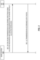
- FIG. 12 is a flowchart illustrating a method implemented in a communication system, in accordance with one embodiment.
- the communication system includes a host computer, a base station, and a UE which may be those described with reference to Figures 9 and 10 .
- the base station receives user data from the UE.
- the base station initiates transmission of the received user data to the host computer.
- the host computer receives the user data carried in the transmission initiated by the base station.
- any appropriate steps, methods, features, functions, or benefits disclosed herein may be performed through one or more functional units or modules of one or more virtual apparatuses.
- Each virtual apparatus may comprise a number of these functional units.
- These functional units may be implemented via processing circuitry, which may include one or more microprocessor or microcontrollers, as well as other digital hardware, which may include Digital Signal Processor (DSPs), special-purpose digital logic, and the like.
- the processing circuitry may be configured to execute program code stored in memory, which may include one or several types of memory such as Read Only Memory (ROM), Random Access Memory (RAM), cache memory, flash memory devices, optical storage devices, etc.
- Program code stored in memory includes program instructions for executing one or more telecommunications and/or data communications protocols as well as instructions for carrying out one or more of the techniques described herein.
- the processing circuitry may be used to cause the respective functional unit to perform corresponding functions according one or more embodiments of the present disclosure.
Landscapes
- Engineering & Computer Science (AREA)
- Computer Networks & Wireless Communication (AREA)
- Signal Processing (AREA)
- Mobile Radio Communication Systems (AREA)
Claims (15)
- Verfahren, das durch eine drahtlose Vorrichtung (212) durchgeführt wird, wobei das Verfahren Folgendes umfasst:Empfangen (300) einer Ressourcenzuweisung für eine Uplink-Übertragung, die Ressourcen in einer oder mehreren teilweise zugewiesenen Zwischenzeilen zuweist; undDurchführen (302) einer Uplink-Übertragung an zugewiesenen Ressourcen in der einen oder den mehreren teilweise zugewiesenen Zwischenzeilen gemäß der Ressourcenzuweisung; wobei die Ressourcenzuweisung Folgendes umfasst:Informationen, welche die eine oder die mehreren teilweise zugewiesenen Zwischenzeilen angeben; undbeliebige der Folgenden:Informationen, die einen oder mehrere physische Ressourcenblöcke innerhalb der einen oder der mehreren teilweise zugewiesenen Zwischenzeilen angeben, die für die Uplink-Übertragung von der drahtlosen Vorrichtung (212) zugewiesen sind, undfür jede teilweise zugewiesene Zwischenzeile der einen oder der mehreren teilweise zugewiesenen Zwischenzeilen, Informationen, die einen oder mehrere physische Ressourcenblöcke innerhalb der teilweise zugewiesenen Zwischenzeile angeben, die für die Uplink-Übertragung von der drahtlosen Vorrichtung (212) zugewiesen sind;dadurch gekennzeichnet, dass die Informationen, welche den einen oder die mehreren physischen Ressourcenblöcke angeben, unter Verwendung eines modifizierten New-Radio-(NR-)Resource-Allocation-(RA-)Typ-1-Ressourcenzuweisungsschemas definiert sind.
- Verfahren nach Anspruch 1, wobei die Uplink-Übertragung in einem drahtlosen Kommunikationsnetz mit Breitbandvorgängen erfolgt, das eine Anzahl von Teilbändern umfasst, und der Start und die Länge des einen oder der mehreren Teilbänder durch das modifizierte NR-RA-Typ-1-Ressourcenzuweisungsschema angegeben werden.
- Verfahren nach Anspruch 1, wobei die Informationen, welche den einen oder die mehreren physischen Ressourcenblöcke für jede teilweise zugewiesene Zwischenzeile angeben, gemeinsame Informationen sind, die den einen oder die mehreren physischen Ressourcenblöcke für jede teilweise zugewiesene Zwischenzeile angeben.
- Verfahren nach einem der Ansprüche 1 bis 3, wobei die Informationen, welche die eine oder die mehreren teilweise zugewiesenen Zwischenzeilen angeben, eine Bitmap einer Länge umfassen, die einer Anzahl von Zwischenzeilen entspricht, die zugewiesen werden können, wobei Bits in der Bitmap angeben, welche Zwischenzeilen teilweise zugewiesen sind.
- Verfahren nach einem der Ansprüche 1 bis 3, wobei die Informationen, welche die eine oder die mehreren teilweise zugewiesenen Zwischenzeilen angeben, eine Bit-Sequenz umfassen, die eine vordefinierte Kombination von Zwischenzeilen abbildet, die teilweise zugewiesen sind.
- Verfahren nach einem der Ansprüche 1 bis 5, wobei sich die Uplink-Übertragung in einem drahtlosen Kommunikationsnetz mit Breitbandvorgängen befindet, das aus einer Anzahl von Teilbändern besteht, und die drahtlose Vorrichtung (212) einen physischen Ressourcenblock/physische Ressourcenblöcke in einem Schutzband zwischen Teilbändern oder Kanälen ausschließt.
- Drahtlose Vorrichtung (212) für ein zellulares Kommunikationssystem (200), wobei die drahtlose Vorrichtung (212) zu Folgendem ausgelegt ist:Empfangen (300) einer Ressourcenzuweisung für eine Uplink-Übertragung, die Ressourcen in einer oder mehreren teilweise zugewiesenen Zwischenzeilen zuweist; undDurchführen (302) einer Uplink-Übertragung an den zugewiesenen Ressourcen in der einen oder den mehreren teilweise zugewiesenen Zwischenzeilen gemäß der Ressourcenzuweisung; wobei die Ressourcenzuweisung Folgendes umfasst:Informationen, welche die eine oder die mehreren teilweise zugewiesenen Zwischenzeilen angeben; undbeliebige der Folgenden:Informationen, die einen oder mehrere physische Ressourcenblöcke innerhalb der einen oder der mehreren teilweise zugewiesenen Zwischenzeilen angeben, die für die Uplink-Übertragung von der drahtlosen Vorrichtung (212) zugewiesen sind, undfür jede teilweise zugewiesene Zwischenzeile der einen oder der mehreren teilweise zugewiesenen Zwischenzeilen, Informationen, die einen oder mehrere physische Ressourcenblöcke innerhalb der teilweise zugewiesenen Zwischenzeile angeben, die für die Uplink-Übertragung von der drahtlosen Vorrichtung (212) zugewiesen sind;dadurch gekennzeichnet, dass die Informationen, welche den einen oder die mehreren physischen Ressourcenblöcke angeben, unter Verwendung eines modifizierten New-Radio-(NR-)Resource-Allocation-(RA-)Typ-1-Ressourcenzuweisungsschemas definiert sind.
- Drahtlose Vorrichtung (212) nach Anspruch 7, wobei die drahtlose Vorrichtung (212) ferner dazu ausgelegt ist, das Verfahren nach einem der Ansprüche 2 bis 6 durchzuführen.
- Verfahren, das durch eine Basisstation (202) durchgeführt wird, umfassend:
Übertragen (300), an eine drahtlose Vorrichtung (212), einer Ressourcenzuweisung für eine Uplink-Übertragung, die Ressourcen in einer oder mehreren teilweise zugewiesenen Zwischenzeilen zuweist; wobei die Ressourcenzuweisung Folgendes umfasst:Informationen, welche die eine oder die mehreren teilweise zugewiesenen Zwischenzeilen angeben; undbeliebige der Folgenden:Informationen, die einen oder mehrere physische Ressourcenblöcke innerhalb der einen oder der mehreren teilweise zugewiesenen Zwischenzeilen angeben, die für die Uplink-Übertragung von der drahtlosen Vorrichtung (212) zugewiesen sind, undfür jede teilweise zugewiesene Zwischenzeile der einen oder der mehreren teilweise zugewiesenen Zwischenzeilen, Informationen, die einen oder mehrere physische Ressourcenblöcke innerhalb der teilweise zugewiesenen Zwischenzeile angeben, die für die Uplink-Übertragung von der drahtlosen Vorrichtung (212) zugewiesen sind;dadurch gekennzeichnet, dass die Informationen, welche den einen oder die mehreren physischen Ressourcenblöcke angeben, unter Verwendung eines modifizierten New-Radio-(NR-)Resource-Allocation-(RA-)Typ-1-Ressourcenzuweisungsschemas definiert sind. - Verfahren nach Anspruch 9, wobei die Uplink-Übertragung in einem drahtlosen Kommunikationsnetz mit Breitbandvorgängen erfolgt, das eine Anzahl von Teilbändern umfasst, und der Start und die Länge des einen oder der mehreren Teilbänder durch das modifizierte NR-RA-Typ-1-Ressourcenzuweisungsschema angegeben werden.
- Verfahren nach Anspruch 9, wobei die Informationen, welche den einen oder die mehreren physischen Ressourcenblöcke für jede teilweise zugewiesene Zwischenzeile angeben, gemeinsame Informationen sind, die den einen oder die mehreren physischen Ressourcenblöcke für jede teilweise zugewiesene Zwischenzeile angeben.
- Verfahren nach einem der Ansprüche 9 bis 11, wobei die Informationen, welche die eine oder die mehreren teilweise zugewiesenen Zwischenzeilen angeben, eine Bitmap einer Länge umfassen, die einer Anzahl von Zwischenzeilen entspricht, die zugewiesen werden können, wobei Bits in der Bitmap angeben, welche Zwischenzeilen teilweise zugewiesen sind; oder wobei die Informationen, welche die eine oder die mehreren teilweise zugewiesenen Zwischenzeilen angeben, eine Bit-Sequenz umfassen, die eine vordefinierte Kombination von Zwischenzeilen abbildet, die teilweise zugewiesen sind.
- Verfahren nach einem der Ansprüche 9 bis 12, wobei sich die Uplink-Übertragung in einem drahtlosen Kommunikationsnetz mit Breitbandvorgängen befindet, das aus einer Anzahl von Teilbändern besteht, und die drahtlose Vorrichtung (212) einen physischen Ressourcenblock/physische Ressourcenblöcke in einem Schutzband zwischen Teilbändern oder Kanälen ausschließt.
- Basisstation (202) für ein zellulares Kommunikationssystem (200), wobei die Basisstation (202) zu Folgendem ausgelegt ist: Übertragen (300), an eine drahtlose Vorrichtung (212), einer Ressourcenzuweisung für eine Uplink-Übertragung, die Ressourcen in einer oder mehreren teilweise zugewiesenen Zwischenzeilen zuweist; wobei die Ressourcenzuweisung Folgendes umfasst:Informationen, welche die eine oder die mehreren teilweise zugewiesenen Zwischenzeilen angeben; undbeliebige der Folgenden:Informationen, die einen oder mehrere physische Ressourcenblöcke innerhalb der einen oder der mehreren teilweise zugewiesenen Zwischenzeilen angeben, die für die Uplink-Übertragung von der drahtlosen Vorrichtung (212) zugewiesen sind, undfür jede teilweise zugewiesene Zwischenzeile der einen oder der mehreren teilweise zugewiesenen Zwischenzeilen, Informationen, die einen oder mehrere physische Ressourcenblöcke innerhalb der teilweise zugewiesenen Zwischenzeile angeben, die für die Uplink-Übertragung von der drahtlosen Vorrichtung (212) zugewiesen sind;dadurch gekennzeichnet, dass die Informationen, welche den einen oder die mehreren physischen Ressourcenblöcke angeben, unter Verwendung eines modifizierten New-Radio-(NR-)Resource-Allocation-(RA-)Typ-1-Ressourcenzuweisungsschemas definiert sind.
- Basisstation (202) nach Anspruch 14, wobei die Basisstation (202) ferner dazu ausgelegt ist, das Verfahren nach einem der Ansprüche 10 bis 13 durchzuführen.
Applications Claiming Priority (2)
| Application Number | Priority Date | Filing Date | Title |
|---|---|---|---|
| US201962791431P | 2019-01-11 | 2019-01-11 | |
| PCT/EP2020/050192 WO2020144168A1 (en) | 2019-01-11 | 2020-01-07 | Resource allocation for uplink transmissions in unlicensed spectrum |
Publications (3)
| Publication Number | Publication Date |
|---|---|
| EP3909347A1 EP3909347A1 (de) | 2021-11-17 |
| EP3909347B1 true EP3909347B1 (de) | 2023-12-27 |
| EP3909347C0 EP3909347C0 (de) | 2023-12-27 |
Family
ID=69147707
Family Applications (1)
| Application Number | Title | Priority Date | Filing Date |
|---|---|---|---|
| EP20700252.8A Active EP3909347B1 (de) | 2019-01-11 | 2020-01-07 | Ressourcenzuweisung für uplink-übertragungen in unlizenziertem spektrum |
Country Status (6)
| Country | Link |
|---|---|
| US (2) | US12075432B2 (de) |
| EP (1) | EP3909347B1 (de) |
| JP (1) | JP7284273B2 (de) |
| CN (1) | CN113330797B (de) |
| BR (1) | BR112021012341A2 (de) |
| WO (1) | WO2020144168A1 (de) |
Families Citing this family (3)
| Publication number | Priority date | Publication date | Assignee | Title |
|---|---|---|---|---|
| KR20210121242A (ko) * | 2019-02-15 | 2021-10-07 | 애플 인크. | Nr-비면허에서의 물리적 업링크 채널에 대한 광대역 인터레이스 설계 |
| CN114342530A (zh) | 2019-07-03 | 2022-04-12 | 瑞典爱立信有限公司 | 针对交错传输的频域资源分配 |
| US12376114B2 (en) * | 2022-07-07 | 2025-07-29 | Qualcomm Incorporated | Frequency division multiplexing for uplink shared channel transmissions with interlaced resource block allocation |
Family Cites Families (26)
| Publication number | Priority date | Publication date | Assignee | Title |
|---|---|---|---|---|
| KR20110018107A (ko) * | 2009-08-17 | 2011-02-23 | 삼성전자주식회사 | 레지듀얼 신호 인코딩 및 디코딩 방법 및 장치 |
| US9578625B2 (en) * | 2012-02-28 | 2017-02-21 | Lg Electronics Inc. | Method and apparatus for allocating resources in wireless communication system |
| US10057027B2 (en) * | 2015-05-07 | 2018-08-21 | Electronics And Telecommunications Research Institute | Method and apparatus for receiving reference signal |
| WO2017052193A1 (ko) | 2015-09-21 | 2017-03-30 | 엘지전자 주식회사 | 비면허 대역에서 데이터를 송수신하는 방법 및 이를 위한 장치 |
| US10412755B2 (en) * | 2016-03-25 | 2019-09-10 | Qualcomm Incorporated | Techniques for configuring uplink transmissions in a shared radio frequency spectrum band |
| US10356761B2 (en) | 2016-03-30 | 2019-07-16 | Qualcomm Incorporated | Techniques for configuring uplink control channel transmissions in a shared radio frequency spectrum band |
| JP6205007B1 (ja) | 2016-03-31 | 2017-09-27 | 株式会社Nttドコモ | ユーザ端末、無線基地局及び無線通信方法 |
| GB2548922B (en) | 2016-04-01 | 2018-09-12 | Tcl Communication Ltd | Resource block allocation for uplink communications |
| WO2017214621A1 (en) | 2016-06-11 | 2017-12-14 | Ofinno Technologies, Llc | Listen before talk procedure in a wireless device and wireless network |
| WO2018031066A1 (en) | 2016-08-10 | 2018-02-15 | Intel IP Corporation | Resource allocation indication for physical uplink control channel (pucch) |
| US10506596B2 (en) * | 2016-10-28 | 2019-12-10 | Qualcomm Incorporated | Coexistence of interleaved and contiguous uplink transmissions |
| US10362574B2 (en) * | 2016-11-18 | 2019-07-23 | Qualcomm Incorporated | Uplink resource allocation techniques for shared radio frequency spectrum |
| CN108282870B (zh) * | 2017-01-06 | 2021-04-20 | 华为技术有限公司 | 一种资源指示方法、用户设备及网络设备 |
| CN108366424B (zh) | 2017-01-26 | 2021-10-26 | 华为技术有限公司 | 一种资源分配方法、相关设备及系统 |
| US10595217B2 (en) * | 2017-02-13 | 2020-03-17 | Qualcomm Incorporated | Flexible interleaving for wireless communications |
| CN112737753B (zh) | 2017-06-09 | 2022-02-15 | 华为技术有限公司 | 一种信号传输方法、相关设备及系统 |
| WO2019216910A1 (en) | 2018-05-11 | 2019-11-14 | Nokia Technologies Oy | Wideband nr-u operation compatible with narrowband interlace structures |
| US12127202B2 (en) | 2018-08-09 | 2024-10-22 | Lg Electronics Inc. | Method for transmitting or receiving uplink signal between terminal and base station in wireless communication system supporting unlicensed band, and apparatus for supporting same |
| US11905256B2 (en) | 2018-11-01 | 2024-02-20 | Flexsys America L.P. | Triazinanes and methods of making them |
| EP3697154A1 (de) * | 2019-02-14 | 2020-08-19 | Panasonic Intellectual Property Corporation of America | Sendeempfängervorrichtung und planungsvorrichtung |
| BR112021013902A2 (pt) | 2019-02-14 | 2021-09-21 | Panasonic Intellectual Property Corporation Of America | Dispositivo de transmissão, dispositivo de recepção, método de transmissão e método de recepção |
| CN110536418A (zh) | 2019-03-13 | 2019-12-03 | 中兴通讯股份有限公司 | 数据传输方法、装置、用户设备、基站及存储介质 |
| CN111278127B (zh) | 2019-04-03 | 2022-08-02 | 维沃移动通信有限公司 | 一种频域资源分配方法、终端和网络设备 |
| WO2020223667A1 (en) | 2019-05-02 | 2020-11-05 | Apple Inc. | Enhancements of frequency domain resource allocation schemes for physical uplink shared channel in nr-unlicensed |
| CN114342530A (zh) | 2019-07-03 | 2022-04-12 | 瑞典爱立信有限公司 | 针对交错传输的频域资源分配 |
| US12200763B2 (en) | 2019-08-09 | 2025-01-14 | Sharp Kabushiki Kaisha | User equipments, base stations, and methods |
-
2020
- 2020-01-07 BR BR112021012341-5A patent/BR112021012341A2/pt unknown
- 2020-01-07 WO PCT/EP2020/050192 patent/WO2020144168A1/en not_active Ceased
- 2020-01-07 JP JP2021539404A patent/JP7284273B2/ja active Active
- 2020-01-07 EP EP20700252.8A patent/EP3909347B1/de active Active
- 2020-01-07 CN CN202080008567.7A patent/CN113330797B/zh active Active
- 2020-01-07 US US17/422,179 patent/US12075432B2/en active Active
-
2024
- 2024-05-14 US US18/663,689 patent/US12414132B2/en active Active
Also Published As
| Publication number | Publication date |
|---|---|
| CN113330797B (zh) | 2024-08-16 |
| JP2022516934A (ja) | 2022-03-03 |
| US20240414720A1 (en) | 2024-12-12 |
| WO2020144168A1 (en) | 2020-07-16 |
| EP3909347C0 (de) | 2023-12-27 |
| BR112021012341A2 (pt) | 2021-08-31 |
| US12075432B2 (en) | 2024-08-27 |
| US12414132B2 (en) | 2025-09-09 |
| EP3909347A1 (de) | 2021-11-17 |
| JP7284273B2 (ja) | 2023-05-30 |
| CN113330797A (zh) | 2021-08-31 |
| US20220086893A1 (en) | 2022-03-17 |
Similar Documents
| Publication | Publication Date | Title |
|---|---|---|
| EP3753196B1 (de) | Netzwerkgerät, terminalgerät und methoden darin | |
| US10959260B2 (en) | Time resources for new radio configured uplink (UL) | |
| US12238715B2 (en) | Method and apparatus for using indication information of time domain resource allocation | |
| US12414132B2 (en) | Resource allocation for uplink transmissions in unlicensed spectrum | |
| US12501320B2 (en) | Frequency domain resource allocation for interlaced transmission | |
| US20240064736A1 (en) | Method and apparatus for resource configuration for configured grant based transmission | |
| RU2742045C1 (ru) | Терминал, способ радиосвязи и базовая станция | |
| US20250286673A1 (en) | Network devices, terminal devices, and methods therein | |
| EP4515795A1 (de) | Referenzsignalkonfiguration für vollduplex-teilbandbetrieb | |
| WO2020024202A1 (en) | Dynamic adjustment of pdcch monitoring occasions | |
| US12588070B2 (en) | Physical random access channel (PRACH) configurations for subcarrier spacing (SCS) | |
| US20220377714A1 (en) | Physical resource block (prb) set availability indication | |
| CN117751651A (zh) | 终端、基站和通信方法 | |
| CN111771338B (zh) | 用于物理上行链路共享信道跳频分配的方法和装置 | |
| WO2020029675A1 (en) | Method and apparatus for sounding reference signal transmission | |
| JP7639831B2 (ja) | 端末、通信システム及び通信方法 | |
| CN117716771A (zh) | 终端和基站 | |
| CN121890228A (zh) | 用于多个载波的随机接入 |
Legal Events
| Date | Code | Title | Description |
|---|---|---|---|
| STAA | Information on the status of an ep patent application or granted ep patent |
Free format text: STATUS: UNKNOWN |
|
| STAA | Information on the status of an ep patent application or granted ep patent |
Free format text: STATUS: THE INTERNATIONAL PUBLICATION HAS BEEN MADE |
|
| PUAI | Public reference made under article 153(3) epc to a published international application that has entered the european phase |
Free format text: ORIGINAL CODE: 0009012 |
|
| STAA | Information on the status of an ep patent application or granted ep patent |
Free format text: STATUS: REQUEST FOR EXAMINATION WAS MADE |
|
| 17P | Request for examination filed |
Effective date: 20210621 |
|
| AK | Designated contracting states |
Kind code of ref document: A1 Designated state(s): AL AT BE BG CH CY CZ DE DK EE ES FI FR GB GR HR HU IE IS IT LI LT LU LV MC MK MT NL NO PL PT RO RS SE SI SK SM TR |
|
| DAV | Request for validation of the european patent (deleted) | ||
| DAX | Request for extension of the european patent (deleted) | ||
| REG | Reference to a national code |
Ref country code: DE Ref legal event code: R079 Free format text: PREVIOUS MAIN CLASS: H04W0072040000 Ipc: H04W0072230000 Ref country code: DE Ref legal event code: R079 Ref document number: 602020023352 Country of ref document: DE Free format text: PREVIOUS MAIN CLASS: H04W0072040000 Ipc: H04W0072230000 |
|
| RIC1 | Information provided on ipc code assigned before grant |
Ipc: H04W 16/14 20090101ALN20230619BHEP Ipc: H04W 72/23 20230101AFI20230619BHEP |
|
| GRAP | Despatch of communication of intention to grant a patent |
Free format text: ORIGINAL CODE: EPIDOSNIGR1 |
|
| STAA | Information on the status of an ep patent application or granted ep patent |
Free format text: STATUS: GRANT OF PATENT IS INTENDED |
|
| INTG | Intention to grant announced |
Effective date: 20230810 |
|
| RIC1 | Information provided on ipc code assigned before grant |
Ipc: H04W 16/14 20090101ALN20230731BHEP Ipc: H04W 72/23 20230101AFI20230731BHEP |
|
| GRAS | Grant fee paid |
Free format text: ORIGINAL CODE: EPIDOSNIGR3 |
|
| GRAA | (expected) grant |
Free format text: ORIGINAL CODE: 0009210 |
|
| STAA | Information on the status of an ep patent application or granted ep patent |
Free format text: STATUS: THE PATENT HAS BEEN GRANTED |
|
| AK | Designated contracting states |
Kind code of ref document: B1 Designated state(s): AL AT BE BG CH CY CZ DE DK EE ES FI FR GB GR HR HU IE IS IT LI LT LU LV MC MK MT NL NO PL PT RO RS SE SI SK SM TR |
|
| REG | Reference to a national code |
Ref country code: GB Ref legal event code: FG4D |
|
| REG | Reference to a national code |
Ref country code: CH Ref legal event code: EP |
|
| REG | Reference to a national code |
Ref country code: DE Ref legal event code: R096 Ref document number: 602020023352 Country of ref document: DE |
|
| REG | Reference to a national code |
Ref country code: IE Ref legal event code: FG4D |
|
| U01 | Request for unitary effect filed |
Effective date: 20240110 |
|
| U07 | Unitary effect registered |
Designated state(s): AT BE BG DE DK EE FI FR IT LT LU LV MT NL PT SE SI Effective date: 20240118 |
|
| U20 | Renewal fee for the european patent with unitary effect paid |
Year of fee payment: 5 Effective date: 20240125 |
|
| PG25 | Lapsed in a contracting state [announced via postgrant information from national office to epo] |
Ref country code: GR Free format text: LAPSE BECAUSE OF FAILURE TO SUBMIT A TRANSLATION OF THE DESCRIPTION OR TO PAY THE FEE WITHIN THE PRESCRIBED TIME-LIMIT Effective date: 20240328 |
|
| PG25 | Lapsed in a contracting state [announced via postgrant information from national office to epo] |
Ref country code: ES Free format text: LAPSE BECAUSE OF FAILURE TO SUBMIT A TRANSLATION OF THE DESCRIPTION OR TO PAY THE FEE WITHIN THE PRESCRIBED TIME-LIMIT Effective date: 20231227 |
|
| PG25 | Lapsed in a contracting state [announced via postgrant information from national office to epo] |
Ref country code: GR Free format text: LAPSE BECAUSE OF FAILURE TO SUBMIT A TRANSLATION OF THE DESCRIPTION OR TO PAY THE FEE WITHIN THE PRESCRIBED TIME-LIMIT Effective date: 20240328 Ref country code: ES Free format text: LAPSE BECAUSE OF FAILURE TO SUBMIT A TRANSLATION OF THE DESCRIPTION OR TO PAY THE FEE WITHIN THE PRESCRIBED TIME-LIMIT Effective date: 20231227 |
|
| PG25 | Lapsed in a contracting state [announced via postgrant information from national office to epo] |
Ref country code: RS Free format text: LAPSE BECAUSE OF FAILURE TO SUBMIT A TRANSLATION OF THE DESCRIPTION OR TO PAY THE FEE WITHIN THE PRESCRIBED TIME-LIMIT Effective date: 20231227 Ref country code: NO Free format text: LAPSE BECAUSE OF FAILURE TO SUBMIT A TRANSLATION OF THE DESCRIPTION OR TO PAY THE FEE WITHIN THE PRESCRIBED TIME-LIMIT Effective date: 20240327 Ref country code: HR Free format text: LAPSE BECAUSE OF FAILURE TO SUBMIT A TRANSLATION OF THE DESCRIPTION OR TO PAY THE FEE WITHIN THE PRESCRIBED TIME-LIMIT Effective date: 20231227 |
|
| PG25 | Lapsed in a contracting state [announced via postgrant information from national office to epo] |
Ref country code: IS Free format text: LAPSE BECAUSE OF FAILURE TO SUBMIT A TRANSLATION OF THE DESCRIPTION OR TO PAY THE FEE WITHIN THE PRESCRIBED TIME-LIMIT Effective date: 20240427 |
|
| PG25 | Lapsed in a contracting state [announced via postgrant information from national office to epo] |
Ref country code: CZ Free format text: LAPSE BECAUSE OF FAILURE TO SUBMIT A TRANSLATION OF THE DESCRIPTION OR TO PAY THE FEE WITHIN THE PRESCRIBED TIME-LIMIT Effective date: 20231227 |
|
| PG25 | Lapsed in a contracting state [announced via postgrant information from national office to epo] |
Ref country code: SK Free format text: LAPSE BECAUSE OF FAILURE TO SUBMIT A TRANSLATION OF THE DESCRIPTION OR TO PAY THE FEE WITHIN THE PRESCRIBED TIME-LIMIT Effective date: 20231227 |
|
| PG25 | Lapsed in a contracting state [announced via postgrant information from national office to epo] |
Ref country code: SM Free format text: LAPSE BECAUSE OF FAILURE TO SUBMIT A TRANSLATION OF THE DESCRIPTION OR TO PAY THE FEE WITHIN THE PRESCRIBED TIME-LIMIT Effective date: 20231227 Ref country code: SK Free format text: LAPSE BECAUSE OF FAILURE TO SUBMIT A TRANSLATION OF THE DESCRIPTION OR TO PAY THE FEE WITHIN THE PRESCRIBED TIME-LIMIT Effective date: 20231227 Ref country code: RO Free format text: LAPSE BECAUSE OF FAILURE TO SUBMIT A TRANSLATION OF THE DESCRIPTION OR TO PAY THE FEE WITHIN THE PRESCRIBED TIME-LIMIT Effective date: 20231227 Ref country code: IS Free format text: LAPSE BECAUSE OF FAILURE TO SUBMIT A TRANSLATION OF THE DESCRIPTION OR TO PAY THE FEE WITHIN THE PRESCRIBED TIME-LIMIT Effective date: 20240427 Ref country code: CZ Free format text: LAPSE BECAUSE OF FAILURE TO SUBMIT A TRANSLATION OF THE DESCRIPTION OR TO PAY THE FEE WITHIN THE PRESCRIBED TIME-LIMIT Effective date: 20231227 |
|
| PG25 | Lapsed in a contracting state [announced via postgrant information from national office to epo] |
Ref country code: PL Free format text: LAPSE BECAUSE OF FAILURE TO SUBMIT A TRANSLATION OF THE DESCRIPTION OR TO PAY THE FEE WITHIN THE PRESCRIBED TIME-LIMIT Effective date: 20231227 |
|
| PG25 | Lapsed in a contracting state [announced via postgrant information from national office to epo] |
Ref country code: PL Free format text: LAPSE BECAUSE OF FAILURE TO SUBMIT A TRANSLATION OF THE DESCRIPTION OR TO PAY THE FEE WITHIN THE PRESCRIBED TIME-LIMIT Effective date: 20231227 |
|
| REG | Reference to a national code |
Ref country code: CH Ref legal event code: PL |
|
| PG25 | Lapsed in a contracting state [announced via postgrant information from national office to epo] |
Ref country code: MC Free format text: LAPSE BECAUSE OF FAILURE TO SUBMIT A TRANSLATION OF THE DESCRIPTION OR TO PAY THE FEE WITHIN THE PRESCRIBED TIME-LIMIT Effective date: 20231227 |
|
| REG | Reference to a national code |
Ref country code: DE Ref legal event code: R097 Ref document number: 602020023352 Country of ref document: DE |
|
| PG25 | Lapsed in a contracting state [announced via postgrant information from national office to epo] |
Ref country code: CH Free format text: LAPSE BECAUSE OF NON-PAYMENT OF DUE FEES Effective date: 20240131 |
|
| PG25 | Lapsed in a contracting state [announced via postgrant information from national office to epo] |
Ref country code: CH Free format text: LAPSE BECAUSE OF NON-PAYMENT OF DUE FEES Effective date: 20240131 |
|
| PLBE | No opposition filed within time limit |
Free format text: ORIGINAL CODE: 0009261 |
|
| STAA | Information on the status of an ep patent application or granted ep patent |
Free format text: STATUS: NO OPPOSITION FILED WITHIN TIME LIMIT |
|
| 26N | No opposition filed |
Effective date: 20240930 |
|
| PG25 | Lapsed in a contracting state [announced via postgrant information from national office to epo] |
Ref country code: IE Free format text: LAPSE BECAUSE OF NON-PAYMENT OF DUE FEES Effective date: 20240107 |
|
| PG25 | Lapsed in a contracting state [announced via postgrant information from national office to epo] |
Ref country code: IE Free format text: LAPSE BECAUSE OF NON-PAYMENT OF DUE FEES Effective date: 20240107 |
|
| U20 | Renewal fee for the european patent with unitary effect paid |
Year of fee payment: 6 Effective date: 20250127 |
|
| PG25 | Lapsed in a contracting state [announced via postgrant information from national office to epo] |
Ref country code: CY Free format text: LAPSE BECAUSE OF FAILURE TO SUBMIT A TRANSLATION OF THE DESCRIPTION OR TO PAY THE FEE WITHIN THE PRESCRIBED TIME-LIMIT; INVALID AB INITIO Effective date: 20200107 |
|
| PG25 | Lapsed in a contracting state [announced via postgrant information from national office to epo] |
Ref country code: HU Free format text: LAPSE BECAUSE OF FAILURE TO SUBMIT A TRANSLATION OF THE DESCRIPTION OR TO PAY THE FEE WITHIN THE PRESCRIBED TIME-LIMIT; INVALID AB INITIO Effective date: 20200107 |
|
| PG25 | Lapsed in a contracting state [announced via postgrant information from national office to epo] |
Ref country code: TR Free format text: LAPSE BECAUSE OF FAILURE TO SUBMIT A TRANSLATION OF THE DESCRIPTION OR TO PAY THE FEE WITHIN THE PRESCRIBED TIME-LIMIT Effective date: 20231227 |
|
| U20 | Renewal fee for the european patent with unitary effect paid |
Year of fee payment: 7 Effective date: 20260127 |
|
| PGFP | Annual fee paid to national office [announced via postgrant information from national office to epo] |
Ref country code: GB Payment date: 20260127 Year of fee payment: 7 |