EP3908834B1 - Sensorized device for the analysis of a fluid by means of acoustic waves - Google Patents
Sensorized device for the analysis of a fluid by means of acoustic waves Download PDFInfo
- Publication number
- EP3908834B1 EP3908834B1 EP20704075.9A EP20704075A EP3908834B1 EP 3908834 B1 EP3908834 B1 EP 3908834B1 EP 20704075 A EP20704075 A EP 20704075A EP 3908834 B1 EP3908834 B1 EP 3908834B1
- Authority
- EP
- European Patent Office
- Prior art keywords
- fluid
- interdigital transducer
- surface acoustic
- acoustic wave
- emitting
- Prior art date
- Legal status (The legal status is an assumption and is not a legal conclusion. Google has not performed a legal analysis and makes no representation as to the accuracy of the status listed.)
- Active
Links
Images



Classifications
-
- G—PHYSICS
- G01—MEASURING; TESTING
- G01N—INVESTIGATING OR ANALYSING MATERIALS BY DETERMINING THEIR CHEMICAL OR PHYSICAL PROPERTIES
- G01N29/00—Investigating or analysing materials by the use of ultrasonic, sonic or infrasonic waves; Visualisation of the interior of objects by transmitting ultrasonic or sonic waves through the object
- G01N29/02—Analysing fluids
- G01N29/022—Fluid sensors based on microsensors, e.g. quartz crystal-microbalance [QCM], surface acoustic wave [SAW] devices, tuning forks, cantilevers, flexural plate wave [FPW] devices
-
- G—PHYSICS
- G01—MEASURING; TESTING
- G01N—INVESTIGATING OR ANALYSING MATERIALS BY DETERMINING THEIR CHEMICAL OR PHYSICAL PROPERTIES
- G01N29/00—Investigating or analysing materials by the use of ultrasonic, sonic or infrasonic waves; Visualisation of the interior of objects by transmitting ultrasonic or sonic waves through the object
- G01N29/02—Analysing fluids
- G01N29/036—Analysing fluids by measuring frequency or resonance of acoustic waves
-
- G—PHYSICS
- G01—MEASURING; TESTING
- G01N—INVESTIGATING OR ANALYSING MATERIALS BY DETERMINING THEIR CHEMICAL OR PHYSICAL PROPERTIES
- G01N29/00—Investigating or analysing materials by the use of ultrasonic, sonic or infrasonic waves; Visualisation of the interior of objects by transmitting ultrasonic or sonic waves through the object
- G01N29/22—Details, e.g. general constructional or apparatus details
- G01N29/222—Constructional or flow details for analysing fluids
-
- G—PHYSICS
- G01—MEASURING; TESTING
- G01N—INVESTIGATING OR ANALYSING MATERIALS BY DETERMINING THEIR CHEMICAL OR PHYSICAL PROPERTIES
- G01N2291/00—Indexing codes associated with group G01N29/00
- G01N2291/01—Indexing codes associated with the measuring variable
- G01N2291/014—Resonance or resonant frequency
-
- G—PHYSICS
- G01—MEASURING; TESTING
- G01N—INVESTIGATING OR ANALYSING MATERIALS BY DETERMINING THEIR CHEMICAL OR PHYSICAL PROPERTIES
- G01N2291/00—Indexing codes associated with group G01N29/00
- G01N2291/02—Indexing codes associated with the analysed material
- G01N2291/025—Change of phase or condition
- G01N2291/0255—(Bio)chemical reactions, e.g. on biosensors
-
- G—PHYSICS
- G01—MEASURING; TESTING
- G01N—INVESTIGATING OR ANALYSING MATERIALS BY DETERMINING THEIR CHEMICAL OR PHYSICAL PROPERTIES
- G01N2291/00—Indexing codes associated with group G01N29/00
- G01N2291/02—Indexing codes associated with the analysed material
- G01N2291/025—Change of phase or condition
- G01N2291/0256—Adsorption, desorption, surface mass change, e.g. on biosensors
-
- G—PHYSICS
- G01—MEASURING; TESTING
- G01N—INVESTIGATING OR ANALYSING MATERIALS BY DETERMINING THEIR CHEMICAL OR PHYSICAL PROPERTIES
- G01N2291/00—Indexing codes associated with group G01N29/00
- G01N2291/04—Wave modes and trajectories
- G01N2291/042—Wave modes
- G01N2291/0423—Surface waves, e.g. Rayleigh waves, Love waves
Definitions
- the present invention relates to the analysis of fluids and the detection of specific analytes of interest.
- the invention relates to the detection of these analytes by means of surface acoustic waves generated by nanostructured sensors.
- microfluidics that is the technology that allows the manipulation of biological and non-biological fluids on a micrometric scale
- the biosensor object of the article includes a piezoelectric substrate on which metal structures are produced capable of generating surface acoustic waves (SAWs), in particular of the Rayleigh type (R-SAWs), by applying radio frequency.
- SAWs surface acoustic waves
- biomarkers the molecules that see their concentration in the biological fluids of patients change can be indicators ("biomarkers") of damage or dysfunction of internal organs, even before more serious symptoms are observed.
- biomarkers the possibility of identifying the onset of cancers such as breast cancer, pancreatic cancer or prostate cancer is known thanks to the monitoring of specific biomarkers.
- the variation in the concentration of these biomarkers is often detectable only through complex laboratory analyses, especially in the early stages of the disease.
- US2006049714 describes a chemical acoustic wave sensor used to monitor the concentration of an analyte in a substance such as blood.
- This chemical sensor can comprise one or more interdigital transducers and a selective coating formed on a piezoelectric substrate. The coating and interdigital transducer are used to convert the electrical signal into surface waves.
- the device comprises an antenna suitable for receiving one or more input signals, which excite the acoustic device and produce an output signal related to the concentration of the analyte of interest.
- the identified resonance frequency or one of those identified, and evaluate whether, after the passage of the fluid, an electrical signal at that frequency still produces an acoustic wave having power equal to that previously detected.
- the variation of the resonance frequency is a function of the variation of the mass density of the external surface and, therefore, the concentration of the analytes present in the analysed fluid.
- the variation in mass density can be positive, in the event that the analytes bind to the molecular probe, or negative, in the event that the analytes cut the molecular probe.
- this solution allows, being completely electric and integrated on a chip, to have a considerably smaller footprint and greater practicality of use, making the device a fluid analysis laboratory easily transportable.
- said step of adsorbing a plurality of probe molecules is carried out on said or each emitting interdigital transducer and/or on said or each electrode reflector.
- the sensorized device also comprises an auxiliary interdigital transducer and, simultaneously or upstream of the step of conveying the fluid on the outer surface, a step is provided of transmission, by the auxiliary interdigital transducer, of a surface acoustic wave having frequency f t for introducing turbulence in the fluid.
- the frequencies f i of the n surface acoustic waves emitted by the emitting interdigital transducer are greater than 800 MHz
- the frequency f t emitted by the auxiliary interdigital transducer is less than 800 MHz .
- the sensorized device comprises at least two SAW sensors and a control unit and a step is also provided of comparing the surface acoustic waves reflected by the reflector electrodes of the at least two SAW sensors for reducing noise and determine with higher precision said or each resonance frequency f r .
- this solution allows to increase the accuracy of the analysis thanks to the differential measurement that acts as a filter on the response signal.
- the sensorized device comprises at least one microfluidic channel arranged to convey the fluid along a predetermined path on the outer surface, in order to contain the fluid in a minimum volume where it is carried out the analysis.
- This solution allows a reduced volume of fluid to be used compared to prior art devices, reducing consumption, as well as increasing the surface/volume ratio with a consequent increase in diagnostic performance, and therefore the possibility of significantly increasing the number of analyses performed on the same device.
- This solution allows to receive more than one signal simultaneously, being able to make a comparison that reduces the noise of the signal itself.
- a sensorized device for the detection of analytes within a fluid in accordance with claim 8 is claimed.
- the present invention therefore presents a device that can be fully integrated within a chip, capable of performing highly sensitive analyses with respect to traditional instruments, so as to allow the implementation of the aforementioned method.
- an auxiliary interdigital transducer is also provided arranged to emit a surface acoustic wave having frequency f t for introducing turbulence in the fluid, and where the frequencies f i of the n surface acoustic waves emitted by the emitting interdigital transducer are greater than 800 MHz , whereas the frequency f t emitted by the auxiliary interdigital transducer is less than 800 MHz .
- At least two SAW sensors and a control unit are also provided arranged to compare the surface acoustic waves reflected by the reflector electrodes of the at least two SAW sensors for reducing noise.
- At least one microfluidic channel is also provided arranged to convey the fluid along a predetermined path on the outer surface, in order to contain the fluid in a minimum volume where it is carried out said analysis.
- said or each SAW sensor is a R-SAW sensor adapted to generate surface acoustic waves of Rayleigh type [Rayleigh Surface Acoustic Wave].
- the piezoelectric portion of the substrate is made of Lithium niobate [LN].
- This material allows the transmission of the R-SAW surface acoustic waves at least in a direction.
- the substrate has cut "Y-cut 128° X-rotated".
- the substrate allows the transmission of the R-SAW surface acoustic waves at least in two directions.
- the method for the detection of analytes within a fluid comprises a first step of prearranging a sensorized device 100, of which one possible exemplary embodiment is shown in Fig. 2A [301].
- the sensorized device 100 of Fig. 2A comprises 4 SAW sensors 110, each of which comprising in turn a substrate 115 having an outer surface 115' with at least one piezoelectric portion.
- each SAW sensor 110 comprises at least one emitting interdigital transducer 111 and at least one reflector electrode 112 arranged on the piezoelectric portion of the outer surface 115'.
- the emitting interdigital transducer 111 is adapted to emit a surface acoustic wave in response to an input electric signal
- the reflector electrode 112 is adapted to reflect the acoustic wave towards the emitting interdigital transducer 111.
- the sensorized device 100 can comprise at least one auxiliary interdigital transducer 120 arranged to emit a surface acoustic wave having frequency f t for introducing turbulence in the fluid.
- the method provides then a step of adsorbing a plurality of probe molecules on the outer surface 115' of the substrate 115 and/or on the electrodes of the emitting interdigital transducer 111 and of the reflector electrode 112 [302].
- identifying can be carried out graphically, identifying, in the spectrum of the reflected signal, the peaks higher than a certain value, i.e. at which the acoustic wave has been actually generated and therefore at which the energy of the reflected signal is low or zero.
- the device 100 comprises at least one microfluidic channel 130 arranged to provide the step of conveying by channelling the fluid along a predetermined path on the outer surface 115', in order to contain the fluid in a minimum volume where the analysis is carried out.
- the microfluidic channel 130 may also comprise an analysis chamber 130' at each SAW sensor 110 for allowing the stationing and/or the movement of the fluid on the electrodes of such SAW sensors 110.
- the device 100 comprises at least one auxiliary interdigital transducer 120 arranged to emit a surface acoustic wave having frequency f t for introducing turbulence in the fluid.
Landscapes
- Physics & Mathematics (AREA)
- Acoustics & Sound (AREA)
- Health & Medical Sciences (AREA)
- Life Sciences & Earth Sciences (AREA)
- Chemical & Material Sciences (AREA)
- Analytical Chemistry (AREA)
- Biochemistry (AREA)
- General Health & Medical Sciences (AREA)
- General Physics & Mathematics (AREA)
- Immunology (AREA)
- Pathology (AREA)
- Investigating Or Analyzing Materials By The Use Of Ultrasonic Waves (AREA)
- Investigating Or Analyzing Materials By The Use Of Electric Means (AREA)
Description
- The present invention relates to the analysis of fluids and the detection of specific analytes of interest.
- In particular, the invention relates to the detection of these analytes by means of surface acoustic waves generated by nanostructured sensors.
- Thanks to the rapid technological progress that has taken place in the last decades in the field of micro and nanotechnologies, the so-called "microfluidics", that is the technology that allows the manipulation of biological and non-biological fluids on a micrometric scale, has become of great interest.
- In fact, carrying out analysis in a microfluidic regime by means of chips equipped with suitable nanostructured sensors entails considerable advantages compared to standard equipment for laboratory analyses, as it allows the creation of fully automated systems, of limited dimensions and requiring minimal operator intervention, increasing moreover the efficiency of the method thanks to the use of a smaller volume of reagents, while maintaining a high sensitivity. All this translates into significantly reduced costs, a lower complexity of the method itself and an increase in the portability of the analysis tool.
- An example of such devices is disclosed in "A Rayleigh Surface Acoustic Wave (R-SAW) Resonator Biosensor based on Positive and Negative Reflectors with Sub-Nanomolar Detection limit" of M. Agostini, G. Greco and M. Snipers published in January 2018. The biosensor object of the article includes a piezoelectric substrate on which metal structures are produced capable of generating surface acoustic waves (SAWs), in particular of the Rayleigh type (R-SAWs), by applying radio frequency.
- This technology may be of particular interest in the field of timely diagnostics, i.e. the method of analysis carried out on patients whose aim is to identify the presence of pathologies at early stages. In fact, the molecules that see their concentration in the biological fluids of patients change can be indicators ("biomarkers") of damage or dysfunction of internal organs, even before more serious symptoms are observed. For example, the possibility of identifying the onset of cancers such as breast cancer, pancreatic cancer or prostate cancer is known thanks to the monitoring of specific biomarkers. The variation in the concentration of these biomarkers is often detectable only through complex laboratory analyses, especially in the early stages of the disease. For this reason, in recent years there has been a great interest in academic and industrial research on the development of easy-to-use, portable, timely diagnostic systems with high sensitivity, low cost and which allow fast and reliable measurements. Their use is not limited to the biomedical field. In fact, these devices can also be used for environmental monitoring and for the detection of contaminants in food, upon appropriate identification of the analytes of interest.
- However, in the field of fluid analysis in order to identify specific analytes, the instruments used mostly make use of optical sensors, which are difficult to integrate on a small chip, while the application of the aforementioned acoustic wave biosensors surface is still a pioneering field of research and in this case there are no examples of effective methodologies.
-
US2006049714 describes a chemical acoustic wave sensor used to monitor the concentration of an analyte in a substance such as blood. This chemical sensor can comprise one or more interdigital transducers and a selective coating formed on a piezoelectric substrate. The coating and interdigital transducer are used to convert the electrical signal into surface waves. The device comprises an antenna suitable for receiving one or more input signals, which excite the acoustic device and produce an output signal related to the concentration of the analyte of interest. - However, this system does not provide for the possibility of introducing turbulence into the fluid to mix the fluid itself and increase the probability of creating molecular bonds between the analytes and the molecular probes, increasing efficiency in the detection of the analytes themselves. In fact, in
US2006049714 only sound waves of the SH-SAWs type are used, which are not adequate to generate the turbulence necessary for the aforementioned purpose. - It is therefore a feature of the present invention to provide a method for the detection of analytes within a fluid that allows to perform an analysis of accuracy and/or precision equal to or greater than the known methods, making use of nanostructured devices, of overall dimensions considerably lower, with obvious advantages in terms of portability.
- It is also a feature of the present invention to provide such a method which allows to reduce costs compared to traditional methods.
- It is a further feature of the present invention to provide such a method which allows to facilitate the repeatability of the analyses.
- These and other objects are achieved by a method for the detection of analytes within a fluid according to claim 1.
- In particular, it is possible to choose the identified resonance frequency, or one of those identified, and evaluate whether, after the passage of the fluid, an electrical signal at that frequency still produces an acoustic wave having power equal to that previously detected.
- Alternatively, it is possible to emit a new plurality of electrical signals and detect a new frequency (or a plurality of new frequencies) of resonance and compare these detected frequencies with those identified before the passage of the fluid.
- In both cases, if parameters that influence the position of the resonance frequencies in an undesired manner (such as temperature and pressure) have not changed, and if the reference resonance frequency has not changed, it means that it has not changed the mass density of the external surface of the substrate or of the electrodes of the transducers and reflectors, and therefore it means that the analysed analytes, i.e. the molecules capable of creating a bond with the molecular probes adsorbed on the sensor, were not present in the analysed fluid.
- Conversely, the variation of the resonance frequency is a function of the variation of the mass density of the external surface and, therefore, the concentration of the analytes present in the analysed fluid.
- The variation in mass density can be positive, in the event that the analytes bind to the molecular probe, or negative, in the event that the analytes cut the molecular probe.
- Compared to devices that make use of an optical sensor coupled to a transducer, this solution allows, being completely electric and integrated on a chip, to have a considerably smaller footprint and greater practicality of use, making the device a fluid analysis laboratory easily transportable.
- Advantageously, said step of adsorbing a plurality of probe molecules is carried out on said or each emitting interdigital transducer and/or on said or each electrode reflector.
- According to the invention, the sensorized device also comprises an auxiliary interdigital transducer and, simultaneously or upstream of the step of conveying the fluid on the outer surface, a step is provided of transmission, by the auxiliary interdigital transducer, of a surface acoustic wave having frequency ft for introducing turbulence in the fluid.
- In this way, the probability of creating molecular bonds between the analytes and the molecular probes is increased, increasing the efficiency in the detection of the analytes themselves.
- Advantageously, the frequencies fi of the n surface acoustic waves emitted by the emitting interdigital transducer are greater than 800MHz, whereas the frequency ft emitted by the auxiliary interdigital transducer is less than 800MHz.
- Advantageously, the sensorized device comprises at least two SAW sensors and a control unit and a step is also provided of comparing the surface acoustic waves reflected by the reflector electrodes of the at least two SAW sensors for reducing noise and determine with higher precision said or each resonance frequency fr.
- Compared to devices that use a single SAW sensor, this solution allows to increase the accuracy of the analysis thanks to the differential measurement that acts as a filter on the response signal.
- In particular, the sensorized device comprises at least one microfluidic channel arranged to convey the fluid along a predetermined path on the outer surface, in order to contain the fluid in a minimum volume where it is carried out the analysis.
- This solution allows a reduced volume of fluid to be used compared to prior art devices, reducing consumption, as well as increasing the surface/volume ratio with a consequent increase in diagnostic performance, and therefore the possibility of significantly increasing the number of analyses performed on the same device.
- Advantageously, there is a step of defining at least two resonance frequencies fr.
- This solution allows to receive more than one signal simultaneously, being able to make a comparison that reduces the noise of the signal itself.
- According to another aspect of the invention, a sensorized device for the detection of analytes within a fluid in accordance with claim 8 is claimed.
- The present invention therefore presents a device that can be fully integrated within a chip, capable of performing highly sensitive analyses with respect to traditional instruments, so as to allow the implementation of the aforementioned method.
- According to the invention, an auxiliary interdigital transducer is also provided arranged to emit a surface acoustic wave having frequency ft for introducing turbulence in the fluid, and where the frequencies fi of the n surface acoustic waves emitted by the emitting interdigital transducer are greater than 800MHz, whereas the frequency ft emitted by the auxiliary interdigital transducer is less than 800MHz.
- In particular, at least two SAW sensors and a control unit are also provided arranged to compare the surface acoustic waves reflected by the reflector electrodes of the at least two SAW sensors for reducing noise.
- In particular, at least one microfluidic channel is also provided arranged to convey the fluid along a predetermined path on the outer surface, in order to contain the fluid in a minimum volume where it is carried out said analysis.
- According to the invention, said or each SAW sensor is a R-SAW sensor adapted to generate surface acoustic waves of Rayleigh type [Rayleigh Surface Acoustic Wave].
- Advantageously, the piezoelectric portion of the substrate is made of Lithium niobate [LN].
- This material allows the transmission of the R-SAW surface acoustic waves at least in a direction.
- In particular, the substrate has cut "Y-cut 128° X-rotated".
- This way, the substrate allows the transmission of the R-SAW surface acoustic waves at least in two directions.
- Further characteristic and/or advantages of the present invention are more bright with the following description of an exemplary embodiment thereof, exemplifying but not limitative, with reference to the attached drawings in which:
-
Fig. 1 shows the flow-sheet of a method for the detection of analytes within a fluid, according to the present invention; -
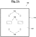
Fig. 2A shows a possible exemplary embodiment of the sensorized device for the detection of analytes within a fluid, according to the present invention; -
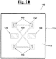
Fig. 2B shows another possible exemplary embodiment of the sensorized device; -
Figs. 3A, 3B, 3C ,3D, 3E and 3F show some possible dispositions of the interdigital transducers and of the reflector electrodes on the outer surface of the substrate. - With reference to the flow-
sheet 300 ofFig. 1 , the method for the detection of analytes within a fluid, according to the present invention, comprises a first step of prearranging asensorized device 100, of which one possible exemplary embodiment is shown inFig. 2A [301]. - In particular, the
sensorized device 100 ofFig. 2A comprises 4SAW sensors 110, each of which comprising in turn asubstrate 115 having an outer surface 115' with at least one piezoelectric portion. With reference even atFigs. 3A, 3B, 3C ,3D, 3E and 3F eachSAW sensor 110 comprises at least one emittinginterdigital transducer 111 and at least onereflector electrode 112 arranged on the piezoelectric portion of the outer surface 115'. In particular, the emittinginterdigital transducer 111 is adapted to emit a surface acoustic wave in response to an input electric signal, whereas thereflector electrode 112 is adapted to reflect the acoustic wave towards the emittinginterdigital transducer 111. - Furthermore, the
sensorized device 100 can comprise at least one auxiliaryinterdigital transducer 120 arranged to emit a surface acoustic wave having frequency ft for introducing turbulence in the fluid. - Sill with reference to the flow-
sheet 300 ofFig. 1 , the method provides then a step of adsorbing a plurality of probe molecules on the outer surface 115' of thesubstrate 115 and/or on the electrodes of the emittinginterdigital transducer 111 and of the reflector electrode 112 [302]. - Then there is a step of sending n input electric signals, having respective frequencies fi , with i = 1, ... , n, to the emitting
interdigital transducer 111 and subsequent transmission of at least one surface acoustic wave [303]. - There is then a step of reflecting by said or each
reflector electrode 112 of said or each surface acoustic wave emitted [304]. - On the basis of the reflected signal and/or transmitted, it is possible to identify, between the n frequencies fi of the input electric signals, at least one resonance frequency fr corresponding to the generation of a surface acoustic wave having power exceeding a predetermined threshold PT [305]. Such identifying can be carried out graphically, identifying, in the spectrum of the reflected signal, the peaks higher than a certain value, i.e. at which the acoustic wave has been actually generated and therefore at which the energy of the reflected signal is low or zero.
- There is then a step of conveying the fluid at the probe molecules, i.e. on the outer surface 115' of the
substrate 115 and/or on the electrodes of the emittinginterdigital transducer 111 and of the reflector electrode 112 [306]. - With reference to
Fig. 2B , in a preferred exemplary embodiment, thedevice 100 comprises at least onemicrofluidic channel 130 arranged to provide the step of conveying by channelling the fluid along a predetermined path on the outer surface 115', in order to contain the fluid in a minimum volume where the analysis is carried out. Themicrofluidic channel 130 may also comprise an analysis chamber 130' at eachSAW sensor 110 for allowing the stationing and/or the movement of the fluid on the electrodes ofsuch SAW sensors 110. - In a preferred exemplary embodiment, the
device 100 comprises at least one auxiliaryinterdigital transducer 120 arranged to emit a surface acoustic wave having frequency ft for introducing turbulence in the fluid. - Then there is a step of removing the fluid by the area wherein it was conveyed [307].
there is then a step of verifying a possible change of value of at least one resonance frequency fr previously identified [308]. - The invention is defined in the appended claims.
Claims (11)
- A method for the detection of analytes within a fluid, said method comprising the steps of:- prearranging a sensorized device (100) comprising at least one SAW sensor (110), said or each SAW sensor (110) comprising:- a substrate (115) having an outer surface (115') comprising at least one piezoelectric portion;- at least one emitting interdigital transducer (111) arranged on said piezoelectric portion of said outer surface (115'), said emitting interdigital transducer (111) arranged to emit a surface acoustic wave in response to an input electric signal;- at least one reflector electrode (112) arranged on said outer surface (115'), said reflector electrode (112) arranged to reflect said surface acoustic wave towards said emitting interdigital transducer (111);- adsorbing a plurality of probe molecules on said outer surface (115') of said substrate (115) and/or on said or each emitting interdigital transducer (111) and/or on said or each reflector electrode (112);- sending n input electric signals, having respective frequencies fi , with i = 1, ... , n, to said emitting interdigital transducer (111) and subsequent transmission by said or each emitting interdigital transducer (111) of at least one surface acoustic wave;- reflecting by said or each reflector electrode (112) of said or each emitted surface acoustic wave;- identifying, between said n frequencies fi of said input electric signals, at least one resonance frequency fr corresponding to a generation of a surface acoustic wave having power exceeding a predetermined threshold PT;- conveying said fluid on said outer surface (115') and/or on said or each emitting interdigital transducer (111) and/or on said or each reflector electrode (112);- removing said fluid by said outer surface (115') and/or from said or each emitting interdigital transducer (111) and/or from said or each reflector electrode (112);- verifying a possible change of value of at least one resonance frequency fr previously identified;said method characterized in that said sensorized device (100) also comprises an auxiliary interdigital transducer (120) arranged on said piezoelectric portion of said outer surface (115'),in that, simultaneously or upstream of said step of conveying said fluid on said outer surface (115'), a step is provided of transmission, by said auxiliary interdigital transducer (120), of a surface acoustic wave having frequency ft for introducing turbulence in said fluid,and in that said or each SAW sensor (110) is a R-SAW sensor adapted to generate Rayleigh surface acoustic waves.
- The method for the detection of analytes within a fluid, according to claim 1, wherein said step of adsorbing a plurality of probe molecules is carried out on said or each emitting interdigital transducer (111) and/or on said or each reflector electrode (112).
- The method for the detection of analytes within a fluid, according to claim 1, wherein said frequencies fi of said n surface acoustic waves emitted by said emitting interdigital transducer (111) are greater than 800MHz, whereas said frequency ft emitted by said auxiliary interdigital transducer (120) is less than 800MHz.
- The method for the detection of analytes within a fluid, according to claim 1, wherein said sensorized device (100) comprises at least two SAW sensors (110) and a control unit and wherein a step is also provided of comparing said surface acoustic waves reflected by said reflector electrodes (112) of said at least two SAW sensors (110) for reducing noise and determine with higher precision said or each resonance frequency fr.
- The method for the detection of analytes within a fluid, according to claim 1, wherein said sensorized device (100) comprises at least one microfluidic channel (130) arranged to convey said fluid along a predetermined path on said outer surface (115'), in order to contain said fluid in a minimum volume where said analysis is carried out.
- The method for the detection of analytes within a fluid, according to claim 1, wherein said piezoelectric portion of said substrate (115) is made of Lithium niobate [LN].
- The method for the detection of analytes within a fluid, according to claim 1, wherein there is a step of defining at least two resonance frequencies fr.
- A sensorized device (100) for the detection of analytes within a fluid, said sensorized device (100) comprising at least one SAW sensor (110), said or each SAW sensor (110) comprising:- a substrate (115) having an outer surface (115') comprising at least one piezoelectric portion;- an emitting interdigital transducer (111) arranged on said outer surface (115'), said emitting interdigital transducer (111) arranged to emit at least a surface acoustic wave in response to n input electric signals having respective frequencies fi , with i = 1, ... , n, between said n frequencies fi being identifiable at least one resonance frequency fr corresponding to a generation of a surface acoustic wave having power exceeding a predetermined threshold PT;- at least one reflector electrode (112) arranged on said outer surface (115'), said reflector electrode (112) arranged to reflect said surface acoustic wave towards said emitting interdigital transducer (111);said sensorized device (100) characterized in that an auxiliary interdigital transducer (120) is also provided arranged on said piezoelectric portion of said outer surface (115') and arranged to emit a surface acoustic wave having frequency ft for introducing turbulence in said fluid,and in that said or each SAW sensor (110) is a R-SAW sensor adapted to generate Rayleigh surface acoustic waves.
- The sensorized device (100), according to claim 8, wherein said frequencies fi of said n surface acoustic waves emitted by said emitting interdigital transducer (111) are greater than 800MHz, whereas said frequency ft emitted by said auxiliary interdigital transducer (120) is less than 800MHz.
- The sensorized device (100), according to claim 8, wherein at least two SAW sensors (110) and a control unit are provided arranged to compare said surface acoustic waves reflected by said reflector electrodes (112) of said at least two SAW sensors (110) for reducing noise.
- The sensorized device (100), according to claim 8, wherein at least one microfluidic channel (130) is provided arranged to convey said fluid along a predetermined path on said outer surface (115'), in order to contain said fluid in a minimum volume where said analysis is carried out.
Applications Claiming Priority (2)
| Application Number | Priority Date | Filing Date | Title |
|---|---|---|---|
| IT102019000000418A IT201900000418A1 (en) | 2019-01-10 | 2019-01-10 | Sensorized device for the analysis of a fluid by means of acoustic waves |
| PCT/IB2020/050151 WO2020144620A1 (en) | 2019-01-10 | 2020-01-09 | Sensorized device for the analysis of a fluid by means of acoustic waves |
Publications (2)
| Publication Number | Publication Date |
|---|---|
| EP3908834A1 EP3908834A1 (en) | 2021-11-17 |
| EP3908834B1 true EP3908834B1 (en) | 2022-10-19 |
Family
ID=66166410
Family Applications (1)
| Application Number | Title | Priority Date | Filing Date |
|---|---|---|---|
| EP20704075.9A Active EP3908834B1 (en) | 2019-01-10 | 2020-01-09 | Sensorized device for the analysis of a fluid by means of acoustic waves |
Country Status (9)
| Country | Link |
|---|---|
| US (1) | US12306136B2 (en) |
| EP (1) | EP3908834B1 (en) |
| JP (1) | JP7478448B2 (en) |
| KR (1) | KR102921741B1 (en) |
| CN (1) | CN113316717B (en) |
| ES (1) | ES2936015T3 (en) |
| IT (1) | IT201900000418A1 (en) |
| PL (1) | PL3908834T3 (en) |
| WO (1) | WO2020144620A1 (en) |
Family Cites Families (37)
| Publication number | Priority date | Publication date | Assignee | Title |
|---|---|---|---|---|
| US5571944A (en) * | 1994-12-20 | 1996-11-05 | Sandia Corporation | Acoustic wave (AW) based moisture sensor for use with corrosive gases |
| JPH11163662A (en) * | 1997-11-27 | 1999-06-18 | Kyocera Corp | Surface acoustic wave filter |
| US6330831B1 (en) * | 1998-10-20 | 2001-12-18 | Panametrics, Inc. | Stream-cleaned differential reflection coefficient sensor |
| DE60027309T2 (en) * | 1999-07-02 | 2006-08-31 | Symyx Technologies, Inc., Santa Clara | POLYMER BRANCHES FOR THE IMMOBILIZATION OF MOLECULES ON SURFACES OR SUBSTRATES WHERE THE POLYMERS HAVE WATER-SOLUBLE OR WATER-DISPERSIBLE SEGMENTS AND PROBES |
| US6293136B1 (en) * | 1999-08-26 | 2001-09-25 | The United States Of America As Represented By The Secretary Of The Army | Multiple mode operated surface acoustic wave sensor for temperature compensation |
| DE10103954B4 (en) * | 2001-01-30 | 2005-10-06 | Advalytix Ag | Method for analyzing macromolecules |
| DE10117772C2 (en) * | 2001-04-09 | 2003-04-03 | Advalytix Ag | Mixing device and mixing method for mixing small amounts of liquid |
| CN1176527C (en) * | 2002-02-07 | 2004-11-17 | 重庆大学 | Passive Wireless Surface Acoustic Wave Multi-Sensor System and Its Frequency Division Identification Method |
| JP2005121498A (en) * | 2003-10-17 | 2005-05-12 | Sony Corp | Surface acoustic wave sensing system |
| US20070166700A1 (en) * | 2004-01-30 | 2007-07-19 | Tan Ooi K | Sensing biological analytes on a ferroelectric transducer |
| US7399280B2 (en) * | 2004-04-21 | 2008-07-15 | Honeywell International Inc. | Passive and wireless in-vivo acoustic wave flow sensor |
| DE602005015913D1 (en) * | 2004-06-11 | 2009-09-24 | Ulvac Inc | Two-frequency measuring method for a surface wave sensor, as well as surface wave sensor and biosensor with means for mixing the analysis fluid |
| JP4504106B2 (en) * | 2004-06-11 | 2010-07-14 | 株式会社アルバック | Measuring method using surface acoustic wave device |
| US7205701B2 (en) * | 2004-09-03 | 2007-04-17 | Honeywell International Inc. | Passive wireless acoustic wave chemical sensor |
| GB0420155D0 (en) * | 2004-09-10 | 2004-10-13 | Univ Cambridge Tech | Liquid mixing/reactor device and method |
| US7289203B2 (en) * | 2004-09-30 | 2007-10-30 | Chromaplex, Inc. | Method and system for spectral analysis of biological materials using stimulated cars |
| US7942568B1 (en) * | 2005-06-17 | 2011-05-17 | Sandia Corporation | Active micromixer using surface acoustic wave streaming |
| JP4900387B2 (en) * | 2006-06-16 | 2012-03-21 | 株式会社村田製作所 | Submerged substance detection sensor |
| US7500379B2 (en) * | 2006-06-26 | 2009-03-10 | Applied Sensor Research & Development Corporation | Acoustic wave array chemical and biological sensor |
| WO2008019693A2 (en) | 2006-08-17 | 2008-02-21 | Atonomics A/S | Bio surface acoustic wave (saw) resonator amplification for detection of a target analyte |
| WO2008019694A2 (en) * | 2006-08-17 | 2008-02-21 | Atonomics A/S | Bio surface acoustic wave (saw) resonator design for detection of a target analyte |
| KR20080039631A (en) * | 2006-11-01 | 2008-05-07 | 주식회사 메디슨 | Probe Characterization Apparatus and Method |
| JPWO2008102577A1 (en) * | 2007-02-19 | 2010-05-27 | 株式会社村田製作所 | Surface acoustic wave sensor device |
| TW200900696A (en) * | 2007-06-25 | 2009-01-01 | Univ Chang Gung | Streptavidin surface-acoustic-wave immunosensor apparatus |
| RU2387051C1 (en) * | 2008-12-01 | 2010-04-20 | Федеральное Государственное Образовательное Учреждение Высшего Профессионального Образования "Южный Федеральный Университет" | Detector of physical value on surface acoustic waves |
| KR101149297B1 (en) * | 2008-12-19 | 2012-05-25 | 삼성전자주식회사 | Dual mode acoustic wave sensor, fabrication method thereof and biosensor system using the same |
| JP5195926B2 (en) * | 2009-01-13 | 2013-05-15 | 株式会社村田製作所 | Elastic wave sensor |
| CN101644618B (en) * | 2009-04-17 | 2011-12-28 | 中国科学院声学研究所 | Surface acoustic wave reflective delay line applied in wireless pressure sensor |
| CN201464095U (en) * | 2009-05-20 | 2010-05-12 | 中国科学院声学研究所 | An Integrated Surface Acoustic Wave Wireless Pressure Sensor |
| CN101644608B (en) * | 2009-05-20 | 2013-05-29 | 中国科学院声学研究所 | Integrated surface acoustic wave wireless temperature sensor |
| JP5281489B2 (en) * | 2009-06-09 | 2013-09-04 | 太陽誘電株式会社 | Surface acoustic wave device |
| JP2013062158A (en) * | 2011-09-14 | 2013-04-04 | Seiko Epson Corp | Light source device and projector |
| CA2853032C (en) * | 2011-12-16 | 2016-11-29 | Halliburton Energy Services, Inc. | Fluid flow control |
| US9726646B1 (en) * | 2013-05-29 | 2017-08-08 | National Technology & Engineering Solutions Of Sandia, Llc | Resonant surface acoustic wave chemical detector |
| US10031140B1 (en) * | 2015-01-26 | 2018-07-24 | University Of South Florida | Orthogonal SAW transducers on substrate for simultaneous biofouling removal and biosensing |
| EP3112869A1 (en) * | 2015-06-30 | 2017-01-04 | IMEC vzw | Sensor device |
| CN108593765A (en) * | 2018-04-04 | 2018-09-28 | 深圳大学 | A kind of biosensor and its detection method based on surface acoustic wave pattern |
-
2019
- 2019-01-10 IT IT102019000000418A patent/IT201900000418A1/en unknown
-
2020
- 2020-01-09 JP JP2021540315A patent/JP7478448B2/en active Active
- 2020-01-09 WO PCT/IB2020/050151 patent/WO2020144620A1/en not_active Ceased
- 2020-01-09 ES ES20704075T patent/ES2936015T3/en active Active
- 2020-01-09 EP EP20704075.9A patent/EP3908834B1/en active Active
- 2020-01-09 US US17/422,131 patent/US12306136B2/en active Active
- 2020-01-09 CN CN202080008716.XA patent/CN113316717B/en active Active
- 2020-01-09 PL PL20704075.9T patent/PL3908834T3/en unknown
- 2020-01-09 KR KR1020217024621A patent/KR102921741B1/en active Active
Also Published As
| Publication number | Publication date |
|---|---|
| US12306136B2 (en) | 2025-05-20 |
| IT201900000418A1 (en) | 2020-07-10 |
| CN113316717B (en) | 2025-05-02 |
| ES2936015T3 (en) | 2023-03-13 |
| WO2020144620A1 (en) | 2020-07-16 |
| JP7478448B2 (en) | 2024-05-07 |
| CN113316717A (en) | 2021-08-27 |
| KR20210110869A (en) | 2021-09-09 |
| EP3908834A1 (en) | 2021-11-17 |
| PL3908834T3 (en) | 2023-03-13 |
| JP2022517994A (en) | 2022-03-11 |
| KR102921741B1 (en) | 2026-02-03 |
| US20220128511A1 (en) | 2022-04-28 |
Similar Documents
| Publication | Publication Date | Title |
|---|---|---|
| KR102810749B1 (en) | Genomic sensing for sample characterization | |
| JP4933956B2 (en) | A surface acoustic wave sensor and a biomolecule measuring apparatus including the surface acoustic wave sensor. | |
| Zhang et al. | Sensitive detection of carcinoembryonic antigen in exhaled breath condensate using surface acoustic wave immunosensor | |
| US20180334697A1 (en) | Method for isothermal dna detection using a modified crispr/cas system and the apparatus for detection by surface acoustic waves for gene editing | |
| WO2008019693A3 (en) | Bio surface acoustic wave (saw) resonator amplification for detection of a target analyte | |
| CN103412056B (en) | A Method of Acoustic Emission Wave Mode Separation in Plate-Like Structures Based on Dual Sensors | |
| KR20200044795A (en) | Multi-surface seismic sensor with delay line coding | |
| US12306136B2 (en) | Sensorized device for the analysis of a fluid by means of acoustic waves | |
| CN115791512B (en) | Non-destructive evaluation method and apparatus for density assessment of selected area laser melting additive manufacturing components | |
| WO2009145385A1 (en) | Resonance characteristic measurement apparatus of cantilever structure and measurement method thereof | |
| Smith et al. | The new era of SAW devices | |
| HK40058493A (en) | Sensorized device for the analysis of a fluid by means of acoustic waves | |
| US20110236877A1 (en) | Biosensor and method using the same to perform a biotest | |
| Sisman et al. | A low-cost biomarker-based SAW-biosensor design for early detection of prostate cancer | |
| JP4826194B2 (en) | Surface acoustic wave device and method of using the same | |
| US20210341424A1 (en) | Device for determining information of a substance in a matter | |
| JP2006121234A (en) | Surface acoustic wave element identification device and acoustic wave element identification device | |
| WO2020053561A1 (en) | Characterisation method and apparatus | |
| US20240315136A1 (en) | Piezoelectric acoustic biosensor and uses therefore | |
| Tan et al. | PMUT-Based Devices and Machine Learning-Assisted Noninvasive-Bubble Recognition for Small Pipes | |
| Suchithra et al. | Terahertz Sensing Using Metasurface Antenna | |
| US20060154300A1 (en) | Biomolecule bonding detection apparatus using wireless antenna and method thereof | |
| Kilifarev et al. | Model for determining of optimal ultrasonic sensors measurement zone | |
| US11275084B2 (en) | Successive sampling device and associated method | |
| CN106770376B (en) | Biosensor based on radio frequency technology |
Legal Events
| Date | Code | Title | Description |
|---|---|---|---|
| STAA | Information on the status of an ep patent application or granted ep patent |
Free format text: STATUS: UNKNOWN |
|
| STAA | Information on the status of an ep patent application or granted ep patent |
Free format text: STATUS: THE INTERNATIONAL PUBLICATION HAS BEEN MADE |
|
| PUAI | Public reference made under article 153(3) epc to a published international application that has entered the european phase |
Free format text: ORIGINAL CODE: 0009012 |
|
| STAA | Information on the status of an ep patent application or granted ep patent |
Free format text: STATUS: REQUEST FOR EXAMINATION WAS MADE |
|
| 17P | Request for examination filed |
Effective date: 20210730 |
|
| AK | Designated contracting states |
Kind code of ref document: A1 Designated state(s): AL AT BE BG CH CY CZ DE DK EE ES FI FR GB GR HR HU IE IS IT LI LT LU LV MC MK MT NL NO PL PT RO RS SE SI SK SM TR |
|
| DAV | Request for validation of the european patent (deleted) | ||
| DAX | Request for extension of the european patent (deleted) | ||
| GRAP | Despatch of communication of intention to grant a patent |
Free format text: ORIGINAL CODE: EPIDOSNIGR1 |
|
| STAA | Information on the status of an ep patent application or granted ep patent |
Free format text: STATUS: GRANT OF PATENT IS INTENDED |
|
| INTG | Intention to grant announced |
Effective date: 20220513 |
|
| GRAS | Grant fee paid |
Free format text: ORIGINAL CODE: EPIDOSNIGR3 |
|
| GRAA | (expected) grant |
Free format text: ORIGINAL CODE: 0009210 |
|
| STAA | Information on the status of an ep patent application or granted ep patent |
Free format text: STATUS: THE PATENT HAS BEEN GRANTED |
|
| AK | Designated contracting states |
Kind code of ref document: B1 Designated state(s): AL AT BE BG CH CY CZ DE DK EE ES FI FR GB GR HR HU IE IS IT LI LT LU LV MC MK MT NL NO PL PT RO RS SE SI SK SM TR |
|
| REG | Reference to a national code |
Ref country code: GB Ref legal event code: FG4D |
|
| REG | Reference to a national code |
Ref country code: CH Ref legal event code: EP |
|
| REG | Reference to a national code |
Ref country code: IE Ref legal event code: FG4D |
|
| REG | Reference to a national code |
Ref country code: DE Ref legal event code: R096 Ref document number: 602020005752 Country of ref document: DE |
|
| REG | Reference to a national code |
Ref country code: AT Ref legal event code: REF Ref document number: 1525856 Country of ref document: AT Kind code of ref document: T Effective date: 20221115 |
|
| REG | Reference to a national code |
Ref country code: NL Ref legal event code: FP |
|
| REG | Reference to a national code |
Ref country code: LT Ref legal event code: MG9D |
|
| REG | Reference to a national code |
Ref country code: ES Ref legal event code: FG2A Ref document number: 2936015 Country of ref document: ES Kind code of ref document: T3 Effective date: 20230313 |
|
| REG | Reference to a national code |
Ref country code: AT Ref legal event code: MK05 Ref document number: 1525856 Country of ref document: AT Kind code of ref document: T Effective date: 20221019 |
|
| PG25 | Lapsed in a contracting state [announced via postgrant information from national office to epo] |
Ref country code: SE Free format text: LAPSE BECAUSE OF FAILURE TO SUBMIT A TRANSLATION OF THE DESCRIPTION OR TO PAY THE FEE WITHIN THE PRESCRIBED TIME-LIMIT Effective date: 20221019 Ref country code: PT Free format text: LAPSE BECAUSE OF FAILURE TO SUBMIT A TRANSLATION OF THE DESCRIPTION OR TO PAY THE FEE WITHIN THE PRESCRIBED TIME-LIMIT Effective date: 20230220 Ref country code: NO Free format text: LAPSE BECAUSE OF FAILURE TO SUBMIT A TRANSLATION OF THE DESCRIPTION OR TO PAY THE FEE WITHIN THE PRESCRIBED TIME-LIMIT Effective date: 20230119 Ref country code: LT Free format text: LAPSE BECAUSE OF FAILURE TO SUBMIT A TRANSLATION OF THE DESCRIPTION OR TO PAY THE FEE WITHIN THE PRESCRIBED TIME-LIMIT Effective date: 20221019 Ref country code: FI Free format text: LAPSE BECAUSE OF FAILURE TO SUBMIT A TRANSLATION OF THE DESCRIPTION OR TO PAY THE FEE WITHIN THE PRESCRIBED TIME-LIMIT Effective date: 20221019 Ref country code: AT Free format text: LAPSE BECAUSE OF FAILURE TO SUBMIT A TRANSLATION OF THE DESCRIPTION OR TO PAY THE FEE WITHIN THE PRESCRIBED TIME-LIMIT Effective date: 20221019 |
|
| PG25 | Lapsed in a contracting state [announced via postgrant information from national office to epo] |
Ref country code: RS Free format text: LAPSE BECAUSE OF FAILURE TO SUBMIT A TRANSLATION OF THE DESCRIPTION OR TO PAY THE FEE WITHIN THE PRESCRIBED TIME-LIMIT Effective date: 20221019 Ref country code: LV Free format text: LAPSE BECAUSE OF FAILURE TO SUBMIT A TRANSLATION OF THE DESCRIPTION OR TO PAY THE FEE WITHIN THE PRESCRIBED TIME-LIMIT Effective date: 20221019 Ref country code: IS Free format text: LAPSE BECAUSE OF FAILURE TO SUBMIT A TRANSLATION OF THE DESCRIPTION OR TO PAY THE FEE WITHIN THE PRESCRIBED TIME-LIMIT Effective date: 20230219 Ref country code: HR Free format text: LAPSE BECAUSE OF FAILURE TO SUBMIT A TRANSLATION OF THE DESCRIPTION OR TO PAY THE FEE WITHIN THE PRESCRIBED TIME-LIMIT Effective date: 20221019 Ref country code: GR Free format text: LAPSE BECAUSE OF FAILURE TO SUBMIT A TRANSLATION OF THE DESCRIPTION OR TO PAY THE FEE WITHIN THE PRESCRIBED TIME-LIMIT Effective date: 20230120 |
|
| REG | Reference to a national code |
Ref country code: DE Ref legal event code: R097 Ref document number: 602020005752 Country of ref document: DE |
|
| PG25 | Lapsed in a contracting state [announced via postgrant information from national office to epo] |
Ref country code: SM Free format text: LAPSE BECAUSE OF FAILURE TO SUBMIT A TRANSLATION OF THE DESCRIPTION OR TO PAY THE FEE WITHIN THE PRESCRIBED TIME-LIMIT Effective date: 20221019 Ref country code: RO Free format text: LAPSE BECAUSE OF FAILURE TO SUBMIT A TRANSLATION OF THE DESCRIPTION OR TO PAY THE FEE WITHIN THE PRESCRIBED TIME-LIMIT Effective date: 20221019 Ref country code: EE Free format text: LAPSE BECAUSE OF FAILURE TO SUBMIT A TRANSLATION OF THE DESCRIPTION OR TO PAY THE FEE WITHIN THE PRESCRIBED TIME-LIMIT Effective date: 20221019 Ref country code: DK Free format text: LAPSE BECAUSE OF FAILURE TO SUBMIT A TRANSLATION OF THE DESCRIPTION OR TO PAY THE FEE WITHIN THE PRESCRIBED TIME-LIMIT Effective date: 20221019 Ref country code: CZ Free format text: LAPSE BECAUSE OF FAILURE TO SUBMIT A TRANSLATION OF THE DESCRIPTION OR TO PAY THE FEE WITHIN THE PRESCRIBED TIME-LIMIT Effective date: 20221019 |
|
| PLBE | No opposition filed within time limit |
Free format text: ORIGINAL CODE: 0009261 |
|
| STAA | Information on the status of an ep patent application or granted ep patent |
Free format text: STATUS: NO OPPOSITION FILED WITHIN TIME LIMIT |
|
| PG25 | Lapsed in a contracting state [announced via postgrant information from national office to epo] |
Ref country code: SK Free format text: LAPSE BECAUSE OF FAILURE TO SUBMIT A TRANSLATION OF THE DESCRIPTION OR TO PAY THE FEE WITHIN THE PRESCRIBED TIME-LIMIT Effective date: 20221019 Ref country code: AL Free format text: LAPSE BECAUSE OF FAILURE TO SUBMIT A TRANSLATION OF THE DESCRIPTION OR TO PAY THE FEE WITHIN THE PRESCRIBED TIME-LIMIT Effective date: 20221019 |
|
| REG | Reference to a national code |
Ref country code: CH Ref legal event code: PL |
|
| 26N | No opposition filed |
Effective date: 20230720 |
|
| PG25 | Lapsed in a contracting state [announced via postgrant information from national office to epo] |
Ref country code: LU Free format text: LAPSE BECAUSE OF NON-PAYMENT OF DUE FEES Effective date: 20230109 |
|
| REG | Reference to a national code |
Ref country code: BE Ref legal event code: MM Effective date: 20230131 |
|
| PG25 | Lapsed in a contracting state [announced via postgrant information from national office to epo] |
Ref country code: LI Free format text: LAPSE BECAUSE OF NON-PAYMENT OF DUE FEES Effective date: 20230131 Ref country code: CH Free format text: LAPSE BECAUSE OF NON-PAYMENT OF DUE FEES Effective date: 20230131 |
|
| PG25 | Lapsed in a contracting state [announced via postgrant information from national office to epo] |
Ref country code: SI Free format text: LAPSE BECAUSE OF FAILURE TO SUBMIT A TRANSLATION OF THE DESCRIPTION OR TO PAY THE FEE WITHIN THE PRESCRIBED TIME-LIMIT Effective date: 20221019 Ref country code: BE Free format text: LAPSE BECAUSE OF NON-PAYMENT OF DUE FEES Effective date: 20230131 |
|
| PG25 | Lapsed in a contracting state [announced via postgrant information from national office to epo] |
Ref country code: IE Free format text: LAPSE BECAUSE OF NON-PAYMENT OF DUE FEES Effective date: 20230109 |
|
| PG25 | Lapsed in a contracting state [announced via postgrant information from national office to epo] |
Ref country code: MC Free format text: LAPSE BECAUSE OF FAILURE TO SUBMIT A TRANSLATION OF THE DESCRIPTION OR TO PAY THE FEE WITHIN THE PRESCRIBED TIME-LIMIT Effective date: 20221019 |
|
| PG25 | Lapsed in a contracting state [announced via postgrant information from national office to epo] |
Ref country code: MC Free format text: LAPSE BECAUSE OF FAILURE TO SUBMIT A TRANSLATION OF THE DESCRIPTION OR TO PAY THE FEE WITHIN THE PRESCRIBED TIME-LIMIT Effective date: 20221019 |
|
| PG25 | Lapsed in a contracting state [announced via postgrant information from national office to epo] |
Ref country code: BG Free format text: LAPSE BECAUSE OF FAILURE TO SUBMIT A TRANSLATION OF THE DESCRIPTION OR TO PAY THE FEE WITHIN THE PRESCRIBED TIME-LIMIT Effective date: 20221019 |
|
| PG25 | Lapsed in a contracting state [announced via postgrant information from national office to epo] |
Ref country code: BG Free format text: LAPSE BECAUSE OF FAILURE TO SUBMIT A TRANSLATION OF THE DESCRIPTION OR TO PAY THE FEE WITHIN THE PRESCRIBED TIME-LIMIT Effective date: 20221019 |
|
| PG25 | Lapsed in a contracting state [announced via postgrant information from national office to epo] |
Ref country code: CY Free format text: LAPSE BECAUSE OF FAILURE TO SUBMIT A TRANSLATION OF THE DESCRIPTION OR TO PAY THE FEE WITHIN THE PRESCRIBED TIME-LIMIT; INVALID AB INITIO Effective date: 20200109 |
|
| PG25 | Lapsed in a contracting state [announced via postgrant information from national office to epo] |
Ref country code: HU Free format text: LAPSE BECAUSE OF FAILURE TO SUBMIT A TRANSLATION OF THE DESCRIPTION OR TO PAY THE FEE WITHIN THE PRESCRIBED TIME-LIMIT; INVALID AB INITIO Effective date: 20200109 |
|
| PG25 | Lapsed in a contracting state [announced via postgrant information from national office to epo] |
Ref country code: TR Free format text: LAPSE BECAUSE OF FAILURE TO SUBMIT A TRANSLATION OF THE DESCRIPTION OR TO PAY THE FEE WITHIN THE PRESCRIBED TIME-LIMIT Effective date: 20221019 |
|
| PGFP | Annual fee paid to national office [announced via postgrant information from national office to epo] |
Ref country code: GB Payment date: 20251224 Year of fee payment: 7 |
|
| PGFP | Annual fee paid to national office [announced via postgrant information from national office to epo] |
Ref country code: FR Payment date: 20251224 Year of fee payment: 7 |
|
| PGFP | Annual fee paid to national office [announced via postgrant information from national office to epo] |
Ref country code: PL Payment date: 20251229 Year of fee payment: 7 |
|
| PGFP | Annual fee paid to national office [announced via postgrant information from national office to epo] |
Ref country code: NL Payment date: 20260128 Year of fee payment: 7 |
|
| PGFP | Annual fee paid to national office [announced via postgrant information from national office to epo] |
Ref country code: ES Payment date: 20260202 Year of fee payment: 7 |
|
| PGFP | Annual fee paid to national office [announced via postgrant information from national office to epo] |
Ref country code: DE Payment date: 20260128 Year of fee payment: 7 |
|
| PGFP | Annual fee paid to national office [announced via postgrant information from national office to epo] |
Ref country code: IT Payment date: 20251229 Year of fee payment: 7 |