EP3908407B1 - Vorrichtung zur abgabe von flüssigkeiten oder mischungen - Google Patents
Vorrichtung zur abgabe von flüssigkeiten oder mischungen Download PDFInfo
- Publication number
- EP3908407B1 EP3908407B1 EP19850794.9A EP19850794A EP3908407B1 EP 3908407 B1 EP3908407 B1 EP 3908407B1 EP 19850794 A EP19850794 A EP 19850794A EP 3908407 B1 EP3908407 B1 EP 3908407B1
- Authority
- EP
- European Patent Office
- Prior art keywords
- fluid
- dispensing
- suited
- deformable membrane
- collapsible chamber
- Prior art date
- Legal status (The legal status is an assumption and is not a legal conclusion. Google has not performed a legal analysis and makes no representation as to the accuracy of the status listed.)
- Active
Links
Images


Classifications
-
- B—PERFORMING OPERATIONS; TRANSPORTING
- B05—SPRAYING OR ATOMISING IN GENERAL; APPLYING FLUENT MATERIALS TO SURFACES, IN GENERAL
- B05B—SPRAYING APPARATUS; ATOMISING APPARATUS; NOZZLES
- B05B11/00—Single-unit hand-held apparatus in which flow of contents is produced by the muscular force of the operator at the moment of use
- B05B11/01—Single-unit hand-held apparatus in which flow of contents is produced by the muscular force of the operator at the moment of use characterised by the means producing the flow
- B05B11/10—Pump arrangements for transferring the contents from the container to a pump chamber by a sucking effect and forcing the contents out through the dispensing nozzle
- B05B11/1028—Pumps having a pumping chamber with a deformable wall
- B05B11/1032—Pumps having a pumping chamber with a deformable wall actuated without substantial movement of the nozzle in the direction of the pressure stroke
-
- B—PERFORMING OPERATIONS; TRANSPORTING
- B05—SPRAYING OR ATOMISING IN GENERAL; APPLYING FLUENT MATERIALS TO SURFACES, IN GENERAL
- B05B—SPRAYING APPARATUS; ATOMISING APPARATUS; NOZZLES
- B05B11/00—Single-unit hand-held apparatus in which flow of contents is produced by the muscular force of the operator at the moment of use
- B05B11/01—Single-unit hand-held apparatus in which flow of contents is produced by the muscular force of the operator at the moment of use characterised by the means producing the flow
- B05B11/10—Pump arrangements for transferring the contents from the container to a pump chamber by a sucking effect and forcing the contents out through the dispensing nozzle
- B05B11/1042—Components or details
- B05B11/1059—Means for locking a pump or its actuation means in a fixed position
- B05B11/106—Means for locking a pump or its actuation means in a fixed position in a retracted position, e.g. in an end-of-dispensing-stroke position
-
- B—PERFORMING OPERATIONS; TRANSPORTING
- B05—SPRAYING OR ATOMISING IN GENERAL; APPLYING FLUENT MATERIALS TO SURFACES, IN GENERAL
- B05B—SPRAYING APPARATUS; ATOMISING APPARATUS; NOZZLES
- B05B11/00—Single-unit hand-held apparatus in which flow of contents is produced by the muscular force of the operator at the moment of use
- B05B11/0005—Components or details
- B05B11/0062—Outlet valves actuated by the pressure of the fluid to be sprayed
- B05B11/007—Outlet valves actuated by the pressure of the fluid to be sprayed being opened by deformation of a sealing element made of resiliently deformable material, e.g. flaps, skirts, duck-bill valves
-
- B—PERFORMING OPERATIONS; TRANSPORTING
- B05—SPRAYING OR ATOMISING IN GENERAL; APPLYING FLUENT MATERIALS TO SURFACES, IN GENERAL
- B05B—SPRAYING APPARATUS; ATOMISING APPARATUS; NOZZLES
- B05B11/00—Single-unit hand-held apparatus in which flow of contents is produced by the muscular force of the operator at the moment of use
- B05B11/0005—Components or details
- B05B11/0089—Dispensing tubes
- B05B11/0091—Dispensing tubes movable, e.g. articulated on the sprayer
- B05B11/0094—Dispensing tubes movable, e.g. articulated on the sprayer movement of the dispensing tube controlling a valve
-
- B—PERFORMING OPERATIONS; TRANSPORTING
- B05—SPRAYING OR ATOMISING IN GENERAL; APPLYING FLUENT MATERIALS TO SURFACES, IN GENERAL
- B05B—SPRAYING APPARATUS; ATOMISING APPARATUS; NOZZLES
- B05B11/00—Single-unit hand-held apparatus in which flow of contents is produced by the muscular force of the operator at the moment of use
- B05B11/01—Single-unit hand-held apparatus in which flow of contents is produced by the muscular force of the operator at the moment of use characterised by the means producing the flow
- B05B11/10—Pump arrangements for transferring the contents from the container to a pump chamber by a sucking effect and forcing the contents out through the dispensing nozzle
- B05B11/1042—Components or details
- B05B11/1043—Sealing or attachment arrangements between pump and container
- B05B11/1046—Sealing or attachment arrangements between pump and container the pump chamber being arranged substantially coaxially to the neck of the container
- B05B11/1047—Sealing or attachment arrangements between pump and container the pump chamber being arranged substantially coaxially to the neck of the container the pump being preassembled as an independent unit before being mounted on the container
-
- B—PERFORMING OPERATIONS; TRANSPORTING
- B05—SPRAYING OR ATOMISING IN GENERAL; APPLYING FLUENT MATERIALS TO SURFACES, IN GENERAL
- B05B—SPRAYING APPARATUS; ATOMISING APPARATUS; NOZZLES
- B05B11/00—Single-unit hand-held apparatus in which flow of contents is produced by the muscular force of the operator at the moment of use
- B05B11/01—Single-unit hand-held apparatus in which flow of contents is produced by the muscular force of the operator at the moment of use characterised by the means producing the flow
- B05B11/10—Pump arrangements for transferring the contents from the container to a pump chamber by a sucking effect and forcing the contents out through the dispensing nozzle
- B05B11/1042—Components or details
- B05B11/1066—Pump inlet valves
- B05B11/1067—Pump inlet valves actuated by pressure
Definitions
- the present invention concerns the technical field of the systems for dispensing fluids or mixtures.
- the present invention concerns a device for dispensing a fluid which is suited to be applied to a container holding the fluid itself, particularly suited to dispense food substances, perfumes or detergents in general.
- dispensing devices with collapsible chamber is known in the sector of systems for dispensing liquid or creamy products, such as food products, soaps, creams, detergents or perfumes, wherein said devices are applied to the container holding said products.
- These devices are substantially constituted by a supporting structure provided with means for coupling the device with the neck of the container and by a dispensing unit suited to dispense the fluid held in the container.
- the dispensing unit is preferably constituted by a collapsible chamber suited to draw and contain an amount of the fluid coming from the container and to dispense a portion of said amount towards a dispensing nozzle.
- the fluid is drawn into the collapsible chamber and dispensed through a manual operation performed by the user, who first directly exerts a compressing action with one or more fingers on a deformable membrane that delimits said chamber and then releases it.
- the fluid contained inside the collapsible chamber is dispensed towards the external environment by means of the dispensing nozzle.
- the deformable membrane automatically returns to its non-compressed configuration, drawing into the collapsible chamber an amount of fluid which will remain contained therein, ready for the successive dispensing operation.
- the deformable membrane is typically constituted by an elastically yielding and therefore deformable hemispherical element, which is suited to be deformed so that, starting from its initial hemispherical shape, it finally reaches a squeezed configuration, and then returns to its initial hemispherical shape after being released.
- a first drawback of these dispensing devices is related to the transport and handling steps that follow its assembly on the container holding the product.
- the deformable membrane can be subjected to inadvertent impacts or deformation, causing the liquid to be undesirably dispensed.
- the deformable membrane can be undesirably subjected to a deforming action and consequently cause the liquid to be undesirably dispensed.
- storage operations may require that several assemblies comprising the container and the corresponding device are stacked on top of one another, and their weight may deform the deformable membrane in a permanent manner, making it lose part of its elasticity characteristics and irreparably compromising its operation.
- the present invention is based on the general consideration according to which it is desirable to provide a device for dispensing a fluid, wherein said device is suited to be connected to a container holding said fluid and can be operated by acting on a deformable membrane provided with locking means suited to maintain the deformable membrane in a fixed squeezed position.
- the subject of the same is a device for dispensing a fluid
- said device comprising a supporting structure provided with means for coupling the device itself with a container holding said fluid and a collapsible chamber associated with said supporting structure and suited to draw, contain and dispense an amount of said fluid
- said device comprising a suction duct suited to place said collapsible chamber in communication with said container and a dispensing duct suited to place said collapsible chamber in communication with the outside, said collapsible chamber being at least partially delimited by a deformable membrane suited to be squeezed to dispense at least one portion of said amount from said collapsible chamber
- the device comprises locking means suited to maintain said deformable membrane in a locked squeezed position and release means suited to release said deformable membrane from said locked squeezed position
- the release means comprise cam release means configured in such a way that moving the deformable membrane causes the locking means to be released.
- the locking means comprise also obstructing means suited to obstruct the suction duct when the deformable membrane is in the locked squeezed position.
- the locking means comprise snap-fitting locking means.
- the supporting structure comprises a first portion and a second portion connected to the first portion, said second portion being movable with respect to said first portion and said deformable membrane being associated with said second portion, said second portion being preferably suited to be rotated with respect to said first portion.
- the release means are configured in such a way that moving the second portion with respect to the first portion causes said locking means to be released, preferably causes the second portion to be rotated with respect to the first portion.
- the dispensing duct, the second portion and the deformable membrane are made in a single body and they are preferably made of PE.
- the device comprises suction valve means suited to regulate the flow of fluid from the suction duct into the collapsible chamber.
- the device comprises dispensing valve means suited to regulate the dispensing of the fluid from the collapsible chamber towards the dispensing duct.
- the dispensing valve means comprise a flexible edge suited to assume a closed position intended to prevent the passage of fluid from the collapsible chamber towards the dispensing duct and suited to assume an open position intended to allow the passage of fluid from the collapsible chamber towards the dispensing duct.
- the deformable membrane comprises an elastically yielding sphere portion associated with the supporting structure.
- the coupling means allow the device to be removably coupled with the container.
- the subject of the same is a system for dispensing a fluid, comprising a container for said fluid and a device for dispensing said fluid made as described above.
- the fluid can also be dispensed in the form of spray, on condition that the device is provided with suitable means for the generation of said spray such as, for example, a diffuser element.
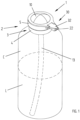
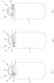
- FIG. 1 An example of embodiment of a device for dispensing fluids, which is the subject of the present invention, and is applied to a container C containing a fluid L to be dispensed, is illustrated in Figure 1 , where it is indicated as a whole by the numeral 1.
- the device 1 comprises a supporting structure 2 provided with coupling means 3 for coupling the device itself with the container C.
- Said coupling means 3 are preferably constituted by a threaded portion 3a, visible in Figure 2 , suited to be engaged in a corresponding threaded portion Cf present on the neck of the container C.
- said coupling means can be of a different type, for example they can be snap-fitting coupling means.
- the coupling means are preferably made in such a way as to allow the device to be removably coupled with the container.
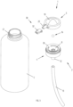
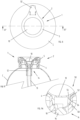
- the supporting element 2 is preferably made in two parts, a lower part 4 (first part) and an upper part 5 (second part), suited to be associated with each other with a snap-in action and better illustrated in Figure 4 .
- the upper part 5 is associated with the lower part 4 in such a way that the upper part 5 can be moved with respect to the lower part 4, preferably in such a way that the upper part 5 can rotate by a predetermined angle with respect to the lower part 4.
- the upper part 5 can rotate by an angle of 90° with respect to the lower part 4.
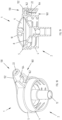
- a collapsible chamber 6 is defined between the lower part 4 and the upper part 5 of the supporting element 2, and is suited to draw, contain and dispense an amount of fluid L, as is better described below.
- the collapsible chamber 6 is delimited at its bottom by a surface 8, preferably in the shape of a truncated cone, of the lower part 4 and is delimited at its top by a deformable membrane 10.
- the deformable membrane 10 is preferably made in a single body with the upper part 5.
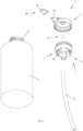
- the device 1 comprises a suction duct 12 suited to place the collapsible chamber 6 in communication with the container C.
- the suction duct 12 is partially defined in the lower part 4 of the supporting element 2 and furthermore it preferably comprises a small tube 13 in a predetermined length which is suited to substantially reach the bottom of the container C.
- suction valve means 14 arranged between the collapsible chamber 6 and the suction duct 12 and suited to regulate the flow of the fluid L in the collapsible chamber 6.
- the suction valve means 14 preferably comprise a sphere 16 accommodated in a housing portion 18 obtained in the lower part 4 of the supporting structure 2. Inside said housing portion 18 the sphere 16 can be arranged in different positions in order to allow the suction duct 12 to be selectively opened and closed during the operation of the device 1, as will be better explained in the rest of the description.
- the device 1 comprises a dispensing duct 22 suited to place the collapsible chamber 6 in communication with the outside and to dispense the fluid L towards the outside of the device 1 and thus towards the outside of the container C.
- the dispensing duct 22, the upper part 5 and the deformable membrane 10 are made in a single body, more preferably they are made of PE.
- the dispensing duct 22 is associated with an anti-dispensing safety system 30 comprising a nozzle 32 which is preferably hinged to the upper part 5 of the supporting element 2.
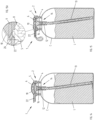
- the nozzle 32 can assume a first anti-dispensing position, in which it is folded in such a way as to fold and throttle the dispensing duct 22, as shown for example in Figure 5 , and a second position, in which the nozzle 32 is rotated and the dispensing duct 22 is free and can dispense the fluid, as shown in Figures 6 and 7 .
- Figures 18 and 19 show a variant embodiment of the anti-dispensing safety system 130 which comprises holding means 160 suited to maintain the nozzle 132 in the folded position.
- the holding means 160 preferably comprise mechanical interference means comprising a projecting element 162 made on the upper part 5 of the supporting structure 2 and a slit 164 made in the lower part of the nozzle 132.
- the projecting element 162 is suited to be snap-fitted in the slit 164.
- the holding means 160 maintain the nozzle 132 in that position safely, as shown in Figure 19 .
- the user must release the nozzle 132 by rotating it and arranging it in the horizontal position.
- dispensing valve means 24 arranged between the collapsible chamber 6 and the dispensing duct 22 and suited to regulate the outflow of the fluid L from the inside of the collapsible chamber 6 towards the dispensing duct 22 and thus towards the outside.
- the dispensing valve means 24 preferably comprise a flexible edge 26 belonging to the lower part 4 of the supporting element 2 and suited to assume a closed position intended to prevent the passage of fluid L from the inside of the collapsible chamber 6 towards the outside and an open position intended to allow the passage of fluid L from the inside of the collapsible chamber 6 towards the dispensing duct 22 and thus towards the outside of the container C (as shown, for example, in the detail of Figure 15A and better described below).
- the deformable membrane 10 preferably hemispherical in shape, is elastically yielding and therefore deformable.
- the deformable membrane 10 is suited to be squeezed to dispense a quantity of fluid L from the collapsible chamber 6.
- the device comprises locking means 50 suited to maintain the deformable membrane 10 in a fixed squeezed position.
- a fixed squeezed position of the deformable membrane 10 according to the invention is shown in Figures 5, 6 and in Figures 8, 9 and 9A .
- the fixed squeezed position of the deformable membrane 10 is a position in which the membrane 10 is arranged before the device 1 is used.
- the deformable membrane 10 is arranged in that position by the manufacturer/assembler immediately after the container C has been filled with the fluid L or is arranged in that position by the manufacturer/assembler of the device 1 which is successively assembled on the container C holding the fluid F.
- the device 1 furthermore comprises release means 80 suited to release the deformable membrane 10 from the fixed squeezed position.
- the device 1 can be used normally, as described below.
- the locking means 50 preferably comprise a snap-fitting locking system.
- the locking means 50 preferably comprise a projecting annular edge 52, preferably defined on the external surface of a stem 54 extending from the deformable membrane 10 towards the collapsible chamber 6, and a corresponding recessed annular edge 56, preferably made in a cylindrical seat 58 of the lower part 4 of the supporting element 2.
- the projecting annular edge 52 snap fits in the recessed annular edge 56, compressing with a given force the deformable membrane 10 which is thus maintained in the fixed squeezed position.
- the snap-fitting locking system can be made in a different way, for example with different geometrical shapes of said edges, or inverting the position of the projecting edge with respect to the recessed edge.
- the cylindrical seat 58 of the lower part 4 on which the recessed annular edge 56 is defined is created at the level of the terminal part of the suction duct 12 towards the collapsible chamber 6.
- the stem 54 of the deformable membrane 10 is fitted in the cylindrical seat 58 in such a way as to obstruct the suction duct 12.
- the locking means 50 in addition to guaranteeing that the deformable membrane 10 is maintained in the desired squeezed position, guarantee the hydraulic sealing of the suction duct 12, avoiding any leakage of fluid L from the container C.
- said hydraulic sealing characteristic may be absent.
- the release means 80 according to the embodiment shown and described herein comprise a cam release system.
- the locking means 80 preferably comprise two inclined surfaces 84a, 84b obtained at the end of the stem 54 and corresponding inclined surfaces 86a, 86b created in the cylindrical seat 58 of the lower part 4 of the supporting element 2.
- the inclined surfaces 84a, 84b of the stem 54 and the corresponding inclined surfaces 86a, 86b of the cylindrical seat 58 are in contact with one another.
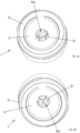
- the upper part 5 of the supporting element 2 is arranged with a predetermined orientation with respect to the lower part 4, as shown for example in Figures 5, 6 and 8 .
- the upper part 5 of the supporting element 2 is rotated with respect to the lower part 4, as can be understood by comparing the Figures from 8 to 13.
- the upper part 5 of the supporting element 2 is rotated by 90° with respect to the lower part 4.
- the extent of the rotation can be different.
- the inclined surfaces 84a, 84b of the stem 54 and the corresponding inclined surfaces 86a, 86b of the cylindrical seat 58 interact (cam effect) and the stem 54 is pushed in a direction away from the cylindrical seat 58 together with the deformable membrane 10 or, in other words, the deformable membrane 10 is freed/released from the fixed squeezed position by extracting the projecting annular edge 52 of the stem 54 from the recessed annular edge 56 of the cylindrical seat 58.
- Said release of the deformable membrane 10 takes place in the first rotation step of the upper part 5 with respect to the lower part 4, for example after a rotation of approximately 10°.
- the deformable membrane 10 thanks to its elasticity, automatically returns to its totally expanded configuration, ready for normal use, as shown in Figure 13 .
- the locking means 50 make it possible to arrange the deformable membrane 10 in a fixed squeezed position before the device 1 is used.
- the deformable membrane 10 is arranged in the fixed squeezed position by the manufacturer/assembler immediately after the container C has been filled with the fluid L, or by the manufacturer/assembler of the device 1.
- the liquid is prevented from being undesirably dispensed, especially when the device is transported or handled by the user before it is actually used.
- the fixed squeezed position 50 of the deformable membrane 10 reduces the overall dimensions of the device 1, making it easier to store the device 1 or the assembly comprising also the container C. Furthermore, there is no need to worry about the storage position of the assembly, which can also be positioned upside down.
- the fixed squeezed position 50 of the deformable membrane 10 makes it possible to store several assemblies made up the container C and the respective device 1, stacked on one another, with no need to worry about the weight deforming the deformable membrane 10 in a permanent manner.
- Figure 14 the device 1 is in a rest condition, ready to be used, with the deformable membrane 10 completely expanded.
- Figure 15 shows the first step of operation of the device 1, in which the deformable membrane 10 is squeezed.
- the sphere 16 obstructs the suction duct 12, so that the fluid L is compressed and conveyed from the inside of the collapsible chamber 6 only towards the dispensing duct 22.
- the stop position is preferably defined by the contact of the lower surface 92 of the stem 54 with a reference surface 90 of the lower part 4 of the supporting element 2, as shown in the detail of Figure 16A. It is obvious that in variant embodiments the stop position can be obtained with different means.
- a predetermined quantity of fluid L will be dispensed from the collapsible chamber 6 towards the outside through the dispensing duct 22.
- the quantity of fluid L dispensed can be smaller if the deformable membrane 10 is released before reaching its stop position.
- the step of release of the deformable membrane 10 starts once the fluid L dispensing step has been completed and coincides with the step of suction of the fluid L from the container C, which is intended to refill the collapsible chamber 6 with the quantity of fluid L which will be used for the successive dispensing cycle.
- Figure 17 shows the release step, in which the flexible edge 26, among the other things, returns to the position in which it closes the dispensing duct 22.
- the deformable membrane 10 is automatically decompressed thanks to its intrinsic elastic yielding characteristics and the fluid L is drawn from the inside of the container C along the suction duct 12 into the collapsible chamber 6.
- the volume of the collapsible chamber 6 is completely restored and the sphere 16 is arranged again in such a way as to obstruct the suction duct 12, while the device 1 returns to its initial condition, that is, the condition shown in Figure 14 , with the collapsible chamber 6 filled with an amount of fluid L suited to be used for the successive dispensing operation.
- the present invention allows the set objectives to be achieved. More specifically, it makes it possible to provide a device for dispensing a fluid which can be transported and handled by the user in a safer manner compared to the systems of the known type.
- the description of the present invention refers to the activation of the deformable membrane carried out directly by the user.
- the deformable membrane can be squeezed using auxiliary means, for example using a lever or equivalent means.
Landscapes
- Containers And Packaging Bodies Having A Special Means To Remove Contents (AREA)
- Nozzles (AREA)
Claims (12)
- Vorrichtung (1) zum Abgeben eines Fluids (L), wobei die Vorrichtung (1) eine Tragestruktur (2, 4, 5), die mit Mitteln (3) zum Koppeln derselben mit einem Behälter (C), der das Fluid (L) aufnimmt, bereitgestellt ist, und eine zusammendrückbare Kammer (6), die der Tragestruktur (2, 4, 5) zugeordnet ist, umfasst, wobei die zusammendrückbare Kammer (6) geeignet ist, eine Menge des Fluids (L) anzusaugen, zu enthalten und abzugeben, wobei die Vorrichtung (1) eine Ansaugleitung (12), die geeignet ist, der zusammendrückbaren Kammer (6) zu ermöglichen, mit dem Behälter (C) zu kommunizieren, und eine Abgabeleitung (22) umfasst, die geeignet ist, der zusammendrückbaren Kammer (6) zu ermöglichen, mit der Außenumgebung zu kommunizieren, wobei die zusammendrückbare Kammer (6) zumindest teilweise durch eine verformbare Membran (10) begrenzt ist, die geeignet ist, zusammengedrückt zu werden, um zumindest einen Teil der Menge aus der zusammendrückbaren Kammer (6) abzugeben, wobei die Vorrichtung Verriegelungsmittel (50, 52, 56), die geeignet sind, die verformbare Membran (10) in einer festen zusammengedrückten Position zu halten, und Freigabemittel (80, 84a, 84b, 86a, 86b) umfasst, die geeignet sind, die verformbare Membran (10) aus der festen zusammengedrückten Position zu lösen, und dadurch gekennzeichnet, dass die Freigabemittel (80, 84a, 84b, 86a, 86b) Nockenfreigabemittel (80, 84a, 84b, 86a, 86b) umfassen, die derart geformt sind, dass ein Bewegen der verformbaren Membran (10) bewirkt, dass die Verriegelungsmittel (50, 52, 56) gelöst werden.
- Vorrichtung (1) nach Anspruch 1, dadurch gekennzeichnet, dass die Verriegelungsmittel (50, 52, 56) ferner Verschlussmittel umfassen, die dazu ausgelegt sind, die Ansaugleitung (12) zu verschließen, wenn die verformbare Membran (10) in der festen zusammengedrückten Position gehalten wird.
- Vorrichtung (1) nach Anspruch 1 oder 2, dadurch gekennzeichnet, dass die Verriegelungsmittel (50, 52, 56) Einrastverriegelungsmittel (50, 52, 56) umfassen.
- Vorrichtung (1) nach einem der vorangegangenen Ansprüche, dadurch gekennzeichnet, dass die Tragestruktur (2, 4, 5) einen ersten Teil (4) und einen mit dem ersten Teil (4) verbundenen zweiten Teil (5) umfasst, wobei der zweite Teil (5) in Bezug auf den ersten Teil (4) bewegbar ist und die verformbare Membran (10) dem zweiten Teil (5) zugeordnet ist, wobei der zweite Teil (5) vorzugsweise geeignet ist, in Bezug auf den ersten Teil (4) gedreht zu werden.
- Vorrichtung (1) nach Anspruch 4, dadurch gekennzeichnet, dass die Freigabemittel (80, 84a, 84b, 86a, 86b) derart geformt sind, dass ein Bewegen des zweiten Teils (5) in Bezug auf den ersten Teil (4), vorzugsweise das Drehen des zweiten Teils (5) in Bezug auf den ersten Teil (4), das Lösen der Verriegelungselemente (50, 52, 56) bewirkt.
- Vorrichtung (1) nach Anspruch 4 oder 5, dadurch gekennzeichnet, dass die Abgabeleitung (22), der zweite Teil (5) und die verformbare Membran (10) einstückig ausgebildet und vorzugsweise aus PE gefertigt sind.
- Vorrichtung (1) nach einem der vorangegangenen Ansprüche, dadurch gekennzeichnet, dass sie Ansaugventilmittel (14, 16) umfasst, die geeignet sind, die Strömung des Fluids (L) aus der Ansaugleitung (12) in die zusammendrückbare Kammer (6) zu regulieren.
- Vorrichtung (1) nach einem der vorangegangenen Ansprüche, dadurch gekennzeichnet, dass sie Abgabeventilmittel (24) umfasst, die geeignet sind, die Strömung des abgegebenen Fluids (L) aus der zusammendrückbaren Kammer (6) zur Abgabeleitung (22) zu regulieren.
- Vorrichtung (1) nach Anspruch 8, dadurch gekennzeichnet, dass die Abgabeventilmittel (24) eine flexible Kante (26) aufweisen, die geeignet ist, eine geschlossene Position einzunehmen, um das Durchtreten von Fluid (L) aus der zusammendrückbaren Kammer (6) in die Abgabeleitung (22) zu verhindern, und eine offene Position einzunehmen, die das Durchtreten von Fluid (L) aus der zusammendrückbaren Kammer (6) in die Abgabeleitung (22) zu ermöglichen.
- Vorrichtung (1) nach einem der vorangegangenen Ansprüche, dadurch gekennzeichnet, dass die verformbare Membran (10) einen elastisch nachgebenden Kugelabschnitt umfasst, der der Tragestruktur (2, 4, 5) zugeordnet ist.
- Vorrichtung (1) nach einem der vorangegangenen Ansprüche, dadurch gekennzeichnet, dass die Kopplungsmittel (3) ein lösbares Koppeln der Vorrichtung (1) mit dem Behälter (C) ermöglichen.
- System zum Abgeben eines Fluids (L), umfassend einen Behälter (C) für das Fluid (L) und eine Vorrichtung (1) zum Abgeben des Fluids (L), dadurch gekennzeichnet, dass die Abgabevorrichtung (1) gemäß einem der vorangegangenen Ansprüche gefertigt ist.
Applications Claiming Priority (2)
| Application Number | Priority Date | Filing Date | Title |
|---|---|---|---|
| IT102019000000199A IT201900000199A1 (it) | 2019-01-08 | 2019-01-08 | Dispositivo per l'erogazione di fluidi o miscele |
| PCT/IB2019/061431 WO2020144532A1 (en) | 2019-01-08 | 2019-12-30 | Device for dispensing fluids or mixtures |
Publications (2)
| Publication Number | Publication Date |
|---|---|
| EP3908407A1 EP3908407A1 (de) | 2021-11-17 |
| EP3908407B1 true EP3908407B1 (de) | 2023-10-25 |
Family
ID=66166376
Family Applications (1)
| Application Number | Title | Priority Date | Filing Date |
|---|---|---|---|
| EP19850794.9A Active EP3908407B1 (de) | 2019-01-08 | 2019-12-30 | Vorrichtung zur abgabe von flüssigkeiten oder mischungen |
Country Status (5)
| Country | Link |
|---|---|
| US (1) | US11648576B2 (de) |
| EP (1) | EP3908407B1 (de) |
| CN (1) | CN113474087B (de) |
| IT (1) | IT201900000199A1 (de) |
| WO (1) | WO2020144532A1 (de) |
Families Citing this family (1)
| Publication number | Priority date | Publication date | Assignee | Title |
|---|---|---|---|---|
| IT202100020864A1 (it) * | 2021-08-03 | 2023-02-03 | Taplast Srl | Pompa monopolimerica, azionata a cupola |
Citations (2)
| Publication number | Priority date | Publication date | Assignee | Title |
|---|---|---|---|---|
| US2884164A (en) * | 1957-03-08 | 1959-04-28 | Arnold Copeland Co Inc | Fluid dispenser |
| WO2002004129A1 (en) * | 2000-07-06 | 2002-01-17 | Advanex Inc. | Valve unit and container |
Family Cites Families (11)
| Publication number | Priority date | Publication date | Assignee | Title |
|---|---|---|---|---|
| US4369899A (en) | 1980-11-18 | 1983-01-25 | Realex Corporation | Down-locking pump |
| FR2711554B1 (fr) * | 1993-10-22 | 1995-12-22 | Oreal | Ensemble de distribution à reprise d'air commandée. |
| US5501375A (en) * | 1994-05-12 | 1996-03-26 | Cenova Innovations & Produktions Ab | Dispenser valve for dispensing a pressurized liquid |
| US5549223A (en) * | 1994-08-03 | 1996-08-27 | Toyo Seikan Kaisha, Ltd. | Pump with back suction phase |
| US5544789A (en) * | 1995-01-05 | 1996-08-13 | Calmar Inc. | Bellows pump dispenser |
| US5871126A (en) * | 1996-01-22 | 1999-02-16 | Chesebrough-Pond's Usa Co., Division Of Conopco, Inc. | Pump dispenser |
| NL1028730C2 (nl) * | 2004-09-16 | 2006-03-20 | Keltub B V | Samenstel van balg en tegendeel. |
| ES2222851B1 (es) | 2004-10-20 | 2005-10-01 | Saint-Gobain Calmar, S.A. | Bomba con mecanismo de cierre. |
| ITRM20070538A1 (it) * | 2007-10-12 | 2009-04-13 | Emsar Spa | Erogatore di prodotti fluidi. |
| GB0901907D0 (en) * | 2009-02-05 | 2009-03-11 | Leafgreen Ltd | Manual pump type fluid dispenser |
| ITRM20080263A1 (it) * | 2008-05-16 | 2009-11-17 | Emsar Spa | Erogatore di prodotti fluidi. |
-
2019
- 2019-01-08 IT IT102019000000199A patent/IT201900000199A1/it unknown
- 2019-12-30 CN CN201980092912.7A patent/CN113474087B/zh active Active
- 2019-12-30 EP EP19850794.9A patent/EP3908407B1/de active Active
- 2019-12-30 US US17/421,426 patent/US11648576B2/en active Active
- 2019-12-30 WO PCT/IB2019/061431 patent/WO2020144532A1/en not_active Ceased
Patent Citations (2)
| Publication number | Priority date | Publication date | Assignee | Title |
|---|---|---|---|---|
| US2884164A (en) * | 1957-03-08 | 1959-04-28 | Arnold Copeland Co Inc | Fluid dispenser |
| WO2002004129A1 (en) * | 2000-07-06 | 2002-01-17 | Advanex Inc. | Valve unit and container |
Also Published As
| Publication number | Publication date |
|---|---|
| WO2020144532A1 (en) | 2020-07-16 |
| EP3908407A1 (de) | 2021-11-17 |
| CN113474087B (zh) | 2023-07-14 |
| CN113474087A (zh) | 2021-10-01 |
| US11648576B2 (en) | 2023-05-16 |
| IT201900000199A1 (it) | 2020-07-08 |
| US20220118469A1 (en) | 2022-04-21 |
Similar Documents
| Publication | Publication Date | Title |
|---|---|---|
| EP2599558B1 (de) | Luftloses Pumpensystem | |
| US4260079A (en) | Manually operated liquid dispensers | |
| US6338442B1 (en) | Dispenser for dispensing a product | |
| US8875951B2 (en) | Aerosol cap and system for dispensing a fluid from a canister | |
| US6715649B2 (en) | Bellows pump for delivery of liquids | |
| US4872595A (en) | Mechanically pressurized aerosol dispenser | |
| AU2001266022A1 (en) | Bellows pump for delivery of liquids | |
| US5813573A (en) | Dispenser for the simultaneous delivery of at least two paste-like products | |
| US11179739B2 (en) | Liquid dispenser | |
| US6910603B2 (en) | Leak preventing closure in a dispenser pump | |
| US10661292B2 (en) | Device for dispensing fluids or mixtures | |
| EP3908407B1 (de) | Vorrichtung zur abgabe von flüssigkeiten oder mischungen | |
| US10807113B2 (en) | Device for dispensing fluids or mixtures | |
| US20230331446A1 (en) | Table top dispensers with anti-refill and anti-tampering mechanisms | |
| EP1638751B1 (de) | Verbesserungen in bezug auf austragvorrichtung | |
| EP3030123B1 (de) | Spender | |
| US4938393A (en) | Bimodal storage and dispensing package for fluent material | |
| JP2000281156A (ja) | エアゾール容器 | |
| WO2003078074A1 (en) | Pump unit and container | |
| RU2850410C1 (ru) | Триггерное дозирующее устройство со средством для предотвращения потери продукта | |
| EP1991362B1 (de) | Pumpe zur manuellen abgabe eines in einem behälter enthaltenen fluiden stoffes | |
| JP2025057848A (ja) | 吐出器 | |
| WO1993024238A1 (en) | Fluid delivery systems | |
| HK40070061A (en) | Dispenser for viscous products | |
| US20110030551A1 (en) | Pump device and methods of making the same |
Legal Events
| Date | Code | Title | Description |
|---|---|---|---|
| STAA | Information on the status of an ep patent application or granted ep patent |
Free format text: STATUS: UNKNOWN |
|
| STAA | Information on the status of an ep patent application or granted ep patent |
Free format text: STATUS: THE INTERNATIONAL PUBLICATION HAS BEEN MADE |
|
| PUAI | Public reference made under article 153(3) epc to a published international application that has entered the european phase |
Free format text: ORIGINAL CODE: 0009012 |
|
| STAA | Information on the status of an ep patent application or granted ep patent |
Free format text: STATUS: REQUEST FOR EXAMINATION WAS MADE |
|
| 17P | Request for examination filed |
Effective date: 20210804 |
|
| AK | Designated contracting states |
Kind code of ref document: A1 Designated state(s): AL AT BE BG CH CY CZ DE DK EE ES FI FR GB GR HR HU IE IS IT LI LT LU LV MC MK MT NL NO PL PT RO RS SE SI SK SM TR |
|
| DAV | Request for validation of the european patent (deleted) | ||
| DAX | Request for extension of the european patent (deleted) | ||
| STAA | Information on the status of an ep patent application or granted ep patent |
Free format text: STATUS: EXAMINATION IS IN PROGRESS |
|
| 17Q | First examination report despatched |
Effective date: 20220804 |
|
| REG | Reference to a national code |
Ref country code: DE Ref legal event code: R079 Free format text: PREVIOUS MAIN CLASS: B05B0011000000 Ipc: B05B0011100000 Ref country code: DE Ref legal event code: R079 Ref document number: 602019040272 Country of ref document: DE Free format text: PREVIOUS MAIN CLASS: B05B0011000000 Ipc: B05B0011100000 |
|
| GRAP | Despatch of communication of intention to grant a patent |
Free format text: ORIGINAL CODE: EPIDOSNIGR1 |
|
| STAA | Information on the status of an ep patent application or granted ep patent |
Free format text: STATUS: GRANT OF PATENT IS INTENDED |
|
| RIC1 | Information provided on ipc code assigned before grant |
Ipc: B05B 11/00 20060101ALN20230421BHEP Ipc: B05B 11/10 20230101AFI20230421BHEP |
|
| INTG | Intention to grant announced |
Effective date: 20230510 |
|
| GRAS | Grant fee paid |
Free format text: ORIGINAL CODE: EPIDOSNIGR3 |
|
| GRAA | (expected) grant |
Free format text: ORIGINAL CODE: 0009210 |
|
| STAA | Information on the status of an ep patent application or granted ep patent |
Free format text: STATUS: THE PATENT HAS BEEN GRANTED |
|
| AK | Designated contracting states |
Kind code of ref document: B1 Designated state(s): AL AT BE BG CH CY CZ DE DK EE ES FI FR GB GR HR HU IE IS IT LI LT LU LV MC MK MT NL NO PL PT RO RS SE SI SK SM TR |
|
| P01 | Opt-out of the competence of the unified patent court (upc) registered |
Effective date: 20230914 |
|
| REG | Reference to a national code |
Ref country code: GB Ref legal event code: FG4D |
|
| REG | Reference to a national code |
Ref country code: CH Ref legal event code: EP |
|
| REG | Reference to a national code |
Ref country code: DE Ref legal event code: R096 Ref document number: 602019040272 Country of ref document: DE |
|
| REG | Reference to a national code |
Ref country code: IE Ref legal event code: FG4D |
|
| REG | Reference to a national code |
Ref country code: LT Ref legal event code: MG9D |
|
| REG | Reference to a national code |
Ref country code: NL Ref legal event code: MP Effective date: 20231025 |
|
| REG | Reference to a national code |
Ref country code: AT Ref legal event code: MK05 Ref document number: 1624154 Country of ref document: AT Kind code of ref document: T Effective date: 20231025 |
|
| PG25 | Lapsed in a contracting state [announced via postgrant information from national office to epo] |
Ref country code: NL Free format text: LAPSE BECAUSE OF FAILURE TO SUBMIT A TRANSLATION OF THE DESCRIPTION OR TO PAY THE FEE WITHIN THE PRESCRIBED TIME-LIMIT Effective date: 20231025 |
|
| PG25 | Lapsed in a contracting state [announced via postgrant information from national office to epo] |
Ref country code: GR Free format text: LAPSE BECAUSE OF FAILURE TO SUBMIT A TRANSLATION OF THE DESCRIPTION OR TO PAY THE FEE WITHIN THE PRESCRIBED TIME-LIMIT Effective date: 20240126 |
|
| PG25 | Lapsed in a contracting state [announced via postgrant information from national office to epo] |
Ref country code: IS Free format text: LAPSE BECAUSE OF FAILURE TO SUBMIT A TRANSLATION OF THE DESCRIPTION OR TO PAY THE FEE WITHIN THE PRESCRIBED TIME-LIMIT Effective date: 20240225 |
|
| PG25 | Lapsed in a contracting state [announced via postgrant information from national office to epo] |
Ref country code: LT Free format text: LAPSE BECAUSE OF FAILURE TO SUBMIT A TRANSLATION OF THE DESCRIPTION OR TO PAY THE FEE WITHIN THE PRESCRIBED TIME-LIMIT Effective date: 20231025 |
|
| PG25 | Lapsed in a contracting state [announced via postgrant information from national office to epo] |
Ref country code: AT Free format text: LAPSE BECAUSE OF FAILURE TO SUBMIT A TRANSLATION OF THE DESCRIPTION OR TO PAY THE FEE WITHIN THE PRESCRIBED TIME-LIMIT Effective date: 20231025 |
|
| PG25 | Lapsed in a contracting state [announced via postgrant information from national office to epo] |
Ref country code: ES Free format text: LAPSE BECAUSE OF FAILURE TO SUBMIT A TRANSLATION OF THE DESCRIPTION OR TO PAY THE FEE WITHIN THE PRESCRIBED TIME-LIMIT Effective date: 20231025 |
|
| PG25 | Lapsed in a contracting state [announced via postgrant information from national office to epo] |
Ref country code: LT Free format text: LAPSE BECAUSE OF FAILURE TO SUBMIT A TRANSLATION OF THE DESCRIPTION OR TO PAY THE FEE WITHIN THE PRESCRIBED TIME-LIMIT Effective date: 20231025 Ref country code: IS Free format text: LAPSE BECAUSE OF FAILURE TO SUBMIT A TRANSLATION OF THE DESCRIPTION OR TO PAY THE FEE WITHIN THE PRESCRIBED TIME-LIMIT Effective date: 20240225 Ref country code: GR Free format text: LAPSE BECAUSE OF FAILURE TO SUBMIT A TRANSLATION OF THE DESCRIPTION OR TO PAY THE FEE WITHIN THE PRESCRIBED TIME-LIMIT Effective date: 20240126 Ref country code: ES Free format text: LAPSE BECAUSE OF FAILURE TO SUBMIT A TRANSLATION OF THE DESCRIPTION OR TO PAY THE FEE WITHIN THE PRESCRIBED TIME-LIMIT Effective date: 20231025 Ref country code: BG Free format text: LAPSE BECAUSE OF FAILURE TO SUBMIT A TRANSLATION OF THE DESCRIPTION OR TO PAY THE FEE WITHIN THE PRESCRIBED TIME-LIMIT Effective date: 20240125 Ref country code: AT Free format text: LAPSE BECAUSE OF FAILURE TO SUBMIT A TRANSLATION OF THE DESCRIPTION OR TO PAY THE FEE WITHIN THE PRESCRIBED TIME-LIMIT Effective date: 20231025 Ref country code: PT Free format text: LAPSE BECAUSE OF FAILURE TO SUBMIT A TRANSLATION OF THE DESCRIPTION OR TO PAY THE FEE WITHIN THE PRESCRIBED TIME-LIMIT Effective date: 20240226 |
|
| PG25 | Lapsed in a contracting state [announced via postgrant information from national office to epo] |
Ref country code: SE Free format text: LAPSE BECAUSE OF FAILURE TO SUBMIT A TRANSLATION OF THE DESCRIPTION OR TO PAY THE FEE WITHIN THE PRESCRIBED TIME-LIMIT Effective date: 20231025 Ref country code: RS Free format text: LAPSE BECAUSE OF FAILURE TO SUBMIT A TRANSLATION OF THE DESCRIPTION OR TO PAY THE FEE WITHIN THE PRESCRIBED TIME-LIMIT Effective date: 20231025 Ref country code: PL Free format text: LAPSE BECAUSE OF FAILURE TO SUBMIT A TRANSLATION OF THE DESCRIPTION OR TO PAY THE FEE WITHIN THE PRESCRIBED TIME-LIMIT Effective date: 20231025 Ref country code: NO Free format text: LAPSE BECAUSE OF FAILURE TO SUBMIT A TRANSLATION OF THE DESCRIPTION OR TO PAY THE FEE WITHIN THE PRESCRIBED TIME-LIMIT Effective date: 20240125 Ref country code: LV Free format text: LAPSE BECAUSE OF FAILURE TO SUBMIT A TRANSLATION OF THE DESCRIPTION OR TO PAY THE FEE WITHIN THE PRESCRIBED TIME-LIMIT Effective date: 20231025 Ref country code: HR Free format text: LAPSE BECAUSE OF FAILURE TO SUBMIT A TRANSLATION OF THE DESCRIPTION OR TO PAY THE FEE WITHIN THE PRESCRIBED TIME-LIMIT Effective date: 20231025 |
|
| PG25 | Lapsed in a contracting state [announced via postgrant information from national office to epo] |
Ref country code: DK Free format text: LAPSE BECAUSE OF FAILURE TO SUBMIT A TRANSLATION OF THE DESCRIPTION OR TO PAY THE FEE WITHIN THE PRESCRIBED TIME-LIMIT Effective date: 20231025 |
|
| PG25 | Lapsed in a contracting state [announced via postgrant information from national office to epo] |
Ref country code: CZ Free format text: LAPSE BECAUSE OF FAILURE TO SUBMIT A TRANSLATION OF THE DESCRIPTION OR TO PAY THE FEE WITHIN THE PRESCRIBED TIME-LIMIT Effective date: 20231025 |
|
| REG | Reference to a national code |
Ref country code: DE Ref legal event code: R097 Ref document number: 602019040272 Country of ref document: DE |
|
| PG25 | Lapsed in a contracting state [announced via postgrant information from national office to epo] |
Ref country code: SK Free format text: LAPSE BECAUSE OF FAILURE TO SUBMIT A TRANSLATION OF THE DESCRIPTION OR TO PAY THE FEE WITHIN THE PRESCRIBED TIME-LIMIT Effective date: 20231025 |
|
| PG25 | Lapsed in a contracting state [announced via postgrant information from national office to epo] |
Ref country code: SM Free format text: LAPSE BECAUSE OF FAILURE TO SUBMIT A TRANSLATION OF THE DESCRIPTION OR TO PAY THE FEE WITHIN THE PRESCRIBED TIME-LIMIT Effective date: 20231025 Ref country code: SK Free format text: LAPSE BECAUSE OF FAILURE TO SUBMIT A TRANSLATION OF THE DESCRIPTION OR TO PAY THE FEE WITHIN THE PRESCRIBED TIME-LIMIT Effective date: 20231025 Ref country code: RO Free format text: LAPSE BECAUSE OF FAILURE TO SUBMIT A TRANSLATION OF THE DESCRIPTION OR TO PAY THE FEE WITHIN THE PRESCRIBED TIME-LIMIT Effective date: 20231025 Ref country code: EE Free format text: LAPSE BECAUSE OF FAILURE TO SUBMIT A TRANSLATION OF THE DESCRIPTION OR TO PAY THE FEE WITHIN THE PRESCRIBED TIME-LIMIT Effective date: 20231025 Ref country code: DK Free format text: LAPSE BECAUSE OF FAILURE TO SUBMIT A TRANSLATION OF THE DESCRIPTION OR TO PAY THE FEE WITHIN THE PRESCRIBED TIME-LIMIT Effective date: 20231025 Ref country code: CZ Free format text: LAPSE BECAUSE OF FAILURE TO SUBMIT A TRANSLATION OF THE DESCRIPTION OR TO PAY THE FEE WITHIN THE PRESCRIBED TIME-LIMIT Effective date: 20231025 |
|
| REG | Reference to a national code |
Ref country code: CH Ref legal event code: PL |
|
| PG25 | Lapsed in a contracting state [announced via postgrant information from national office to epo] |
Ref country code: LU Free format text: LAPSE BECAUSE OF NON-PAYMENT OF DUE FEES Effective date: 20231230 |
|
| PG25 | Lapsed in a contracting state [announced via postgrant information from national office to epo] |
Ref country code: MC Free format text: LAPSE BECAUSE OF FAILURE TO SUBMIT A TRANSLATION OF THE DESCRIPTION OR TO PAY THE FEE WITHIN THE PRESCRIBED TIME-LIMIT Effective date: 20231025 |
|
| REG | Reference to a national code |
Ref country code: BE Ref legal event code: MM Effective date: 20231231 |
|
| PG25 | Lapsed in a contracting state [announced via postgrant information from national office to epo] |
Ref country code: MC Free format text: LAPSE BECAUSE OF FAILURE TO SUBMIT A TRANSLATION OF THE DESCRIPTION OR TO PAY THE FEE WITHIN THE PRESCRIBED TIME-LIMIT Effective date: 20231025 Ref country code: LU Free format text: LAPSE BECAUSE OF NON-PAYMENT OF DUE FEES Effective date: 20231230 |
|
| PLBE | No opposition filed within time limit |
Free format text: ORIGINAL CODE: 0009261 |
|
| STAA | Information on the status of an ep patent application or granted ep patent |
Free format text: STATUS: NO OPPOSITION FILED WITHIN TIME LIMIT |
|
| 26N | No opposition filed |
Effective date: 20240726 |
|
| REG | Reference to a national code |
Ref country code: IE Ref legal event code: MM4A |
|
| PG25 | Lapsed in a contracting state [announced via postgrant information from national office to epo] |
Ref country code: IE Free format text: LAPSE BECAUSE OF NON-PAYMENT OF DUE FEES Effective date: 20231230 |
|
| PG25 | Lapsed in a contracting state [announced via postgrant information from national office to epo] |
Ref country code: BE Free format text: LAPSE BECAUSE OF NON-PAYMENT OF DUE FEES Effective date: 20231231 |
|
| PG25 | Lapsed in a contracting state [announced via postgrant information from national office to epo] |
Ref country code: CH Free format text: LAPSE BECAUSE OF NON-PAYMENT OF DUE FEES Effective date: 20231231 |
|
| PG25 | Lapsed in a contracting state [announced via postgrant information from national office to epo] |
Ref country code: SI Free format text: LAPSE BECAUSE OF FAILURE TO SUBMIT A TRANSLATION OF THE DESCRIPTION OR TO PAY THE FEE WITHIN THE PRESCRIBED TIME-LIMIT Effective date: 20231025 |
|
| PG25 | Lapsed in a contracting state [announced via postgrant information from national office to epo] |
Ref country code: SI Free format text: LAPSE BECAUSE OF FAILURE TO SUBMIT A TRANSLATION OF THE DESCRIPTION OR TO PAY THE FEE WITHIN THE PRESCRIBED TIME-LIMIT Effective date: 20231025 Ref country code: IE Free format text: LAPSE BECAUSE OF NON-PAYMENT OF DUE FEES Effective date: 20231230 Ref country code: CH Free format text: LAPSE BECAUSE OF NON-PAYMENT OF DUE FEES Effective date: 20231231 Ref country code: BE Free format text: LAPSE BECAUSE OF NON-PAYMENT OF DUE FEES Effective date: 20231231 |
|
| PGFP | Annual fee paid to national office [announced via postgrant information from national office to epo] |
Ref country code: DE Payment date: 20241227 Year of fee payment: 6 |
|
| PG25 | Lapsed in a contracting state [announced via postgrant information from national office to epo] |
Ref country code: FI Free format text: LAPSE BECAUSE OF FAILURE TO SUBMIT A TRANSLATION OF THE DESCRIPTION OR TO PAY THE FEE WITHIN THE PRESCRIBED TIME-LIMIT Effective date: 20231025 |
|
| PG25 | Lapsed in a contracting state [announced via postgrant information from national office to epo] |
Ref country code: CY Free format text: LAPSE BECAUSE OF FAILURE TO SUBMIT A TRANSLATION OF THE DESCRIPTION OR TO PAY THE FEE WITHIN THE PRESCRIBED TIME-LIMIT; INVALID AB INITIO Effective date: 20191230 |
|
| PG25 | Lapsed in a contracting state [announced via postgrant information from national office to epo] |
Ref country code: HU Free format text: LAPSE BECAUSE OF FAILURE TO SUBMIT A TRANSLATION OF THE DESCRIPTION OR TO PAY THE FEE WITHIN THE PRESCRIBED TIME-LIMIT; INVALID AB INITIO Effective date: 20191230 |
|
| PG25 | Lapsed in a contracting state [announced via postgrant information from national office to epo] |
Ref country code: TR Free format text: LAPSE BECAUSE OF FAILURE TO SUBMIT A TRANSLATION OF THE DESCRIPTION OR TO PAY THE FEE WITHIN THE PRESCRIBED TIME-LIMIT Effective date: 20231025 |
|
| PGFP | Annual fee paid to national office [announced via postgrant information from national office to epo] |
Ref country code: GB Payment date: 20251229 Year of fee payment: 7 |
|
| PGFP | Annual fee paid to national office [announced via postgrant information from national office to epo] |
Ref country code: IT Payment date: 20251219 Year of fee payment: 7 |
|
| PGFP | Annual fee paid to national office [announced via postgrant information from national office to epo] |
Ref country code: FR Payment date: 20251226 Year of fee payment: 7 |