EP3908014A1 - Verfahren zur wartung einer datenübertragungsverbindung, verfahren zur auslösung der wartung und vorrichtung - Google Patents
Verfahren zur wartung einer datenübertragungsverbindung, verfahren zur auslösung der wartung und vorrichtung Download PDFInfo
- Publication number
- EP3908014A1 EP3908014A1 EP20735980.3A EP20735980A EP3908014A1 EP 3908014 A1 EP3908014 A1 EP 3908014A1 EP 20735980 A EP20735980 A EP 20735980A EP 3908014 A1 EP3908014 A1 EP 3908014A1
- Authority
- EP
- European Patent Office
- Prior art keywords
- pathloss
- transmission link
- transmission
- sidelink
- maintenance
- Prior art date
- Legal status (The legal status is an assumption and is not a legal conclusion. Google has not performed a legal analysis and makes no representation as to the accuracy of the status listed.)
- Withdrawn
Links
Images


Classifications
-
- H—ELECTRICITY
- H04—ELECTRIC COMMUNICATION TECHNIQUE
- H04W—WIRELESS COMMUNICATION NETWORKS
- H04W4/00—Services specially adapted for wireless communication networks; Facilities therefor
- H04W4/30—Services specially adapted for particular environments, situations or purposes
- H04W4/40—Services specially adapted for particular environments, situations or purposes for vehicles, e.g. vehicle-to-pedestrians [V2P]
- H04W4/44—Services specially adapted for particular environments, situations or purposes for vehicles, e.g. vehicle-to-pedestrians [V2P] for communication between vehicles and infrastructures, e.g. vehicle-to-cloud [V2C] or vehicle-to-home [V2H]
-
- H—ELECTRICITY
- H04—ELECTRIC COMMUNICATION TECHNIQUE
- H04B—TRANSMISSION
- H04B1/00—Details of transmission systems, not covered by a single one of groups H04B3/00 - H04B13/00; Details of transmission systems not characterised by the medium used for transmission
- H04B1/005—Details of transmission systems, not covered by a single one of groups H04B3/00 - H04B13/00; Details of transmission systems not characterised by the medium used for transmission adapting radio receivers, transmitters andtransceivers for operation on two or more bands, i.e. frequency ranges
-
- H—ELECTRICITY
- H04—ELECTRIC COMMUNICATION TECHNIQUE
- H04L—TRANSMISSION OF DIGITAL INFORMATION, e.g. TELEGRAPHIC COMMUNICATION
- H04L41/00—Arrangements for maintenance, administration or management of data switching networks, e.g. of packet switching networks
- H04L41/06—Management of faults, events, alarms or notifications
-
- H—ELECTRICITY
- H04—ELECTRIC COMMUNICATION TECHNIQUE
- H04L—TRANSMISSION OF DIGITAL INFORMATION, e.g. TELEGRAPHIC COMMUNICATION
- H04L41/00—Arrangements for maintenance, administration or management of data switching networks, e.g. of packet switching networks
- H04L41/06—Management of faults, events, alarms or notifications
- H04L41/0654—Management of faults, events, alarms or notifications using network fault recovery
-
- H—ELECTRICITY
- H04—ELECTRIC COMMUNICATION TECHNIQUE
- H04W—WIRELESS COMMUNICATION NETWORKS
- H04W4/00—Services specially adapted for wireless communication networks; Facilities therefor
- H04W4/30—Services specially adapted for particular environments, situations or purposes
- H04W4/40—Services specially adapted for particular environments, situations or purposes for vehicles, e.g. vehicle-to-pedestrians [V2P]
-
- H—ELECTRICITY
- H04—ELECTRIC COMMUNICATION TECHNIQUE
- H04W—WIRELESS COMMUNICATION NETWORKS
- H04W4/00—Services specially adapted for wireless communication networks; Facilities therefor
- H04W4/30—Services specially adapted for particular environments, situations or purposes
- H04W4/40—Services specially adapted for particular environments, situations or purposes for vehicles, e.g. vehicle-to-pedestrians [V2P]
- H04W4/46—Services specially adapted for particular environments, situations or purposes for vehicles, e.g. vehicle-to-pedestrians [V2P] for vehicle-to-vehicle communication [V2V]
-
- H—ELECTRICITY
- H04—ELECTRIC COMMUNICATION TECHNIQUE
- H04W—WIRELESS COMMUNICATION NETWORKS
- H04W76/00—Connection management
- H04W76/10—Connection setup
- H04W76/14—Direct-mode setup
-
- H—ELECTRICITY
- H04—ELECTRIC COMMUNICATION TECHNIQUE
- H04L—TRANSMISSION OF DIGITAL INFORMATION, e.g. TELEGRAPHIC COMMUNICATION
- H04L43/00—Arrangements for monitoring or testing data switching networks
- H04L43/08—Monitoring or testing based on specific metrics, e.g. QoS, energy consumption or environmental parameters
- H04L43/0823—Errors, e.g. transmission errors
-
- H—ELECTRICITY
- H04—ELECTRIC COMMUNICATION TECHNIQUE
- H04L—TRANSMISSION OF DIGITAL INFORMATION, e.g. TELEGRAPHIC COMMUNICATION
- H04L43/00—Arrangements for monitoring or testing data switching networks
- H04L43/16—Threshold monitoring
-
- H—ELECTRICITY
- H04—ELECTRIC COMMUNICATION TECHNIQUE
- H04W—WIRELESS COMMUNICATION NETWORKS
- H04W52/00—Power management, e.g. Transmission Power Control [TPC] or power classes
- H04W52/04—Transmission power control [TPC]
- H04W52/18—TPC being performed according to specific parameters
- H04W52/24—TPC being performed according to specific parameters using SIR [Signal to Interference Ratio] or other wireless path parameters
- H04W52/242—TPC being performed according to specific parameters using SIR [Signal to Interference Ratio] or other wireless path parameters taking into account path loss
-
- H—ELECTRICITY
- H04—ELECTRIC COMMUNICATION TECHNIQUE
- H04W—WIRELESS COMMUNICATION NETWORKS
- H04W52/00—Power management, e.g. Transmission Power Control [TPC] or power classes
- H04W52/04—Transmission power control [TPC]
- H04W52/38—TPC being performed in particular situations
- H04W52/383—TPC being performed in particular situations power control in peer-to-peer links
-
- H—ELECTRICITY
- H04—ELECTRIC COMMUNICATION TECHNIQUE
- H04W—WIRELESS COMMUNICATION NETWORKS
- H04W76/00—Connection management
- H04W76/20—Manipulation of established connections
- H04W76/25—Maintenance of established connections
-
- H—ELECTRICITY
- H04—ELECTRIC COMMUNICATION TECHNIQUE
- H04W—WIRELESS COMMUNICATION NETWORKS
- H04W76/00—Connection management
- H04W76/30—Connection release
Definitions
- the present disclosure belongs to the field of wireless communication, and in particular, relates to a method for data transmission link maintenance, and a method for triggering maintenance and apparatus.
- V2X transmission power is a smaller one of maximum transmission power of the UE at a current frequency and required transmission power calculated by the UE based on a pathloss of the cell.
- NR New Radio
- a smaller one of a pathloss of a sidelink for bidirectional transmission and a pathloss, calculated by UE that performs bidirectional transmission, of a cell that serves the UE is generally used as transmission power of the UE.
- the pathloss of the sidelink is generally used as the transmission power of the UE.
- the UE may move during the bidirectional transmission.
- the pathloss of the sidelink may be greater than the pathloss of the cell that serves the UE.
- the pathloss of the cell that serves the UE is used as the transmission power of the UE. Consequently, the sidelink cannot be maintained, and the UE may be suddenly disconnected from the other UE. This greatly affects user experience.
- the present disclosure provides a method and apparatus for data transmission link maintenance, and a method and apparatus for triggering maintenance of a V2X transmission link in time when a relationship between a first pathloss and a second pathloss changes, thereby ensuring a desirable transmission effect of the V2X transmission link and improving user experience.
- a method for data transmission link maintenance includes: establishing a sidelink for transmitting V2X service data, and performing communication between a first UE and a second UE over the sidelink; obtaining a first pathloss; obtaining a second pathloss; and maintaining a V2X transmission link in response to a relationship between the first pathloss and the second pathloss meeting a trigger condition.
- the maintaining a V2X transmission link in response to a relationship between the first pathloss and the second pathloss meeting a trigger condition may specifically include: maintaining the V2X transmission link in response to the first pathloss being greater than the second pathloss by a first threshold; or maintaining the V2X transmission link in response to the first pathloss being less than the second pathloss by a second threshold.
- the maintaining a V2X transmission link may specifically include: sending a first notification message to the second UE, such that the second UE maintains the V2X transmission link based on the first notification message; or sending a second notification message to a base station that serves the first UE to maintain the V2X transmission link; or adjusting transmission parameters to maintain the V2X transmission link.
- the sending a second notification message to a base station that serves the first UE to maintain the V2X transmission link may specifically include: sending the second notification message to the base station to request to perform power compensation based on the first pathloss to implement V2X transmission; and in response to receiving a request approval message, performing power compensation based on the first pathloss to implement V2X transmission; or in response to receiving a request rejection message, adjusting the transmission parameters to maintain the V2X transmission link.
- the adjusting a transmission parameter to maintain the V2X transmission link may specifically include: adjusting a modulation and coding scheme (MCS) to maintain the V2X transmission link; sending a feedback message to the second UE to maintain the V2X transmission link; selecting a link at a different carrier frequency to perform V2X transmission with the second UE to maintain the V2X transmission link; or instructing the second UE to release the sidelink.
- MCS modulation and coding scheme
- the adjusting an MCS to maintain the V2X transmission link may specifically include: configuring a range of the MCS based on the relationship between the first pathloss and the second pathloss.
- the sending a feedback message to the second UE to maintain the V2X transmission link may specifically include: sending a sidelink feedback message to the second UE to maintain the V2X transmission link, the sidelink feedback message is configured to indicate a status of the sidelink; or sending sidelink control information (SCI) to the second UE to maintain the V2X transmission link, the SCI is configured to indicate a status of the sidelink.
- SCI sidelink control information
- the sending a notification message in response to a relationship between the first pathloss and the second pathloss meeting a trigger condition may further include: sending the notification message in response to a difference between the first pathloss and the second pathloss reaching a third threshold; or sending the notification message in response to the difference between the first pathloss and the second pathloss reaching the third threshold and a duration exceeds a fourth threshold.
- a method for data transmission link maintenance is provided.
- the method is applied to a second UE that supports bidirectional V2X transmission.
- the method includes: receiving a first notification message sent by first UE, the first notification message is sent in response to a relationship between a first pathloss and a second pathloss meeting a trigger condition, and the first notification message is configured to indicate a status of a sidelink for V2X transmission; and maintaining a V2X transmission link based on the first notification message.
- the maintaining a V2X transmission link based on the first notification message may specifically include: performing bidirectional V2X transmission with the first UE over the sidelink if the first notification message indicates that the sidelink supports bidirectional V2X transmission; or maintaining the V2X transmission link if the first notification message indicates that the sidelink does not support bidirectional V2X transmission.
- the maintaining the V2X transmission link if the first notification message indicates that the sidelink does not support bidirectional V2X transmission may specifically include: sending to-be-transmitted data to the first UE immediately after receiving the first notification message; entering a transmission state of unidirectional V2X transmission to the first UE after receiving the first notification message; releasing the sidelink after receiving the first notification message; or switching to a link at a different carrier frequency to perform bidirectional V2X transmission with the first UE after receiving the first notification message.
- a method for triggering data transmission link maintenance includes: establishing a sidelink for transmitting V2X service data, and performing communication between first UE and second UE over the sidelink; obtaining a first pathloss; obtaining a second pathloss; and triggering maintenance of a V2X transmission link in response to a relationship between the first pathloss and the second pathloss meeting a trigger condition.
- the triggering maintenance of a V2X transmission link in response to a relationship between the first pathloss and the second pathloss meeting a trigger condition may specifically include: triggering the maintenance of the V2X transmission link in response to the first pathloss being greater than the second pathloss by a first threshold; or triggering the maintenance of the V2X transmission link in response to the first pathloss being less than the second pathloss by a second threshold.
- an apparatus for data transmission link maintenance includes: a sidelink establishment unit, configured to establish a sidelink for transmitting V2X service data and perform communication between first UE and second UE over the sidelink; a first obtaining unit, configured to obtain a first pathloss; a second obtaining unit, configured to obtain a second pathloss; and a maintenance unit, configured to maintain a V2X transmission link in response to a relationship between the first pathloss and the second pathloss meeting a trigger condition.
- the maintaining a V2X transmission link in response to a relationship between the first pathloss and the second pathloss meets a trigger condition may specifically include: maintaining the V2X transmission link in response to the first pathloss being greater than the second pathloss by a first threshold; or maintaining the V2X transmission link in response to the first pathloss being less than the second pathloss by a second threshold.
- the maintenance unit may be specifically configured to: send a first notification message to the second UE, such that the second UE maintains the V2X transmission link based on the first notification message; send a second notification message to a base station that serves the first UE to maintain the V2X transmission link; or adjust a transmission parameter to maintain the V2X transmission link.
- the maintenance unit may be further configured to: send the second notification message to the base station to request to perform power compensation based on the first pathloss to implement V2X transmission; and in response to receiving a request approval message, perform power compensation based on the first pathloss to implement V2X transmission; or in response to receiving a request rejection message, adjust the transmission parameter to maintain the V2X transmission link.
- the adjusting a transmission parameter to maintain the V2X transmission link may specifically include: adjusting an MCS to maintain the V2X transmission link; sending a feedback message to the second UE to maintain the V2X transmission link; selecting a link at a different carrier frequency to perform V2X transmission with the second UE to maintain the V2X transmission link; or instructing the second UE to release the sidelink.
- the sending a notification message in response to a relationship between the first pathloss and the second pathloss meeting a trigger condition may further include: sending the notification message in response to a difference between the first pathloss and the second pathloss reaching a third threshold; or sending the notification message in response to the difference between the first pathloss and the second pathloss reaching the third threshold and a duration exceeds a fourth threshold.
- an apparatus for data transmission link maintenance includes: a first notification message receiving unit, configured to receive a first notification message sent by first UE, the first notification message is sent in response to a relationship between a first pathloss and a second pathloss meeting a trigger condition, and is configured to indicate a status of a sidelink for V2X transmission; and a maintenance unit, configured to maintain a V2X transmission link based on the first notification message.
- the maintenance unit may be specifically configured to: perform bidirectional V2X transmission with the first UE over the sidelink in a case that the first notification message indicates that the sidelink supports bidirectional V2X transmission; or maintain the V2X transmission link in a case that the first notification message indicates that the sidelink does not support bidirectional V2X transmission.
- an apparatus for triggering data transmission link maintenance includes: a sidelink establishment unit, configured to establish a sidelink for transmitting V2X service data and perform communication between a first UE and a second UE over the sidelink; a first obtaining unit, configured to obtain a first pathloss; a second obtaining unit, configured to obtain a second pathloss; and a trigger unit, configured to trigger maintenance of a V2X transmission link in response to a relationship between the first pathloss and the second pathloss meeting a trigger condition.
- the trigger unit may be specifically configured to: trigger the maintenance of the V2X transmission link in response to the first pathloss being greater than the second pathloss by a first threshold; or trigger the maintenance of the V2X transmission link in response to the first pathloss being less than the second pathloss by a second threshold.
- an apparatus for data transmission link maintenance includes a processor and a memory configured to store an instruction executable by the processor.
- the processor is configured to perform the method according to the first aspect.
- an apparatus for data transmission link maintenance includes a processor and a memory configured to store an instruction executable by the processor.
- the processor is configured to perform the method according to the second aspect.
- an apparatus for triggering data transmission link maintenance includes a processor and a memory configured to store an instruction executable by the processor.
- the processor is configured to perform the method according to the third aspect.
- a non-volatile computer-readable storage medium storing a computer program instruction.
- the method according to the first aspect is implemented when the computer program instruction is executed by a processor.
- a non-volatile computer-readable storage medium storing a computer program instruction.
- the method according to the second aspect is implemented when the computer program instruction is executed by a processor.
- a non-volatile computer-readable storage medium storing a computer program instruction.
- the method according to the third aspect is implemented when the computer program instruction is executed by a processor.
- the maintenance of the V2X transmission link can be triggered in time when the relationship between the first pathloss and the second pathloss meets the trigger condition, to minimize losses caused by a failure to transmit data over the sidelink in time due to the change in the relationship between the first pathloss and second pathloss on the V2X transmission link, and improve user's communication experience.
- LTE 3rd Generation Partnership Project
- ProSe proximity-based services
- sidelink communication is introduced into LTE.
- Direct communication between different UEs, such as UE A and UE B (or multiple UEs) can be implemented over a PC5 interface.
- the PC5 interface is a direct interface between UEs.
- a base station uses dedicated signaling to configure resources.
- a base station can use system messages or radio resource control (RRC) signaling to provide the UEs with a resource pool for direct communication, and the UEs select resources for direct communication from the resource pool.
- RRC radio resource control
- FIG. 1 is a diagram of a scenario for V2X data transmission according to an embodiment of the present disclosure.
- specific UE can send V2X messages to a plurality of UEs within a network coverage area.
- the receiving UEs and transmitting UE may not be within the network coverage area, or part of the UEs may be within the network coverage area.
- V2X service data can be transmitted in unicast, groupcast, or broadcast mode in the 5G system. If transmitting UE transmits data in unicast or groupcast mode, feedback can be introduced.
- P PSSCH 10 log 10 M PSSCH M PSSCH + 10 3 10
- the UE uses transmission resources provided by the cell to perform V2X transmission.
- the pathloss calculated by using the prior art, is a difference between transmission power and receiving power.
- the UE calculates the pathloss of the cell by using a reference signal sent by the cell. Because feedback is not considered in LTE-based V2X transmission which involves only unidirectional transmission, the foregoing power calculation formula is adopted. It can be learned from the foregoing formula that without considering the first item in the formula, when the UE performs V2X transmission, the V2X transmission power is a smaller one of the maximum transmission power of the UE at the current frequency and required transmission power calculated by the UE based on the pathloss of the cell, namely, power compensation performed based on the pathloss of the cell.
- FIG. 2 is a schematic diagram of an application example according to the present disclosure.
- UE 1 is within a coverage area of a cell Cell1
- Rx UE is within a coverage area of a cell Cell2
- a pathloss of the cell Cell1 measured by the UE 1 is PL1
- a pathloss of the cell Cell2 measured by the Rx UE is PL2.
- a pathloss of a sidelink between the UE 1 and the Rx UE is PL3. Assuming that both UEs send reference signals, and can infer the pathloss PL3 of the sidelink based on detection of the reference signals and transmission power of the reference signals.
- the UE 1 transmits V2X data to the Rx UE, and feedback is required.
- the Rx UE also needs to send a signal to the UE 1.
- power compensation needs to be performed for the V2X transmission based only on the pathloss PL3 of the sidelink.
- transmission power is equal to a sum of the pathloss and target power expected by a receive end, and is expressed by using a formula similar to that in LTE, and a compensation scale factor can be introduced for the pathloss. This can ensure accuracy of data transmission and reduce interference to other users.
- the UE 1 or the Rx UE needs to perform power compensation based only on min(SL PL, Uu PL) during transmission, where SL PL is the pathloss of the sidelink, and Uu PL is a pathloss, measured by transmitting UE, of a cell where the transmitting UE is located. Therefore, the UE 1 performs power compensation based on min(PL3, PL1) during transmission. The Rx UE performs power compensation based on min(PL3, PL2) during transmission.
- V2X transmission between the UE 1 and the Rx UE there may be two possible situations.
- the UE 1 and the Rx UE are relatively close at first, and the UE 1 in idle state in the cell Cell1 is performing bidirectional V2X transmission with the Rx UE in the cell Cell2.
- the two UEs can initiate a connection request to the other UE, and start V2X transmission after receiving a response.
- the two UEs may use default parameters to directly perform V2X transmission.
- the sidelink between the two UEs remains smooth.
- the distance between the UE 1 and the Rx UE is relatively short, and the following conditions are met: PL3 ⁇ PL1 and PL3 ⁇ PL2. Therefore, power compensation is performed based on PL3 for V2X transmission between the UE 1 and the Rx UE.
- the Rx UE gradually moves to a center of the cell Cell2, and PL2 gradually becomes smaller, causing PL2 to gradually approach PL3. If no new mechanism is introduced, when PL2 ⁇ PL3, the Rx UE can perform power compensation based only on min(PL2, PL3), namely, PL2, for V2X transmission.
- V2X data sent by the Rx UE to the UE 1 may not be received by the UE 1, and a sudden interruption of the sidelink may be caused.
- the sidelink between the UE 1 and the Rx UE is originally smooth, but the Rx UE suddenly detects that PL2 ⁇ PL3. Because the pathloss is related to the distance, and a sudden change of a position of the Rx UE may cause drastic changes in PL2 and PL3, and further cause a sudden interruption of the sidelink.
- the current sidelink may not be maintained. If no new mechanism is introduced, it is likely to cause the two UEs that perform V2X transmission to suddenly lose connection. This greatly affects user experience.
- embodiments of the present disclosure provides an application example of a method for data transmission link maintenance.
- the Rx UE continuously detects the first pathloss PL3 of the sidelink between the Rx UE and the UE 1 and the second pathloss PL2 of the cell Cell2 where the Rx UE is located during movement.
- PL3 is greater than PL2 by a first threshold (which is set to - 2 dB in this application example)
- the Rx UE sends a notification message to maintain the V2X transmission link.
- FIG. 3 is a flowchart of a method for data transmission link maintenance according to an embodiment of the present disclosure. As shown in FIG. 3 , the method may include the following steps:
- the sidelink may be a unidirectional sidelink or a bidirectional sidelink. If the sidelink is a unidirectional sidelink, the second UE can perform unidirectional communication with the first UE over the sidelink without feedback. If the sidelink is a bidirectional sidelink, the first UE and the second UE can perform bidirectional communication over the sidelink with feedback.
- the pathloss in the foregoing steps can also be referred to as PL for short.
- the sidelink may be established by using default parameters if data transmission exists. Alternatively, the sidelink may be established between the first UE and the second UE by using PC5 RRC signaling, and direct data transmission is performed after signaling interaction. An entity for establishing the sidelink is not specifically limited. The establishment of the sidelink may be initiated by the first UE or the second UE.
- the first UE may simultaneously communicate with one or more UEs.
- the second UE in this embodiment is not specifically limited. UE that currently communicates with the first UE to transmit the V2X service data may be considered as the second UE.
- the first pathloss may be considered as the pathloss of the sidelink, namely, a pathloss that occurs when the first UE communicates with the second UE over the sidelink.
- the second pathloss may be considered as the pathloss of the cell that serves the first UE, namely, a pathloss of the cell measured when the first UE uses transmission resources provided by the cell to perform transmission.
- the method for obtaining the first pathloss and the second pathloss is also not specifically limited.
- the first pathloss and the second pathloss may be obtained by the first UE through measurement.
- the implementation form in which the relationship between the first pathloss and the second pathloss meets the trigger condition is also not limited.
- the trigger condition may be met with a slow or sudden change in the first pathloss and the second pathloss.
- maintaining the V2X transmission link when the relationship between the first pathloss and the second pathloss meets the trigger condition may include sending a notification message.
- the entity to which the notification message is sent is not limited, and may be the second UE or a base station in the cell that serves the first UE.
- the entity for maintaining the V2X transmission link is also not limited, and may be the first UE, the second UE, or the base station in the cell that serves the first UE.
- the method for maintaining the V2X transmission link is also not limited.
- the V2X transmission link may be maintained by maintaining the sidelink for transmitting the V2X service data, or discarding the sidelink and selecting a link at another carrier frequency to transmit the V2X service data.
- step S14 of maintaining the V2X transmission link when the relationship between the first pathloss and the second pathloss meets the trigger condition may be maintaining the V2X transmission link when the first pathloss is greater than the second pathloss by a first threshold.
- the sidelink is in a bidirectional V2X transmission state.
- the first pathloss of the sidelink needs to be kept less than the second pathloss of the cell that serves the first UE whenever possible.
- the trigger condition may be that the first pathloss is greater than the second pathloss by the first threshold. This prevents the first pathloss from exceeding the second pathloss so much that the bidirectional V2X transmission state of the sidelink cannot be maintained.
- the setting of the first threshold is not specifically limited and can be flexibly selected based on actual situations.
- the first threshold may be set to a positive value or a negative value. If the first threshold is set to a negative value, the trigger condition is a warning condition. In this case, the maintenance of the V2X transmission link is triggered when the first pathloss is about to be greater than the second pathloss to avoid the situation that bidirectional V2X transmission cannot be normally performed whenever possible.
- the first threshold may alternatively be set to 0. If the first threshold is set to 0, the trigger condition is that the pathloss of the sidelink is greater than the pathloss of the cell that serves the first UE. In this case, the maintenance of the V2X transmission link is triggered immediately after the first pathloss becomes greater than the second pathloss.
- the first threshold may be set to -5 dB. In an example, the first threshold may be set to -2 dB. In an example, the first threshold may be set to -3 dB. In an example, the first threshold may be set to 2 dB. In an example, the first threshold may be set to 5 dB.
- maintaining the V2X transmission link when the relationship between the first pathloss and the second pathloss meets the trigger condition may be maintaining the V2X transmission link when the first pathloss is less than the second pathloss by a second threshold.
- the sidelink is in a unidirectional V2X transmission state.
- the second UE performs unidirectional V2X data transmission to the first UE over the sidelink.
- the first UE may expect to send data or feedback data to the second UE.
- the first UE cannot send data, or data sent by the first UE cannot reach the second UE. It indicates that the first pathloss may be greater than the second pathloss.
- the first UE may perform power compensation based on the second pathloss.
- the trigger condition may be that the first pathloss is less than the second pathloss by the second threshold.
- the maintenance of the V2X transmission link can be triggered in time when the first pathloss is less than the second pathloss, such that the first UE can also serve as transmitting UE to send data to the second UE to implement bidirectional V2X data transmission.
- the setting of the second threshold is also not specifically limited and can be flexibly selected based on actual situations.
- the second threshold may be set to a positive value or a negative value. If the second threshold is set to a negative value, the trigger condition is a preparatory condition.
- the maintenance of the V2X transmission link is triggered when the first pathloss is about to be less than the second pathloss, such that the first UE can enter a bidirectional V2X data transmission state as soon as possible.
- the second threshold may alternatively be set to 0. If the second threshold is set to 0, the trigger condition is that the pathloss of the sidelink is less than the pathloss of the cell that serves the first UE. In this case, the maintenance of the V2X transmission link is triggered immediately after the first pathloss becomes less than the second pathloss, such that the first UE can serve as transmitting UE to perform V2X data transmission to the second UE.
- the second threshold may be set to -5 dB.
- the second threshold may be set to -2 dB. In an example, the second threshold may be set to -3 dB. In an example, the second threshold may be set to 2 dB. In an example, the second threshold may be set to 5 dB.
- the entity for maintaining the V2X transmission link may be the second UE.
- the first UE may send a first notification message to the second UE, such that the second UE maintains the V2X transmission link based on the first notification message.
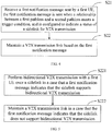
- FIG. 4 is a flowchart of an optional method for data transmission link maintenance according to an embodiment of the present disclosure. As shown in FIG. 4 , in a possible implementation, a process of maintaining a data transmission link by second UE may specifically include the following steps:
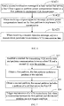
- FIG. 5 is a flowchart of an optional method for data transmission link maintenance according to an embodiment of the present disclosure. As shown in FIG. 5 , step S22 may specifically include the following steps:
- unidirectional V2X data transmission may be originally performed over the sidelink.
- the trigger condition for sending the first notification message may be that the first pathloss is less than the second pathloss by a second threshold.
- a pathloss of the sidelink may be less than a pathloss of a cell that serves the first UE.
- the sidelink may change from supporting unidirectional V2X transmission to supporting bidirectional V2X transmission.
- the second UE can still normally perform unidirectional V2X transmission to the first UE over the sidelink. Therefore, the first notification message may indicate that the sidelink supports bidirectional V2X transmission or directly indicate that the first pathloss is less than the second pathloss by the second threshold.
- the second UE may enter a state of performing bidirectional V2X transmission with the first UE over the sidelink.
- bidirectional V2X data transmission may be performed over the sidelink.
- the trigger condition for sending the first notification message may be that the first pathloss is greater than the second pathloss by a first threshold.
- the pathloss of the sidelink may be greater than the pathloss of the cell that serves the first UE.
- the sidelink may change from supporting bidirectional V2X transmission to supporting unidirectional V2X transmission.
- the first UE may no longer be able to send data or feedback data to the second UE. Therefore, the first notification message may indicate that the sidelink may no longer be able to support bidirectional V2X transmission or directly indicate that the first pathloss is greater than the second pathloss by the first threshold.
- the second UE may take corresponding measures to maintain the V2X transmission link.
- the second UE may maintain the V2X transmission link in the following manner.
- the second UE sends to-be-transmitted data to the first UE immediately after receiving the first notification message.
- the sidelink may still be able to support bidirectional V2X transmission.
- the second UE may obtain transmission resources and transmit the to-be-transmitted data to the first UE as soon as possible.
- the second UE may receive feedback data from the first UE because the sidelink may still be able to support bidirectional V2X transmission.
- the second UE may maintain the V2X transmission link in the following manner: After receiving the first notification message, the second UE enters a state of performing unidirectional V2X transmission to the first UE, that is, gives up bidirectional V2X transmission with the first UE, switches to unidirectional V2X transmission to ensure that messages can be normally sent to the first UE, and does not expect feedback messages.
- the second UE may maintain the V2X transmission link in the following manner: After receiving the first notification message, the second UE releases the sidelink to avoid wasting resources for communication over the sidelink that does not support bidirectional V2X transmission and save resources as much as possible.
- the second UE may maintain the V2X transmission link in the following manner: after receiving the first notification message, the second UE switches to a link at a different carrier frequency to perform bidirectional V2X transmission with the first UE. If the second UE finds that the current sidelink may no longer be able to support bidirectional V2X transmission, the second UE may detect current transmitting frequencies.
- the second UE finds that there is another frequency at which the second UE can perform bidirectional V2X transmission with the first UE, the second UE notifies the first UE to switch to the another frequency for communication.
- the second UE may detect whether the sidelink at the frequency is suitable for V2X transmission.
- the manner in which the second UE notifies the first UE to switch to another frequency is not limited. In an example, the second UE may use RRC signaling on the current sidelink to notify the first UE to switch to another frequency.
- the entity for maintaining the V2X transmission link may be a base station that serves the first UE or the first UE.
- the first UE may send a second notification message to the base station that serves the first UE to notify that the first pathloss is less than the second pathloss by the second threshold, or request the base station to allow the first UE to perform power compensation for sidelink transmission based on the first pathloss, and determine, based on feedback from the base station, an entity for ultimately maintaining the V2X transmission link.
- the first UE may not send a request message to the base station, but directly maintain the V2X transmission link by adjusting a transmission parameter.
- FIG. 6 is a flowchart of an optional method for data transmission link maintenance according to an embodiment of the present disclosure. As shown in FIG. 6 , step S14 may specifically include the following steps:
- unidirectional V2X transmission may be originally performed over the sidelink, and the first pathloss may be greater than the second pathloss.
- the first UE expects to perform bidirectional V2X transmission with the second UE.
- the trigger condition may be met. That is, the first pathloss is less than the second pathloss by the second threshold. If the second threshold is a positive value, the first pathloss may be less than the second pathloss, and the first UE may perform power compensation based on the first pathloss even if the first UE does not send the second notification message to the base station, to enter the bidirectional V2X transmission state.
- the first pathloss may be greater than or equal to the second pathloss, and the first UE cannot directly perform power compensation based on the first pathloss, and needs to send the second notification message to the base station to request to perform power compensation based on the first pathloss. If the base station approves the request of the first UE, the sidelink can enter the bidirectional V2X transmission state as soon as possible to implement the maintenance of the V2X transmission link.
- the first UE may properly adjust the transmission parameter to maintain the V2X transmission link, to enter the bidirectional V2X transmission state as soon as possible, or may not adjust the transmission parameter and wait for the first pathloss to further change to be less than the second pathloss to enter the bidirectional V2X transmission state.
- bidirectional V2X transmission may be originally performed over the sidelink, and the first pathloss may be less than the second pathloss.
- the first UE and the second UE normally perform bidirectional communication with feedback.
- the trigger condition may be met. That is, the first pathloss is greater than the second pathloss by the first threshold. If the first threshold is a non-negative value, the first pathloss may be greater than the second pathloss, and the sidelink may no longer be able to support bidirectional V2X transmission.
- the first UE may send a request message to the base station to request the base station to allow the first UE to perform power compensation based on the first pathloss, such that when the first pathloss is greater than the second pathloss, the sidelink may support bidirectional V2X transmission. If the base station approves the request of the first UE, even if the pathlosses further change and the first pathloss continues to be greater than the second pathloss, the bidirectional V2X transmission between the first UE and the second UE can still be maintained, and the V2X transmission link is maintained. If the base station rejects the request of the first UE, the sidelink may no longer be able to support bidirectional V2X transmission. The first UE can properly adjust the transmission parameter to maintain the V2X transmission link.
- the first pathloss may be less than the second pathloss, such that the first UE can still maintain bidirectional V2X transmission with the second UE, but may be about to enter a situation where the bidirectional transmission cannot be continued.
- the first UE may send the second notification message to the base station to request to perform power compensation based on the first pathloss. If the base station approves the request of the first UE, even if the first pathloss subsequently changes to be greater than the second pathloss, bidirectional V2X transmission can still be perform between the first UE and the second UE. If the base station rejects the request of the first UE, the first UE can appropriately adjust the transmission parameter to maintain the V2X transmission link, to avoid the situation where the bidirectional V2X transmission cannot be continued due to changes in the pathlosses.
- the base station may indicate that the first UE is allowed to perform power compensation based on the first pathloss to transmit V2X data; or configure dedicated transmission resources for the first UE, such that the first UE can use higher transmission power to perform V2X transmission.
- the latter one can also be interpreted as the base station approves the request of the first UE.
- the first UE may directly release the current sidelink, or adjust the transmission parameter to maintain the V2X transmission link.
- the first UE may adjust the transmission parameter to maintain the V2X transmission link in the following manner:
- the first UE adjusts an MCS to maintain the V2X transmission link.
- the method for adjusting the MCS is not specifically limited, and can be flexibly adjusted based on actual situations.
- MCS ranges in different pathloss scenarios may be configured over a network.
- the specific configuration method over the network is not limited and can be flexibly selected based on actual situations.
- the MCS range may be configured by using a system message. In an example, the MCS range may be configured by using dedicated signaling. A correspondence between the MCS range and the pathloss scenario is also not limited. In an example, the MCS range may be configured based on the relationship between the first pathloss and the second pathloss. Correspondences between different pathloss scenarios and the MCS ranges may be as follows: when the second pathloss is greater than the first pathloss, an MCS range 1 is configured for the PSSCH, and specific range values are not limited herein. If the second pathloss is less than the first pathloss, an MCS range 2 is configured for the PSSCH, and specific range values are not limited herein.
- the first UE may adjust the transmission parameter to maintain the V2X transmission link in the following manner: the first UE sends a feedback message to the second UE to maintain the V2X transmission link.
- the form of the feedback message is not specifically limited, provided that the feedback message can be used to indicate a status of the sidelink.
- the feedback message is a sidelink feedback message. Therefore, the first UE may send the sidelink feedback message to the second UE to maintain the V2X transmission link.
- the sidelink feedback message is used to indicate the status of the sidelink (which may indicate that the sidelink meets the trigger condition).
- the feedback message may be SCI. Therefore, the first UE may send the SCI to the second UE to maintain the V2X transmission link.
- the SCI is used to indicate the status of the sidelink.
- the first UE may adjust the transmission parameter to maintain the V2X transmission link in the following manner: the first UE selects a link at a different carrier frequency to perform V2X transmission with the second UE to maintain the V2X transmission link.
- the manner in which the first UE selects the link at the different carrier frequency is not limited.
- the first UE may detect each transmitting frequency of the second UE. If the first UE finds that there is a sidelink that supports bidirectional V2X transmission at another frequency, the first UE notifies the second UE over the sidelink at the another frequency that bidirectional V2X transmission cannot be continued over the original sidelink.
- a manner in which the first UE sends a notification to the second UE over the sidelink is not limited.
- the first UE sends the notification to the second UE by using RRC signaling.
- the notification may indicate a frequency at which transmission is performed when the relationship between the first pathloss and the second pathloss meets the trigger condition, it is assumed that the RRC signaling can be transmitted at any carrier frequency in this example.
- the first UE may adjust the transmission parameter to maintain the V2X transmission link in the following manner: the first UE instructs the second UE to release the sidelink.
- the three maintenance processes in which the first UE maintains the V2X transmission link, the second UE maintains the V2X transmission link, and the base station maintains the V2X transmission link may be simultaneously performed.
- a number and combination of specific parallel maintenance processes are not limited.
- the first UE when the first UE sends the first notification message to the second UE, and the second UE maintains the V2X transmission link after receiving the first notification message, the first UE may simultaneously maintain the V2X transmission link by adjusting the transmission parameter.
- the second UE sends transmission information to the first UE as soon as possible after receiving the first notification message the first UE may simultaneously adjust the MCS range based on the relationship between the first pathloss and the second pathloss.
- the notification message is sent when the relationship between the first pathloss and the second pathloss meets the trigger condition, or a difference between the first pathloss and the second pathloss reaches a third threshold.
- a value and positive or negative of the third threshold are not limited. In this example, whether the first UE and the second UE originally perform unidirectional V2X transmission or bidirectional V2X transmission is no longer considered. Regardless of an original communication status, if the difference between the first pathloss and the second pathloss reaches the third threshold, that is, the first pathloss may be greater or less than the second pathloss, it is considered that a status of the V2X transmission link between the first UE and the second UE may change.
- the maintenance of the V2X transmission link may be triggered.
- the entity for maintaining the V2X transmission link and the specific maintenance method are selected based on actual situations. Reference may be made to the maintenance entity and method mentioned in the foregoing descriptions, and details are not described herein again.
- the maintenance of the V2X transmission link is directly triggered based on the relationship between the first pathloss and the second pathloss. Because the first pathloss and the second pathloss may jitter, such a triggering method may increase instability of the V2X transmission link. Therefore, in this example, to reduce jitters, a measurement trigger time TimeToTrigger is introduced.
- the first UE needs to measure that the difference between the first pathloss and the second pathloss reaches the third threshold, and a duration is greater than or equal to the fourth threshold, namely, the specified measurement trigger time, and then the first UE can send a notification message to maintain the V2X transmission link.
- the specific maintenance method is not repeated herein.
- the setting of the measurement trigger time, namely, the fourth threshold is not specifically limited, and can be flexibly selected based on actual situations.
- FIG. 7 is a flowchart of a method for triggering data transmission link maintenance according to an embodiment of the present disclosure. As shown in FIG. 7 , in a possible implementation, the method may include the following steps:
- the sidelink, the first pathloss, the second pathloss, and the trigger condition in the foregoing steps are the same as the related content mentioned in the method for data transmission link maintenance, and details are not described herein again.
- the entity for setting the trigger condition in the foregoing triggering method is not limited.
- the trigger condition of the triggering method may be set by the second UE, regardless of whether the sidelink is in a unidirectional V2X transmission state or bidirectional V2X transmission state.
- the second UE may set the trigger condition of the triggering method for the first UE when establishing an initial connection of the sidelink with the first UE.
- the setting method is not limited.
- the second UE may set the trigger condition by transmitting RRC signaling over the sidelink.
- the trigger condition of the triggering method can be set by a cell that serves the first UE.
- the specific setting form is not limited.
- the cell that serves the first UE sets the trigger condition by using a system message.
- the cell that serves the first UE sets the trigger condition for the first UE in connected state by using RRC signaling.
- the method for triggering data transmission link maintenance can help the UE to predict link imbalance that the sidelink may encounter in advance, to trigger the maintenance of the data transmission link in time.
- the V2X transmission can be ensured whenever possible.
- various maintenance forms between multiple entities can ensure that the V2X transmission can be normally performed whenever possible.
- the triggering method and maintenance method can make the bidirectional V2X transmission continue whenever possible.
- the triggering method and maintenance method can make the UE enters a state of bidirectional V2X transmission as soon as possible if required, and ensure communication requirements of the UE as much as possible.
- FIG. 8 is a block diagram of an apparatus for data transmission link maintenance according to an embodiment of the present disclosure. As shown in FIG. 8 , the apparatus 40 includes the following units:
- a sidelink establishment unit 41 configured to establish a sidelink for transmitting V2X service data and perform communication between first UE and second UE over the sidelink.
- a first obtaining unit 42 configured to obtain a first pathloss.
- a second obtaining unit 43 configured to obtain a second pathloss.
- a maintenance unit 44 configured to maintain a V2X transmission link when a relationship between the first pathloss and the second pathloss meets a trigger condition.
- the maintaining a V2X transmission link when a relationship between the first pathloss and the second pathloss meets a trigger condition may specifically include: maintaining the V2X transmission link when the first pathloss is greater than the second pathloss by a first threshold; or maintaining the V2X transmission link when the first pathloss is less than the second pathloss by a second threshold.
- the maintenance unit 44 may be specifically configured to: send a first notification message to the second UE, such that the second UE maintains the V2X transmission link based on the first notification message; send a second notification message to a base station that serves the first UE to maintain the V2X transmission link; or adjust a transmission parameter to maintain the V2X transmission link.
- the maintenance unit 44 may be further configured to: send the second notification message to the base station to request to perform power compensation based on the first pathloss to implement V2X transmission; and when receiving a request approval message, perform power compensation based on the first pathloss to implement V2X transmission; or when receiving a request rejection message, adjust the transmission parameter to maintain the V2X transmission link.
- the adjusting a transmission parameter to maintain the V2X transmission link may specifically include: adjusting an MCS to maintain the V2X transmission link; sending a feedback message to the second UE to maintain the V2X transmission link; selecting a link at a different carrier frequency to perform V2X transmission with the second UE to maintain the V2X transmission link; or instructing the second UE to release the sidelink.
- the sending a notification message when a relationship between the first pathloss and the second pathloss meets a trigger condition further may specifically include: sending the notification message when a difference between the first pathloss and the second pathloss reaches a third threshold; or sending the notification message when the difference between the first pathloss and the second pathloss reaches the third threshold and a duration exceeds a fourth threshold.
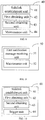
- FIG. 9 is a block diagram of an apparatus for data transmission link maintenance according to an embodiment of the present disclosure. As shown in FIG. 9 , the apparatus 50 includes the following units:
- a first notification message receiving unit 51 configured to receive a first notification message sent by first UE, the first notification message is sent when a relationship between a first pathloss and a second pathloss meets a trigger condition, and is used to indicate a status of a sidelink for V2X transmission.
- a maintenance unit 52 configured to maintain a V2X transmission link based on the first notification message.
- the maintenance unit 52 may be specifically configured to: perform bidirectional V2X transmission with the first UE over the sidelink if the first notification message indicates that the sidelink supports bidirectional V2X transmission; or maintain the V2X transmission link if the first notification message indicates that the sidelink does not support bidirectional V2X transmission.
- FIG. 10 is a block diagram of an apparatus for triggering data transmission link maintenance according to an embodiment of the present disclosure. As shown in FIG. 10 , the apparatus 60 includes the following units:
- a sidelink establishment unit 61 configured to establish a sidelink for transmitting V2X service data and perform communication between first UE and second UE over the sidelink.
- a first obtaining unit 62 configured to obtain a first pathloss.
- a second obtaining unit 63 configured to obtain a second pathloss.
- a trigger unit 64 configured to trigger maintenance of a V2X transmission link when a relationship between the first pathloss and the second pathloss meets a trigger condition.
- the trigger unit 64 may be specifically configured to: trigger the maintenance of the V2X transmission link when the first pathloss is greater than the second pathloss by a first threshold; or trigger the maintenance of the V2X transmission link when the first pathloss is less than the second pathloss by a second threshold.
- FIG. 11 is a schematic diagram of an application example of the present disclosure.
- the application example is only for facilitating the understanding of the embodiments of the present disclosure, and does not limit the embodiments of the present disclosure.
- Rx UE is located in a cell Cell2, UE 1 is located in a cell Cell1, and the Rx UE and the UE 1 are in a bidirectional V2X transmission state.
- a distance between the Rx UE and the UE 1 is relatively short, a relationship between a pathloss PL3 of a sidelink between the Rx UE and the UE 1 and a pathloss PL2 of the cell Cell2 where the Rx UE is located meets the following condition: PL3 ⁇ PL2.
- the Rx UE performs power compensation based on the pathloss PL3.
- the Rx UE can serve as a receiver to receive V2X data sent by the UE 1, and can also serve as a transmitter to send data or feedback data to UE 1, to implement bidirectional V2X transmission. It can be learned from FIG. 11 that when the two UE perform bidirectional V2X transmission, the Rx UE is moving in a direction far away from the UE 1 and close to a base station in the cell Cell2. Because the distance between the Rx UE and the UE 1 and a distance between the Rx UE and the base station in the cell Cell2 may change, the values of PL2 and PL3 may also change accordingly. If the condition PL3 > PL2 is met, the Rx UE may perform power compensation based on PL2. Consequently, data sent by the Rx UE as a sender may not be received by the UE 1, and bidirectional V2X transmission cannot be maintained.
- the Rx UE can continuously measure the values of PL3 and PL2 when the Rx UE is moving. If PL3 is greater than PL2 by a preset offset, the Rx UE triggers maintenance of a V2X transmission link. In this application example, the offset is set to -2 dB. In other words, if PL3 is greater than PL2 by -2 dB, the maintenance of the V2X transmission link is triggered.
- PL3 is still less than PL2.
- PL3 is less than PL2 by only 2 dB, and is about to be greater than PL2, and it is likely to be unable to maintain bidirectional V2X transmission.
- the Rx UE may perform the following operations: the Rx UE may send a notification message to the UE 1 to notify that the current sidelink for bidirectional V2X transmission may no longer be able to support bidirectional transmission. If the Rx UE is in connected state, the Rx UE may send a request to the base station in the cell Cell2 to maintain the bidirectional transmission.
- the foregoing two operations can be performed separately or simultaneously, and can be flexibly selected based on actual situations.
- the UE 1 may obtain transmission resources and transmit the to-be-transmitted data to the Rx UE as soon as possible. Alternatively, the UE 1 may switch to unidirectional transmission without feedback. Alternatively, the UE 1 may release the current PC5 link. Alternatively, if the UE 1 finds that there is another frequency at which the UE 1 can perform V2X transmission with the Rx UE, the UE 1 uses PC5 RRC signaling to notify the Rx UE to switch to the another frequency to continue the V2X transmission. To find that there is the another frequency at which the UE 1 can perform V2X transmission with the Rx UE, the UE 1 may need to detect whether there are transmission resources at the another frequency and whether a sidelink at the another frequency is suitable for V2X transmission.
- the base station may indicate whether the Rx UE is allowed to transmit V2X data by using a pathloss greater than PL2, or the base station may configure dedicated transmission resources for the Rx UE, such that V2X transmission can be performed at higher transmission power.
- the Rx UE finds it possible to transmit V2X data by using PL3. In this case, the Rx UE may perform the following operations to maintain the V2X transmission link whenever possible:
- the Rx UE may adjust an MCS to transmit V2X data.
- MCS ranges in different pathloss scenarios can be configured over a network (by using a system message or dedicated signaling) as follows:
- the Rx UE may only send feedback information or SCI to indicate that V2X data transmission cannot be performed.
- the Rx UE indicates an issue of the current sidelink to the UE 1 over the sidelink at the another carrier frequency.
- the foregoing operations of the Rx UE may be performed after the base station rejects the request of the Rx UE, when the Rx UE sends the message to the UE 1 or the base station, or when the Rx UE maintains the V2X transmission link with the UE 1 or the base station.
- This is not specifically limited.
- the operations can be flexibly selected based on actual situations.
- the bidirectional V2X transmission between the Rx UE and the UE 1 can be maintained whenever possible, to improve communication stability.
- FIG. 12 is a schematic diagram of an application example of the present disclosure.
- the application example is only for facilitating the understanding of the embodiments of the present disclosure, and does not limit the embodiments of the present disclosure.
- Rx UE is located in a cell Cell2, and UE 1 is located in a cell Cell1.
- the Rx UE and the UE 1 are in a unidirectional V2X transmission state.
- the UE 1 sends transmission data to the Rx UE, and the Rx UE can receive the transmission data, but cannot send data or feedback data to the UE 1.
- a distance between the Rx UE and the UE 1 is relatively long, a relationship between a pathloss PL3 of a sidelink between the Rx UE and the UE 1 and a pathloss PL2 of the cell Cell2 where the Rx UE is located meets the following condition: PL3 > PL2.
- the Rx UE performs power compensation based on the pathloss PL2. Therefore, the Rx UE can serve only as a receiver to receive V2X data sent by the UE 1 to implement unidirectional V2X transmission. It can be learned from FIG. 12 that when the two UE perform unidirectional V2X transmission, the Rx UE is moving in a direction close to the UE 1 and far away from a base station in the cell Cell2. Because the distance between the Rx UE and the UE 1 and a distance between the Rx UE and the base station in the cell Cell2 may change, the values of PL2 and PL3 may also change accordingly. If the condition PL3 ⁇ PL2 is met, the Rx UE may perform power compensation based on PL3 to enter a bidirectional V2X transmission state.
- the Rx UE can continuously measure the values of PL3 and PL2 when the Rx UE is moving. If PL3 is less than PL2 by a preset offset, the Rx UE triggers maintenance of a V2X transmission link to enter the bidirectional V2X transmission state as soon as possible.
- the offset is set to -3 dB.
- the Rx UE may prepare to transmit V2X data to the UE 1, or send a request to the base station to request the base station to allocate resources for transmitting V2X data to the UE 1.
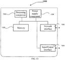
- FIG. 13 is a block diagram of an apparatus for data transmission link maintenance 1300 according to an exemplary embodiment.
- An apparatus for triggering data transmission link maintenance is also provided, and may be included in the apparatus 1300 in FIG. 13 .
- the apparatus 1300 may be provided as a server.
- the apparatus 1300 includes a processing component 1322, which further includes one or more processors; and a memory resource represented by a memory 1332, for storing instructions executable by the processing component 1322, such as an application program.
- the application program stored in the memory 1332 may include one or more modules each corresponding to a set of instructions.
- the processing component 1322 is configured to execute the instructions to perform the foregoing method.
- the apparatus 1300 may further include a power supply component 1326 configured to perform power management of the apparatus 1300, a wired or wireless network interface 1350 configured to connect the apparatus 1300 to a network, and an input/output (I/O) interface 1358.
- the apparatus 1300 can operate based on an operating system stored in the memory 1332, such as Windows ServerTM, Mac OS XTM, UnixTM, LinuxTM, FreeBSDTM, or the like.
- a non-volatile computer-readable storage medium includes the memory 1332 including a computer program instruction.
- the computer program instruction can be executed by the processing component 1322 of the apparatus 1300 to perform the foregoing method.
- the present disclosure may be a system, method, and/or computer program product.
- the computer program product may include a computer-readable storage medium storing a computer-readable program instruction for enabling a processor to implement various aspects of the present disclosure.
- the computer-readable storage medium may be a tangible device that can hold and store an instruction used by an instruction execution device.
- the computer-readable storage medium may be, for example, but not limited to, an electrical storage device, a magnetic storage device, an optical storage device, an electromagnetic storage device, a semiconductor storage device, or any suitable combination of the foregoing devices.
- the computer-readable storage medium includes: a portable computer disk, a hard disk, a random access memory (RAM), a read-only memory (ROM), an erasable programmable ROM (EPROM), a flash memory, a static RAM (SRAM), a compact disc ROM (CD-ROM), a digital versatile disc (DVD), a memory stick, a floppy disk, and a mechanical encoding device such as a protruding structure that stores an instruction in a hole card or a groove, and any suitable combination of the foregoing.
- the computer-readable storage medium herein is not interpreted as a transient signal, such as radio waves or other freely propagating electromagnetic waves, electromagnetic waves propagating through waveguides or other transmission media, such as light pulses through fiber optic cables, or electrical signals propagating through wires.
- the computer-readable program instruction described herein can be downloaded from the computer-readable storage medium to various computing/processing devices, or downloaded to an external computer or external storage device over a network, such as the Internet, a local area network, a wide area network, and/or a wireless network.
- the network may include a copper transmission cable, optical fiber transmission, wireless transmission, a router, a firewall, a switch, a gateway computer, and/or an edge server.
- the network adapter card or network interface in each computing/processing device receives the computer-readable program instruction from the network, and forwards the computer-readable program instruction for storage in the computer-readable storage medium in each computing/processing device.
- the computer program instruction used to perform the operations of the present disclosure may be an assembly instructions, an instruction set architecture (ISA) instruction, a machine instruction, a machine-related instruction, microcode, a firmware instruction, a state setting data, or source code or target code written in any combination of one or more programming languages.
- the programming languages include object-oriented programming languages such as Smalltalk and C++, and conventional procedural programming languages such as C language or similar programming languages.
- the computer-readable program instruction can be executed fully on a user computer, executed partially on a user computer, executed as an independent software package, executed partially on a user computer and partially on a remote computer, or executed fully on a remote computer or a server.
- the remote computer may be connected to a user computer over any type of network, including a local area network or a wide area network, or may be connected to an external computer (for example, connected over the Internet by using an Internet service provider).
- an electronic circuit such as a programmable logic circuit, a field programmable gate array (FPGA), or a programmable logic array (PLA), can be customized by using status information of the computer-readable program instruction.
- the computer-readable program instruction is executed to implement various aspects of the present disclosure.
- the computer-readable program instructions can be provided to a processor of a general-purpose computer, a dedicated computer, or other programmable data processing device, to produce a machine that makes the instruction when executed by the processor of the computer or other programmable data processing devices to implement the functions/actions specified in one or more blocks in the flowcharts and/or block diagrams.
- the computer-readable program instructions may be stored in a computer-readable storage medium. These instructions make computers, programmable data processing apparatuses, and/or other devices work in a specific manner.
- the computer-readable medium storing the instructions includes an artifact, which includes instructions for implementing various aspects of the functions/actions specified in one or more blocks in the flowcharts and/or block diagrams.
- the computer-readable program instructions may be loaded onto a computer, another programmable data processing apparatus, or another device, such that a series of steps are executed on the computer, another programmable data processing apparatus, or another equipment to produce a computer-implemented process.
- the instructions executed on the computer, another programmable data processing apparatus, or another device implement the functions/actions specified in one or more blocks in the flowcharts and/or block diagrams.
- each block in the flowcharts or block diagrams may represent a module, a program segment, or a part of code, and the module, the program segment, or the part of code contains one or more executable instructions used to implement specified logical functions.
- functions marked in the blocks may also take place in an order different from the order marked in the accompanying drawings. For example, two consecutive blocks can actually be executed in parallel, or sometimes can be executed in the reverse order, depending on the functions involved.
- each block in the flowcharts and/or block diagrams and combinations of the blocks in the flowcharts and/or block diagrams may be implemented by a dedicated hardware-based system for executing specified functions or operations, or may be implemented by a combination of dedicated hardware and computer instructions.
Landscapes
- Engineering & Computer Science (AREA)
- Computer Networks & Wireless Communication (AREA)
- Signal Processing (AREA)
- Mobile Radio Communication Systems (AREA)
Applications Claiming Priority (2)
| Application Number | Priority Date | Filing Date | Title |
|---|---|---|---|
| CN201910008487.0A CN111294765B (zh) | 2019-01-04 | 2019-01-04 | 一种数据传输链路的维护、维护触发方法及装置 |
| PCT/CN2020/070251 WO2020140968A1 (zh) | 2019-01-04 | 2020-01-03 | 一种数据传输链路的维护、维护触发方法及装置 |
Publications (2)
| Publication Number | Publication Date |
|---|---|
| EP3908014A1 true EP3908014A1 (de) | 2021-11-10 |
| EP3908014A4 EP3908014A4 (de) | 2022-10-12 |
Family
ID=71018707
Family Applications (1)
| Application Number | Title | Priority Date | Filing Date |
|---|---|---|---|
| EP20735980.3A Withdrawn EP3908014A4 (de) | 2019-01-04 | 2020-01-03 | Verfahren zur wartung einer datenübertragungsverbindung, verfahren zur auslösung der wartung und vorrichtung |
Country Status (4)
| Country | Link |
|---|---|
| US (1) | US20220061120A1 (de) |
| EP (1) | EP3908014A4 (de) |
| CN (1) | CN111294765B (de) |
| WO (1) | WO2020140968A1 (de) |
Families Citing this family (5)
| Publication number | Priority date | Publication date | Assignee | Title |
|---|---|---|---|---|
| US11601893B2 (en) * | 2019-08-15 | 2023-03-07 | Qualcomm Incorporated | Sidelink coordination for power control |
| US11799710B2 (en) * | 2020-12-10 | 2023-10-24 | Qualcomm Incorporated | Techniques for signaling a source of dominant noise at a user equipment |
| US20220225283A1 (en) * | 2021-01-14 | 2022-07-14 | Apple Inc. | Systems and methods for enhancement on sidelink power control |
| WO2025035300A1 (zh) * | 2023-08-11 | 2025-02-20 | Oppo广东移动通信有限公司 | 侧行通信方法及终端设备 |
| CN120017576A (zh) * | 2023-11-15 | 2025-05-16 | 华为技术有限公司 | 一种通信方法及装置 |
Family Cites Families (15)
| Publication number | Priority date | Publication date | Assignee | Title |
|---|---|---|---|---|
| WO2007024096A2 (en) * | 2005-08-24 | 2007-03-01 | Electronics And Telecommunications Research Institute | Communication resource allocation method of base station |
| CN103139889B (zh) * | 2011-11-28 | 2015-09-09 | 华为技术有限公司 | D2d的功率控制方法、用户设备、基站和通讯系统 |
| US9338807B2 (en) * | 2012-03-19 | 2016-05-10 | Futurewei Technologies, Inc. | System and method for direct mobile communications power control |
| US9084203B2 (en) * | 2012-05-21 | 2015-07-14 | Qualcomm Incorporated | Methods and apparatus for providing transmit power control for devices engaged in D2D communications |
| CN102821391B (zh) * | 2012-09-14 | 2015-01-14 | 电子科技大学 | 基于距离比的d2d链路频谱分配方法 |
| CN103929755A (zh) * | 2013-01-15 | 2014-07-16 | 华为技术有限公司 | 一种通信方法及装置 |
| CN104066126B (zh) * | 2013-03-18 | 2017-10-20 | 电信科学技术研究院 | 一种进行d2d切换的方法、系统和设备 |
| US10051507B2 (en) * | 2013-07-03 | 2018-08-14 | Mediatek Inc. | Traffic shaping mechanism for UE power saving in idle mode |
| CN105246141B (zh) * | 2014-07-11 | 2018-10-12 | 中国人民解放军理工大学 | 基于地理频谱数据库的多对终端直通链路联合功率控制方法 |
| CN105323839A (zh) * | 2014-07-28 | 2016-02-10 | 宇龙计算机通信科技(深圳)有限公司 | 资源配置方法及配置系统、基站和终端 |
| CN105813186B (zh) * | 2014-12-31 | 2019-11-22 | 上海诺基亚贝尔股份有限公司 | 一种为用户设备确定发射功率的方法、装置与系统 |
| WO2016134755A1 (en) * | 2015-02-24 | 2016-09-01 | Huawei Technologies Co., Ltd. | Communication devices, control device and methods thereof |
| CN108632973B (zh) * | 2017-03-24 | 2021-08-31 | 上海诺基亚贝尔股份有限公司 | 用于在通信系统中控制功率的方法和设备 |
| CN110603880A (zh) * | 2017-05-05 | 2019-12-20 | 华为技术有限公司 | 半持续调度方法、用户设备和网络设备 |
| CN108391308A (zh) * | 2017-08-22 | 2018-08-10 | 南京邮电大学 | 一种毫米波蜂窝网络中d2d通信的资源分配和功率控制方法 |
-
2019
- 2019-01-04 CN CN201910008487.0A patent/CN111294765B/zh active Active
-
2020
- 2020-01-03 EP EP20735980.3A patent/EP3908014A4/de not_active Withdrawn
- 2020-01-03 WO PCT/CN2020/070251 patent/WO2020140968A1/zh not_active Ceased
- 2020-01-03 US US17/420,354 patent/US20220061120A1/en not_active Abandoned
Also Published As
| Publication number | Publication date |
|---|---|
| WO2020140968A1 (zh) | 2020-07-09 |
| US20220061120A1 (en) | 2022-02-24 |
| CN111294765B (zh) | 2021-10-08 |
| CN111294765A (zh) | 2020-06-16 |
| EP3908014A4 (de) | 2022-10-12 |
Similar Documents
| Publication | Publication Date | Title |
|---|---|---|
| EP3908014A1 (de) | Verfahren zur wartung einer datenübertragungsverbindung, verfahren zur auslösung der wartung und vorrichtung | |
| KR102878969B1 (ko) | 안테나 패널의 응용 방법, 장치 및 저장 매체 | |
| US10827501B2 (en) | Techniques for providing proximity services (ProSe) priority-related information to a base station in a wireless network | |
| CN108541383B (zh) | 用于触发用户设备(ue)到网络中继指示的传输的方法 | |
| US10945176B2 (en) | Method, device and computer program for primary cell change | |
| WO2021128931A1 (zh) | 跨载波调度方法、装置及存储介质 | |
| KR20230129602A (ko) | 수신된 안테나 포트 고유의 조정을 이용하여 안테나 포트를 선택하기 위한 방법 및 장치 | |
| US20210029643A1 (en) | 5G NR Fast Low-Power Mode | |
| US12047926B2 (en) | Multi-carrier data transmission method and apparatus | |
| CN113365315A (zh) | 信关站切换方法及装置 | |
| WO2021148040A1 (zh) | 信道监听的指示方法、装置及存储介质 | |
| JP7544356B2 (ja) | 通信装置及び通信方法 | |
| WO2022206377A1 (zh) | 用于小区选择的方法、设备、存储介质和计算机程序产品 | |
| CN111600687B (zh) | 一种降低干扰的方法及设备 | |
| CN114614956B (zh) | 电池感知载波激活 | |
| CN115836489B (zh) | 用于通信的装置、方法和计算机程序产品 | |
| US20210250834A1 (en) | Attenuating a Signal from a Cell, Beam or Frequency in a Resource | |
| US20250113363A1 (en) | Skipping transmission of uplink control information | |
| WO2025208643A1 (en) | Conditional transmission of application layer data reports | |
| US20220303832A1 (en) | Communication device and communication method | |
| CN121057035A (zh) | 通信方法、用户设备及基站 | |
| WO2024235524A1 (en) | Determining uplink grant during cell discontinuous transmission | |
| CN120786667A (zh) | 波束管理 | |
| WO2019104593A1 (en) | Methods and apparatus for reducing transmit power of a cell transmitter | |
| NZ750321B2 (en) | Method, device and computer program for primary cell change |
Legal Events
| Date | Code | Title | Description |
|---|---|---|---|
| STAA | Information on the status of an ep patent application or granted ep patent |
Free format text: STATUS: THE INTERNATIONAL PUBLICATION HAS BEEN MADE |
|
| PUAI | Public reference made under article 153(3) epc to a published international application that has entered the european phase |
Free format text: ORIGINAL CODE: 0009012 |
|
| STAA | Information on the status of an ep patent application or granted ep patent |
Free format text: STATUS: REQUEST FOR EXAMINATION WAS MADE |
|
| 17P | Request for examination filed |
Effective date: 20210804 |
|
| AK | Designated contracting states |
Kind code of ref document: A1 Designated state(s): AL AT BE BG CH CY CZ DE DK EE ES FI FR GB GR HR HU IE IS IT LI LT LU LV MC MK MT NL NO PL PT RO RS SE SI SK SM TR |
|
| DAV | Request for validation of the european patent (deleted) | ||
| DAX | Request for extension of the european patent (deleted) | ||
| A4 | Supplementary search report drawn up and despatched |
Effective date: 20220914 |
|
| RIC1 | Information provided on ipc code assigned before grant |
Ipc: H04W 76/30 20180101ALN20220908BHEP Ipc: H04W 76/25 20180101ALN20220908BHEP Ipc: H04L 43/16 20220101ALN20220908BHEP Ipc: H04L 43/0823 20220101ALN20220908BHEP Ipc: H04W 52/24 20090101ALN20220908BHEP Ipc: H04W 52/38 20090101ALN20220908BHEP Ipc: H04W 76/14 20180101ALI20220908BHEP Ipc: H04W 4/46 20180101ALI20220908BHEP Ipc: H04L 41/0654 20220101ALI20220908BHEP Ipc: H04W 4/44 20180101AFI20220908BHEP |
|
| STAA | Information on the status of an ep patent application or granted ep patent |
Free format text: STATUS: EXAMINATION IS IN PROGRESS |
|
| 17Q | First examination report despatched |
Effective date: 20231030 |
|
| STAA | Information on the status of an ep patent application or granted ep patent |
Free format text: STATUS: THE APPLICATION IS DEEMED TO BE WITHDRAWN |
|
| 18D | Application deemed to be withdrawn |
Effective date: 20250801 |