EP3907997B1 - Dynamic image encoding device, dynamic image encoding method, dynamic image encoding program, dynamic image decoding device, dynamic image decoding method, and dynamic image decoding program - Google Patents
Dynamic image encoding device, dynamic image encoding method, dynamic image encoding program, dynamic image decoding device, dynamic image decoding method, and dynamic image decoding program Download PDFInfo
- Publication number
- EP3907997B1 EP3907997B1 EP21181798.6A EP21181798A EP3907997B1 EP 3907997 B1 EP3907997 B1 EP 3907997B1 EP 21181798 A EP21181798 A EP 21181798A EP 3907997 B1 EP3907997 B1 EP 3907997B1
- Authority
- EP
- European Patent Office
- Prior art keywords
- block
- prediction
- prediction information
- inter prediction
- subject
- Prior art date
- Legal status (The legal status is an assumption and is not a legal conclusion. Google has not performed a legal analysis and makes no representation as to the accuracy of the status listed.)
- Active
Links
Images




















Classifications
-
- H—ELECTRICITY
- H04—ELECTRIC COMMUNICATION TECHNIQUE
- H04N—PICTORIAL COMMUNICATION, e.g. TELEVISION
- H04N19/00—Methods or arrangements for coding, decoding, compressing or decompressing digital video signals
- H04N19/10—Methods or arrangements for coding, decoding, compressing or decompressing digital video signals using adaptive coding
- H04N19/102—Methods or arrangements for coding, decoding, compressing or decompressing digital video signals using adaptive coding characterised by the element, parameter or selection affected or controlled by the adaptive coding
- H04N19/103—Selection of coding mode or of prediction mode
- H04N19/105—Selection of the reference unit for prediction within a chosen coding or prediction mode, e.g. adaptive choice of position and number of pixels used for prediction
-
- H—ELECTRICITY
- H04—ELECTRIC COMMUNICATION TECHNIQUE
- H04N—PICTORIAL COMMUNICATION, e.g. TELEVISION
- H04N19/00—Methods or arrangements for coding, decoding, compressing or decompressing digital video signals
- H04N19/10—Methods or arrangements for coding, decoding, compressing or decompressing digital video signals using adaptive coding
- H04N19/102—Methods or arrangements for coding, decoding, compressing or decompressing digital video signals using adaptive coding characterised by the element, parameter or selection affected or controlled by the adaptive coding
- H04N19/119—Adaptive subdivision aspects, e.g. subdivision of a picture into rectangular or non-rectangular coding blocks
-
- H—ELECTRICITY
- H04—ELECTRIC COMMUNICATION TECHNIQUE
- H04N—PICTORIAL COMMUNICATION, e.g. TELEVISION
- H04N19/00—Methods or arrangements for coding, decoding, compressing or decompressing digital video signals
- H04N19/10—Methods or arrangements for coding, decoding, compressing or decompressing digital video signals using adaptive coding
- H04N19/134—Methods or arrangements for coding, decoding, compressing or decompressing digital video signals using adaptive coding characterised by the element, parameter or criterion affecting or controlling the adaptive coding
- H04N19/157—Assigned coding mode, i.e. the coding mode being predefined or preselected to be further used for selection of another element or parameter
- H04N19/159—Prediction type, e.g. intra-frame, inter-frame or bidirectional frame prediction
-
- H—ELECTRICITY
- H04—ELECTRIC COMMUNICATION TECHNIQUE
- H04N—PICTORIAL COMMUNICATION, e.g. TELEVISION
- H04N19/00—Methods or arrangements for coding, decoding, compressing or decompressing digital video signals
- H04N19/10—Methods or arrangements for coding, decoding, compressing or decompressing digital video signals using adaptive coding
- H04N19/169—Methods or arrangements for coding, decoding, compressing or decompressing digital video signals using adaptive coding characterised by the coding unit, i.e. the structural portion or semantic portion of the video signal being the object or the subject of the adaptive coding
- H04N19/17—Methods or arrangements for coding, decoding, compressing or decompressing digital video signals using adaptive coding characterised by the coding unit, i.e. the structural portion or semantic portion of the video signal being the object or the subject of the adaptive coding the unit being an image region, e.g. an object
- H04N19/176—Methods or arrangements for coding, decoding, compressing or decompressing digital video signals using adaptive coding characterised by the coding unit, i.e. the structural portion or semantic portion of the video signal being the object or the subject of the adaptive coding the unit being an image region, e.g. an object the region being a block, e.g. a macroblock
-
- H—ELECTRICITY
- H04—ELECTRIC COMMUNICATION TECHNIQUE
- H04N—PICTORIAL COMMUNICATION, e.g. TELEVISION
- H04N19/00—Methods or arrangements for coding, decoding, compressing or decompressing digital video signals
- H04N19/46—Embedding additional information in the video signal during the compression process
- H04N19/463—Embedding additional information in the video signal during the compression process by compressing encoding parameters before transmission
-
- H—ELECTRICITY
- H04—ELECTRIC COMMUNICATION TECHNIQUE
- H04N—PICTORIAL COMMUNICATION, e.g. TELEVISION
- H04N19/00—Methods or arrangements for coding, decoding, compressing or decompressing digital video signals
- H04N19/50—Methods or arrangements for coding, decoding, compressing or decompressing digital video signals using predictive coding
- H04N19/503—Methods or arrangements for coding, decoding, compressing or decompressing digital video signals using predictive coding involving temporal prediction
-
- H—ELECTRICITY
- H04—ELECTRIC COMMUNICATION TECHNIQUE
- H04N—PICTORIAL COMMUNICATION, e.g. TELEVISION
- H04N19/00—Methods or arrangements for coding, decoding, compressing or decompressing digital video signals
- H04N19/50—Methods or arrangements for coding, decoding, compressing or decompressing digital video signals using predictive coding
- H04N19/503—Methods or arrangements for coding, decoding, compressing or decompressing digital video signals using predictive coding involving temporal prediction
- H04N19/51—Motion estimation or motion compensation
-
- H—ELECTRICITY
- H04—ELECTRIC COMMUNICATION TECHNIQUE
- H04N—PICTORIAL COMMUNICATION, e.g. TELEVISION
- H04N19/00—Methods or arrangements for coding, decoding, compressing or decompressing digital video signals
- H04N19/50—Methods or arrangements for coding, decoding, compressing or decompressing digital video signals using predictive coding
- H04N19/503—Methods or arrangements for coding, decoding, compressing or decompressing digital video signals using predictive coding involving temporal prediction
- H04N19/51—Motion estimation or motion compensation
- H04N19/513—Processing of motion vectors
- H04N19/517—Processing of motion vectors by encoding
- H04N19/52—Processing of motion vectors by encoding by predictive encoding
-
- H—ELECTRICITY
- H04—ELECTRIC COMMUNICATION TECHNIQUE
- H04N—PICTORIAL COMMUNICATION, e.g. TELEVISION
- H04N19/00—Methods or arrangements for coding, decoding, compressing or decompressing digital video signals
- H04N19/50—Methods or arrangements for coding, decoding, compressing or decompressing digital video signals using predictive coding
- H04N19/503—Methods or arrangements for coding, decoding, compressing or decompressing digital video signals using predictive coding involving temporal prediction
- H04N19/51—Motion estimation or motion compensation
- H04N19/583—Motion compensation with overlapping blocks
-
- H—ELECTRICITY
- H04—ELECTRIC COMMUNICATION TECHNIQUE
- H04N—PICTORIAL COMMUNICATION, e.g. TELEVISION
- H04N19/00—Methods or arrangements for coding, decoding, compressing or decompressing digital video signals
- H04N19/50—Methods or arrangements for coding, decoding, compressing or decompressing digital video signals using predictive coding
- H04N19/593—Methods or arrangements for coding, decoding, compressing or decompressing digital video signals using predictive coding involving spatial prediction techniques
Definitions
- Coding information relating to inter prediction includes: a prediction mode that differentiate among L0 prediction, L1 prediction, and bi-prediction for each block; a reference index that specifies a reference picture for each reference list of each block; and a motion vector that represents a direction of movement and an amount of movement of a block. This coding information is encoded and/or decoded.
- a direct mode where inter prediction information of a block subject to encoding or decoding is generated from inter prediction information of a decoded block, is defined. Since encoding of inter prediction information is not required, encoding efficiency is improved with the direct mode.
- a picture, of which the reference index of L1 is registered to 0, is used as a base picture colPic.
- a block at a position identical to a block subject to encoding or decoding in the base picture colPic is used as a base block.
- the motion vector of the base block L0 is used as a base motion vector mvCol. If the base block is not encoded by using L0 prediction but encoded by using L1 prediction, the motion vector of L1 of the base block is used as a base motion vector mvCol.
- a picture referred to by the base motion vector mvCol is used as a reference picture of L0 in a time direct mode, and the base picture colPic is used as a reference picture of L1 in a time direct mode.
- POC POC of the reference picture of L0 in a time direct mode
- a motion vector mvL0 of L0 in a time direct mode is derived from a base motion vector mvCol by a scaling computation process.
- mvL 0 tb / td * mvCol
- a moving picture encoding device 1
- a moving picture encoding method 2
- a moving picture encoding program 3
- a moving picture decoding device 4
- a moving picture decoding method 5
- a moving picture decoding program 6
- an amount of generated code of coding information to be transmitted can be reduced and an encoding efficiency can be improved.
- a picture is partitioned in units of squares having a same arbitrary size as shown in Fig. 3 .
- This unit is defined as a tree block and used as a basic unit of managing an address for specifying a block subject to encoding or decoding (Hereinafter, "a block subject to encoding or decoding" refers to a block subject to encoding in case of encoding process, and refers to a block subject to decoding in case of decoding process, unless otherwise noted.) in a picture.
- a tree block comprises one brightness signal and two color-difference signals, except in case of a monochrome.
- a mode is switched between intra prediction (MODE_INTRA) and inter prediction (MODE_INTER) in units of coding blocks.
- intra prediction prediction is performed from a surrounding encoded or decoded picture signals in a picture subject to encoding or decoding
- decoded is used for a decoded picture that has been encoded in a encoding process, a decode prediction block that has been encoded in a encoding process, a decoded picture signal that has been encoded in a encoding process, or the like
- decoded is used for a decoded picture, a decoded prediction block, a decoded picture signal, or the like.
- This mode that distinguishes the intra prediction (MODE_INTRA) and the inter prediction (MODE_INTER) is defined as a prediction mode (PredMode).
- the prediction mode (PredMode) has, as a value, the intra prediction (MODE_INTRA) or the inter prediction (MODE_INTER), and can select a type of prediction so as to perform encoding.
- the 2N by N partition (PART_2NxN) is a partition mode where a block is partitioned with a ratio of 1:1, vertically
- the 2N by nU partition (PART_2NxnU) is a partition mode where a block is partitioned with a ratio of 1:3, vertically
- 2N by nD partition (PART_2NxnD) is a partition mode where a block is partitioned with a ratio of 3:1, vertically.
- Partition modes (PartMode) where a brightness signal of a coding block is partitioned into two prediction blocks arranged horizontally as shown in Fig.
- 4E, 4F, and 4G are defined as N by 2N partition (PART_Nx2N), nL by 2N partition (PART_nLx2N), and nR by 2N partition (PART_nRx2N), respectively.
- the N by 2N partition (PART_Nx2N) is a partition mode where a block is partitioned with a ratio of 1:1, horizontally
- the nL by 2N partition (PART_nLx2N) is a partition mode where a block is partitioned with a ratio of 1:3, horizontally
- nR by 2N partition PART_nRx2N
- a partition mode (PartMode) where a brightness signal of a coding block is partitioned vertically and horizontally into four blocks as shown in Fig. 4H is defined as N by N partition (PART_NxN).
- a number starting from 0 is assigned to a prediction block in the coding block in the order of encoding. This number is defined as a partition index PartIdx.
- a number written in each prediction block in the coding blocks shown in Fig. 4 indicates the partition index PartIdx of the prediction block.
- the partition index PartIdx of an upper prediction block is set to 0 and the partition index PartIdx of a lower prediction block is set to 1.
- the partition index PartIdx of an upper left prediction block is set to 0, the partition index PartIdx of an upper right prediction block is set to 1, the partition index PartIdx of a lower left prediction block is set to 2, and the partition index PartIdx of a lower right prediction block is set to 3.
- PredMode is inter prediction (MODE_INTER)
- the 2N by 2N partition PART_2Nx2N
- the 2N by N partition PART_2NxN
- the 2N by nU partition PART_2NxnU
- the 2N by nD partition PART_2NxnD
- the N by 2N partition PART_Nx2N
- the nL by 2N partition PART_nLx2N
- nRx2N nR by 2N partition
- the N by N partition can be defined as a partition mode (PartMode) in addition to the 2N by 2N partition (PART_2Nx2N), the 2N by N partition (PART_2NxN), the 2N by nU partition (PART_2NxnU), the 2N by nD partition (PART_2NxnD), the N by 2N partition (PART_Nx2N), the nL by 2N partition (PART_nLx2N), and the nR by 2N partition (PART_nRx2N).
- PartMode partition mode in addition to the 2N by 2N partition (PART_2Nx2N), the 2N by N partition (PART_2NxN), the 2N by nU partition (PART_2NxnU), the 2N by nD partition (PART_2NxnD), the N by 2N partition (PART_Nx2N), the nL by 2N partition (PART_nLx2N), and the nR by 2N partition (PART_nRx
- a plurality of decoded pictures can be used as a reference picture in inter prediction where a prediction is made on the basis of picture signals of a decoded picture.
- a reference index is assigned for each prediction block.
- the inter prediction modes includes L0 prediction (Pred_L0), L1 prediction (Pred_L1), and bi-prediction (Pred_BI).
- the reference picture is managed by L0 (reference list 0) and L1 (reference list 1), which are list structures, and a reference picture can be identified by specifying a reference index of L0 or L1.
- the L0 prediction (Pred_L0) is inter prediction that refers to a reference picture managed by L0
- the L1 prediction (Pred_L1) is inter prediction that refers to a reference picture managed by L1
- the bi-prediction (Pred_BI) is prediction where both L0 prediction and L1 prediction are performed, and one reference picture managed by L0 and one reference picture managed by L1 are referred to.
- inter prediction of a P slice only L0 prediction can be used.
- L0 prediction, L1 prediction, and bi-prediction where L0 prediction and L1 prediction are averaged or added with weights, can be used.
- Each merge candidate is registered in a merge candidate list, and a merge candidate to be used for inter prediction is specified by a merge index.
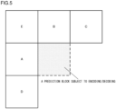
- Figs. 5 , 6 , 7 , and 8 illustrate: a deprivation of a spatial merge candidate; and a prediction block to be referred to when deriving a spatial merge candidate and when deriving the reference index of a time merge candidate, the prediction block being in a same picture with the prediction block subject to encoding or decoding and being in the proximity of the prediction block subject to encoding or decoding.
- Fig. 9 illustrates a prediction block to be referred to when deriving the reference index of a time merge candidate, the prediction block being in an encoded or decoded picture different in time from the prediction block subject to encoding or decoding and being at a position identical to or in the proximity of the prediction block subject to encoding or decoding.
- a prediction block A adjacent to the left edge of the prediction block subject to encoding or decoding, a prediction block B adjacent to the upper edge thereof, a prediction block C adjacent to the upper right vertex thereof, a prediction block D adjacent to the lower left vertex thereof, and a prediction block E adjacent to the upper left vertex thereof are defined as a prediction block in the spatial proximity.
- a prediction block A10 at the lowest position among the plurality of prediction blocks adjacent to the left edge is defined as a prediction block A adjacent to the left edge according to the present embodiment.
- a prediction block B10 at the right most position among the plurality of prediction blocks adjacent to the upper edge is defined as a prediction block B1 adjacent to the upper edge according to the present embodiment.
- the prediction block A is defined as a prediction block A if the prediction block A is adjacent to the left edge of the prediction block subject to encoding or decoding, is defined as a prediction block D in case of being adjacent to the lower left vertex of the prediction block subject to encoding or decoding, and is defined as a prediction block E in case of being adjacent to the upper left vertex of the prediction block subject to encoding or decoding.
- a prediction block A, a prediction block E, and a prediction block E are an identical prediction block.
- the prediction block G is defined as a prediction block B if the prediction block G is adjacent to the upper edge of the prediction block subject to encoding or decoding, is defined as a prediction block C if the prediction block G is adjacent to the upper right vertex of the prediction block subject to encoding or decoding, and is defined as a prediction block E if the prediction block G is adjacent to the upper left vertex of the prediction block subject to encoding or decoding.
- a prediction block B, a prediction block C, and a prediction block E are an identical prediction block.
- an encoded or decoded prediction blocks T0 and T1 in a picture different in time from a picture of the prediction block subject to encoding or decoding and at a position identical to or in the proximity of the prediction block subject to encoding or decoding are defined as a prediction block at a same position different in time.
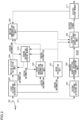
- Fig. 1 is a block diagram showing a structure of a moving picture encoding device according to an embodiment of the invention.
- the moving picture encoding device comprises a picture memory 101, a motion vector detection unit 102, a motion vector difference calculation unit 103, an inter prediction information derivation unit 104, a motion compensation prediction unit 105, an intra prediction unit 106, a prediction method determining unit 107, a residual signal generating unit 108, an orthogonal transformation/quantization unit 109, a first bitstream generating unit 110, a second bitstream generating unit 111, a multiplexing unit 112, an inverse quantization/inverse orthogonal transformation unit 113, a decoded picture signal convolution unit 114, a coding information storing memory 115, and a decoded picture memory 116.
- the motion vector detection unit 102 detects motion vectors for respective prediction block size and respective prediction modes for each prediction block by block matching or the like between a picture signal provided from the picture memory 101 and a reference picture provided from the decoded picture memory 116.
- the motion vector detection unit 102 provides the detected motion vector to the motion compensation prediction unit 105, the motion vector difference calculation unit 103, and the prediction method determining unit 107.
- the motion vector difference calculation unit 103 calculates a plurality of candidates of a motion vector predictor and stores the candidates in a motion vector predictor list, selects an optimal motion vector predictor from the plurality of candidates of a motion vector predictor registered in the motion vector predictor list, calculates a motion vector difference from the motion vector detected by the motion vector detection unit 102 and from the motion vector predictor, and provides the calculated motion vector difference to the prediction method determining unit 107. Further, the motion vector difference calculation unit 103 provides the prediction method determining unit 107 with a motion vector predictor index that specifies a motion vector predictor selected from the candidates of a motion vector predictor registered in the motion vector predictor list.
- the prediction method determining unit 107 determines a prediction mode PredMode and a partition mode PartMode that determine inter prediction (PRED_INTER) or intra prediction (PRED_INTRA) in units of optimal coding blocks from a plurality of prediction methods, by evaluating an amount of code of coding information and a residual signal, an amount of distortion between a prediction picture signal and a picture signal or the like for respective prediction methods.
- PRED_INTER inter prediction
- the prediction method determining unit 107 determines whether or not a mode is a merge mode in units of prediction blocks.
- the bitstream provided to the separation unit 201 is separated in accordance with a prescribed syntax rule.
- the separated first bitstream is provided to the first bitstream decoding unit 202, and the second bitstream is provided to the second bitstream decoding unit 203.
- the flag predFlagLO indicating whether or not to use L0 prediction is 1
- the flag predFlagL1 indicating whether or not to use L1 prediction is 0.
- the flag predFlagLO indicating whether or not to use L0 prediction is 0, and the flag predFlagL1 indicating whether or not to use L1 prediction is 1.
- the motion compensation prediction unit 206 generates a prediction picture signal by inter prediction (motion compensation prediction) by using inter prediction information calculated in the motion vector calculation unit 204 or in the inter prediction information derivation unit 205 from a reference picture stored in the decoded picture memory 211, and provides the prediction picture signal to the decoded picture signal convolution unit 209.
- inter prediction motion compensation prediction
- two motion compensation prediction picture signals of L0 prediction and L1 prediction are multiplied by a weighting coefficient adaptively, and convolution is performed so as to generate an ultimate prediction picture signal.
- the intra prediction unit 207 performs intra prediction when the prediction mode PredMode of a prediction block to be decoded is intra prediction (PRED_INTRA) .
- the coding information decoded in the first bitstream decoding unit includes an intra prediction mode. Based on the intra prediction mode, a prediction picture signal is generated by intra prediction from the decoded picture signal stored in the decoded picture memory 211, and provided to the decoded picture signal convolution unit 209. Both flags, predFlagLO [xP] [yP] and predFlagL1[xP][yP] indicating whether or not to use L0 prediction and L1 prediction, are set to 0 and stored in the coding information storing memory 210.
- xP and yP are indexes indicating the position of an upper left pixel in a prediction block in a picture.
- the inverse quantization/inverse orthogonal transformation unit 208 inverse-orthogonally transforms and inverse quantizes the orthogonally-transformed and quantized residual signal, which is decoded in the first bitstream decoding unit 202, and obtains an inverse-orthogonally transformed and inverse quantized residual signal.
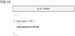
- Fig. 10 shows a first syntax structure that is described in a slice header for each slice of a bitstream generated in accordance with the present embodiment.
- the figure shows only syntax elements related to the present embodiment.
- a slice type is a B slice
- a flag collocated_from_l0_flag is established.
- the flag collocated_from_l0_flag indicates which of the reference pictures a picture colPic of a different time uses, namely, a reference picture registered in a reference list of L0 or a reference picture registered in a reference list of L1 of a picture including a prediction block subject to processing.
- the picture colPic of a different time is used when deriving a candidate of a motion vector predictor over time or when deriving a merge candidate.
- the detail on the flag collocated_from_l0_flag will be described later.
- Fig. 11 shows a syntax pattern described for each prediction block.
- the value of the prediction mode PredMode of a prediction block is inter prediction (MODE_INTER)
- merge _flag[x0][y0] that indicates whether or not a mode is a merge mode is established.
- x0 and y0 are indexes indicating the position of an upper left pixel in a prediction block in a picture of brightness signals
- merge _flag[x0][y0] is a flag indicating whether or not the mode of a prediction block positioned at (x0, y0) in the picture is a merge mode or not.
- merge_flag[x0][y0] is 1, which indicates that the mode is a merge mode
- a syntax element merge_idx[x0][y0] of an index of a merge list which is a list of merge candidates to be referred to, is established.
- x0 and y0 are indexes indicating the position of an upper left pixel in a prediction block in a picture
- merge_flag[x0][y0] is a merge index of a prediction block positioned at (x0, y0) in the picture.
- Fig. 12 shows an example of an entropy code of a syntax element merge_idx[x0][y0] of a merge index.
- the number of candidates of merge is set to 5.
- the code of syntax element merge_idx[x0][y0] of a merge index is '0', '10', '110', '1110', and '1111', respectively.
- merge_flag[x0][y0] indicates that the mode is not a merge mode
- the slice type is a B slice
- L0 prediction Pred_L0
- L1 prediction Pred_L1
- Pred_BI bi-prediction
- syntax elements of reference index ref_idx_l0[x0][y0] and ref_idx_l1[x0][y0] for specifying a reference picture and syntax elements mvd_l0[x0] [y0] [j] and mvd_l1[x0] [y0] [j] of a motion vector difference, which is a difference between a motion vector of a prediction block derived by detection of a motion vector and a motion vector predictor, are established.
- x0 and y0 are indexes indicating the position of an upper left pixel in a prediction block in a picture.
- ref_idx_l0[x0] [y0] and mvd_l0[x0] [y0] [j] are a reference index and a motion vector difference of L0 of a prediction block positioned at (x0, y0) in the picture, respectively.
- ref_idx_l1[x0][y0],mvd_l1[x0][y0] [j] are a reference index and a motion vector difference of L1 of a prediction block positioned at (x0, y0) in the picture, respectively.
- j indicates components of motion vector difference.
- a value 0 for j represents x component
- a value 1 for j represents y component.
- syntax elements mvp_idx_l0[x0][y0] and mvp_idx_l1[x0] [y0] of index of a motion vector predictor list which is a list of candidates of motion vector predictor to be referred to, is established.
- x0 and y0 are indexes indicating the position of an upper left pixel in a prediction block in a picture.
- mvp_idx_l0[x0] [y0] and mvp_idx_l1[x0] [y0] are motion vector predictor index of L0 and L1 of a prediction block positioned at (x0, y0) in the picture.
- the value of the number of candidates is set to 2.
- a method for deriving inter prediction information according to the embodiment is performed in the inter prediction information derivation unit 104 of the moving picture encoding device of Fig. 1 and in the inter prediction information derivation unit 205 of the moving picture decoding device of Fig. 2 .
- a merge candidate is derived not only from the five prediction blocks (i.e., a prediction block A adjacent to the left, a prediction block B adjacent to the top, a prediction block C adjacent to the upper right, a prediction block D adjacent to the lower left, and a prediction block E adjacent to the upper left) explained while referring to Figs. 5 , 6 , 7 , and 8 , but also from a prediction block of a prediction block Col (T0 or T1) at an identical position or in a proximity and different in time, which has been explained while referring to Fig. 9 .
- the inter prediction information derivation unit 205 of the moving picture decoding device selects a prediction block from the merge candidate list in accordance with a merge index decoded in the first bitstream decoding unit 202 and provided, and performs motion compensation prediction by using inter prediction information (e.g., a prediction mode, a reference index, a motion vector, or the like) of the selected merge candidate.
- inter prediction information e.g., a prediction mode, a reference index, a motion vector, or the like
- merge candidate derivation and merge candidate list construction process in merge candidate derivation and in merge candidate list construction process in the construction unit 120 of merge candidate list of the moving picture encoding device and the construction unit 220 of merge candidate list of the moving picture decoding device, it is assumed that merge candidate derivation and merge candidate list construction process of a prediction block subject to processing are performed without referring to a prediction block included in a coding block identical to a coding block including a prediction block subject to processing.
- Figs. 15F, 15F, and 15G show prediction blocks in the proximity in case that a partition mode (PartMode) is N by 2N partition (PART_Nx2N), nL by 2N partition (PART_nLx2N), or nR by 2N partition (PART_nRx2N), where a coding block subject to processing is partitioned into two prediction blocks arranged horizontally.
- the prediction block A1 in the proximity of a prediction block subject to processing, of which PartIdx is 1, is a prediction block of which PartIdx is 0.
- a time merge candidate is derived from a picture of a different time and the time merge candidate is outputted.
- a merge candidate list is generated, and spatial merge candidates A, B, C, D, and E, and a time merge candidate Col are added to the merge candidate list mergeCandList, by which, the merge candidate list mergeCandList is established, and the merge candidate list mergeCandList is outputted (step S204).
- a merge candidate list is generated, in case that motion vectors of reference indexes of an identical merge candidate have a same value in the merge candidate list mergeCandList, the merge candidate is omitted except for a merge candidate that is earliest in the order, and the merge candidate list mergeCandList is outputted (step S205).
- a merge candidate list is supplemented so that the number of merge candidates registered in the merge candidate list mergeCandList, and the merge candidate list mergeCandList is outputted (step S206).
- the number of merge candidates is set to 5.
- Fig. 18 by assigning A as a parameter N, coding information of a prediction block A adjacent to the left edge of a prediction block subject to encoding or decoding is checked and a merge candidate A is derived, by assigning B as a parameter N, coding information of a prediction block B adjacent to the upper edge is checked and a merge candidate B is derived, by assigning C as a parameter N, coding information of a prediction block C adjacent to the upper right is checked and a merge candidate C is derived, by assigning D as a parameter N, coding information of a prediction block D adjacent to the lower left is checked and a merge candidate D is derived, and by assigning E as a parameter N, coding information of a prediction block E adjacent to the upper left is checked and a merge candidate E is derived(step S1101 - step S1114).
- a flag of a merge candidate E availableFlagE is set to 0 (step S1107), both values of motion vectors mvL0E and mvL1E of merge candidate E are set to (0,0) (step S1108), both values of flags predFlagL0E and predFlagL1E of merge candidate E are set to 0 (step S1109), and this spatial merge candidate derivation process is completed.
- up to four spatial merge candidate are derived from prediction blocks in the proximity. Therefore, in case that four spatial merge candidates have been derived already, it is not required to perform the derivation process of spatial merge candidates any more.
- step S1103 in case that the parameter N is not E, or in case that values of a flags availableFlagA, availableFlagB, availableFlagC, and availableFlagD are added and the total thereof is not 4 (NO in S1102), the method proceeds to step S1103.
- the prediction block N in the proximity is included in a coding block identical to a coding block including a prediction block subject to derivation (YES in step S1103)
- the value of a flag availableFlagN of a merge candidate N is set to 0 (step S1107)
- both values of motion vectors mvLON and mvL1N of the merge candidate N are set to (0,0) (step S1108)
- both values of flags predFlagLON and predFlagL1N of the merge candidate N are set to 0 (step S1109).
- the value of a flag availableFlagN of merge candidate N is set to 0 (step S1107), by not referring to coding information of the prediction block N in the proximity and by setting the value of flag availableFlagN of the merge candidate N to 0, so as not to using as a spatial merge candidate, merge candidate derivation and merge candidate list construction process for respective prediction blocks in a same coding block can be processed in parallel.
- the case of prediction block B adjacent to the upper edge of a prediction block subject to derivation where a partition mode is 2N by N partition (PART_2NxN), 2N by nU partition (PART_2NxnU), or 2N by nD partition (PART _2NxnD) and where that PartIdx of a prediction block subject to processing is 1, corresponds to the case where the prediction block N in the proximity is included in a coding block identical to a coding block including a prediction block subject to derivation.
- the prediction block B adjacent to the upper edge of a prediction block subject to derivation is a prediction block which is included in a coding block identical to a coding block including a prediction block subject to derivation and of which the PartIdx is 0. Therefore, by not referring to coding information of the prediction block B in the proximity and by setting the value of flag availableFlagB of the merge candidate B to 0 so as not to using as a spatial merge candidate, merge candidate derivation and merge candidate list construction process for respective prediction blocks in a same coding block can be processed in parallel.
- a partition mode is N by 2N partition (PART_Nx2N), nL by 2N partition (PART_nLx2N), or nR by 2N partition (PART_nRx2N) and where PartIdx of a prediction block subject to processing is 1, also corresponds to the case where the prediction block N in the proximity is included in a coding block identical to a coding block including a prediction block subject to derivation.
- the prediction block A adjacent to the left edge of a prediction block subject to derivation is a prediction block which is included in a coding block identical to a coding block including a prediction block subject to derivation and of which the PartIdx is 0. Therefore, by not referring to coding information of the prediction block A in the proximity and by setting the value of flag availableFlagA of the merge candidate A to 0 so as not to using as a spatial merge candidate, merge candidate derivation and merge candidate list construction process for respective prediction blocks in a same coding block can be processed in parallel.
- PartMode is N by N partition (PART_NxN)
- PartIdx of a prediction block subject to processing is 1, 2, or 3
- the prediction block N in the proximity is sometimes included in a coding block identical to a coding block including a prediction block subject to derivation.
- the prediction block N in the proximity is not included in a coding block identical to a coding block including a prediction block subject to derivation (YES in step S1103)
- the prediction block N in the proximity of a prediction block subject to encoding or decoding is specified, and in case that respective prediction blocks N are available, coding information of a prediction block N is derived from the coding information storing memory 115 or from the coding information storing memory 210 (step S1104).
- step S1106 If the prediction block N in the proximity cannot be used (NO in step S1105), or the prediction mode PredMode of the prediction block N is intra prediction (MODE_INTRA) (YES in step S1106), the value of a flag availableFlagN of a merge candidate N is set to 0 (step S1107), both values of motion vectors mvLON and mvL1N of the merge candidate N are set to (0,0) (step S1108), and both values of flags predFlagLON and predFlagL1N of the merge candidate N are set to 0 (step S1109).
- the case where a prediction block N in the proximity cannot be used corresponds, for example, to a case where the prediction block N in the proximity is positioned outside of a slice subject to encoding or decoding, a case where encoding or decoding process has not been completed because the block N is late in the processing order of encoding or decoding process, etc.
- the prediction block N in the proximity is outside of a coding block identical to a coding block including a prediction block subject to derivation (YES in step S1104), the prediction block N in the proximity is available (YES in step S1105), and in case that the prediction mode PredMode of the prediction block N is not an intra prediction (MODE_INTRA) (YES in step S1106), the inter prediction information of the prediction block N is used as the inter prediction information of the merge candidate N.
- the prediction mode PredMode of the prediction block N is not an intra prediction (MODE_INTRA)
- the value of a flag availableFlagN of the merge candidate N is set to 1 (step S1110), the motion vectors mvLON and mvL1N of the merge candidate N are set to a value identical to that of the motion vectors mvL0N[xN] [yN] and mvL1N[xN] [yN] of respective prediction block N (step S1111), the reference indexes refIdxL0N and refIdxL1N of the merge candidate N are set to a value identical to that of the reference indexes refIdxL0[xN] [yN] and refIdxL1[xN] [yN] of respective prediction block N (step S1112), and flags predFlagLON and predFlagL1N of a merge candidate N are set to flags predFlagL0 [xN] [yN] and predFlagL1[xN] [yN] of respective prediction block N (step S1113).
- reference indexes of a time merge candidate is derived by using a reference index of a spatial merge candidate, that is, a reference index used in a prediction block in the proximity of a prediction block subject to encoding or decoding. This is because, in case that a time merge candidate is selected, a reference index of a prediction block subject to encoding or decoding has a high correlation with the reference index of a prediction block in the proximity of a prediction block subject to encoding or decoding, which will be a spatial merge candidate.
- a reference index of a prediction block A adjacent to the left edge of the prediction block subject to derivation, or a prediction block B adjacent to the upper edge thereof is used, except for a sixth exemplary embodiment and a seventh exemplary embodiment, which will be described later.
- the prediction blocks A and B adjacent to the edge of the prediction block subject to encoding or decoding, among the prediction blocks A,B,C,D, and E in the proximity, which are also a spatial merge candidates have a higher correlation than the prediction blocks C,D, and E adjacent only to a vertex.
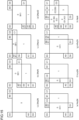
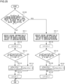
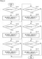
- PartMode is N by 2N partition (PART_Nx2N), nL by 2N partition (PART_nLx2N), or nR by 2N partition (PART_nRx2N), where coding block subject to processing is partitioned into two prediction blocks arranged horizontally, as shown in Fig. 20E, 20F, and 20G , a prediction block adjacent to the upper edge of a prediction block subject to derivation is referred to, and respective reference indexes of LX of time merge candidates are set to values of reference indexes of LX of prediction blocks adjacent to the upper edge of respective prediction blocks subject to derivation.
- a reference index of LX of a time merge candidate is set to a default value 0.
- the reason why the default value of a reference index of LX of a time merge candidate is set to 0 in case that prediction blocks A and B in the proximity do not perform LX prediction is that a reference picture corresponding to the reference index value 0 has the highest possibility to be selected in inter prediction.
- the scope of the present invention is not limited to this example.
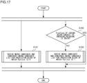
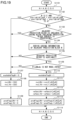
- Fig. 21 shows a flowchart illustrating procedure of derivation process of a reference index of a time merge candidate in step S202 of Fig. 18 according to the first exemplary embodiment of the present embodiment.
- PartMode is not N by 2N partition (PART_Nx2N), nL by 2N partition (PART_nLx2N), or nR by 2N partition (PART_nRx2N) (NO in step S2101), that is, in case of 2N by 2N partition (PART_2Nx2N), 2N by N partition (PART_2NxN), 2N by nU partition (PART_2NxnU), 2N by nD partition (PART_2NxnD), coding information of a prediction block A adjacent to the left is derived from the coding information storing memory 115 or 210 (step S2111).
- a prediction block B1 adjacent to the top is referred to, and a reference index of LX of a time merge candidate is set to the value of the reference index of LX of the prediction block B1. Since both prediction blocks A0 and B1 to refer to are outside of the coding block, a reference index of time merge candidate of two prediction blocks of which the partition index PartIdx are 0 and 1 respectively, can be derived in parallel, respectively.
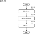
- step S2113 through step S2115 are performed for L0 and L1 respectively (step S2112 - S2116).
- LX is set to L0
- LX is set to L1.
- an inter prediction mode only includes L0 prediction (Pred_L0) and does not include L1 prediction (Pred_L1) nor bi-prediction (Pred_BI). Therefore a process regarding L1 can be omitted.
- a reference index refIdxLXCol of LX of a time merge candidate is set to a default value 0 (step S2115).
- step S2113 through step S2115 are performed for L0 and L1 respectively (step S2112 - S2116), and the derivation process of a reference index is completed.
- a reference index refIdxLXCol of LX of a time merge candidate is set to a default value 0 (step S2121).
- a prediction block in the proximity is not referred to, and a reference index of LX of a time merge candidate is set to a default value 0. Since a prediction block in the proximity of a prediction block subject to derivation is not referred to, reference indexes of time merge candidates of four prediction blocks of which the partition index PartIdx are 0, 1, 2, and 3 respectively, can be derived in parallel, respectively.
- a prediction block A0 adjacent to the left is referred to, and a reference index of LX of a time merge candidate is set to a value of reference index of LX of the prediction block A0.
- a prediction block B1 adjacent to the top is referred to, and a reference index of LX of a time merge candidate is set to the value of the reference index of LX of the prediction block B1.
- a prediction block A2 adjacent to the left is referred to, and a reference index of LX of a time merge candidate is set to a value of reference index of LX of the prediction block A2.
- a prediction block in the proximity is not referred to, and a reference index of LX of a time merge candidate is set to a default value 0.
- a prediction block A0 adjacent to the left is referred to, and a reference index of LX of a time merge candidate is set to a value of the reference index of LX of the prediction block A0.
- a prediction block A2 adjacent to the left is referred to, and a reference index of LX of a time merge candidate is set to a value of reference index of LX of the prediction block A2.
- a prediction block in the proximity is not referred to, and a reference index of LX of a time merge candidate is set to a default value 0. Since both prediction blocks A0 and A2 adjacent to the left of a prediction block subject to processing are outside of the coding block, reference indexes of time merge candidates of four prediction blocks of which the partition index PartIdx are 0, 1, 2, and 3 can be derived respectively in parallel.
- a prediction block A adjacent to the left of a coding block subject to processing is referred to, and a reference index of LX of a time merge candidate is set to a value of reference index of LX of the prediction block A. Since a prediction block A adjacent to the left of a coding block subject to processing is outside of the coding block, reference indexes of time merge candidates of four prediction blocks of which the partition index PartIdx are 0, 1, 2, and 3 can be derived respectively in parallel.
- a prediction block A0 adjacent to the left is referred to, and a reference index of LX of a time merge candidate is set to a value of the reference index of LX of the prediction block A0.
- a prediction block in the proximity is not referred to, and a reference index of LX of a time merge candidate is set to a default value 0. Since a prediction block A0 adjacent to the left of a prediction block subject to processing is outside of the coding block, reference indexes of time merge candidates of four prediction blocks of which the partition index PartIdx are 0, 1, 2, and 3 can be derived respectively in parallel.
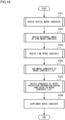
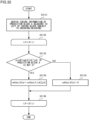
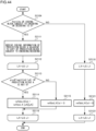
- Fig. 34 shows a flowchart illustrating procedure of time merge candidate derivation process of step S203 in Fig. 18 .
- a picture colPic of a different time is derived by a slice type slice_type and a flag collocated_from_l0_flag described above (step S3101).
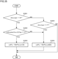
- Fig. 35 shows a flowchart illustrating procedure of derivation process of a picture colPic of a different time of step S3101 in Fig. 34 .
- a slice type slice_type is a B slice and a flag collocated_from_l0_flag described above is 0 (YES in step S3201 and YES in step S3202)
- RefPicList1[0] i.e., a picture of which the reference index of reference list L1 is 0
- step S3203 is defined as a picture colPic of a different time (step S3203).
- RefPicList0[0] i.e., a picture of which the reference index of reference list L0 is 0
- step S3205 RefPicList0[0]
- a prediction block colPU of a different time is derived, and coding information is derived (step S3102).
- Fig. 36 shows a flowchart illustrating procedure of derivation process of a prediction block colPU of a picture colPic of a different time of step S3102 in Fig. 34 .
- a prediction block positioned at a lower right (outside) of a position identical to a prediction block subject to processing is used as a prediction block colPU of a different time (step S3301).
- This prediction block corresponds to the prediction block T0 in Fig. 9 .
- coding information of the prediction block colPU of a different time is derived (step S3302).
- PredMode of the prediction block colPU of a different time cannot be used or in case that the prediction mode PredMode of the prediction block colPU of a different time is intra prediction (MODE_INTRA) (YES in step S3303 , and YES in step S3304)
- a prediction block at an upper left in the middle of a position identical to a prediction block subject to processing is used as a prediction block colPU of a different time (step S3305).
- This prediction block corresponds to the prediction block T1 in Fig. 9 .
- a motion vector predictor mvL1Col of L0 that is derived from a prediction block in another picture at a position identical to a prediction block subject to encoding or decoding, and a flag availableFlagL0Col indicating whether or not a time merge candidate Col is valid are derived (step S3103), and a motion vector predictor mvL1Col of L1 and a flag availableFlagCol indicating whether or not the time merge candidate Col is valid are derived.
- the flag availableFlagL0Col or the flag availableFlagL1Col is 1, the flag availableFlagCol indicating whether or not the time merge candidate Col is valid is set to 1.
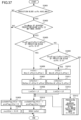
- Fig. 37 shows a flowchart illustrating procedure of derivation process of inter prediction information of time merge candidate of step S3103 and step 3104 in Fig. 34 .
- LX a list of target to derive time merge candidate
- LX prediction prediction using LX
- step S3103 which is a derivation process of L0 of time merge candidate
- step S3104 which is a derivation process of L1 of time merge candidate
- LX is set to L1.
- a prediction mode PredMode of a prediction block colPU of a different time is intra prediction (MODE_INTRA) or cannot be used, (NO in step S3401, NO in step S3402), a flag availableFlagLXCol and a flag predFlagLXCol are both set to 0 (step S3403), a motion vector mvLXCol is set to (0,0) (step S3404), the derivation process of inter prediction information of time merge candidate is completed.
- mvCol, refIdxCol, and availableFlagCol are derived in the following procedure.
- a motion vector mvCol is set to a value identical to that of MvL0[xPCol] [yPCol], which is a motion vector of L0 of the prediction block colPU (step S3410), and a reference index refIdxCol is set to a value identical to that of a reference index RefIdxL0[xPCol] [yPCol] of L0 (step S3411), and a list ListCol is set to L0 (step S3412).
- step S3501 whether or not POCs of all pictures registered in all reference lists are smaller than POC of a picture subject to encoding or decoding currently is determined (step S3501).
- POCs of all pictures registered in L0 or L1, L0 and L1 being all reference lists of prediction block colPU are smaller than POC of a picture subject to encoding or decoding currently (YES in step S3501) and LX is L0, that is, a prediction vector candidate of a motion vector of L0 of a picture subject to encoding or decode is derived (YES in step S3502), inter prediction information of L0 of the prediction block colPU is selected, and in case that LX is L1, that is, a prediction vector candidate of a motion vector of L1 of a picture subject to encoding or decode is derived (NO in step S3502), inter prediction information of L1 of the prediction block colPU is selected.
- a motion vector mvCol is set to a value identical to that of MvL0[xPCol][yPCol] (step S3504), and a reference index refIdxCol is set to a value identical to that of RefIdxL0[xPCol][yPCol] (step S3505), and a list ListCol is set to L0 (step S3506).
- a motion vector mvCol is set to a value identical to that of MvL1[xPCol][yPCol] (step S3507), and a reference index refIdxCol is set to a value identical to that of RefIdxL1[xPCol][yPCol] (step S3508), and a list ListCol is set to L1 (step S3509).
- a flag availableFlagLXCol and a flag predFlagLXCol are both set to 1 (step S3414).
- a motion vector mvCol is scaled and defined as a motion vector mvLXCol of LX of a time merge candidate (step S3415).
- An explanation will be given on procedure of scaling computation process of the motion vector, while referring to Figs. 39 and 40 .
- Fig. 39 shows a flowchart indicating procedure of scaling computation process of the motion vector of step S3105 in Fig. 34 .
- a distance td between pictures is derived (step S3601).
- POC of a reference picture referred to in a list ListCol of a prediction block colPU is previous to the picture colPic of a different time in the display order
- the distance td between pictures is a positive value
- POC of a reference picture referred to in a list ListCol of a prediction block colPU is subsequent to the picture colPic of a different time in the display order
- the distance td between pictures is a negative value.
- a distance tb between pictures is derived (step S3602).
- the distance tb between pictures is a positive value
- the distance tb between pictures is a negative value
- step S3603 distances td between pictures and tb between pictures are compared.
- the motion vector mvLXCol of LX of time merge candidate is set to a value identical to that of the motion vector mvCol (step S3604), the scaling computation process is completed.
- mvLXCol mvCol
- step S3603 scaling computation process is performed by multiplying mvCol by tb or td in accordance with the following equation (step S3605), and a scaled motion vector mvLXCol of LX of time merge candidate is obtained.
- mvLXCol tb or td * mvCol
- Fig. 4 indicates an example in case that the scaling computation of step S3605 is performed with precision of integer. Processes of step S3606 - step S3608 in Fig. 40 correspond to the step S3605 of Fig. 40 .
- a distance td between pictures and a distance tb between pictures are derived (step S3601 and step S3602).
- step S3603 distances td between pictures and tb between pictures are compared.
- the motion vector mvLXCol of LX of time merge candidate is set to a value identical to that of the motion vector mvCol (step S3604) in a similar manner to the flow chart in Fig. 39 , the scaling computation process is completed.
- mvLXCol mvCol
- tx 16384 + Abs td or 2 or td
- DistScaleFactor tb * tx + 32 ⁇ 6
- mvLXCol ClipMv( Sign( DistScaleFactor * mvCol ) * ( (Abs( DistScaleFactor * mvCol ) + 127 ) >> 8 ) )
- Fig. 41 shows a flowchart indicating a processing procedure for constructing a merge candidate list.
- the method by setting priorities and registering a merge candidate from the higher priority in a merge candid list mergeCandList, the amount of code of merge index merge_idx[x0] [y0] is reduced. By putting an element of higher priority in the upper part of the merge candidate list, the amount of code is reduced.
- an index 0 of the merge candidate list is set to "0"
- an index 1 thereof is set to "10”
- an index 2 thereof is set to "110”
- an index 3 thereof is set to "1110”
- an index 4 thereof is set to "11110"
- the merge candidate list mergeCandList is configured as a list structure, and in which a merge index indicating locations in the merge candidate list, and a storage area that stores a merge candidate corresponding to the index as an element are provided.
- the number of merge index starts from 0, and a merge candidate is stored in a storage area of the merge candidate list mergeCandList.
- mergeCandList[i] a prediction block that becomes a merge candidate of a mergeindex i registered in the merge candidate list mergeCandList.
- a merge candidate A is registered at the top of the merge candidate list mergeCandList (step S4102).
- a merge candidate B is registered at the end of the merge candidate list mergeCandList (step S4104).
- a merge candidate C is registered at the end of the merge candidate list mergeCandList (step S4106).
- a merge candidate D is registered at the end of the merge candidate list mergeCandList (step S4108).
- step S4109 a merge candidate E is registered at the end of the merge candidate list mergeCandList (step S4110).
- vailableFlagCol is 1 (YES in step S4109)
- a merge candidate Col is registered at the end of the merge candidate list mergeCandList (step S4110).
- a prediction block A adjacent to the left and a prediction block B adjacent to the top often with the prediction block subject to encoding or decoding in an integrated manner.
- the merge candidates A and B are registered ahead of other merge candidates C, D, E, and Col in the candidate list, preferentially.
- a merge candidate is selected from merge candidates registered in the merge candidate list, and a merge index and inter prediction information of a merge candidate corresponding to the merge index is provided to the motion compensation prediction unit 105.
- a method similar to that of the prediction method determining unit 107 can be used. Coding information and coding distortion between an amount of code of coding information and a residual signal, and coding distortion between a prediction picture signal and a picture signal are derived for each merge candidate. A merge candidate that has the least amount of generated code and coding distortion is determined. For each merge candidate, entropy encoding is performed of syntax element merge_idx, which is coding information of a merge mode, is performed, and an amount of code of coding information is calculated. Further, for each merge candidate, an amount of code of an encoded prediction residual signal is calculated with a method similar to that of the motion compensation prediction unit 105.
- the prediction residual signal is a residual signal between a prediction picture signal, on which motion compensation is performed in accordance with inter prediction information of each merge candidate, and a picture signal, which is subject to encoding and which is provided from the picture memory 101.
- Total amount of code to which an amount of code of coding information (i.e., a merge index) and an amount of code of prediction residual signal is added is calculated and set as an evaluation value.
- a merge candidate corresponding to a provided merge index is selected from merge candidates registered in the merge candidate list, and inter prediction information of the merge candidate is provided to the motion compensation prediction unit 206, and stored in the coding information storing memory 210.
- a bitstream of moving pictures outputted from the moving picture encoding device according to the embodiments described above has a specific data format so that the data stream can be decoded in accordance with the coding method used in the embodiments.
- a moving picture decoding device corresponding to the moving picture encoding device can decode the bitstream in this specific format.
- a bitstream may be transformed into a data format appropriate to the manner of transmission on the communication path so as to be transmitted.
- a moving picture transmission device and a moving picture receiver device are provided.
- the moving picture transmission device transforms a bitstream output from the moving picture encoding device into encoded data in a data format appropriate to the manner of transmission via the communication path and transmits the encoded data to the network.
- the moving picture receiver device receives encoded data from the network, reconstructs a bitstream, and provides the bitstream to the moving picture decoding device.
- the moving picture transmission device includes a memory that buffers a bitstream output from the moving picture encoding device, a packet processing unit that packetizes the bitstream, a transmission unit that transmits the packetized bitstream via a network.
- the moving picture receiver device includes a receiving unit that receives a packetized bitstream via a network, a memory that buffers the received bitstream, and a packet processing unit that processes a packet of the encoded data so as to generate a bitstream, and provides the bitstream to the moving picture decoding device.
- the processes relating to encoding and decoding described above can be implemented as a transmission device, a storage, and/or a receiver device using hardware.
- the process can also be implemented by firmware stored in a read only memory (ROM), a flash memory, or the like, or by software of computers or the like.
- the firmware program or the software program can be stored in a recording medium readable by a computer or the like and provided, can be provided from a server via a wired or wireless network, or can be provided by data broadcasting as terrestrial broadcasting or satellite digital broadcasting.
- the present invention is applicable to a moving picture encoding technology utilizing motion compensation prediction.
Landscapes
- Engineering & Computer Science (AREA)
- Multimedia (AREA)
- Signal Processing (AREA)
- Compression Or Coding Systems Of Tv Signals (AREA)
- Compression, Expansion, Code Conversion, And Decoders (AREA)
Applications Claiming Priority (9)
| Application Number | Priority Date | Filing Date | Title |
|---|---|---|---|
| JP2011276457 | 2011-12-16 | ||
| JP2011276456 | 2011-12-16 | ||
| JP2011289287 | 2011-12-28 | ||
| JP2011289288 | 2011-12-28 | ||
| EP20169995.6A EP3703371B1 (en) | 2011-12-16 | 2012-12-14 | Dynamic image encoding device, dynamic image encoding method, dynamic image encoding program, dynamic image decoding device, dynamic image decoding method, and dynamic image decoding program |
| EP12857437.3A EP2802146B1 (en) | 2011-12-16 | 2012-12-14 | Dynamic image decoding device, dynamic image decoding method, and dynamic image decoding program |
| PCT/JP2012/008016 WO2013088738A1 (ja) | 2011-12-16 | 2012-12-14 | 動画像符号化装置、動画像符号化方法及び動画像符号化プログラム、並びに動画像復号装置、動画像復号方法及び動画像復号プログラム |
| EP19217766.5A EP3654651B1 (en) | 2011-12-16 | 2012-12-14 | Dynamic image encoding device, dynamic image encoding method, dynamic image encoding program, dynamic image decoding device, dynamic image decoding method, and dynamic image decoding program |
| EP19156821.1A EP3503554B1 (en) | 2011-12-16 | 2012-12-14 | Dynamic image encoding device, dynamic image encoding method, dynamic image encoding program |
Related Parent Applications (5)
| Application Number | Title | Priority Date | Filing Date |
|---|---|---|---|
| EP20169995.6A Division-Into EP3703371B1 (en) | 2011-12-16 | 2012-12-14 | Dynamic image encoding device, dynamic image encoding method, dynamic image encoding program, dynamic image decoding device, dynamic image decoding method, and dynamic image decoding program |
| EP20169995.6A Division EP3703371B1 (en) | 2011-12-16 | 2012-12-14 | Dynamic image encoding device, dynamic image encoding method, dynamic image encoding program, dynamic image decoding device, dynamic image decoding method, and dynamic image decoding program |
| EP19217766.5A Division EP3654651B1 (en) | 2011-12-16 | 2012-12-14 | Dynamic image encoding device, dynamic image encoding method, dynamic image encoding program, dynamic image decoding device, dynamic image decoding method, and dynamic image decoding program |
| EP19156821.1A Division EP3503554B1 (en) | 2011-12-16 | 2012-12-14 | Dynamic image encoding device, dynamic image encoding method, dynamic image encoding program |
| EP12857437.3A Division EP2802146B1 (en) | 2011-12-16 | 2012-12-14 | Dynamic image decoding device, dynamic image decoding method, and dynamic image decoding program |
Publications (3)
| Publication Number | Publication Date |
|---|---|
| EP3907997A1 EP3907997A1 (en) | 2021-11-10 |
| EP3907997C0 EP3907997C0 (en) | 2025-04-09 |
| EP3907997B1 true EP3907997B1 (en) | 2025-04-09 |
Family
ID=49479186
Family Applications (6)
| Application Number | Title | Priority Date | Filing Date |
|---|---|---|---|
| EP21181798.6A Active EP3907997B1 (en) | 2011-12-16 | 2012-12-14 | Dynamic image encoding device, dynamic image encoding method, dynamic image encoding program, dynamic image decoding device, dynamic image decoding method, and dynamic image decoding program |
| EP20169994.9A Active EP3703370B1 (en) | 2011-12-16 | 2012-12-14 | Dynamic image encoding device, dynamic image encoding method, dynamic image encoding program, dynamic image decoding device, dynamic image decoding method, and dynamic image decoding program |
| EP12857437.3A Active EP2802146B1 (en) | 2011-12-16 | 2012-12-14 | Dynamic image decoding device, dynamic image decoding method, and dynamic image decoding program |
| EP20169995.6A Active EP3703371B1 (en) | 2011-12-16 | 2012-12-14 | Dynamic image encoding device, dynamic image encoding method, dynamic image encoding program, dynamic image decoding device, dynamic image decoding method, and dynamic image decoding program |
| EP19156821.1A Active EP3503554B1 (en) | 2011-12-16 | 2012-12-14 | Dynamic image encoding device, dynamic image encoding method, dynamic image encoding program |
| EP19217766.5A Active EP3654651B1 (en) | 2011-12-16 | 2012-12-14 | Dynamic image encoding device, dynamic image encoding method, dynamic image encoding program, dynamic image decoding device, dynamic image decoding method, and dynamic image decoding program |
Family Applications After (5)
| Application Number | Title | Priority Date | Filing Date |
|---|---|---|---|
| EP20169994.9A Active EP3703370B1 (en) | 2011-12-16 | 2012-12-14 | Dynamic image encoding device, dynamic image encoding method, dynamic image encoding program, dynamic image decoding device, dynamic image decoding method, and dynamic image decoding program |
| EP12857437.3A Active EP2802146B1 (en) | 2011-12-16 | 2012-12-14 | Dynamic image decoding device, dynamic image decoding method, and dynamic image decoding program |
| EP20169995.6A Active EP3703371B1 (en) | 2011-12-16 | 2012-12-14 | Dynamic image encoding device, dynamic image encoding method, dynamic image encoding program, dynamic image decoding device, dynamic image decoding method, and dynamic image decoding program |
| EP19156821.1A Active EP3503554B1 (en) | 2011-12-16 | 2012-12-14 | Dynamic image encoding device, dynamic image encoding method, dynamic image encoding program |
| EP19217766.5A Active EP3654651B1 (en) | 2011-12-16 | 2012-12-14 | Dynamic image encoding device, dynamic image encoding method, dynamic image encoding program, dynamic image decoding device, dynamic image decoding method, and dynamic image decoding program |
Country Status (12)
| Country | Link |
|---|---|
| US (5) | US9674545B2 (pl) |
| EP (6) | EP3907997B1 (pl) |
| BR (1) | BR112014013962B1 (pl) |
| DK (5) | DK3654651T3 (pl) |
| ES (4) | ES3021869T3 (pl) |
| HR (1) | HRP20211359T1 (pl) |
| HU (6) | HUE070741T2 (pl) |
| PL (6) | PL3654651T3 (pl) |
| RU (4) | RU2598302C2 (pl) |
| SI (5) | SI3654651T1 (pl) |
| TW (5) | TWI586153B (pl) |
| WO (1) | WO2013088738A1 (pl) |
Families Citing this family (13)
| Publication number | Priority date | Publication date | Assignee | Title |
|---|---|---|---|---|
| RU2576499C2 (ru) * | 2011-09-23 | 2016-03-10 | Кт Корпорейшен | Способ получения блока-кандидата на слияние и использующее его устройство |
| ES3009551T3 (en) * | 2014-10-31 | 2025-03-27 | Samsung Electronics Co Ltd | Video decoding method using high-precision motion vector encoding |
| US10477233B2 (en) * | 2015-09-30 | 2019-11-12 | Apple Inc. | Predictor candidates for motion estimation search systems and methods |
| CN116708783A (zh) * | 2016-07-12 | 2023-09-05 | 韩国电子通信研究院 | 图像编码/解码方法以及用于该方法的记录介质 |
| WO2018026222A1 (ko) * | 2016-08-03 | 2018-02-08 | 주식회사 케이티 | 비디오 신호 처리 방법 및 장치 |
| US11470346B2 (en) * | 2018-05-09 | 2022-10-11 | Sharp Kabushiki Kaisha | Systems and methods for performing motion vector prediction using a derived set of motion vectors |
| US10855986B2 (en) * | 2018-05-29 | 2020-12-01 | Qualcomm Incorporated | Bandwidth compression for neural network systems |
| MX2022003940A (es) * | 2019-10-03 | 2022-04-25 | Huawei Tech Co Ltd | Proceso de codificacion para modo de particion geometrica. |
| CN111263151B (zh) * | 2020-04-26 | 2020-08-25 | 腾讯科技(深圳)有限公司 | 视频编码方法、装置、电子设备和计算机可读存储介质 |
| CN115567714B (zh) * | 2020-12-02 | 2025-03-21 | 浙江大华技术股份有限公司 | 帧间预测方法、视频编码方法及相关装置 |
| US11949863B2 (en) * | 2021-08-02 | 2024-04-02 | Tencent America LLC | Geometric partition mode with intra block copy |
| US20240430454A1 (en) * | 2021-08-18 | 2024-12-26 | Lg Electronics Inc. | Method and apparatus for feature encoding/decoding on basis of correlation between channels, and recording medium having bitstream stored therein |
| EP4409882A4 (en) * | 2021-09-29 | 2025-08-20 | Alibaba Damo Hangzhou Tech Co Ltd | ENHANCED TEMPORAL MERGE CANDIDATES IN MERGE CANDIDATE LISTS IN VIDEO CODING |
Family Cites Families (21)
| Publication number | Priority date | Publication date | Assignee | Title |
|---|---|---|---|---|
| KR100506864B1 (ko) * | 2002-10-04 | 2005-08-05 | 엘지전자 주식회사 | 모션벡터 결정방법 |
| JP3968712B2 (ja) * | 2003-04-28 | 2007-08-29 | ソニー株式会社 | 動き予測補償装置及びその方法 |
| US7145950B2 (en) * | 2003-07-14 | 2006-12-05 | Primax Electronics Ltd. | Method of motion vector determination in digital video compression |
| JP4591657B2 (ja) * | 2003-12-22 | 2010-12-01 | キヤノン株式会社 | 動画像符号化装置及びその制御方法、プログラム |
| KR101349599B1 (ko) * | 2005-09-26 | 2014-01-10 | 미쓰비시덴키 가부시키가이샤 | 동화상 복호 장치 |
| CN100525446C (zh) * | 2005-12-26 | 2009-08-05 | 凌阳科技股份有限公司 | 可纵向译码输出的区块译码方法及装置 |
| JP4790446B2 (ja) * | 2006-03-01 | 2011-10-12 | 三菱電機株式会社 | 動画像復号装置及び動画像符号化装置 |
| WO2008053746A1 (fr) * | 2006-10-30 | 2008-05-08 | Nippon Telegraph And Telephone Corporation | Procédé de génération d'informations de référence prédictives, procédé de codage et de décodage d'image dynamiques, leur dispositif, leur programme et support de stockage contenant le programme |
| US8345968B2 (en) * | 2007-06-28 | 2013-01-01 | Mitsubishi Electric Corporation | Image encoding device, image decoding device, image encoding method and image decoding method |
| JP2009164880A (ja) * | 2008-01-07 | 2009-07-23 | Mitsubishi Electric Corp | トランスコーダ及び受信機 |
| JP5406465B2 (ja) * | 2008-04-24 | 2014-02-05 | 株式会社Nttドコモ | 画像予測符号化装置、画像予測符号化方法、画像予測符号化プログラム、画像予測復号装置、画像予測復号方法及び画像予測復号プログラム |
| JP5401071B2 (ja) * | 2008-10-09 | 2014-01-29 | 株式会社Nttドコモ | 動画像符号化装置、動画像復号装置、動画像符号化方法、動画像復号方法、動画像符号化プログラム、動画像復号プログラム、動画像処理システムおよび動画像処理方法 |
| EP2237557A1 (en) * | 2009-04-03 | 2010-10-06 | Panasonic Corporation | Coding for filter coefficients |
| KR101456498B1 (ko) * | 2009-08-14 | 2014-10-31 | 삼성전자주식회사 | 계층적 부호화 단위의 스캔 순서를 고려한 비디오 부호화 방법 및 장치, 비디오 복호화 방법 및 장치 |
| US8971400B2 (en) * | 2010-04-14 | 2015-03-03 | Mediatek Inc. | Method for performing hybrid multihypothesis prediction during video coding of a coding unit, and associated apparatus |
| US10171813B2 (en) | 2011-02-24 | 2019-01-01 | Qualcomm Incorporated | Hierarchy of motion prediction video blocks |
| US9866859B2 (en) * | 2011-06-14 | 2018-01-09 | Texas Instruments Incorporated | Inter-prediction candidate index coding independent of inter-prediction candidate list construction in video coding |
| US9313494B2 (en) * | 2011-06-20 | 2016-04-12 | Qualcomm Incorporated | Parallelization friendly merge candidates for video coding |
| KR20130050406A (ko) | 2011-11-07 | 2013-05-16 | 오수미 | 머지 모드에서의 움직임 정보 생성 방법 |
| KR20130050407A (ko) | 2011-11-07 | 2013-05-16 | 오수미 | 인터 모드에서의 움직임 정보 생성 방법 |
| JP5561348B2 (ja) | 2011-12-16 | 2014-07-30 | 株式会社Jvcケンウッド | 動画像復号装置、動画像復号方法、及び動画像復号プログラム、並びに、受信装置、受信方法、及び受信プログラム |
-
2012
- 2012-12-14 HU HUE21181798A patent/HUE070741T2/hu unknown
- 2012-12-14 PL PL19217766T patent/PL3654651T3/pl unknown
- 2012-12-14 PL PL12857437T patent/PL2802146T3/pl unknown
- 2012-12-14 DK DK19217766.5T patent/DK3654651T3/da active
- 2012-12-14 EP EP21181798.6A patent/EP3907997B1/en active Active
- 2012-12-14 PL PL19156821T patent/PL3503554T3/pl unknown
- 2012-12-14 EP EP20169994.9A patent/EP3703370B1/en active Active
- 2012-12-14 EP EP12857437.3A patent/EP2802146B1/en active Active
- 2012-12-14 ES ES21181798T patent/ES3021869T3/es active Active
- 2012-12-14 PL PL20169995T patent/PL3703371T3/pl unknown
- 2012-12-14 RU RU2014129060/08A patent/RU2598302C2/ru active
- 2012-12-14 DK DK20169995.6T patent/DK3703371T3/da active
- 2012-12-14 PL PL21181798.6T patent/PL3907997T3/pl unknown
- 2012-12-14 ES ES19217766T patent/ES2877369T3/es active Active
- 2012-12-14 DK DK20169994.9T patent/DK3703370T3/da active
- 2012-12-14 HU HUE19156821A patent/HUE047995T2/hu unknown
- 2012-12-14 SI SI201231928T patent/SI3654651T1/sl unknown
- 2012-12-14 SI SI201231946T patent/SI3703371T1/sl unknown
- 2012-12-14 ES ES20169995T patent/ES2888805T3/es active Active
- 2012-12-14 RU RU2016132152A patent/RU2636688C1/ru active
- 2012-12-14 EP EP20169995.6A patent/EP3703371B1/en active Active
- 2012-12-14 SI SI201231947T patent/SI3703370T1/sl unknown
- 2012-12-14 BR BR112014013962A patent/BR112014013962B1/pt active IP Right Grant
- 2012-12-14 EP EP19156821.1A patent/EP3503554B1/en active Active
- 2012-12-14 SI SI201231576T patent/SI2802146T1/sl unknown
- 2012-12-14 HU HUE20169994A patent/HUE055993T2/hu unknown
- 2012-12-14 EP EP19217766.5A patent/EP3654651B1/en active Active
- 2012-12-14 PL PL20169994T patent/PL3703370T3/pl unknown
- 2012-12-14 DK DK12857437.3T patent/DK2802146T3/en active
- 2012-12-14 HU HUE20169995A patent/HUE055991T2/hu unknown
- 2012-12-14 HU HUE19217766A patent/HUE053940T2/hu unknown
- 2012-12-14 DK DK19156821.1T patent/DK3503554T3/da active
- 2012-12-14 SI SI201231755T patent/SI3503554T1/sl unknown
- 2012-12-14 WO PCT/JP2012/008016 patent/WO2013088738A1/ja not_active Ceased
- 2012-12-14 HU HUE12857437A patent/HUE043876T2/hu unknown
- 2012-12-14 ES ES20169994T patent/ES2886342T3/es active Active
- 2012-12-17 TW TW106102654A patent/TWI586153B/zh active
- 2012-12-17 TW TW106102656A patent/TWI593277B/zh active
- 2012-12-17 TW TW105127072A patent/TWI578766B/zh active
- 2012-12-17 TW TW106102655A patent/TWI607649B/zh active
- 2012-12-17 TW TW101147838A patent/TWI559746B/zh active
-
2014
- 2014-06-06 US US14/298,635 patent/US9674545B2/en active Active
-
2016
- 2016-06-29 US US15/196,872 patent/US9743104B2/en active Active
-
2017
- 2017-05-01 US US15/583,601 patent/US9906810B2/en active Active
- 2017-05-01 US US15/583,577 patent/US9906809B2/en active Active
- 2017-05-01 US US15/583,616 patent/US9906811B2/en active Active
-
2018
- 2018-03-30 RU RU2018111499A patent/RU2678507C9/ru active
- 2018-03-30 RU RU2018111498A patent/RU2679552C1/ru active
-
2021
- 2021-08-26 HR HRP20211359TT patent/HRP20211359T1/hr unknown
Also Published As
Similar Documents
| Publication | Publication Date | Title |
|---|---|---|
| EP3907997B1 (en) | Dynamic image encoding device, dynamic image encoding method, dynamic image encoding program, dynamic image decoding device, dynamic image decoding method, and dynamic image decoding program | |
| JP6644270B2 (ja) | 動画像符号化装置、動画像符号化方法、動画像符号化プログラム、送信装置、送信方法及び送信プログラム | |
| JP5942782B2 (ja) | 動画像復号装置、動画像復号方法、動画像復号プログラム、受信装置、受信方法及び受信プログラム | |
| JP6229806B2 (ja) | 動画像復号装置、動画像復号方法、動画像復号プログラム、受信装置、受信方法及び受信プログラム | |
| RU2666275C1 (ru) | Устройство и способ кодирования движущегося изображения, долговременный считываемый компьютером носитель записи, на который записана программа кодирования изображения |
Legal Events
| Date | Code | Title | Description |
|---|---|---|---|
| PUAI | Public reference made under article 153(3) epc to a published international application that has entered the european phase |
Free format text: ORIGINAL CODE: 0009012 |
|
| STAA | Information on the status of an ep patent application or granted ep patent |
Free format text: STATUS: REQUEST FOR EXAMINATION WAS MADE |
|
| 17P | Request for examination filed |
Effective date: 20210625 |
|
| AC | Divisional application: reference to earlier application |
Ref document number: 2802146 Country of ref document: EP Kind code of ref document: P Ref document number: 3503554 Country of ref document: EP Kind code of ref document: P Ref document number: 3654651 Country of ref document: EP Kind code of ref document: P Ref document number: 3703371 Country of ref document: EP Kind code of ref document: P |
|
| AK | Designated contracting states |
Kind code of ref document: A1 Designated state(s): AL AT BE BG CH CY CZ DE DK EE ES FI FR GB GR HR HU IE IS IT LI LT LU LV MC MK MT NL NO PL PT RO RS SE SI SK SM TR |
|
| B565 | Issuance of search results under rule 164(2) epc |
Effective date: 20210806 |
|
| STAA | Information on the status of an ep patent application or granted ep patent |
Free format text: STATUS: EXAMINATION IS IN PROGRESS |
|
| 17Q | First examination report despatched |
Effective date: 20230102 |
|
| GRAP | Despatch of communication of intention to grant a patent |
Free format text: ORIGINAL CODE: EPIDOSNIGR1 |
|
| STAA | Information on the status of an ep patent application or granted ep patent |
Free format text: STATUS: GRANT OF PATENT IS INTENDED |
|
| GRAS | Grant fee paid |
Free format text: ORIGINAL CODE: EPIDOSNIGR3 |
|
| INTG | Intention to grant announced |
Effective date: 20250129 |
|
| GRAA | (expected) grant |
Free format text: ORIGINAL CODE: 0009210 |
|
| STAA | Information on the status of an ep patent application or granted ep patent |
Free format text: STATUS: THE PATENT HAS BEEN GRANTED |
|
| AC | Divisional application: reference to earlier application |
Ref document number: 2802146 Country of ref document: EP Kind code of ref document: P Ref document number: 3503554 Country of ref document: EP Kind code of ref document: P Ref document number: 3654651 Country of ref document: EP Kind code of ref document: P Ref document number: 3703371 Country of ref document: EP Kind code of ref document: P |
|
| AK | Designated contracting states |
Kind code of ref document: B1 Designated state(s): AL AT BE BG CH CY CZ DE DK EE ES FI FR GB GR HR HU IE IS IT LI LT LU LV MC MK MT NL NO PL PT RO RS SE SI SK SM TR |
|
| REG | Reference to a national code |
Ref country code: GB Ref legal event code: FG4D |
|
| REG | Reference to a national code |
Ref country code: CH Ref legal event code: EP |
|
| REG | Reference to a national code |
Ref country code: IE Ref legal event code: FG4D |
|
| U01 | Request for unitary effect filed |
Effective date: 20250409 |
|
| U07 | Unitary effect registered |
Designated state(s): AT BE BG DE DK EE FI FR IT LT LU LV MT NL PT RO SE SI Effective date: 20250415 |
|
| REG | Reference to a national code |
Ref country code: ES Ref legal event code: FG2A Ref document number: 3021869 Country of ref document: ES Kind code of ref document: T3 Effective date: 20250527 |
|
| REG | Reference to a national code |
Ref country code: SK Ref legal event code: T3 Ref document number: E 46260 Country of ref document: SK |
|
| REG | Reference to a national code |
Ref country code: HU Ref legal event code: AG4A Ref document number: E070741 Country of ref document: HU |
|
| PG25 | Lapsed in a contracting state [announced via postgrant information from national office to epo] |
Ref country code: NO Free format text: LAPSE BECAUSE OF FAILURE TO SUBMIT A TRANSLATION OF THE DESCRIPTION OR TO PAY THE FEE WITHIN THE PRESCRIBED TIME-LIMIT Effective date: 20250709 Ref country code: GR Free format text: LAPSE BECAUSE OF FAILURE TO SUBMIT A TRANSLATION OF THE DESCRIPTION OR TO PAY THE FEE WITHIN THE PRESCRIBED TIME-LIMIT Effective date: 20250710 |
|
| PG25 | Lapsed in a contracting state [announced via postgrant information from national office to epo] |
Ref country code: HR Free format text: LAPSE BECAUSE OF FAILURE TO SUBMIT A TRANSLATION OF THE DESCRIPTION OR TO PAY THE FEE WITHIN THE PRESCRIBED TIME-LIMIT Effective date: 20250409 |
|
| PG25 | Lapsed in a contracting state [announced via postgrant information from national office to epo] |
Ref country code: RS Free format text: LAPSE BECAUSE OF FAILURE TO SUBMIT A TRANSLATION OF THE DESCRIPTION OR TO PAY THE FEE WITHIN THE PRESCRIBED TIME-LIMIT Effective date: 20250709 |
|
| PG25 | Lapsed in a contracting state [announced via postgrant information from national office to epo] |
Ref country code: IS Free format text: LAPSE BECAUSE OF FAILURE TO SUBMIT A TRANSLATION OF THE DESCRIPTION OR TO PAY THE FEE WITHIN THE PRESCRIBED TIME-LIMIT Effective date: 20250809 |
|
| U20 | Renewal fee for the european patent with unitary effect paid |
Year of fee payment: 14 Effective date: 20251110 |
|
| PGFP | Annual fee paid to national office [announced via postgrant information from national office to epo] |
Ref country code: GB Payment date: 20251030 Year of fee payment: 14 |
|
| PG25 | Lapsed in a contracting state [announced via postgrant information from national office to epo] |
Ref country code: SM Free format text: LAPSE BECAUSE OF FAILURE TO SUBMIT A TRANSLATION OF THE DESCRIPTION OR TO PAY THE FEE WITHIN THE PRESCRIBED TIME-LIMIT Effective date: 20250409 |
|
| PGFP | Annual fee paid to national office [announced via postgrant information from national office to epo] |
Ref country code: HU Payment date: 20251127 Year of fee payment: 14 |
|
| PGFP | Annual fee paid to national office [announced via postgrant information from national office to epo] |
Ref country code: TR Payment date: 20251210 Year of fee payment: 14 |
|
| PGFP | Annual fee paid to national office [announced via postgrant information from national office to epo] |
Ref country code: CZ Payment date: 20251124 Year of fee payment: 14 |
|
| PGFP | Annual fee paid to national office [announced via postgrant information from national office to epo] |
Ref country code: PL Payment date: 20251028 Year of fee payment: 14 |
|
| PGFP | Annual fee paid to national office [announced via postgrant information from national office to epo] |
Ref country code: SK Payment date: 20251112 Year of fee payment: 14 |
|
| PLBE | No opposition filed within time limit |
Free format text: ORIGINAL CODE: 0009261 |
|
| STAA | Information on the status of an ep patent application or granted ep patent |
Free format text: STATUS: NO OPPOSITION FILED WITHIN TIME LIMIT |
|
| REG | Reference to a national code |
Ref country code: CH Ref legal event code: L10 Free format text: ST27 STATUS EVENT CODE: U-0-0-L10-L00 (AS PROVIDED BY THE NATIONAL OFFICE) Effective date: 20260218 |
|
| 26N | No opposition filed |
Effective date: 20260112 |
|
| PGFP | Annual fee paid to national office [announced via postgrant information from national office to epo] |
Ref country code: ES Payment date: 20260108 Year of fee payment: 14 |