EP3907884A1 - Vorrichtung und verfahren zur anpassung der leistung eines akustischen resonators auf der basis von strahl- und wellendimensionen - Google Patents
Vorrichtung und verfahren zur anpassung der leistung eines akustischen resonators auf der basis von strahl- und wellendimensionen Download PDFInfo
- Publication number
- EP3907884A1 EP3907884A1 EP19907323.0A EP19907323A EP3907884A1 EP 3907884 A1 EP3907884 A1 EP 3907884A1 EP 19907323 A EP19907323 A EP 19907323A EP 3907884 A1 EP3907884 A1 EP 3907884A1
- Authority
- EP
- European Patent Office
- Prior art keywords
- resonator
- eave
- electromechanical coupling
- gap width
- coupling coefficient
- Prior art date
- Legal status (The legal status is an assumption and is not a legal conclusion. Google has not performed a legal analysis and makes no representation as to the accuracy of the status listed.)
- Pending
Links
- 238000000034 method Methods 0.000 title claims description 11
- 230000008878 coupling Effects 0.000 claims abstract description 71
- 238000010168 coupling process Methods 0.000 claims abstract description 71
- 238000005859 coupling reaction Methods 0.000 claims abstract description 71
- 239000000758 substrate Substances 0.000 claims abstract description 16
- 238000010586 diagram Methods 0.000 description 12
- 235000019687 Lamb Nutrition 0.000 description 8
- 239000000463 material Substances 0.000 description 8
- 238000013461 design Methods 0.000 description 4
- 239000006185 dispersion Substances 0.000 description 4
- 238000003780 insertion Methods 0.000 description 4
- 230000037431 insertion Effects 0.000 description 4
- 239000011777 magnesium Substances 0.000 description 4
- 239000010936 titanium Substances 0.000 description 4
- XUIMIQQOPSSXEZ-UHFFFAOYSA-N Silicon Chemical compound [Si] XUIMIQQOPSSXEZ-UHFFFAOYSA-N 0.000 description 3
- PMHQVHHXPFUNSP-UHFFFAOYSA-M copper(1+);methylsulfanylmethane;bromide Chemical group Br[Cu].CSC PMHQVHHXPFUNSP-UHFFFAOYSA-M 0.000 description 3
- 239000010931 gold Substances 0.000 description 3
- BASFCYQUMIYNBI-UHFFFAOYSA-N platinum Chemical compound [Pt] BASFCYQUMIYNBI-UHFFFAOYSA-N 0.000 description 3
- 239000010453 quartz Substances 0.000 description 3
- 229910052710 silicon Inorganic materials 0.000 description 3
- 239000010703 silicon Substances 0.000 description 3
- VYPSYNLAJGMNEJ-UHFFFAOYSA-N silicon dioxide Inorganic materials O=[Si]=O VYPSYNLAJGMNEJ-UHFFFAOYSA-N 0.000 description 3
- FYYHWMGAXLPEAU-UHFFFAOYSA-N Magnesium Chemical compound [Mg] FYYHWMGAXLPEAU-UHFFFAOYSA-N 0.000 description 2
- RTAQQCXQSZGOHL-UHFFFAOYSA-N Titanium Chemical compound [Ti] RTAQQCXQSZGOHL-UHFFFAOYSA-N 0.000 description 2
- 229910052782 aluminium Inorganic materials 0.000 description 2
- XAGFODPZIPBFFR-UHFFFAOYSA-N aluminium Chemical compound [Al] XAGFODPZIPBFFR-UHFFFAOYSA-N 0.000 description 2
- 230000008859 change Effects 0.000 description 2
- 238000006243 chemical reaction Methods 0.000 description 2
- 239000011651 chromium Substances 0.000 description 2
- 238000004891 communication Methods 0.000 description 2
- 239000010949 copper Substances 0.000 description 2
- PCHJSUWPFVWCPO-UHFFFAOYSA-N gold Chemical compound [Au] PCHJSUWPFVWCPO-UHFFFAOYSA-N 0.000 description 2
- 229910052737 gold Inorganic materials 0.000 description 2
- 229910052451 lead zirconate titanate Inorganic materials 0.000 description 2
- 229910052749 magnesium Inorganic materials 0.000 description 2
- 230000001902 propagating effect Effects 0.000 description 2
- 229910052719 titanium Inorganic materials 0.000 description 2
- NAWXUBYGYWOOIX-SFHVURJKSA-N (2s)-2-[[4-[2-(2,4-diaminoquinazolin-6-yl)ethyl]benzoyl]amino]-4-methylidenepentanedioic acid Chemical compound C1=CC2=NC(N)=NC(N)=C2C=C1CCC1=CC=C(C(=O)N[C@@H](CC(=C)C(O)=O)C(O)=O)C=C1 NAWXUBYGYWOOIX-SFHVURJKSA-N 0.000 description 1
- WSMQKESQZFQMFW-UHFFFAOYSA-N 5-methyl-pyrazole-3-carboxylic acid Chemical compound CC1=CC(C(O)=O)=NN1 WSMQKESQZFQMFW-UHFFFAOYSA-N 0.000 description 1
- JBRZTFJDHDCESZ-UHFFFAOYSA-N AsGa Chemical compound [As]#[Ga] JBRZTFJDHDCESZ-UHFFFAOYSA-N 0.000 description 1
- 229910052684 Cerium Inorganic materials 0.000 description 1
- VYZAMTAEIAYCRO-UHFFFAOYSA-N Chromium Chemical compound [Cr] VYZAMTAEIAYCRO-UHFFFAOYSA-N 0.000 description 1
- RYGMFSIKBFXOCR-UHFFFAOYSA-N Copper Chemical compound [Cu] RYGMFSIKBFXOCR-UHFFFAOYSA-N 0.000 description 1
- 229910052692 Dysprosium Inorganic materials 0.000 description 1
- 229910052691 Erbium Inorganic materials 0.000 description 1
- 229910052693 Europium Inorganic materials 0.000 description 1
- 229910052688 Gadolinium Inorganic materials 0.000 description 1
- 229910052689 Holmium Inorganic materials 0.000 description 1
- 229910003334 KNbO3 Inorganic materials 0.000 description 1
- 229910003327 LiNbO3 Inorganic materials 0.000 description 1
- 229910012463 LiTaO3 Inorganic materials 0.000 description 1
- 229910052765 Lutetium Inorganic materials 0.000 description 1
- ZOKXTWBITQBERF-UHFFFAOYSA-N Molybdenum Chemical compound [Mo] ZOKXTWBITQBERF-UHFFFAOYSA-N 0.000 description 1
- 229910052779 Neodymium Inorganic materials 0.000 description 1
- 229910052777 Praseodymium Inorganic materials 0.000 description 1
- 229910052773 Promethium Inorganic materials 0.000 description 1
- KJTLSVCANCCWHF-UHFFFAOYSA-N Ruthenium Chemical compound [Ru] KJTLSVCANCCWHF-UHFFFAOYSA-N 0.000 description 1
- 229910052772 Samarium Inorganic materials 0.000 description 1
- 229910052771 Terbium Inorganic materials 0.000 description 1
- 229910052775 Thulium Inorganic materials 0.000 description 1
- 229910052769 Ytterbium Inorganic materials 0.000 description 1
- XLOMVQKBTHCTTD-UHFFFAOYSA-N Zinc monoxide Chemical compound [Zn]=O XLOMVQKBTHCTTD-UHFFFAOYSA-N 0.000 description 1
- 229910052785 arsenic Inorganic materials 0.000 description 1
- RQNWIZPPADIBDY-UHFFFAOYSA-N arsenic atom Chemical compound [As] RQNWIZPPADIBDY-UHFFFAOYSA-N 0.000 description 1
- 210000000746 body region Anatomy 0.000 description 1
- 239000003990 capacitor Substances 0.000 description 1
- GWXLDORMOJMVQZ-UHFFFAOYSA-N cerium Chemical compound [Ce] GWXLDORMOJMVQZ-UHFFFAOYSA-N 0.000 description 1
- 229910052804 chromium Inorganic materials 0.000 description 1
- 229910052802 copper Inorganic materials 0.000 description 1
- KBQHZAAAGSGFKK-UHFFFAOYSA-N dysprosium atom Chemical compound [Dy] KBQHZAAAGSGFKK-UHFFFAOYSA-N 0.000 description 1
- 230000000694 effects Effects 0.000 description 1
- UYAHIZSMUZPPFV-UHFFFAOYSA-N erbium Chemical compound [Er] UYAHIZSMUZPPFV-UHFFFAOYSA-N 0.000 description 1
- OGPBJKLSAFTDLK-UHFFFAOYSA-N europium atom Chemical compound [Eu] OGPBJKLSAFTDLK-UHFFFAOYSA-N 0.000 description 1
- UIWYJDYFSGRHKR-UHFFFAOYSA-N gadolinium atom Chemical compound [Gd] UIWYJDYFSGRHKR-UHFFFAOYSA-N 0.000 description 1
- 229910052732 germanium Inorganic materials 0.000 description 1
- GNPVGFCGXDBREM-UHFFFAOYSA-N germanium atom Chemical compound [Ge] GNPVGFCGXDBREM-UHFFFAOYSA-N 0.000 description 1
- KJZYNXUDTRRSPN-UHFFFAOYSA-N holmium atom Chemical compound [Ho] KJZYNXUDTRRSPN-UHFFFAOYSA-N 0.000 description 1
- 230000006872 improvement Effects 0.000 description 1
- 239000013067 intermediate product Substances 0.000 description 1
- 229910052741 iridium Inorganic materials 0.000 description 1
- GKOZUEZYRPOHIO-UHFFFAOYSA-N iridium atom Chemical compound [Ir] GKOZUEZYRPOHIO-UHFFFAOYSA-N 0.000 description 1
- 229910052746 lanthanum Inorganic materials 0.000 description 1
- FZLIPJUXYLNCLC-UHFFFAOYSA-N lanthanum atom Chemical compound [La] FZLIPJUXYLNCLC-UHFFFAOYSA-N 0.000 description 1
- HFGPZNIAWCZYJU-UHFFFAOYSA-N lead zirconate titanate Chemical compound [O-2].[O-2].[O-2].[O-2].[O-2].[Ti+4].[Zr+4].[Pb+2] HFGPZNIAWCZYJU-UHFFFAOYSA-N 0.000 description 1
- GQYHUHYESMUTHG-UHFFFAOYSA-N lithium niobate Chemical compound [Li+].[O-][Nb](=O)=O GQYHUHYESMUTHG-UHFFFAOYSA-N 0.000 description 1
- OHSVLFRHMCKCQY-UHFFFAOYSA-N lutetium atom Chemical compound [Lu] OHSVLFRHMCKCQY-UHFFFAOYSA-N 0.000 description 1
- 229910052751 metal Inorganic materials 0.000 description 1
- 239000002184 metal Substances 0.000 description 1
- 150000002739 metals Chemical class 0.000 description 1
- 238000012986 modification Methods 0.000 description 1
- 230000004048 modification Effects 0.000 description 1
- 229910052750 molybdenum Inorganic materials 0.000 description 1
- 239000011733 molybdenum Substances 0.000 description 1
- 229910021421 monocrystalline silicon Inorganic materials 0.000 description 1
- QEFYFXOXNSNQGX-UHFFFAOYSA-N neodymium atom Chemical compound [Nd] QEFYFXOXNSNQGX-UHFFFAOYSA-N 0.000 description 1
- 229910052762 osmium Inorganic materials 0.000 description 1
- SYQBFIAQOQZEGI-UHFFFAOYSA-N osmium atom Chemical compound [Os] SYQBFIAQOQZEGI-UHFFFAOYSA-N 0.000 description 1
- 230000003071 parasitic effect Effects 0.000 description 1
- 229910052697 platinum Inorganic materials 0.000 description 1
- UKDIAJWKFXFVFG-UHFFFAOYSA-N potassium;oxido(dioxo)niobium Chemical compound [K+].[O-][Nb](=O)=O UKDIAJWKFXFVFG-UHFFFAOYSA-N 0.000 description 1
- PUDIUYLPXJFUGB-UHFFFAOYSA-N praseodymium atom Chemical compound [Pr] PUDIUYLPXJFUGB-UHFFFAOYSA-N 0.000 description 1
- 239000000047 product Substances 0.000 description 1
- VQMWBBYLQSCNPO-UHFFFAOYSA-N promethium atom Chemical compound [Pm] VQMWBBYLQSCNPO-UHFFFAOYSA-N 0.000 description 1
- 230000000644 propagated effect Effects 0.000 description 1
- 229910052761 rare earth metal Inorganic materials 0.000 description 1
- 229910052707 ruthenium Inorganic materials 0.000 description 1
- KZUNJOHGWZRPMI-UHFFFAOYSA-N samarium atom Chemical compound [Sm] KZUNJOHGWZRPMI-UHFFFAOYSA-N 0.000 description 1
- 229910052594 sapphire Inorganic materials 0.000 description 1
- 239000010980 sapphire Substances 0.000 description 1
- 229910052706 scandium Inorganic materials 0.000 description 1
- SIXSYDAISGFNSX-UHFFFAOYSA-N scandium atom Chemical compound [Sc] SIXSYDAISGFNSX-UHFFFAOYSA-N 0.000 description 1
- 239000004065 semiconductor Substances 0.000 description 1
- 238000004088 simulation Methods 0.000 description 1
- 230000001629 suppression Effects 0.000 description 1
- GZCRRIHWUXGPOV-UHFFFAOYSA-N terbium atom Chemical compound [Tb] GZCRRIHWUXGPOV-UHFFFAOYSA-N 0.000 description 1
- FRNOGLGSGLTDKL-UHFFFAOYSA-N thulium atom Chemical compound [Tm] FRNOGLGSGLTDKL-UHFFFAOYSA-N 0.000 description 1
- MAKDTFFYCIMFQP-UHFFFAOYSA-N titanium tungsten Chemical compound [Ti].[W] MAKDTFFYCIMFQP-UHFFFAOYSA-N 0.000 description 1
- WFKWXMTUELFFGS-UHFFFAOYSA-N tungsten Chemical compound [W] WFKWXMTUELFFGS-UHFFFAOYSA-N 0.000 description 1
- 229910052721 tungsten Inorganic materials 0.000 description 1
- 239000010937 tungsten Substances 0.000 description 1
- NAWDYIZEMPQZHO-UHFFFAOYSA-N ytterbium Chemical compound [Yb] NAWDYIZEMPQZHO-UHFFFAOYSA-N 0.000 description 1
- 229910052727 yttrium Inorganic materials 0.000 description 1
- VWQVUPCCIRVNHF-UHFFFAOYSA-N yttrium atom Chemical compound [Y] VWQVUPCCIRVNHF-UHFFFAOYSA-N 0.000 description 1
Images



Classifications
-
- H—ELECTRICITY
- H03—ELECTRONIC CIRCUITRY
- H03H—IMPEDANCE NETWORKS, e.g. RESONANT CIRCUITS; RESONATORS
- H03H9/00—Networks comprising electromechanical or electro-acoustic elements; Electromechanical resonators
- H03H9/02—Details
- H03H9/02007—Details of bulk acoustic wave devices
- H03H9/02015—Characteristics of piezoelectric layers, e.g. cutting angles
-
- H—ELECTRICITY
- H03—ELECTRONIC CIRCUITRY
- H03H—IMPEDANCE NETWORKS, e.g. RESONANT CIRCUITS; RESONATORS
- H03H9/00—Networks comprising electromechanical or electro-acoustic elements; Electromechanical resonators
- H03H9/02—Details
- H03H9/02007—Details of bulk acoustic wave devices
- H03H9/02086—Means for compensation or elimination of undesirable effects
- H03H9/02118—Means for compensation or elimination of undesirable effects of lateral leakage between adjacent resonators
-
- H—ELECTRICITY
- H03—ELECTRONIC CIRCUITRY
- H03H—IMPEDANCE NETWORKS, e.g. RESONANT CIRCUITS; RESONATORS
- H03H9/00—Networks comprising electromechanical or electro-acoustic elements; Electromechanical resonators
- H03H9/02—Details
- H03H9/02007—Details of bulk acoustic wave devices
- H03H9/02047—Treatment of substrates
-
- H—ELECTRICITY
- H03—ELECTRONIC CIRCUITRY
- H03H—IMPEDANCE NETWORKS, e.g. RESONANT CIRCUITS; RESONATORS
- H03H9/00—Networks comprising electromechanical or electro-acoustic elements; Electromechanical resonators
- H03H9/02—Details
- H03H9/02007—Details of bulk acoustic wave devices
- H03H9/02157—Dimensional parameters, e.g. ratio between two dimension parameters, length, width or thickness
-
- H—ELECTRICITY
- H03—ELECTRONIC CIRCUITRY
- H03H—IMPEDANCE NETWORKS, e.g. RESONANT CIRCUITS; RESONATORS
- H03H9/00—Networks comprising electromechanical or electro-acoustic elements; Electromechanical resonators
- H03H9/02—Details
- H03H9/05—Holders or supports
- H03H9/0504—Holders or supports for bulk acoustic wave devices
-
- H—ELECTRICITY
- H03—ELECTRONIC CIRCUITRY
- H03H—IMPEDANCE NETWORKS, e.g. RESONANT CIRCUITS; RESONATORS
- H03H9/00—Networks comprising electromechanical or electro-acoustic elements; Electromechanical resonators
- H03H9/15—Constructional features of resonators consisting of piezoelectric or electrostrictive material
- H03H9/17—Constructional features of resonators consisting of piezoelectric or electrostrictive material having a single resonator
- H03H9/171—Constructional features of resonators consisting of piezoelectric or electrostrictive material having a single resonator implemented with thin-film techniques, i.e. of the film bulk acoustic resonator [FBAR] type
- H03H9/172—Means for mounting on a substrate, i.e. means constituting the material interface confining the waves to a volume
- H03H9/173—Air-gaps
-
- H—ELECTRICITY
- H03—ELECTRONIC CIRCUITRY
- H03H—IMPEDANCE NETWORKS, e.g. RESONANT CIRCUITS; RESONATORS
- H03H9/00—Networks comprising electromechanical or electro-acoustic elements; Electromechanical resonators
- H03H9/46—Filters
- H03H9/64—Filters using surface acoustic waves
- H03H9/6423—Means for obtaining a particular transfer characteristic
- H03H9/6433—Coupled resonator filters
- H03H9/644—Coupled resonator filters having two acoustic tracks
- H03H9/6456—Coupled resonator filters having two acoustic tracks being electrically coupled
Definitions
- Embodiments of the present disclosure relate to the field of semiconductors, in particular to a bulk acoustic resonator, a filter having the resonator, a method for controlling the performance, particularly an effective electromechanical coupling coefficient, of the bulk acoustic resonator, and electronic equipment having the filter or the resonator.
- a bulk acoustic filter has the advantages of low insertion loss, high rectangular coefficient, high power capacity and the like. Therefore, it is widely used in contemporary wireless communication systems and is an important component that determines the quality of radio frequency signals to enter and exit the communication systems.
- the series resonance frequency of the resonator determines the center frequency of the filter
- the effective electromechanical coupling coefficient of the resonator determines the bandwidth and the roll-off characteristics of the filter
- the series impedance and the parallel impedance of the resonator determine the passband insertion loss and the return loss.
- most of the current structures for improving the R p of the resonator will lead to a decrease in the effective electromechanical coupling coefficient. Therefore, how to design the structure dimension of the resonator to achieve an overall performance improvement is an important problem in filter design.
- the performance of the bulk acoustic filter is determined by the bulk acoustic resonator forming it.
- the resonance frequency of the bulk acoustic resonator determines the working frequency of the filter
- the effective electromechanical coupling coefficient K t , eff 2 determines the bandwidth and the roll-off of the filter
- the quality factor determines the insertion loss of the filter.
- a high-quality filter usually requires that the resonator has multiple types of K t , eff 2 , the K t , eff 2 of the resonator is determined by the stacking thickness of the resonator.
- a bulk acoustic resonator including: a substrate; an acoustic mirror; a bottom electrode arranged above the substrate; a top electrode; and a piezoelectric layer arranged above the bottom electrode and between the bottom electrode and the top electrode, wherein: the overlapping region of the acoustic mirror, the bottom electrode, the piezoelectric layer and the top electrode in the thickness direction of the resonator constitutes an effective region of the resonator; and a beam structure is arranged at the connection portion of the top electrode, the beam structure includes a first beam portion, the projection of the first beam portion in the thickness direction of the resonator falls into the region of the acoustic mirror, and the gap formed by the first beam portion has a beam gap height and a first beam gap width.
- the first beam gap width ranges from 0.75 ⁇ m to 3.5 ⁇ m. Furthermore, the first beam gap width ranges from 0.75 ⁇ m to 2 ⁇ m, and further optionally, the first beam gap width is about 1 ⁇ m.
- the beam gap height is in the range of 100 ⁇ -4000 ⁇ .
- the beam structure further includes a second beam portion, the projection of the second beam portion in the thickness direction of the resonator is beyond the region of the acoustic mirror and overlaps the bottom electrode, and the second beam portion has the beam gap height and a second beam gap width.
- the second beam gap width is in the range of 2 ⁇ m to 8 ⁇ m.
- the resonator further includes an eave structure formed on the edge of one side of the top electrode, the projection of the eave structure along the thickness direction of the resonator falls into the region of the acoustic mirror, and the gap formed by the eave structure has an eave gap height and an eave gap width.
- the eave gap width is different from the first beam gap width of the beam structure.
- the effective electromechanical coupling coefficient of the resonator is in the range of 95%-102% of the effective electromechanical coupling coefficient of a reference resonator. Further, the effective electromechanical coupling coefficient of the resonator is the same as the effective electromechanical coupling coefficient of the reference resonator.
- the resonator includes: a substrate; an acoustic mirror; a bottom electrode arranged above the substrate; a top electrode; and a piezoelectric layer arranged above the bottom electrode and between the bottom electrode and the top electrode, wherein: the overlapping region of the acoustic mirror, the bottom electrode, the piezoelectric layer and the top electrode in the thickness direction of the resonator constitutes an effective region of the resonator; an eave structure is formed on the edge of one side of the top electrode, the projection of the eave structure along the thickness direction of the resonator falls into the region of the acoustic mirror, and the gap formed by the eave structure has an eave gap width; and a beam structure is arranged at the connection portion of the top electrode, the beam structure includes a first beam portion and a second beam portion,
- the method includes the step of selecting the eave gap width and the first beam gap width, so that the effective electromechanical coupling coefficient of the resonator is in the range of 95%-102% of the effective electromechanical coupling coefficient of a reference resonator.
- the eave gap width and the first beam gap width are selected, so that the effective electromechanical coupling coefficient of the resonator is the same as the effective electromechanical coupling coefficient of the reference resonator.
- the method includes: selecting the beam gap height and/or the eave gap height.
- a filter including: a series branch, including a plurality of series resonators; and a plurality of parallel branches, each parallel branch including at least one parallel resonator, wherein: the effective electromechanical coupling coefficient of at least one resonator among the at least one parallel resonator and the plurality of series resonators is different from the effective electromechanical coupling coefficients of the other resonators, and the at least one resonator has the above-mentioned first beam gap width or the eave gap width.
- at least two resonators have different effective electromechanical coupling coefficients on the basis of the difference between the first beam gap widths or the difference between the eave gap widths.
- the at least two resonators have different effective electromechanical coupling coefficients on the basis of the difference between the first beam gap width and the eave gap width.
- a filter including: a series branch, including a plurality of series resonators; and a plurality of parallel branches, each parallel branch including at least one parallel resonator, wherein: at least one resonator among the at least one parallel resonator and the plurality of series resonators has the above-mentioned beam structure and the above-mentioned eave structure, and the effective electromechanical coupling coefficient of the at least one resonator is in the range of 95%-102% of the effective electromechanical coupling coefficient of a reference resonator. Further, the effective electromechanical coupling coefficient of the at least one resonator is the same as the effective electromechanical coupling coefficient of the reference resonator.
- the embodiments of the present disclosure further relate to electronic equipment, including the above-mentioned filter or the above-mentioned resonator.
- Fig. 1 is a schematic diagram of a basic structure of a resonator in the prior art.
- the region shown by C in Fig. 1 is an effective region of the resonator, which is composed of a main body region B and a critical region A, and includes a top electrode 500, a piezoelectric layer 400, a bottom electrode 300, an acoustic mirror 200 and a high-resistance silicon substrate 100.
- alternating current of specific frequency is applied to the resonator, since the material of the piezoelectric layer 400 has an inverse piezoelectric effect, the electrical energy is converted into mechanical energy, and the mechanical energy is mainly manifested as a piston acoustic wave mode perpendicular to the surface of the piezoelectric layer.
- the boundary structure of the resonator will significantly affect the performance of the resonator. Specifically, the boundary condition of the effective region on the side of a connection edge of the top electrode is different from the boundary condition of the effective region on the side of a non-connection edge of the top electrode.
- the left side shows the condition of the non-connection edge of the top electrode
- the right side shows the condition of the connection edge of the top electrode.
- acoustic waves are propagated into the substrate 100 and the piezoelectric layer 400 above the substrate through the suspended piezoelectric layer and the bottom electrode; while on the right side of the effective region, the acoustic waves will leak into the high-resistance silicon substrate 100 and the piezoelectric layer 400 through a region A2.
- region A2 since electrodes are arranged on the upper and lower sides of the piezoelectric layer, a high-order tuning bulk acoustic resonator with the same frequency is formed, thereby consuming more acoustic wave energy.
- the leakage of acoustic wave energy will reduce the parallel impedance R P of the device and the effective electromechanical coupling coefficient K t , eff 2 , which will eventually reduce the overall performance of the device.
- eff 2 ⁇ 2 4 ⁇ P ⁇ ⁇ S ⁇ P
- the top electrode 500 can be processed into a beam structure 700 on one side of the connection edge of the top electrode, as shown in Fig. 4 .
- the region shown by B in Fig. 4 is the effective region of the resonator and has first acoustic impedance; and A represents the distance of the beam structure 700 inside the effective region, and the height of the beam structure 700 in the effective region from the piezoelectric layer 400 is a.
- C B represents the capacitance of the region B.
- C eq2 is formed by connecting the capacitance Cair of a cavity BA and the capacitance C A of the material of the piezoelectric layer 400 in series.
- the introduction of the beam makes the high-order tuning resonator in the region A2 become a smaller equivalent capacitor at the working frequency of the main resonator, which reduces the consumption of the acoustic wave energy, thereby being conducive to improving the overall effective electromechanical coupling coefficient of the resonator.
- a bulk acoustic resonator including:
- the first beam gap width A ranges from 0.75 ⁇ m to 3.5 ⁇ m. Or, the first beam gap width A is approximately 1/4 of the wavelength of the S1 mode lamb wave in a main resonance region at the parallel frequency of the resonator (see Fig. 12 ); or the first beam gap width A is between 1/4 of the wavelength of the S1 mode lamb wave in the main resonance region at the parallel frequency of the resonator and 1/4 of the wavelength of the S0 mode lamb wave in the main resonance region at the parallel frequency of the resonator (see Fig. 12 ).
- the first beam gap width ranges from 0.75 ⁇ m to 2 ⁇ m. Further, the first beam gap width is about 1 ⁇ m or 2 ⁇ m.
- Fig. 12 is a typical dispersion curve diagram of four lamb wave modes S0, S1, A0 and A1 propagating laterally in the bulk acoustic resonator, and the numerical value of the dispersion curve is determined by the stacking structure of the resonator.
- the vertical axis represents the vibration frequency
- the horizontal axis represents the wave number (k)
- the beam gap height d is in the range of 100 ⁇ to 4000 ⁇ , for example, can be 100 ⁇ , 300 ⁇ , 500 ⁇ , 2000 ⁇ , 4000 ⁇ , and the like.
- the beam structure 700 further includes a second beam portion (corresponding to the portion A2 in Fig. 4 ), the projection of the second beam portion in the thickness direction of the resonator is beyond the region of the acoustic mirror and overlaps the bottom electrode, and the second beam portion has the beam gap height d and a second beam gap width A2.
- the second beam gap width is in the range of 2 ⁇ m to 8 ⁇ m, for example, can be 2 ⁇ m, 4 ⁇ m, 6 ⁇ m, 8 ⁇ m, or the like.
- an eave structure 600 can be processed on the left side of the top electrode 110, and the eave structure has a length D and second acoustic impedance, as shown in Fig. 7 .
- the second acoustic impedance of the eave structure 600 does not match the first acoustic impedance of the effective region B, thereby improving the reflection ability and the conversion ability of acoustic waves, as well as the suppression on a parasitic mode, in this way, the performance of the resonator is improved, and the R P value is further increased.
- the eave structure can also adjust the capacitance of the resonator.
- C B represents the capacitance of the effective region B
- C eq3 is formed by connecting the capacitance C air3 of a cavity WA and the capacitance C D of the material of the piezoelectric layer 400 in series.
- the addition of the beam will increase the effective electromechanical coupling coefficient, and the addition of the eave will reduce the effective electromechanical coupling coefficient. Therefore, when the other parameters of the resonator are constant, the effective electromechanical coupling coefficient of the resonator can be kept basically unchanged by adjusting the width of the region A of the first beam portion and the width of the region D of the eave structure.
- an eave structure 600 is formed on the edge of one side of the top electrode, the projection of the eave structure 600 along the thickness direction of the resonator falls into the region of the acoustic mirror, and the gap formed by the eave structure has an eave gap height d and an eave gap width D.
- the eave gap width can be in the range of 0.5 ⁇ m to 7 ⁇ m, such as 0.5 ⁇ m, 4 ⁇ m, 5 ⁇ m, 7 ⁇ m, and so on.
- the eave gap height can be the same as the beam gap height.
- the width A of the first beam portion and the eave gap width D also affect the magnitude of R p .
- the width of the eave changes from 0.5 ⁇ m to 5 ⁇ m, with the increase of the width of the beam, changing from 0.5 ⁇ m to 3 ⁇ m, the R p of the resonator will rise first and then drop.
- the width of the effective region A of the beam is 1 ⁇ m, the R p value of the resonator with the same eave dimension is the maximal.
- the eave dimension is 0.75 ⁇ m, 1.75 ⁇ m, 3 ⁇ m and 3.75 ⁇ m
- an optimal solution with higher global R p is produced. Accordingly, by optimizing the combination of the beam dimensions and eave dimensions instead of limiting the beam dimensions and eave dimensions to be equal, the performance of the resonator will be further improved, and the effective electromechanical coupling coefficient can be kept basically unchanged.
- the optional width of the beam structure ranges from 0.75 ⁇ m to 3.5 ⁇ m, and further, ranges from 0.75 ⁇ m to 2 ⁇ m, which is about 1/4 of the wavelength of the S1 mode lamb wave in the main resonance region at the parallel frequency f p , or is between 1/4 of the wavelength of the S1 mode lamb wave in the main resonance region at the parallel frequency f p and 1/4 of the wavelength of the S0 mode lamb wave in the main resonance region at the parallel frequency f p .
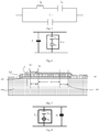
- Fig. 10 is a schematic structural diagram of a bulk acoustic resonator according to an exemplary embodiment of the present disclosure.
- the resonator includes a substrate 100, an acoustic mirror 200, a bottom electrode 300, a piezoelectric layer 400, a top electrode 500, an eave structure 600 and a beam structure 700.
- the region shown in B is an effective region of the resonator.
- the beam structure 700 is provided with a first beam portion (corresponding to the region where A in Fig.
- the beam structure 700 forms a beam gap BA
- the eave structure 600 has an eave gap WA
- the height of the eave gap is d
- the height of the beam gap is a
- the width of the eave gap is D
- the width of the first beam portion of the beam gap is A.
- the dimension of the eave gap (for example, the eave gap width) and the dimension of the first beam gap (for example, the first beam gap width) can be selected, so that the effective electromechanical coupling coefficient of the resonator provided with the eave structure and the beam structure is in the range of 95%-102% of the effective electromechanical coupling coefficient of a reference resonator (compared with the resonator provided with the eave structure and the beam structure, except for the eave structure and the beam structure, the other structures are completely the same), for example, 95%, 99%, 100%, 102%, and the like.
- the dimension of the eave gap (for example, the eave gap width) and the dimension of the first beam gap (for example, the first beam gap width) can also be selected, so that the effective electromechanical coupling coefficient of the resonator provided with the eave structure and the beam structure is different from the effective electromechanical coupling coefficient of the reference resonator (compared with the resonator provided with the eave structure and the beam structure, except for the eave structure and the beam structure, the other structures are completely the same).
- the first beam gap for example, the first beam gap width
- the effective electromechanical coupling coefficient of the resonator provided with the beam structure is different from the effective electromechanical coupling coefficient of the reference resonator (compared with the resonator provided with the beam structure, except for the beam structure, the other structures are completely the same).
- the present disclosure further proposes a method for controlling the effective electromechanical coupling coefficient of the bulk acoustic resonator, including the step of selecting the eave gap width and the first beam gap width, so that the effective electromechanical coupling coefficient of the resonator is in the range of 95%-102% of the effective electromechanical coupling coefficient of a reference resonator.
- the eave gap width and the first beam gap width are selected, so that the effective electromechanical coupling coefficient of the resonator is the same as the effective electromechanical coupling coefficient of the reference resonator.
- the beam gap height and/or the eave gap height can also be selected to adjust the effective electromechanical coupling coefficient.
- the present disclosure further proposes a filter, including: a series branch, including a plurality of series resonators; and a plurality of parallel branches, each parallel branch including at least one parallel resonator, wherein: the effective electromechanical coupling coefficient of at least one resonator among the at least one parallel resonator and the plurality of series resonators is different from the effective electromechanical coupling coefficients of the other resonators, and the at least one resonator is provided with the above-mentioned beam structure.
- At least two resonators among the at least one parallel resonator and the plurality of series resonators are provided with the above-mentioned beam structures and the above-mentioned eave structures, and the at least two resonators have different effective electromechanical coupling coefficients on the basis of the difference between the first beam gap width and the eave gap width.
- At least two resonators among the at least one parallel resonator and the plurality of series resonators are provided with the above-mentioned beam structures and the above-mentioned eave structures, and the at least two resonators have different effective electromechanical coupling coefficients on the basis of the difference between the first beam gap widths or the difference between the eave gap widths.
- the present disclosure further proposes a filter, including: a series branch, including a plurality of series resonators; and a plurality of parallel branches, each parallel branch including at least one parallel resonator, wherein: at least one resonator among the at least one parallel resonator and the plurality of series resonators includes the above-mentioned beam structure and the above-mentioned eave structure, and the effective electromechanical coupling coefficient of the at least one resonator is in the range of 95%-102% of the effective electromechanical coupling coefficient of a reference resonator.
- the effective electromechanical coupling coefficient of the at least one resonator is the same as the effective electromechanical coupling coefficient of the reference resonator.
- the material of the electrodes can be formed by gold (Au), tungsten (W), molybdenum (Mo), platinum (Pt), ruthenium (Ru), iridium (Ir), titanium tungsten (TiW), aluminum (Al), titanium (Ti), osmium (Os), magnesium (Mg), germanium (Ge), copper (Cu), aluminum (Al), chromium (Cr), arsenic doped gold and other similar metals.
- the material of the piezoelectric layer can be aluminum nitride (A1N), doped aluminum nitride (doped ALN), zinc oxide (ZnO), lead zirconate titanate (PZT), lithium niobate (LiNbO 3 ), quartz (Quartz), potassium niobate (KNbO 3 ) or lithium tantalate (LiTaO 3 ) and other materials, wherein the doped ALN contains at least one rare earth element, such as scandium (Sc), yttrium (Y), magnesium (Mg), titanium (Ti), lanthanum (La), cerium (Ce), praseodymium (Pr), neodymium (Nd), promethium (Pm), samarium (Sm), europium (Eu), gadolinium (Gd), terbium (Tb), dysprosium (Dy), holmium (Ho), erbium (Er), thul
- the material of the substrate includes, but is not limited to: single crystal silicon (Si), gallium arsenide (GaAs), sapphire, quartz, etc.
- the embodiments of the present disclosure further relate to electronic equipment, including the above-mentioned filter or resonator.
- electronic equipment includes, but is not limited to, intermediate products such as radio frequency front ends, filter amplifier modules, and terminal products such as mobile phones, WIFI, and drones.
Landscapes
- Physics & Mathematics (AREA)
- Acoustics & Sound (AREA)
- Piezo-Electric Or Mechanical Vibrators, Or Delay Or Filter Circuits (AREA)
Applications Claiming Priority (2)
| Application Number | Priority Date | Filing Date | Title |
|---|---|---|---|
| CN201811651302.XA CN111384911A (zh) | 2018-12-31 | 2018-12-31 | 基于梁檐尺寸调整声学谐振器性能的装置和方法 |
| PCT/CN2019/121109 WO2020140654A1 (zh) | 2018-12-31 | 2019-11-27 | 基于梁檐尺寸调整声学谐振器性能的装置和方法 |
Publications (2)
| Publication Number | Publication Date |
|---|---|
| EP3907884A1 true EP3907884A1 (de) | 2021-11-10 |
| EP3907884A4 EP3907884A4 (de) | 2022-02-23 |
Family
ID=71219517
Family Applications (1)
| Application Number | Title | Priority Date | Filing Date |
|---|---|---|---|
| EP19907323.0A Pending EP3907884A4 (de) | 2018-12-31 | 2019-11-27 | Vorrichtung und verfahren zur anpassung der leistung eines akustischen resonators auf der basis von strahl- und wellendimensionen |
Country Status (3)
| Country | Link |
|---|---|
| EP (1) | EP3907884A4 (de) |
| CN (1) | CN111384911A (de) |
| WO (1) | WO2020140654A1 (de) |
Families Citing this family (6)
| Publication number | Priority date | Publication date | Assignee | Title |
|---|---|---|---|---|
| US20220038076A1 (en) * | 2020-07-31 | 2022-02-03 | Wisol Co., Ltd. | Air-gap type film bulk acoustic resonator |
| CN113098426A (zh) * | 2021-03-15 | 2021-07-09 | 武汉大学 | 高频低损耗滤波器、谐振器及制备方法 |
| CN115378399A (zh) * | 2021-05-17 | 2022-11-22 | 诺思(天津)微系统有限责任公司 | 滤波器模组及其设计方法、多工器和通信设备 |
| KR20240068745A (ko) * | 2021-10-15 | 2024-05-17 | 우한 양시 마이크로 컴포넌츠 컴퍼니 리미티드 | 벌크 음향파 공진 구조 및 제조 방법, 음향파 소자 |
| CN113922781B (zh) * | 2021-10-15 | 2025-03-18 | 苏州汉天下电子有限公司 | 一种体声波谐振器以及通信器件 |
| CN120017000A (zh) * | 2025-01-16 | 2025-05-16 | 武汉敏声新技术有限公司 | 一种薄膜体声波谐振器和滤波器 |
Family Cites Families (9)
| Publication number | Priority date | Publication date | Assignee | Title |
|---|---|---|---|---|
| US9520856B2 (en) * | 2009-06-24 | 2016-12-13 | Avago Technologies General Ip (Singapore) Pte. Ltd. | Acoustic resonator structure having an electrode with a cantilevered portion |
| US8692631B2 (en) * | 2009-10-12 | 2014-04-08 | Hao Zhang | Bulk acoustic wave resonator and method of fabricating same |
| US9571064B2 (en) * | 2011-02-28 | 2017-02-14 | Avago Technologies General Ip (Singapore) Pte. Ltd. | Acoustic resonator device with at least one air-ring and frame |
| DE102012205033B4 (de) * | 2011-03-29 | 2020-01-30 | Avago Technologies International Sales Pte. Limited | Gestapelter akustischer Resonator, welcher eine Brücke aufweist |
| JP2013138425A (ja) * | 2011-12-27 | 2013-07-11 | Avago Technologies Wireless Ip (Singapore) Pte Ltd | ブリッジを備えるソリッドマウントバルク音響波共振器構造 |
| JP6400970B2 (ja) * | 2014-07-25 | 2018-10-03 | 太陽誘電株式会社 | フィルタおよびデュプレクサ |
| CN204481097U (zh) * | 2015-01-29 | 2015-07-15 | 河南易炫电子科技有限公司 | 一种用于无线通信的具有桥接器的耦合谐振滤波器 |
| CN110166014B (zh) * | 2018-02-11 | 2020-09-08 | 诺思(天津)微系统有限责任公司 | 体声波谐振器及其制造方法 |
| CN110061712B (zh) * | 2018-12-26 | 2023-10-20 | 天津大学 | 包括环形凸起梁檐结构的声学谐振器、滤波器和电子设备 |
-
2018
- 2018-12-31 CN CN201811651302.XA patent/CN111384911A/zh active Pending
-
2019
- 2019-11-27 WO PCT/CN2019/121109 patent/WO2020140654A1/zh not_active Ceased
- 2019-11-27 EP EP19907323.0A patent/EP3907884A4/de active Pending
Also Published As
| Publication number | Publication date |
|---|---|
| CN111384911A (zh) | 2020-07-07 |
| WO2020140654A1 (zh) | 2020-07-09 |
| EP3907884A4 (de) | 2022-02-23 |
Similar Documents
| Publication | Publication Date | Title |
|---|---|---|
| EP3907884A1 (de) | Vorrichtung und verfahren zur anpassung der leistung eines akustischen resonators auf der basis von strahl- und wellendimensionen | |
| Zheng et al. | Near 5-GHz longitudinal leaky surface acoustic wave devices on LiNbO 3/SiC substrates | |
| EP4033660A1 (de) | Volumenwellenresonator mit anpassungsschicht sowie filter und elektronische vorrichtung | |
| US6812619B1 (en) | Resonator structure and a filter comprising such a resonator structure | |
| US9461616B2 (en) | Bulk wave resonator having an aluminum nitride film containing scandium and ScAlN protective layer | |
| US8531087B2 (en) | Piezoelectric thin-film resonator with distributed concave or convex patterns | |
| CN113708739B (zh) | 一种声波滤波器 | |
| US11038486B2 (en) | Acoustic wave device | |
| US20170047907A1 (en) | Acoustic resonator device with an electrically-isolated layer of high-acoustic-impedance material interposed therein | |
| WO2020098487A1 (zh) | 带粗糙面体声波谐振器、滤波器和电子设备 | |
| CN111193489B (zh) | 体声波谐振器、滤波器和电子设备 | |
| EP4027517A1 (de) | Akustischer volumenwellenresonator mit piezoelektrischer schicht, der eine einsatzstruktur aufweist, sowie filter und elektronische vorrichtung | |
| US20240322783A1 (en) | Bulk acoustic wave resonance device and method for forming same, filtering device, and radio frequency front end device | |
| KR20080055740A (ko) | 압전 박막 공진기 및 필터 | |
| CN102801400A (zh) | 膜体声波谐振器、滤波器、双工器和模块 | |
| US20240291460A1 (en) | Bulk acoustic wave resonance device and method for forming same, filtering device, and radio frequency front end device | |
| CN111355466B (zh) | 具有多梁檐空隙的体声波谐振器、滤波器和电子设备 | |
| EP3905520A1 (de) | Volumenwellenresonator mit asymmetrischer elektrodendicke, filter und elektronisches gerät | |
| CN111355463A (zh) | 基于空腔尺寸调整有效机电耦合系数的装置 | |
| WO2022083352A1 (zh) | 体声波谐振器及组件、滤波器、电子设备 | |
| CN114696773B (zh) | 体声波谐振器及制造方法、滤波器及电子设备 | |
| EP3905521A1 (de) | Resonator mit erweiterungsstruktur am verbindungsabschnitt der oberen elektrode, filter und elektronische vorrichtung | |
| CN113228506A (zh) | 表面声波谐振器和包括其的多路复用器 | |
| CN111262547B (zh) | 体声波谐振器、mems器件、滤波器和电子设备 | |
| CN114641932A (zh) | 使用瑞利模式的薄膜表面声波器件 |
Legal Events
| Date | Code | Title | Description |
|---|---|---|---|
| STAA | Information on the status of an ep patent application or granted ep patent |
Free format text: STATUS: THE INTERNATIONAL PUBLICATION HAS BEEN MADE |
|
| PUAI | Public reference made under article 153(3) epc to a published international application that has entered the european phase |
Free format text: ORIGINAL CODE: 0009012 |
|
| STAA | Information on the status of an ep patent application or granted ep patent |
Free format text: STATUS: REQUEST FOR EXAMINATION WAS MADE |
|
| 17P | Request for examination filed |
Effective date: 20210802 |
|
| AK | Designated contracting states |
Kind code of ref document: A1 Designated state(s): AL AT BE BG CH CY CZ DE DK EE ES FI FR GB GR HR HU IE IS IT LI LT LU LV MC MK MT NL NO PL PT RO RS SE SI SK SM TR |
|
| A4 | Supplementary search report drawn up and despatched |
Effective date: 20220125 |
|
| RIC1 | Information provided on ipc code assigned before grant |
Ipc: H03H 9/17 20060101ALI20220119BHEP Ipc: H03H 9/02 20060101AFI20220119BHEP |
|
| DAV | Request for validation of the european patent (deleted) | ||
| DAX | Request for extension of the european patent (deleted) | ||
| STAA | Information on the status of an ep patent application or granted ep patent |
Free format text: STATUS: EXAMINATION IS IN PROGRESS |
|
| 17Q | First examination report despatched |
Effective date: 20240517 |