EP3907454A1 - Grate bar for a pelletizing or sintering machine - Google Patents
Grate bar for a pelletizing or sintering machine Download PDFInfo
- Publication number
- EP3907454A1 EP3907454A1 EP20173517.2A EP20173517A EP3907454A1 EP 3907454 A1 EP3907454 A1 EP 3907454A1 EP 20173517 A EP20173517 A EP 20173517A EP 3907454 A1 EP3907454 A1 EP 3907454A1
- Authority
- EP
- European Patent Office
- Prior art keywords
- grate
- grate bar
- crossbeam
- interlocking means
- bars
- Prior art date
- Legal status (The legal status is an assumption and is not a legal conclusion. Google has not performed a legal analysis and makes no representation as to the accuracy of the status listed.)
- Withdrawn
Links
Images


Classifications
-
- F—MECHANICAL ENGINEERING; LIGHTING; HEATING; WEAPONS; BLASTING
- F27—FURNACES; KILNS; OVENS; RETORTS
- F27D—DETAILS OR ACCESSORIES OF FURNACES, KILNS, OVENS OR RETORTS, IN SO FAR AS THEY ARE OF KINDS OCCURRING IN MORE THAN ONE KIND OF FURNACE
- F27D3/00—Charging; Discharging; Manipulation of charge
- F27D3/12—Travelling or movable supports or containers for the charge
- F27D3/123—Furnace cars
-
- F—MECHANICAL ENGINEERING; LIGHTING; HEATING; WEAPONS; BLASTING
- F27—FURNACES; KILNS; OVENS; RETORTS
- F27B—FURNACES, KILNS, OVENS OR RETORTS IN GENERAL; OPEN SINTERING OR LIKE APPARATUS
- F27B21/00—Open or uncovered sintering apparatus; Other heat-treatment apparatus of like construction
- F27B21/02—Sintering grates or tables
-
- F—MECHANICAL ENGINEERING; LIGHTING; HEATING; WEAPONS; BLASTING
- F27—FURNACES; KILNS; OVENS; RETORTS
- F27D—DETAILS OR ACCESSORIES OF FURNACES, KILNS, OVENS OR RETORTS, IN SO FAR AS THEY ARE OF KINDS OCCURRING IN MORE THAN ONE KIND OF FURNACE
- F27D3/00—Charging; Discharging; Manipulation of charge
- F27D3/12—Travelling or movable supports or containers for the charge
-
- F—MECHANICAL ENGINEERING; LIGHTING; HEATING; WEAPONS; BLASTING
- F27—FURNACES; KILNS; OVENS; RETORTS
- F27D—DETAILS OR ACCESSORIES OF FURNACES, KILNS, OVENS OR RETORTS, IN SO FAR AS THEY ARE OF KINDS OCCURRING IN MORE THAN ONE KIND OF FURNACE
- F27D3/00—Charging; Discharging; Manipulation of charge
- F27D2003/0034—Means for moving, conveying, transporting the charge in the furnace or in the charging facilities
- F27D2003/0059—Means for moving, conveying, transporting the charge in the furnace or in the charging facilities comprising tracks, e.g. rails and wagon
- F27D2003/0061—Means for moving, conveying, transporting the charge in the furnace or in the charging facilities comprising tracks, e.g. rails and wagon with means for changing track
-
- Y—GENERAL TAGGING OF NEW TECHNOLOGICAL DEVELOPMENTS; GENERAL TAGGING OF CROSS-SECTIONAL TECHNOLOGIES SPANNING OVER SEVERAL SECTIONS OF THE IPC; TECHNICAL SUBJECTS COVERED BY FORMER USPC CROSS-REFERENCE ART COLLECTIONS [XRACs] AND DIGESTS
- Y02—TECHNOLOGIES OR APPLICATIONS FOR MITIGATION OR ADAPTATION AGAINST CLIMATE CHANGE
- Y02P—CLIMATE CHANGE MITIGATION TECHNOLOGIES IN THE PRODUCTION OR PROCESSING OF GOODS
- Y02P10/00—Technologies related to metal processing
- Y02P10/25—Process efficiency
Definitions
- the present invention generally relates to a device used in a sintering or pelletizing machine, and more particularly to a grate bar for mounting in arrays of adjacent grate bars on a pallet car of a sintering or pelletizing machine.
- bulk material to be treated for example iron ore
- a travelling grate comprising an endless chain of pallet cars.
- the pallet cars filled with the bulk material are driven through various treatment stations for thermally treating the material, which is thereafter discharged from the machine as heat-treated product.
- the pallet cars are turned over to discharge the heat-treated product lying on the grates by gravity and the cars are guided upside down back to the beginning of the treatment stations of the sintering or pelletizing machine, where they are turned over again, ready to receive bulk material thereon.
- the sintering or pelletizing machine thus operates in a cycle as an endless grate carriage chain.
- the top of the pallet cars comprises a grate on which bulk material is charged. During one thermal treatment, heating of the bulk material is achieved by blowing a flow of hot gas either upwards or downwards through the bulk material and the grate of the pallet car.
- the grate therefore generally comprises a plurality of grate bars separated by gaps to allow the flow of gas therethrough.
- the grate bars are arranged parallel to each other in rows and columns so as to cover the entire charging surface of the pallet car.
- a grate bar typically comprises a main supporting crossbeam for receiving the bulk material thereon.
- the crossbeam further comprises connection means, generally in the form of tongue and groove design, to secure the grate bar to a frame element of the pallet car.
- the individual grate bars are generally loosely arranged on the pallet car, one beside the other, so as to maintain a degree of movement. Such an arrangement allows the grate to self-clean. Indeed, the movement of the grate bars with respect to each other when the pallet cars are turned upside down allows for bulk material stuck between two neighbouring grate bars to loosen and fall off the grate.
- Connection means between the grate bars and the pallet cars are configured in a tongue and groove design at each end of the grate bar, to prevent the grate bars from falling out when the pallet cars are turned over.
- connection between the grate bars and the pallet car generally comprises an expansion space, in all three directions, allowing thermal expansion of the grate bars.
- pallet cars are subject to very harsh thermal conditions inside the machine, pallet cars undergo substantial mechanical wear, particularly caused by the highly abrasive surface of the bulk material. As a result, the grate bars must regularly be replaced.
- Typical signs of wear on grate bars show a decreasing volume of the top crossbeam due to the impact of the material combined with high temperature and airflow.
- the grate bar eventually loses its initial shape and the predetermined gap between grate bars is no longer maintained.
- grate bars loosely connected to the pallet car move vertically relative to the car. Then, at the beginning of the line, the pallet car is turned back to its regular position with the grate bars falling down into their functional places. Nonetheless, bulk particles or any spillage stuck in spaces between the grate bars may disturb the correct vertical positioning of the grate bars. Some grate bars may not lay down properly and remain protruding from the otherwise generally plane surface of the grate carriage. The thereby formed irregular top surface of the pallet car increases localized wear due to abrasive effects. The vertically misaligned grate bars further interfere with the cleaning process of the upper surface of the pallet car arrangement.
- US 1,704,027 discloses a grate for sintering plants.
- the grate comprises a plurality of grate bars connected to a grate carriage.
- the grate bars are equipped with transversal spacers in their transversal direction in order to maintain a gap between neighbouring grate bars.
- the grate bars are connected to one another by a longitudinal overlapping end. This overlapping end limits movements of the bars during the turning over of the pallet car in order to have a better weight distribution and prevent the grate bars from rocking the pallet car prematurely until it has been rotated to a predetermined position. Once passed the predetermined rotating position, the grate bars will move with considerable force to more effectively break up and dislodge any material that may clog the spaces between grate bars.
- the invention overcomes the above discussed deficiencies and disadvantages by providing a grate bar for a pallet car of a sintering or pelletizing machine.
- the grate bar is preferably mounted in arrays of adjacent grate bars on the pallet car.
- the grate bar comprises an elongate crossbeam extending in a longitudinal direction of a horizontal plane, with a middle section between two opposite end sections.
- the crossbeam has a generally rectangular cross-section with a support surface for receiving bulk material thereon, an opposite base surface, and peripheral surfaces for contacting adjacent grate bars.
- the crossbeam further comprises two legs to vertically secure the grate bar to the pallet car. Each leg may have a hook shape with a vertical branch essentially perpendicular to the lower surface, and a horizontal branch essentially parallel to the lower surface and extending outwardly.
- the end sections of the crossbeam comprise first interlocking means, the latter being shaped and arranged such that the first interlocking means cooperate with first interlocking means of grate bars of a neighbouring row of grate bars; thereby limiting relative translations of two neighbouring grate bars in at least a vertical and a horizontal orientation.
- the first interlocking means has a triangular cross-section in a horizontal plane.
- the end sections of the grate bars of one row of grate bars engage with the end sections of the grate bars of a neighbouring row of grate bars.
- This not only limits individual grate bars in their movement in the longitudinal and transversal direction of the grate bar, but also in their rotational movement. Indeed, the grate bars are prevented from tilting or canting.
- the predefined gap between neighbouring grate bars is essentially maintained. Undesired localised gap increases between neighbouring grate bars can be avoided.
- orientation is used to refer to a global orientation that may be represented by a line in the three dimensional space.
- direction will then refer to one of the two directions possibly pointed by an orientation.
- the first interlocking means preferably limits the translation of the grate bar in both directions of the horizontal orientation.
- the position of the first interlocking means in the end section of the grate bar allows for a gap to be provided between two adjacent grate bars in the middle section. This gap forms a gas passage allowing a gas stream to flow through the grate.
- the triangular cross-section of the first interlocking means has an apex, which is located on a medial line between two side surfaces of the crossbeam.
- a medial line is parallel to the two side surfaces and arranged to be half-way between the two side surfaces.
- the medial line extends beyond the crossbeam in the longitudinal direction.
- the shape of the triangular cross-section is that of an equilateral or isosceles triangle.
- the first interlocking means is a V-shaped first interlocking element.
- first interlocking means wherein the apex is not on such a medial line, thereby providing a first interlocking means having a shape corresponding to an acute triangle or even right triangle.
- the opposite end of the neighbouring grate bar then has its first interlocking element of a complementary shape.
- the peripheral surfaces of the middle section of the grate bar respectively comprise at least one spacer extending in a transversal direction. While it is not excluded to provide more than one spacer on the longitudinal side surfaces, the grate bars are however advantageously provided with a single spacer in the centre of the middle section.
- the spacers are arranged such that two spacers of neighbouring grate bars come into contact with each other, thereby defining the distance between the crossbeams, i.e. the gap between grate bars through which gas is blown.
- Such a spacer thus defines a constant gap between two adjacent grate bars, in order to maintain the air flow through an array of grate bars, while avoiding particles of material from falling though the grate.
- the spacer is preferably arranged in an upper region of the crossbeam because this section is exposed to major wear. During the lifetime of the grate bar, this upper part and the spacer will be reduced in width. However, due to the overlapping of the end sections of the grate bars, between neighbouring rows, the grate bars can be readjusted to maintain the desired gap through which gas is blown.
- the spacer may be of any appropriate shape. Preferably, however, the spacer has a shape narrowing in direction of the incoming gas flow. Such a spacer may e.g. be triangular or half-circular, with their pointy side or rounded side facing upwards for machines in which gas is blown through the grate bars from above or downwards for machines in which gas is blown through the grate bars from below.
- Further interlocking means may be provided to secure a grate bar relative to an adjacent grate bar.
- Such further interlocking means may comprise one or more interlocking elements.
- the interlocking means is configured to overlap with an interlocking means of a neighbouring grate bar in the longitudinal orientation of the grate bar row.
- the grate bar is provided with second interlocking means, which may comprise a first protrusion and a corresponding second protrusion arranged to overlap a first protrusion of a neighbouring grate bar.
- the first and second protrusions protrude on the end sections of the crossbeam in a transversal direction.
- the first and second protrusions are positions in such a way that, when two grate bars are positioned in a grate, the one side of the first protrusion of one grate bar faces one side of the second protrusion of the other grate bar.
- the first and second protrusions thereby form an abutment between each other in the longitudinal direction of the grate bar, thereby limiting movement of the grate bars in the longitudinal direction.
- the first and second protrusions may be of rectangular cross-section.
- the first and second protrusions may be of triangular cross-section.
- the protrusions may be arranged so as to not only limiting movement of the grate bars in the longitudinal direction, but also in the vertical direction.
- the grate bar is provided with third interlocking means on the longitudinal sides of the legs of the grate bar.
- the third interlocking means may comprise an upper lip on one side of a leg and a lower lip on the other side of the leg; the upper and lower lips being dimensioned and positioned in a staggered arrangement such that, in use, an upper lip of one grate bar cooperate with a lower lip of a neighbouring grate bar form an abutment in a vertical, height direction of the grate bar
- the upper and lower lips are preferably arranged on the horizontal branch of the leg.
- the third interlocking means may comprise a first U-shaped lip arranged on one side of the grate bar and a second U-shaped lip arranged on the other side of the grate bar.
- Each U-shaped lip extends over the horizontal branch of the leg, over the vertical branch of the leg and over an end portion of the crossbeam.
- the second U-shaped lip has a shape corresponding to that of the first U-shaped lip but offset such that, in use, a first U-shaped lip of one grate bar cooperates with a second U-shaped lip of a neighbouring grate bar to form an abutment in a vertical, height direction and in the longitudinal direction of the grate bar.
- the upper surface of the crossbeam has concave or convex form depending on what type of machine the grate bar is used in.
- the grate bars for use in pelletizing machines are therefore advantageously provided with a convex upper surface to increase the amount of bulk material on the end sections of the crossbeam, thereby better protecting the latter against wear.
- sinter machines In sinter machines, on the other hand, most wear occurs to the middle section of the crossbeam.
- the grate bars for use in sinter machines are therefore advantageously provided with a concave upper surface to increase the amount of bulk material in the centre of the crossbeam, thereby better protecting the middle section is against wear.
- the cross-section of the crossbeam may, in the middle section thereof, be narrowing in direction of the lower surface.
- Such a narrowing middle section not only reduces the weight of the grate bar, but also helps to guide the gas flow to or from the region under the grate bar.
- the grate bar according to the present invention may further comprise a stiffening rib arranged on the lower surface of the crossbeam, extending between the two legs, and preferably extending further down the inner sides of the legs.
- a stiffening rib can increase the robustness of the grate bar and thus further extend its lifetime.
- a recess may be arranged in the centre of the middle section to further reduce weight of the grate bar.
- the invention concerns a pallet car of a sintering or pelletizing machine, the pallet car comprising a grate with plurality of arrays of adjacent grate bars creating a plane surface for receiving bulk material thereon, the grate bars being grate bars as described above.
- top, bottom, above, below, vertical, horizontal will be used with reference to the direction in the figures for ease of explanation.
- the (horizontal) longitudinal direction L, the (horizontal) transversal direction T and the (vertical) height direction H are indicated on the figures.
- the grate bar is adapted to be mounted in arrays of adjacent grate bars on a frame element of a pallet car, not shown, and used in a sintering or pelletizing machine.
- a sintering or pelletizing machine used in a sintering or pelletizing machine.
- Figs 1 to 3 shows a grate bar 10 according to one embodiment, the grate bar 10 having an elongate crossbeam 12 extending in a longitudinal direction of a horizontal plane, and legs 14 attached to the crossbeam 12 to vertically secure the bar 10 to a frame of the pallet car (not shown).
- the grate bar 10 is virtually divided into three sections, a first end section 16, a second end section 18 opposite the first end section 16 and a middle section 20 between the two end sections 16, 18.
- the crossbeam 12 extends from the first end section 16, via the middle section 20, to the second end section 18 and has a generally rectangular cross-section. It comprises an upper surface 22 for receiving bulk material thereon, and an opposite lower surface 24 that is, in use, in contact with the frame of the pallet car.
- the crossbeam 12 also comprises peripheral surfaces joining the upper and lower surfaces 22, 24.
- the peripheral surfaces are, in use, facing adjacent grate bars.
- the peripheral surfaces comprise two longitudinal side surfaces 28 and, at each tip of the end sections 16, 18, two transversal end surfaces 30.
- peripheral side surfaces 28, particularly in the middle section of the crossbeam, define a fluid passage for a flow of gas between two adjacent grate bars; i.e. through the grate.
- the legs 14 are attached to the lower surface 24 at each end section 16, 18, and have a hook shape with a vertical branch 34 essentially perpendicular to the lower surface 24, and a horizontal branch 36 essentially parallel to the lower surface 24 and extending outwardly.
- the grate bar 10 is mounted on the pallet car, with a frame element of the pallet car interposed between the lower surface 24 in each end section 16, 18 and the horizontal branch 36 of the leg 14 of the grate bar 10, thereby limiting the translation of the grate bar 10 in a vertical direction.
- the grate bar is supported on the pallet car by having its lower surface at the end sections resting on the frame of the pallet car.
- the grate bar lifts off the frame through gravity.
- the grate bar is prevented from dropping off the pallet car by means of locking bars engaging the horizontal branches 36 of the legs 14.
- the end sections 16, 18 of the crossbeam 12 comprise first interlocking means 38 configured to be in overlapping contact with first interlocking means 38 of a neighbouring grate bar, thereby limiting relative translations of two neighbouring grate bars in any horizontal direction.
- the grate bar is then prevented from moving in a longitudinal direction L and in a transversal direction T.
- the first interlocking means 38 also limits the rotational movement of the grate bars 10 in the plane of the array, i.e. the horizontal plane.
- Fig.4 shows a view from above onto an array of grate bars 10 as arranged on a pallet car.
- This shows a first row 40 of grate bars 10 and a second row 42 of grate bars 10.
- the transversal end surfaces 30 of the second end section 18 of the grate bars 10 of the first row 40 engage with the transversal end surfaces 30 of the first end section 16 of the grate bars 10 of the second row 42.
- a gap 44 is arranged between neighbouring grate bars 10 to allow thermal expansion of the grate bars 10 in a longitudinal and transverse direction L, T.
- the first interlocking elements 38 have triangular shape, with the apex 48 of the triangle being located on the medial line M between the two parallel side surfaces 28, thereby forming an equilateral or isosceles triangle (V-shaped first interlocking element).
- the grate bars 10 of two neighbouring rows 40, 42 of grate bars are thus arranged, as shown in Fig.4 , in a staggered configuration.
- the first interlocking elements 38 can also have a triangular shape representing an acute triangle or even right triangle.
- the opposite end of the neighbouring grate bar 10 of course needs its first interlocking element to be of complementary shape.
- the grate bar 10 further comprises a spacer 50 arranged on each of the longitudinal side surfaces 28 of the crossbeam 12.
- the spacers 50 are provided in the centre of the middle section 20 and extend in a transversal direction T of the grate bar 10.
- the spacers 50 are arranged such that two spacers 50 of neighbouring grate bars 10 come into contact with each other, thereby defining the distance between the crossbeams 12, i.e. the gas passage 52 between grate bars through which gas is blown.
- the spacer 50 may be of any appropriate shape, such as e.g. rectangular, triangular, circular or, as shown in Figs 1 to 3 , half-circular.
- the rounded edge of the spacer 50 faces the incoming stream of gas, offering less resistance to the stream of gas blown through the grate bars. In machines where gas is blown through the grate bars from above, the rounded edge of the spacer 50 faces upwards as shown in Figs 1 to 3 . In machines where gas is blown through the grate bars from below, the rounded edge of the spacer 50 will of course face downwards.
- each longitudinal side surface 28 comprises a single spacer 50. However, it is not excluded to provide more than one spacer on the longitudinal side surfaces 28.
- the spacers 50 improve the parallelism of two adjacent grate bars and ensure that the gas passage 52 (as seen on Fig.4 ) defined by the gap between the crossbeams 12, remains of essentially constant width.
- the spacers 50 divide the gas passage 52 in two smaller passages.
- the grate bar 10 further comprises second interlocking means 60 on the longitudinal side surfaces 28 near the end sections 16, 18.
- the second interlocking means 60 comprise a first protrusion 62 protruding from the side surfaces 28 of the second end section 18 of the crossbeam 12, positioned at a predefined distance from the end surface 30. Its corresponding second interlocking element 60 is formed by a second protrusion 64 on the opposite side surface 28 of the crossbeam 12 in the second end section 18.
- the second protrusion 64 is positioned at an increased distance from the end surface 30 as the first protrusion 62.
- a corresponding arrangement of first and second protrusions 62, 64 is provided at the first end section 16.
- the protrusions 62, 64 are arranged in close proximity to protrusions 64, 62 a neighbouring grate bar.
- the protrusions 62, 64 thus form an abutment between each other in the longitudinal direction L, in order to avoid misalignments of the grate bars.
- Figs 1 to 3 show protrusions 62, 64 with a rectangular shape, it is also possible to provide other shapes.
- Triangular protrusions as shown in Fig.5 , may e.g. be arranged such that the protrusions not only form an abutment in the longitudinal direction L, but also in the vertical height direction H.
- the triangular protrusions shown in dotted outline are located on the other side of the grate bar and are represented here to show their cooperation with the triangular protrusions of a neighbouring grate bar.
- the grate bar 10 further comprises third interlocking means 70 on the longitudinal sides of the legs 14 of the grate bar 10.
- the third interlocking means is formed by a horizontal upper lip 72 on the horizontal branch 36 of the leg 14.
- the third interlocking means is formed by a horizontal lower lip 74 on the horizontal branch 36 of the leg 14.
- the lower lip 74 is arranged at a lower position than the upper lip 72 and positioned longitudinally, such that, as the grate bar 10 is disposed in an array of grate bars, the upper and lower lips 72, 74 form an abutment for each other in the vertical height direction H.
- the position of the upper and lower lips 72, 74 are inverted on the other leg of the grate bar.
- the middle section 20 of the crossbeam 12 may have a cross-section narrowing down towards the lower surface 24. This allows reducing the weight of the grate bar 10 and guiding the gas flow to or from the region under the grate bar.
- a stiffening rib 80 is arranged on the lower surface 24 of the crossbeam 12.
- the stiffening rib 80 extends between the two legs 14 and down the inner sides of the legs 14.
- Such a stiffening rib 80 improves the rigidity of the grate bar 10 with limited quantity of material.
- the stiffening rib 80 comprises a recess 82, which further reduces material weight.
- the recess 82 also helps reduce stress peaks in critical areas of the grate bar 10.
- the recess 82 may be an enlarged rounded section as shown in Fig.2 .
- the recess 82 may be a smaller, pointier area as e.g. shown in Fig.5 .
- the third interlocking means 70 is, on one side of the grate bar, formed by a first U-shaped lip 90 which extends over the horizontal branch 36 of the leg 14, over the vertical branch 34 of the leg 14 and over the end portion 16 of the crossbeam 12 up to the transversal end surface 30.
- a corresponding, second U-shaped lip 92 is arranged on the other side of the grate bar.
- This second U-shaped lip 92 is however slightly offset. Indeed, on the horizontal branch 36 of the leg 14 it is arranged slightly lower, on the end portion 16 of the crossbeam 12 it is arranged slightly higher and on the vertical branch 34 of the leg 14 it is arranged slightly more inwardly.
- Both U-shaped lips 90, 92 of two neighbouring grate bars act as abutment for each other to prevent movement of the grate bar 10 in the longitudinal direction L and the vertical height direction H.
- the grate bar 10 of Fig.6 also shows a crossbeam 12 with an essentially concave upper surface 22.
- a concave upper surface may be advantageous to prevent wear of the grate bar in pelletizing machines.
- the second and third interlocking means 60, 70 are not in contact with each other. They only enter into contact when one of the grate bars enters into a slight misalignment. The second and third interlocking means 60, 70 then prevent the grate bar 10 form further misalignments.
- the third interlocking means 70 particularly the U-shaped lip 90, 92 according to the third embodiment of Fig.6 , forms a type of labyrinth seal preventing any bulk material from reaching the grate bar supports upon which the grate bars 10 rest.
- the upper surface of the crossbeam may have concave or convex form to increase its resistance to wear.
- sinter machines In sinter machines, on the other hand, most wear occurs to the middle section 20 of the crossbeam 12.
- the grate bars for use in sinter machines are therefore advantageously provided with a concave upper surface, such as shown in Fig.6 .
- the middle section is better protected against wear.
Landscapes
- Engineering & Computer Science (AREA)
- Mechanical Engineering (AREA)
- General Engineering & Computer Science (AREA)
- Manufacture And Refinement Of Metals (AREA)
Abstract
A grate bar (10) for mounting in arrays of adjacent grate bars in a pallet car of a sintering or pelletizing machine, wherein the grate bar (10) comprises an elongate crossbeam (12) extending in a longitudinal direction of a horizontal plane, with a middle section (20) between two opposite end sections (16, 18). The crossbeam (12) has a generally rectangular cross-section with an upper surface (22) for receiving bulk material thereon, an opposite lower surface (24), and peripheral surfaces (28, 30) for facing adjacent grate bars. The crossbeam (12) further comprises two legs (14) to vertically secure the grate bar (10) to the pallet car. The end sections (16, 18) of the crossbeam (12) comprise first interlocking means (38), the first interlocking means (38) being shaped and arranged such that they cooperate with first interlocking means of grate bars of a neighbouring row of grate bars; thereby limiting relative translations of two neighbouring grate bars in at least a vertical and a horizontal orientation. The first interlocking means (38) have a triangular cross-section in a horizontal plane.
Description
- The present invention generally relates to a device used in a sintering or pelletizing machine, and more particularly to a grate bar for mounting in arrays of adjacent grate bars on a pallet car of a sintering or pelletizing machine.
- In sintering or pelletizing machines, bulk material to be treated, for example iron ore, is charged onto a travelling grate comprising an endless chain of pallet cars. The pallet cars filled with the bulk material are driven through various treatment stations for thermally treating the material, which is thereafter discharged from the machine as heat-treated product.
- After the treatment stations, the pallet cars are turned over to discharge the heat-treated product lying on the grates by gravity and the cars are guided upside down back to the beginning of the treatment stations of the sintering or pelletizing machine, where they are turned over again, ready to receive bulk material thereon. The sintering or pelletizing machine thus operates in a cycle as an endless grate carriage chain.
- The top of the pallet cars comprises a grate on which bulk material is charged. During one thermal treatment, heating of the bulk material is achieved by blowing a flow of hot gas either upwards or downwards through the bulk material and the grate of the pallet car. The grate therefore generally comprises a plurality of grate bars separated by gaps to allow the flow of gas therethrough. The grate bars are arranged parallel to each other in rows and columns so as to cover the entire charging surface of the pallet car. A grate bar typically comprises a main supporting crossbeam for receiving the bulk material thereon. The crossbeam further comprises connection means, generally in the form of tongue and groove design, to secure the grate bar to a frame element of the pallet car.
- The individual grate bars are generally loosely arranged on the pallet car, one beside the other, so as to maintain a degree of movement. Such an arrangement allows the grate to self-clean. Indeed, the movement of the grate bars with respect to each other when the pallet cars are turned upside down allows for bulk material stuck between two neighbouring grate bars to loosen and fall off the grate. Connection means between the grate bars and the pallet cars are configured in a tongue and groove design at each end of the grate bar, to prevent the grate bars from falling out when the pallet cars are turned over.
- Due to the high thermal variations inside the sintering or pelletizing machine, the connection between the grate bars and the pallet car generally comprises an expansion space, in all three directions, allowing thermal expansion of the grate bars.
- Since the pallet cars are subject to very harsh thermal conditions inside the machine, pallet cars undergo substantial mechanical wear, particularly caused by the highly abrasive surface of the bulk material. As a result, the grate bars must regularly be replaced.
- Typical signs of wear on grate bars show a decreasing volume of the top crossbeam due to the impact of the material combined with high temperature and airflow. The grate bar eventually loses its initial shape and the predetermined gap between grate bars is no longer maintained.
- In use, particles of sinter or pellets get stuck in the gaps between grate bars and tend to push one grate bar toward a neighbouring grate bar. The grate bars thus lose their parallel positioning and become tilted relative to one another. As a consequence, the gaps between the grate bars comprise wider and tighter areas. In the wider areas, more and bigger particles may get stuck, thus increasing the abrasion phenomenon and reducing the lifetime of the grate bars and of the pallet car in general. In tighter areas, there is no space left to permit thermal expansion of the grate bar, thereby reducing its robustness and provoking material damage. Additionally, the negative effect from bulk material falling through the gaps between grate bars can have an impact on downstream equipment, such as e.g. windboxes, ducts, fans and sealings.
- When the pallet car is turned upside down, grate bars loosely connected to the pallet car move vertically relative to the car. Then, at the beginning of the line, the pallet car is turned back to its regular position with the grate bars falling down into their functional places. Nonetheless, bulk particles or any spillage stuck in spaces between the grate bars may disturb the correct vertical positioning of the grate bars. Some grate bars may not lay down properly and remain protruding from the otherwise generally plane surface of the grate carriage. The thereby formed irregular top surface of the pallet car increases localized wear due to abrasive effects. The vertically misaligned grate bars further interfere with the cleaning process of the upper surface of the pallet car arrangement.
- Though the loose connection between the grate bars and the pallet car allows easy replacement operations of the grate bars, these operations are cost and time consuming. There is therefore a need for improving the durability of the grate bars.
- Solutions are known in the art in order to reduce wear of the grate bars. For example,
US 1,704,027 discloses a grate for sintering plants. The grate comprises a plurality of grate bars connected to a grate carriage. In this example, the grate bars are equipped with transversal spacers in their transversal direction in order to maintain a gap between neighbouring grate bars. The grate bars are connected to one another by a longitudinal overlapping end. This overlapping end limits movements of the bars during the turning over of the pallet car in order to have a better weight distribution and prevent the grate bars from rocking the pallet car prematurely until it has been rotated to a predetermined position. Once passed the predetermined rotating position, the grate bars will move with considerable force to more effectively break up and dislodge any material that may clog the spaces between grate bars. - This solution limits clogging of the gaps between the grate bars and attempts to prevent the height differences when the pallet car comes back to its original position. Nevertheless, there is no solution to avoid a lateral or longitudinal misalignment of the grate bars or to slow down the wear of the grate bars.
- Another solution is suggested in
US 2,949,289 A , which discloses a grate bar for a sintering or pelletizing machine, wherein the grate bar cleanses itself of material lodged between the grate and the pallet car frame. The end of the grate bar comprises a wedge shape to push away sinter particles. As the pallet car is turned back to its original position, the grate bars move back down to their support element on the pallet car, pushing away any particles below the end of the grate bars to ensure that the grate bars do not get stuck in a higher vertical position. - In the latter solution, there is again means to improve the vertical positioning of the grate bar, but there is still a risk of horizontal misalignment leading to increased wear of the grate bars.
- It is therefore desirable to provide a solution to improve the durability of a grate bar, in particular to reduce the increased wear caused by misalignments of the grate bars on a pallet car.
- The invention overcomes the above discussed deficiencies and disadvantages by providing a grate bar for a pallet car of a sintering or pelletizing machine. The grate bar is preferably mounted in arrays of adjacent grate bars on the pallet car. The grate bar comprises an elongate crossbeam extending in a longitudinal direction of a horizontal plane, with a middle section between two opposite end sections.
- The crossbeam has a generally rectangular cross-section with a support surface for receiving bulk material thereon, an opposite base surface, and peripheral surfaces for contacting adjacent grate bars. The crossbeam further comprises two legs to vertically secure the grate bar to the pallet car. Each leg may have a hook shape with a vertical branch essentially perpendicular to the lower surface, and a horizontal branch essentially parallel to the lower surface and extending outwardly.
- According to the invention, the end sections of the crossbeam comprise first interlocking means, the latter being shaped and arranged such that the first interlocking means cooperate with first interlocking means of grate bars of a neighbouring row of grate bars; thereby limiting relative translations of two neighbouring grate bars in at least a vertical and a horizontal orientation. The first interlocking means has a triangular cross-section in a horizontal plane.
- Due to the triangular shape of the first interlocking means, the end sections of the grate bars of one row of grate bars engage with the end sections of the grate bars of a neighbouring row of grate bars. This not only limits individual grate bars in their movement in the longitudinal and transversal direction of the grate bar, but also in their rotational movement. Indeed, the grate bars are prevented from tilting or canting. Thus, the predefined gap between neighbouring grate bars is essentially maintained. Undesired localised gap increases between neighbouring grate bars can be avoided.
- In the context of the invention, the term orientation is used to refer to a global orientation that may be represented by a line in the three dimensional space. The term direction will then refer to one of the two directions possibly pointed by an orientation.
- The first interlocking means preferably limits the translation of the grate bar in both directions of the horizontal orientation. The position of the first interlocking means in the end section of the grate bar allows for a gap to be provided between two adjacent grate bars in the middle section. This gap forms a gas passage allowing a gas stream to flow through the grate.
- Preferably, the triangular cross-section of the first interlocking means has an apex, which is located on a medial line between two side surfaces of the crossbeam. Such a medial line is parallel to the two side surfaces and arranged to be half-way between the two side surfaces. The medial line extends beyond the crossbeam in the longitudinal direction. With the apex lying on such a medial line, the shape of the triangular cross-section is that of an equilateral or isosceles triangle. Thus, the first interlocking means is a V-shaped first interlocking element. It is however not excluded to provide a first interlocking means wherein the apex is not on such a medial line, thereby providing a first interlocking means having a shape corresponding to an acute triangle or even right triangle. The opposite end of the neighbouring grate bar then has its first interlocking element of a complementary shape.
- Preferably, the peripheral surfaces of the middle section of the grate bar respectively comprise at least one spacer extending in a transversal direction. While it is not excluded to provide more than one spacer on the longitudinal side surfaces, the grate bars are however advantageously provided with a single spacer in the centre of the middle section.
- The spacers are arranged such that two spacers of neighbouring grate bars come into contact with each other, thereby defining the distance between the crossbeams, i.e. the gap between grate bars through which gas is blown. Such a spacer thus defines a constant gap between two adjacent grate bars, in order to maintain the air flow through an array of grate bars, while avoiding particles of material from falling though the grate. The spacer is preferably arranged in an upper region of the crossbeam because this section is exposed to major wear. During the lifetime of the grate bar, this upper part and the spacer will be reduced in width. However, due to the overlapping of the end sections of the grate bars, between neighbouring rows, the grate bars can be readjusted to maintain the desired gap through which gas is blown.
- The spacer may be of any appropriate shape. Preferably, however, the spacer has a shape narrowing in direction of the incoming gas flow. Such a spacer may e.g. be triangular or half-circular, with their pointy side or rounded side facing upwards for machines in which gas is blown through the grate bars from above or downwards for machines in which gas is blown through the grate bars from below.
- Further interlocking means may be provided to secure a grate bar relative to an adjacent grate bar. Such further interlocking means may comprise one or more interlocking elements. When two adjacent grate bars move vertically, for example due to the turning of the pallet car, the overlapping of the interlocking means ensures that there is no vertical misalignment of the grate bars. As they overlap in at least a vertical and a horizontal orientation, most of the grate bar misalignments are avoided.
- Preferably, the interlocking means is configured to overlap with an interlocking means of a neighbouring grate bar in the longitudinal orientation of the grate bar row.
- According to an embodiment of the invention, the grate bar is provided with second interlocking means, which may comprise a first protrusion and a corresponding second protrusion arranged to overlap a first protrusion of a neighbouring grate bar. The first and second protrusions protrude on the end sections of the crossbeam in a transversal direction. The first and second protrusions are positions in such a way that, when two grate bars are positioned in a grate, the one side of the first protrusion of one grate bar faces one side of the second protrusion of the other grate bar. The first and second protrusions thereby form an abutment between each other in the longitudinal direction of the grate bar, thereby limiting movement of the grate bars in the longitudinal direction.
- The first and second protrusions may be of rectangular cross-section. Alternatively, the first and second protrusions may be of triangular cross-section. In the latter case, the protrusions may be arranged so as to not only limiting movement of the grate bars in the longitudinal direction, but also in the vertical direction.
- According to an embodiment of the invention, the grate bar is provided with third interlocking means on the longitudinal sides of the legs of the grate bar.
- In one embodiment, the third interlocking means may comprise an upper lip on one side of a leg and a lower lip on the other side of the leg; the upper and lower lips being dimensioned and positioned in a staggered arrangement such that, in use, an upper lip of one grate bar cooperate with a lower lip of a neighbouring grate bar form an abutment in a vertical, height direction of the grate bar The upper and lower lips are preferably arranged on the horizontal branch of the leg.
- In another embodiment, the third interlocking means may comprise a first U-shaped lip arranged on one side of the grate bar and a second U-shaped lip arranged on the other side of the grate bar. Each U-shaped lip extends over the horizontal branch of the leg, over the vertical branch of the leg and over an end portion of the crossbeam. The second U-shaped lip has a shape corresponding to that of the first U-shaped lip but offset such that, in use, a first U-shaped lip of one grate bar cooperates with a second U-shaped lip of a neighbouring grate bar to form an abutment in a vertical, height direction and in the longitudinal direction of the grate bar.
- Preferably, the upper surface of the crossbeam has concave or convex form depending on what type of machine the grate bar is used in.
- Indeed, in pelletizing machines, it has been found that most wear occurs to the end sections of the crossbeam. The grate bars for use in pelletizing machines are therefore advantageously provided with a convex upper surface to increase the amount of bulk material on the end sections of the crossbeam, thereby better protecting the latter against wear.
- In sinter machines, on the other hand, most wear occurs to the middle section of the crossbeam. The grate bars for use in sinter machines are therefore advantageously provided with a concave upper surface to increase the amount of bulk material in the centre of the crossbeam, thereby better protecting the middle section is against wear.
- The cross-section of the crossbeam may, in the middle section thereof, be narrowing in direction of the lower surface. Such a narrowing middle section not only reduces the weight of the grate bar, but also helps to guide the gas flow to or from the region under the grate bar.
- The grate bar according to the present invention may further comprise a stiffening rib arranged on the lower surface of the crossbeam, extending between the two legs, and preferably extending further down the inner sides of the legs. Such a stiffening rib can increase the robustness of the grate bar and thus further extend its lifetime. A recess may be arranged in the centre of the middle section to further reduce weight of the grate bar.
- According to another aspect, the invention concerns a pallet car of a sintering or pelletizing machine, the pallet car comprising a grate with plurality of arrays of adjacent grate bars creating a plane surface for receiving bulk material thereon, the grate bars being grate bars as described above.
- Further details and advantages of the present invention will be apparent from the following detailed description of not limiting embodiments with reference to the attached drawings, wherein:
- Fig.1
- is a perspective view of a first preferred embodiment of a grate bar according to the invention;
- Fig.2
- is a side view of the grate bar of
Fig.1 ; - Fig.3
- is a top view of the grate bar of
Fig.1 ; - Fig.4
- is a top view of an arrangement of grate bars of
Fig.1 ; - Fig.5
- is a side view of a second preferred embodiment of a grate bar according to the invention; and
- Fig.6
- is a side view of a third preferred embodiment of a grate bar according to the invention.
- Preferred embodiments showing non limiting examples of the grate bar according to the invention will now be described with reference to
Figs 1 to 6 . It is understood that features that are not described in detail in one embodiment can be considered similar to the feature of previous embodiments. Also, in order not to overload the figures, some reference signs denoting identical features have not been repeated on all figures. - In the description below, the terms "top, bottom, above, below, vertical, horizontal" will be used with reference to the direction in the figures for ease of explanation. The (horizontal) longitudinal direction L, the (horizontal) transversal direction T and the (vertical) height direction H are indicated on the figures.
- The grate bar is adapted to be mounted in arrays of adjacent grate bars on a frame element of a pallet car, not shown, and used in a sintering or pelletizing machine. In the following description of the grate bar, the interaction between neighbouring grate bars in an array will be mentioned to clarify the functions of the features.
-
Figs 1 to 3 shows agrate bar 10 according to one embodiment, thegrate bar 10 having anelongate crossbeam 12 extending in a longitudinal direction of a horizontal plane, andlegs 14 attached to thecrossbeam 12 to vertically secure thebar 10 to a frame of the pallet car (not shown). Thegrate bar 10 is virtually divided into three sections, afirst end section 16, asecond end section 18 opposite thefirst end section 16 and a middle section 20 between the twoend sections - The
crossbeam 12 extends from thefirst end section 16, via the middle section 20, to thesecond end section 18 and has a generally rectangular cross-section. It comprises anupper surface 22 for receiving bulk material thereon, and an oppositelower surface 24 that is, in use, in contact with the frame of the pallet car. Thecrossbeam 12 also comprises peripheral surfaces joining the upper andlower surfaces end sections - In an array of grate bars, the peripheral side surfaces 28, particularly in the middle section of the crossbeam, define a fluid passage for a flow of gas between two adjacent grate bars; i.e. through the grate.
- The
legs 14 are attached to thelower surface 24 at eachend section vertical branch 34 essentially perpendicular to thelower surface 24, and ahorizontal branch 36 essentially parallel to thelower surface 24 and extending outwardly. - In use, the
grate bar 10 is mounted on the pallet car, with a frame element of the pallet car interposed between thelower surface 24 in eachend section horizontal branch 36 of theleg 14 of thegrate bar 10, thereby limiting the translation of thegrate bar 10 in a vertical direction. - The skilled person will understand that when the pallet car enters the sintering or pelletizing machine and carries bulk material through thermal treatment stations, the grate bar is supported on the pallet car by having its lower surface at the end sections resting on the frame of the pallet car. When the pallet car is turned over, the grate bar lifts off the frame through gravity. The grate bar is prevented from dropping off the pallet car by means of locking bars engaging the
horizontal branches 36 of thelegs 14. - As shown in
Figs 1 to 3 , theend sections crossbeam 12 comprise first interlocking means 38 configured to be in overlapping contact with first interlocking means 38 of a neighbouring grate bar, thereby limiting relative translations of two neighbouring grate bars in any horizontal direction. Indeed, the grate bar is then prevented from moving in a longitudinal direction L and in a transversal direction T. The first interlocking means 38 also limits the rotational movement of the grate bars 10 in the plane of the array, i.e. the horizontal plane. -
Fig.4 shows a view from above onto an array of grate bars 10 as arranged on a pallet car. This shows afirst row 40 of grate bars 10 and asecond row 42 of grate bars 10. The transversal end surfaces 30 of thesecond end section 18 of the grate bars 10 of thefirst row 40 engage with the transversal end surfaces 30 of thefirst end section 16 of the grate bars 10 of thesecond row 42. Agap 44 is arranged between neighbouring grate bars 10 to allow thermal expansion of the grate bars 10 in a longitudinal and transverse direction L, T. - In the embodiment shown in
Fig.4 (alsoFigs 1-3 ), thefirst interlocking elements 38 have triangular shape, with the apex 48 of the triangle being located on the medial line M between the two parallel side surfaces 28, thereby forming an equilateral or isosceles triangle (V-shaped first interlocking element). The grate bars 10 of two neighbouringrows Fig.4 , in a staggered configuration. It will be understood, however, that thefirst interlocking elements 38 can also have a triangular shape representing an acute triangle or even right triangle. The opposite end of the neighbouringgrate bar 10 of course needs its first interlocking element to be of complementary shape. - Referring back to
Figs 1 to 3 , thegrate bar 10 further comprises aspacer 50 arranged on each of the longitudinal side surfaces 28 of thecrossbeam 12. Thespacers 50 are provided in the centre of the middle section 20 and extend in a transversal direction T of thegrate bar 10. Thespacers 50 are arranged such that twospacers 50 of neighbouring grate bars 10 come into contact with each other, thereby defining the distance between thecrossbeams 12, i.e. thegas passage 52 between grate bars through which gas is blown. - The
spacer 50 may be of any appropriate shape, such as e.g. rectangular, triangular, circular or, as shown inFigs 1 to 3 , half-circular. The rounded edge of thespacer 50 faces the incoming stream of gas, offering less resistance to the stream of gas blown through the grate bars. In machines where gas is blown through the grate bars from above, the rounded edge of thespacer 50 faces upwards as shown inFigs 1 to 3 . In machines where gas is blown through the grate bars from below, the rounded edge of thespacer 50 will of course face downwards. - Preferably, each longitudinal side surface 28 comprises a
single spacer 50. However, it is not excluded to provide more than one spacer on the longitudinal side surfaces 28. - The
spacers 50 improve the parallelism of two adjacent grate bars and ensure that the gas passage 52 (as seen onFig.4 ) defined by the gap between thecrossbeams 12, remains of essentially constant width. Thespacers 50 divide thegas passage 52 in two smaller passages. - The
grate bar 10 further comprises second interlocking means 60 on the longitudinal side surfaces 28 near theend sections first protrusion 62 protruding from the side surfaces 28 of thesecond end section 18 of thecrossbeam 12, positioned at a predefined distance from theend surface 30. Its corresponding second interlocking element 60 is formed by asecond protrusion 64 on the opposite side surface 28 of thecrossbeam 12 in thesecond end section 18. Thesecond protrusion 64 is positioned at an increased distance from theend surface 30 as thefirst protrusion 62. A corresponding arrangement of first andsecond protrusions first end section 16. - As the
grate bar 10 is disposed in an array of grate bars, theprotrusions protrusions 64, 62 a neighbouring grate bar. Theprotrusions - While
Figs 1 to 3 show protrusions Fig.5 , may e.g. be arranged such that the protrusions not only form an abutment in the longitudinal direction L, but also in the vertical height direction H. The triangular protrusions shown in dotted outline are located on the other side of the grate bar and are represented here to show their cooperation with the triangular protrusions of a neighbouring grate bar. - The
grate bar 10 further comprises third interlocking means 70 on the longitudinal sides of thelegs 14 of thegrate bar 10. On one of the longitudinal sides, the third interlocking means is formed by a horizontalupper lip 72 on thehorizontal branch 36 of theleg 14. On the other longitudinal side, the third interlocking means is formed by a horizontallower lip 74 on thehorizontal branch 36 of theleg 14. Thelower lip 74 is arranged at a lower position than theupper lip 72 and positioned longitudinally, such that, as thegrate bar 10 is disposed in an array of grate bars, the upper andlower lips lower lips - As can further be seen from
Fig.1 , the middle section 20 of thecrossbeam 12 may have a cross-section narrowing down towards thelower surface 24. This allows reducing the weight of thegrate bar 10 and guiding the gas flow to or from the region under the grate bar. - Also, a stiffening
rib 80 is arranged on thelower surface 24 of thecrossbeam 12. The stiffeningrib 80 extends between the twolegs 14 and down the inner sides of thelegs 14. Such a stiffeningrib 80 improves the rigidity of thegrate bar 10 with limited quantity of material. In the centre of the middle section 20, the stiffeningrib 80 comprises arecess 82, which further reduces material weight. Therecess 82 also helps reduce stress peaks in critical areas of thegrate bar 10. Therecess 82 may be an enlarged rounded section as shown inFig.2 . Alternatively, therecess 82 may be a smaller, pointier area as e.g. shown inFig.5 . - An alternative grate bar according to a third embodiment is shown in
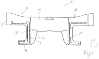
Fig.6 . According to this embodiment, the third interlocking means 70 is, on one side of the grate bar, formed by a firstU-shaped lip 90 which extends over thehorizontal branch 36 of theleg 14, over thevertical branch 34 of theleg 14 and over theend portion 16 of thecrossbeam 12 up to thetransversal end surface 30. A corresponding, second U-shaped lip 92 is arranged on the other side of the grate bar. This second U-shaped lip 92 is however slightly offset. Indeed, on thehorizontal branch 36 of theleg 14 it is arranged slightly lower, on theend portion 16 of thecrossbeam 12 it is arranged slightly higher and on thevertical branch 34 of theleg 14 it is arranged slightly more inwardly. BothU-shaped lips 90, 92 of two neighbouring grate bars act as abutment for each other to prevent movement of thegrate bar 10 in the longitudinal direction L and the vertical height direction H. - The
grate bar 10 ofFig.6 also shows acrossbeam 12 with an essentially concaveupper surface 22. Such a concave upper surface may be advantageous to prevent wear of the grate bar in pelletizing machines. - In normal operation, the second and third interlocking means 60, 70 are not in contact with each other. They only enter into contact when one of the grate bars enters into a slight misalignment. The second and third interlocking means 60, 70 then prevent the
grate bar 10 form further misalignments. The third interlocking means 70, particularly theU-shaped lip 90, 92 according to the third embodiment ofFig.6 , forms a type of labyrinth seal preventing any bulk material from reaching the grate bar supports upon which the grate bars 10 rest. - The upper surface of the crossbeam may have concave or convex form to increase its resistance to wear.
- In pelletizing machines, it has been found that most wear occurs to the
end sections crossbeam 12. The grate bars for use in pelletizing machines are therefore advantageously provided with a convex upper surface, such as shown inFigs 2 or5 . By increasing the amount of material on the end sections of the crossbeam, the latter are better protected against wear. - In sinter machines, on the other hand, most wear occurs to the middle section 20 of the
crossbeam 12. The grate bars for use in sinter machines are therefore advantageously provided with a concave upper surface, such as shown inFig.6 . By increasing the amount of material in the centre of the crossbeam, the middle section is better protected against wear.List of Reference Symbols L longitudinal direction 40 first row of grate bars T transversal direction 42 second row of grate bars H height direction 44 gap M medial line 48 apex of triangle shape 10 grate bar 50 spacer 12 crossbeam 52 gas passage 14 legs 60 second interlocking means 16 first end section 62 first protrusion 18 second end section 64 second protrusion 20 middle section 70 third interlocking means 22 upper surface 72 upper lip 24 lower surface 74 lower lip 28 longitudinal side surfaces 80 stiffening rib 30 transversal end surfaces 82 recess 34 vertical branch of leg 90 first U-shaped lip 36 horizontal branch of leg 92 second U-shaped lip 38 first interlocking means
Claims (15)
- A grate bar (10) for mounting in arrays of adjacent grate bars in a pallet car of a sintering or pelletizing machine, said grate bar (10) comprising an elongate crossbeam (12) extending in a longitudinal direction of a horizontal plane, with a middle section (20) between two opposite end sections (16, 18),
wherein said crossbeam (12) has a generally rectangular cross-section with an upper surface (22) for receiving bulk material thereon, an opposite lower surface (24), and peripheral surfaces (28, 30) for facing adjacent grate bars;
wherein said crossbeam (12) comprises two legs (14) to vertically secure said grate bar (10) to said pallet car; and
wherein said end sections (16, 18) of said crossbeam (12) comprise first interlocking means (38), said first interlocking means (38) being shaped and arranged such that they cooperate with first interlocking means of grate bars of a neighbouring row of grate bars; thereby limiting relative translations of two neighbouring grate bars in at least a vertical and a horizontal orientation,
wherein said first interlocking means (38) have a triangular cross-section in a horizontal plane. - Grate bar according to claim 1, wherein an apex (48) of said triangular cross-section is located on a medial line (M) between two side surfaces (28) of the crossbeam (12).
- Grate bar according to any one of the preceding claims, wherein said middle sections (20) of said crossbeam (12) comprise a spacer (50), the spacers (50) being positioned and dimensioned to define, in use, a gap (44) between neighbouring crossbeams forming a gas passage (52).
- Grate bar according to claim 3, wherein a single spacer (50) is located in the centre of the middle section (20) on either side of the crossbeam (12).
- Grate bar according to claim 3 or 4, wherein said spacer (50) has a shape narrowing in direction of the incoming gas flow.
- Grate bar according to any one of the preceding claims, further comprising second interlocking means (60), said second interlocking means (60) comprising first and second protrusions (62, 64) protruding from said side surfaces (28) of the first and second end sections (16, 18) of the crossbeam (12), said first and second protrusions (62, 64) being dimensioned and positioned in a staggered arrangement such that, in use, first protrusions (62) of one grate bar (10) cooperate with second protrusions (64) of a neighbouring grate bar 10 to form an abutment in a longitudinal direction (L) of the grate bar (10).
- Grate bar according to claim 6, wherein said first and second protrusions (62, 64) have rectangular or triangular cross-section.
- Grate bar according to any one of the preceding claims, further comprising third interlocking means (70), said third interlocking means (70) being arranged on said leg 14, said leg (14) comprising a vertical branch (34) essentially perpendicular to the crossbeam (12), and a horizontal branch (36) essentially parallel to the crossbeam (12) and extending outwardly in a longitudinal direction (L) of the grate bar (10).
- Grate bar according to claim 8, wherein said third interlocking means (70) comprises an upper lip (72) on one side of a leg (14) and a lower lip (74) on the other side of the leg (14); the upper and lower lips (72, 74) being dimensioned and positioned in a staggered arrangement such that, in use, an upper lip (72) of one grate bar (10) cooperate with a lower lip (74) of a neighbouring grate bar (10) to form an abutment in a vertical, height direction (H) of the grate bar (10), said upper and lower lips (72, 74) being arranged on said horizontal branch (36) of said leg (14).
- Grate bar according to claim 8, wherein said third interlocking means (70) comprises- a first U-shaped lip (90) arranged on one side of the grate bar, said first U-shaped lip 90 extending over the horizontal branch (36) of the leg (14), over the vertical branch (34) of the leg (14) and over an end portion (16, 18) of the crossbeam (12),- a second U-shaped lip (92) arranged on the other side of the grate bar, said second U-shaped lip (92) having a shape corresponding to that of said first U-shaped lip (90) but offset such that, in use, a first U-shaped lip (90) of one grate bar (10) cooperates with a second U-shaped lip (92) of a neighbouring grate bar (10) to form an abutment in a vertical, height direction (H) and longitudinal direction (L) of the grate bar (10).
- Grate bar according to any one of the preceding claims, wherein the upper surface (22) of the crossbeam (12) has concave or convex form.
- Grate bar according to any one of the preceding claims, wherein, in said middle section (20), said crossbeam (12) has cross-section narrowing down towards the lower surface (24).
- Grate bar according to any one of the preceding claims, further comprising a stiffening rib (80) is arranged on the lower surface 24 of the crossbeam (12), wherein said stiffening rib (80) preferably extends down inner sides of said legs (14).
- Grate bar according to claim 13, wherein said stiffening rib (80) comprises a recess (82) in the centre of the middle section (20).
- Pallet car of a sintering or pelletizing machine, said pallet car comprising a grate with plurality of arrays of adjacent grate bars (10) creating a plane surface for receiving bulk material thereon, comprising grate bars (10) according to any one of said preceding claims.
Priority Applications (8)
| Application Number | Priority Date | Filing Date | Title |
|---|---|---|---|
| EP20173517.2A EP3907454A1 (en) | 2020-05-07 | 2020-05-07 | Grate bar for a pelletizing or sintering machine |
| MX2022013924A MX2022013924A (en) | 2020-05-07 | 2021-05-05 | Grate bar for a pelletizing or sintering machine. |
| PCT/EP2021/061887 WO2021224339A1 (en) | 2020-05-07 | 2021-05-05 | Grate bar for a pelletizing or sintering machine |
| US17/998,083 US12492866B2 (en) | 2020-05-07 | 2021-05-05 | Grate bar for a pelletizing or sintering machine |
| CN202180033530.4A CN115516266A (en) | 2020-05-07 | 2021-05-05 | Grate bar for pellets or sintering machines |
| EP21723264.4A EP4146998B1 (en) | 2020-05-07 | 2021-05-05 | Grate bar for a pelletizing or sintering machine |
| CA3176447A CA3176447A1 (en) | 2020-05-07 | 2021-05-05 | Grate bar for a pelletizing or sintering machine |
| BR112022022301A BR112022022301A2 (en) | 2020-05-07 | 2021-05-05 | GRILL BAR, GRILL BAR ARRANGEMENT, PALLET TROLLEY OF A SINTERING OR PELLETIZING MACHINE AND SINTERING OR PELLETIZING MACHINE |
Applications Claiming Priority (1)
| Application Number | Priority Date | Filing Date | Title |
|---|---|---|---|
| EP20173517.2A EP3907454A1 (en) | 2020-05-07 | 2020-05-07 | Grate bar for a pelletizing or sintering machine |
Publications (1)
| Publication Number | Publication Date |
|---|---|
| EP3907454A1 true EP3907454A1 (en) | 2021-11-10 |
Family
ID=70617005
Family Applications (2)
| Application Number | Title | Priority Date | Filing Date |
|---|---|---|---|
| EP20173517.2A Withdrawn EP3907454A1 (en) | 2020-05-07 | 2020-05-07 | Grate bar for a pelletizing or sintering machine |
| EP21723264.4A Active EP4146998B1 (en) | 2020-05-07 | 2021-05-05 | Grate bar for a pelletizing or sintering machine |
Family Applications After (1)
| Application Number | Title | Priority Date | Filing Date |
|---|---|---|---|
| EP21723264.4A Active EP4146998B1 (en) | 2020-05-07 | 2021-05-05 | Grate bar for a pelletizing or sintering machine |
Country Status (7)
| Country | Link |
|---|---|
| US (1) | US12492866B2 (en) |
| EP (2) | EP3907454A1 (en) |
| CN (1) | CN115516266A (en) |
| BR (1) | BR112022022301A2 (en) |
| CA (1) | CA3176447A1 (en) |
| MX (1) | MX2022013924A (en) |
| WO (1) | WO2021224339A1 (en) |
Families Citing this family (1)
| Publication number | Priority date | Publication date | Assignee | Title |
|---|---|---|---|---|
| CN116273315B (en) * | 2023-03-28 | 2024-10-11 | 湖南德尚源耐磨工业有限公司 | Single-roller crusher matched with sintering machine and grate plate replacement method of single-roller crusher |
Citations (8)
| Publication number | Priority date | Publication date | Assignee | Title |
|---|---|---|---|---|
| US1704027A (en) | 1928-02-25 | 1929-03-05 | John E Greenawalt | Grate for sintering pans |
| US2949289A (en) | 1958-02-01 | 1960-08-16 | Metallgesellschaft Ag | Grate bar for sintering apparatus |
| SU851064A1 (en) * | 1979-04-12 | 1981-07-30 | Норильский Вечерний Индустриальныйинститут | Grate bar |
| CN202719872U (en) * | 2012-08-10 | 2013-02-06 | 邯郸慧桥复合材料科技有限公司 | A kind of sintering machine grate |
| US20170016672A1 (en) * | 2015-07-17 | 2017-01-19 | Cast Steel Products Lp, By Its General Partner Cast Steel Products Gp Ltd. | Grate Bar for a Pallet Car |
| SE1551587A1 (en) * | 2015-12-03 | 2017-06-04 | Luossavaara-Kiirunavaara Ab | Grating rod for a grating wagon at a sintering machine and a grating wagon |
| SE1700073A1 (en) * | 2016-04-28 | 2017-10-29 | Ferro Balt Plus Joint Stock Company | Furnace grate |
| CN111089487A (en) * | 2019-12-10 | 2020-05-01 | 唐山市鸿泉矿山机械有限公司 | A sintered anti-blocking grating |
Family Cites Families (4)
| Publication number | Priority date | Publication date | Assignee | Title |
|---|---|---|---|---|
| DE2109948C3 (en) * | 1971-03-02 | 1974-01-24 | Polysius Ag, 4723 Neubeckum | Traveling grate |
| BR7900232U (en) * | 1999-02-03 | 2000-09-05 | Vale Do Rio Doce Co | Grid bar improvement for pelletizing and sintering furnaces |
| KR100833007B1 (en) * | 2001-12-22 | 2008-05-27 | 주식회사 포스코 | Great Bardle for Better Breathability in Sintering Machines |
| CN208254225U (en) * | 2018-04-24 | 2018-12-18 | 尹镇涛 | A kind of online self-cleaning type sintering machine fire grate bar |
-
2020
- 2020-05-07 EP EP20173517.2A patent/EP3907454A1/en not_active Withdrawn
-
2021
- 2021-05-05 CN CN202180033530.4A patent/CN115516266A/en active Pending
- 2021-05-05 CA CA3176447A patent/CA3176447A1/en active Pending
- 2021-05-05 WO PCT/EP2021/061887 patent/WO2021224339A1/en not_active Ceased
- 2021-05-05 BR BR112022022301A patent/BR112022022301A2/en unknown
- 2021-05-05 MX MX2022013924A patent/MX2022013924A/en unknown
- 2021-05-05 EP EP21723264.4A patent/EP4146998B1/en active Active
- 2021-05-05 US US17/998,083 patent/US12492866B2/en active Active
Patent Citations (8)
| Publication number | Priority date | Publication date | Assignee | Title |
|---|---|---|---|---|
| US1704027A (en) | 1928-02-25 | 1929-03-05 | John E Greenawalt | Grate for sintering pans |
| US2949289A (en) | 1958-02-01 | 1960-08-16 | Metallgesellschaft Ag | Grate bar for sintering apparatus |
| SU851064A1 (en) * | 1979-04-12 | 1981-07-30 | Норильский Вечерний Индустриальныйинститут | Grate bar |
| CN202719872U (en) * | 2012-08-10 | 2013-02-06 | 邯郸慧桥复合材料科技有限公司 | A kind of sintering machine grate |
| US20170016672A1 (en) * | 2015-07-17 | 2017-01-19 | Cast Steel Products Lp, By Its General Partner Cast Steel Products Gp Ltd. | Grate Bar for a Pallet Car |
| SE1551587A1 (en) * | 2015-12-03 | 2017-06-04 | Luossavaara-Kiirunavaara Ab | Grating rod for a grating wagon at a sintering machine and a grating wagon |
| SE1700073A1 (en) * | 2016-04-28 | 2017-10-29 | Ferro Balt Plus Joint Stock Company | Furnace grate |
| CN111089487A (en) * | 2019-12-10 | 2020-05-01 | 唐山市鸿泉矿山机械有限公司 | A sintered anti-blocking grating |
Also Published As
| Publication number | Publication date |
|---|---|
| CA3176447A1 (en) | 2021-11-11 |
| WO2021224339A1 (en) | 2021-11-11 |
| US20230228490A1 (en) | 2023-07-20 |
| MX2022013924A (en) | 2023-02-09 |
| EP4146998A1 (en) | 2023-03-15 |
| EP4146998C0 (en) | 2024-05-01 |
| EP4146998B1 (en) | 2024-05-01 |
| CN115516266A (en) | 2022-12-23 |
| BR112022022301A2 (en) | 2022-12-20 |
| US12492866B2 (en) | 2025-12-09 |
Similar Documents
| Publication | Publication Date | Title |
|---|---|---|
| US10670266B2 (en) | Grate bar for a furnace comprising engaging means | |
| RU2116600C1 (en) | Cooler for cooling material consisting of macroparticles | |
| US6296110B1 (en) | Conveying system for conveying products, and slide-over device | |
| US5174747A (en) | Grate plate | |
| PL195078B1 (en) | Disintegrated material cooler | |
| EP4146998B1 (en) | Grate bar for a pelletizing or sintering machine | |
| EP3571455B1 (en) | Side wall of a pallet car for a travelling grate machine, pallet car comprising such a side wall and method for converting a pallet car | |
| KR20130111933A (en) | Grid plate | |
| KR200439982Y1 (en) | Fire grate | |
| US6290493B1 (en) | Grate plate for cooler | |
| US5882189A (en) | Sliding grate for a burnt-material-cooling unit, and grating plate therefor | |
| EA043201B1 (en) | GRATE FOR GRANULATED OR SINTERING MACHINE | |
| JP7545110B2 (en) | Raw material input chute | |
| CA3192278A1 (en) | Grate block with rising nose | |
| US6824736B1 (en) | Pusher furnace rails with plate-shaped sliding supports and sliding shoes | |
| US5766001A (en) | Grate element for a grate surface, e.g. in a clinker cooler | |
| US6312252B1 (en) | Cooler for combustion products | |
| JP3590359B2 (en) | Apron conveyor | |
| US3719354A (en) | Travelling grate machines | |
| KR102597019B1 (en) | Air-cooled grate for incinerator | |
| JP5243884B2 (en) | Sintering machine pallet | |
| JPH04180514A (en) | Skid button of heating furnace | |
| SU1046592A1 (en) | Bogie of travelling roasting machine | |
| SU1130726A1 (en) | Conveyer roasting machine car | |
| US20180363985A1 (en) | Grate Plate for a Grate Cooler |
Legal Events
| Date | Code | Title | Description |
|---|---|---|---|
| PUAI | Public reference made under article 153(3) epc to a published international application that has entered the european phase |
Free format text: ORIGINAL CODE: 0009012 |
|
| STAA | Information on the status of an ep patent application or granted ep patent |
Free format text: STATUS: THE APPLICATION HAS BEEN PUBLISHED |
|
| AK | Designated contracting states |
Kind code of ref document: A1 Designated state(s): AL AT BE BG CH CY CZ DE DK EE ES FI FR GB GR HR HU IE IS IT LI LT LU LV MC MK MT NL NO PL PT RO RS SE SI SK SM TR |
|
| B565 | Issuance of search results under rule 164(2) epc |
Effective date: 20200824 |
|
| STAA | Information on the status of an ep patent application or granted ep patent |
Free format text: STATUS: THE APPLICATION IS DEEMED TO BE WITHDRAWN |
|
| 18D | Application deemed to be withdrawn |
Effective date: 20220511 |