EP3907445A1 - Condenser subassembly with integrated flash tank - Google Patents
Condenser subassembly with integrated flash tank Download PDFInfo
- Publication number
- EP3907445A1 EP3907445A1 EP20173152.8A EP20173152A EP3907445A1 EP 3907445 A1 EP3907445 A1 EP 3907445A1 EP 20173152 A EP20173152 A EP 20173152A EP 3907445 A1 EP3907445 A1 EP 3907445A1
- Authority
- EP
- European Patent Office
- Prior art keywords
- condenser
- vessel
- chamber
- flash tank
- subassembly
- Prior art date
- Legal status (The legal status is an assumption and is not a legal conclusion. Google has not performed a legal analysis and makes no representation as to the accuracy of the status listed.)
- Pending
Links
Images


Classifications
-
- F—MECHANICAL ENGINEERING; LIGHTING; HEATING; WEAPONS; BLASTING
- F25—REFRIGERATION OR COOLING; COMBINED HEATING AND REFRIGERATION SYSTEMS; HEAT PUMP SYSTEMS; MANUFACTURE OR STORAGE OF ICE; LIQUEFACTION SOLIDIFICATION OF GASES
- F25B—REFRIGERATION MACHINES, PLANTS OR SYSTEMS; COMBINED HEATING AND REFRIGERATION SYSTEMS; HEAT PUMP SYSTEMS
- F25B39/00—Evaporators; Condensers
- F25B39/04—Condensers
-
- F—MECHANICAL ENGINEERING; LIGHTING; HEATING; WEAPONS; BLASTING
- F25—REFRIGERATION OR COOLING; COMBINED HEATING AND REFRIGERATION SYSTEMS; HEAT PUMP SYSTEMS; MANUFACTURE OR STORAGE OF ICE; LIQUEFACTION SOLIDIFICATION OF GASES
- F25B—REFRIGERATION MACHINES, PLANTS OR SYSTEMS; COMBINED HEATING AND REFRIGERATION SYSTEMS; HEAT PUMP SYSTEMS
- F25B1/00—Compression machines, plants or systems with non-reversible cycle
- F25B1/10—Compression machines, plants or systems with non-reversible cycle with multi-stage compression
-
- F—MECHANICAL ENGINEERING; LIGHTING; HEATING; WEAPONS; BLASTING
- F25—REFRIGERATION OR COOLING; COMBINED HEATING AND REFRIGERATION SYSTEMS; HEAT PUMP SYSTEMS; MANUFACTURE OR STORAGE OF ICE; LIQUEFACTION SOLIDIFICATION OF GASES
- F25B—REFRIGERATION MACHINES, PLANTS OR SYSTEMS; COMBINED HEATING AND REFRIGERATION SYSTEMS; HEAT PUMP SYSTEMS
- F25B13/00—Compression machines, plants or systems, with reversible cycle
-
- F—MECHANICAL ENGINEERING; LIGHTING; HEATING; WEAPONS; BLASTING
- F25—REFRIGERATION OR COOLING; COMBINED HEATING AND REFRIGERATION SYSTEMS; HEAT PUMP SYSTEMS; MANUFACTURE OR STORAGE OF ICE; LIQUEFACTION SOLIDIFICATION OF GASES
- F25B—REFRIGERATION MACHINES, PLANTS OR SYSTEMS; COMBINED HEATING AND REFRIGERATION SYSTEMS; HEAT PUMP SYSTEMS
- F25B41/00—Fluid-circulation arrangements
- F25B41/30—Expansion means; Dispositions thereof
- F25B41/39—Dispositions with two or more expansion means arranged in series, i.e. multi-stage expansion, on a refrigerant line leading to the same evaporator
-
- F—MECHANICAL ENGINEERING; LIGHTING; HEATING; WEAPONS; BLASTING
- F25—REFRIGERATION OR COOLING; COMBINED HEATING AND REFRIGERATION SYSTEMS; HEAT PUMP SYSTEMS; MANUFACTURE OR STORAGE OF ICE; LIQUEFACTION SOLIDIFICATION OF GASES
- F25B—REFRIGERATION MACHINES, PLANTS OR SYSTEMS; COMBINED HEATING AND REFRIGERATION SYSTEMS; HEAT PUMP SYSTEMS
- F25B49/00—Arrangement or mounting of control or safety devices
- F25B49/02—Arrangement or mounting of control or safety devices for compression type machines, plants or systems
-
- F—MECHANICAL ENGINEERING; LIGHTING; HEATING; WEAPONS; BLASTING
- F25—REFRIGERATION OR COOLING; COMBINED HEATING AND REFRIGERATION SYSTEMS; HEAT PUMP SYSTEMS; MANUFACTURE OR STORAGE OF ICE; LIQUEFACTION SOLIDIFICATION OF GASES
- F25B—REFRIGERATION MACHINES, PLANTS OR SYSTEMS; COMBINED HEATING AND REFRIGERATION SYSTEMS; HEAT PUMP SYSTEMS
- F25B2339/00—Details of evaporators; Details of condensers
- F25B2339/04—Details of condensers
- F25B2339/047—Water-cooled condensers
-
- F—MECHANICAL ENGINEERING; LIGHTING; HEATING; WEAPONS; BLASTING
- F25—REFRIGERATION OR COOLING; COMBINED HEATING AND REFRIGERATION SYSTEMS; HEAT PUMP SYSTEMS; MANUFACTURE OR STORAGE OF ICE; LIQUEFACTION SOLIDIFICATION OF GASES
- F25B—REFRIGERATION MACHINES, PLANTS OR SYSTEMS; COMBINED HEATING AND REFRIGERATION SYSTEMS; HEAT PUMP SYSTEMS
- F25B2400/00—Component parts or details not otherwise provided for in this subclass
- F25B2400/13—Economisers
-
- F—MECHANICAL ENGINEERING; LIGHTING; HEATING; WEAPONS; BLASTING
- F25—REFRIGERATION OR COOLING; COMBINED HEATING AND REFRIGERATION SYSTEMS; HEAT PUMP SYSTEMS; MANUFACTURE OR STORAGE OF ICE; LIQUEFACTION SOLIDIFICATION OF GASES
- F25B—REFRIGERATION MACHINES, PLANTS OR SYSTEMS; COMBINED HEATING AND REFRIGERATION SYSTEMS; HEAT PUMP SYSTEMS
- F25B2400/00—Component parts or details not otherwise provided for in this subclass
- F25B2400/16—Receivers
-
- F—MECHANICAL ENGINEERING; LIGHTING; HEATING; WEAPONS; BLASTING
- F25—REFRIGERATION OR COOLING; COMBINED HEATING AND REFRIGERATION SYSTEMS; HEAT PUMP SYSTEMS; MANUFACTURE OR STORAGE OF ICE; LIQUEFACTION SOLIDIFICATION OF GASES
- F25B—REFRIGERATION MACHINES, PLANTS OR SYSTEMS; COMBINED HEATING AND REFRIGERATION SYSTEMS; HEAT PUMP SYSTEMS
- F25B2500/00—Problems to be solved
- F25B2500/18—Optimization, e.g. high integration of refrigeration components
-
- F—MECHANICAL ENGINEERING; LIGHTING; HEATING; WEAPONS; BLASTING
- F25—REFRIGERATION OR COOLING; COMBINED HEATING AND REFRIGERATION SYSTEMS; HEAT PUMP SYSTEMS; MANUFACTURE OR STORAGE OF ICE; LIQUEFACTION SOLIDIFICATION OF GASES
- F25B—REFRIGERATION MACHINES, PLANTS OR SYSTEMS; COMBINED HEATING AND REFRIGERATION SYSTEMS; HEAT PUMP SYSTEMS
- F25B2600/00—Control issues
- F25B2600/25—Control of valves
- F25B2600/2509—Economiser valves
Definitions
- the present invention relates to a condenser subassembly for providing an economizer function in a refrigeration circuit, a refrigeration circuit comprising such a condenser assembly and a method of manufacturing such a condenser subassembly.
- Refrigeration circuits comprise a compressor, a condenser (i.e. a heat rejecting heat exchanger), an expansion device, and an evaporator (i.e. a heat absorbing heat exchanger) and are used to refrigerate or heat an environment or substance. Economizer cycles are sometimes employed to increase the efficiency and capacity of the system.
- One form of an economizer cycle utilises a flash tank and operates by expanding refrigerant leaving the condenser to an intermediate pressure in the flash tank (a lower pressure than that of the refrigerant in the condenser but a higher pressure than that in the evaporator) and separating the expanded refrigerant flow.
- vapour refrigerant is directed to the economizer port of a compressor and the liquid refrigerant is directed to the evaporator via a second, main expansion valve.
- the main benefit of this separation of vapour and liquid refrigerant is that it lowers the enthalpy of the liquid refrigerant remaining in the flash tank, which is subsequently expanded and enters the evaporator, thus increasing the heat transferred by the evaporator and therefore increasing the overall capacity and efficiency of the circuit. This effect of an economizer cycle is well understood in the art of refrigeration circuits.
- an economizer cycle may utilise an economizer heat exchanger (rather than the flash tank method described above) and operate by splitting the flow of refrigerant from the condenser into a main flow and an economizer flow, before any expansion occurs.
- the economizer flow can then be expanded and used to sub-cool the main flow by means of a heat exchanger before the main flow itself is expanded and enters the evaporator.
- the present invention provides a condenser subassembly for providing an economizer function in a refrigeration circuit, the condenser subassembly comprising: a condenser chamber; a flash tank chamber; an expansion device; and a housing, wherein the housing defines a vessel, the vessel comprising the condenser chamber and the flash tank chamber, wherein the condenser chamber and the flash tank chamber are separated from one another by a partition in the vessel and wherein the expansion device is arranged to pass condensed refrigerant from the condenser chamber to the flash tank chamber.
- Typical prior art systems such as those described above that have a dedicated flash tank assembly use a lot of space through piping, supporting brackets and the like, and can be relatively costly to implement.
- a single housing and vessel incorporating both a condenser chamber and a flash tank chamber as proposed in the first aspect, a single subassembly can perform both the condenser and economizer functions.
- the condenser chamber and flash tank chamber may therefore be referred to as integrated chambers. In this way, the amount of piping required can be reduced, space can be preserved and overall installation and manufacturing costs reduced.
- refrigeration circuit should be taken to include the circuit when used in a refrigerator (e.g. a liquid chiller) or a heat pump, as the cycle is the same in both instances, it is only the use of the system that is different.
- the expansion device may be an internal expansion device positioned inside of the vessel and housing.
- an internal expansion device By utilising an internal expansion device, the condenser subassembly conserves additional space as no associated external piping is required. Furthermore, such an internal expansion device may be more robust as it is shielded from an outside environment.
- the expansion device may be an external expansion device, positioned outside of the housing.
- Such an external expansion device is easier to access for maintenance or for replacement.
- the expansion device may comprise a float valve, or other suitable valve type, coupled with a liquid duct from the condenser chamber to the flash tank chamber.
- the liquid duct may be inside or outside of the vessel and housing.
- the expansion device may be an electronic expansion valve or an orifice device, such as a capillary tube or a float valve. Any of the expansion devices described herein may operate to expand liquid refrigerant flowing through the expansion device into a mixture of liquid and vapour and pass this mixture into the flash tank chamber.
- the expansion valve may be coupled to a level sensor to measure the level of liquid in the flash tank chamber and adjust the opening of the electronic expansion valve accordingly.
- the vessel (and housing) may be substantially cylindrical. However, the skilled person will appreciate that the vessel can take any shape as long as it may be divided by the partition into the condenser chamber and flash tank chamber and the expansion device can pass liquid between these two chambers.
- the vessel and/or housing may have a shape known for pressure vessels, such as tubular or prismatic shapes, including cylinders and including forms with or without rounded ends.
- the partition may divide the vessel into two pressure envelopes, with one pressure envelope inside of a pressure envelope of the vessel.
- the vessel may be an outer vessel and the partition may comprise an inner vessel within the outer vessel.
- This inner vessel may contain the flash tank chamber or the condenser chamber.
- the inner vessel may be substantially cylindrical.
- the inner vessel may have a substantially semi-circular cross-section.
- the inner vessel may have a cross-section that is a partial circle, and this cross-section may resemble a circle that has a circular segment removed along a chord length.
- the vessel size and shape can be optimised for a particular set of operating conditions of the condenser subassembly.
- a portion of the outer surface of the inner vessel may be curved. Part of the outer surface of the inner vessel may have a contour that matches an inner contour of the outer vessel.
- the partition may divide the vessel at a chord length in its cross-section.
- the partition may extend fully or partially along the length of the vessel.
- a pre-existing pressure vessel from a condenser subassembly can be repurposed for use in the subassembly of the first aspect.
- Such vessels which may typically be cylindrical, are of course already suited to the pressure envelope of the condenser chamber and can have pre-existing regulatory/design approvals. This provides an easier way to add the economiser capability to an existing system rather than needing an additional fully-self-contained pressure vessel as well as potentially streamlining the design/approval process by avoiding new forms of pressure vessel. For example, by adding an inner vessel for the flash tank chamber inside of an existing vessel having pre-existing regulatory/design approvals for a condenser assembly. Such configurations also allow the relevant volumes of the vessel and respective chambers to be calculated easily.
- the partition may be reinforced or strengthened in order to withstand the pressure envelopes of the flash tank chamber and the condenser chamber.
- the partition may be reinforced or strengthened in order to withstand the pressure difference between the two chambers.
- the housing and/or condenser chamber may comprise an inlet that is arranged to be fluidly connected to the pressure port of a compressor and this may be via other system components such as an oil separator and/or sound muffler.
- the condenser chamber may comprise a heat exchanger arranged to cool the refrigerant in the chamber in order to condense it.
- the heat exchanger may comprise a plurality of heat exchanger tubes.
- the plurality of heat exchanger tubes may extend along the length of the condenser chamber.
- the plurality of heat exchanger tubes and condenser chamber may form a tube-in-shell heat exchanger arrangement.
- the plurality of heat exchanger tubes may be arranged to be surrounded by refrigerant that is to be condensed.
- any suitable heat exchanger can be employed in order to cool and condense the refrigerant in the condenser chamber.
- the heat exchanger tubes may be arranged to receive water and/or any other suitable coolant fluid (e.g. water mixed with glycol for the prevention of freezing) in order to cool the refrigerant in the condenser chamber.
- suitable coolant fluid e.g. water mixed with glycol for the prevention of freezing
- the water or other suitable coolant fluid may be received from a separate refrigeration circuit.
- the expansion device may be fluidly connected to a point near the bottom of the condenser chamber, where, during use, condensed refrigerant will collect under the action of gravity. This may be the lowest point of the condenser chambers such that any condensed refrigerant can be passed to the flash tank chamber.
- the condenser chamber may extend along the full length of the vessel.
- the flash tank may extend along the full length of the vessel. This maximises the space utilised and thus the possible effectiveness of these components.
- the condenser chamber and/or flash tank chamber may extend along part of the length of the vessel. This allows the remaining space in the vessel to be reserved or other components.
- an oil separator may be incorporated inside of the vessel.
- the vessel may comprise a condenser chamber, flash tank chamber and an oil separator.
- the oil separator may be in an oil separator chamber of the vessel.
- the oil separator may remove oil from a refrigerant flow before it enters the condenser chamber.
- a sound muffler may be incorporated inside of the vessel.
- the vessel may comprise a condenser chamber, flash tank chamber, an oil separator and a sound muffler.
- the sound muffler may be in a sound muffler chamber of the vessel.
- refrigerant flowing through the circuit from the discharge port of a compressor may pass through the sound muffler, followed by the oil separator, condenser chamber and then the flash tank chamber.
- the flash tank chamber may comprise a vapour outlet and a liquid outlet.
- the liquid outlet may be arranged to be fluidly connected to an evaporator via a further expansion device.
- the vapour outlet may be arranged to be connected to an economizer line and/or an economizer port of a compressor.
- the flash tank chamber may comprise an inlet for fluid from the condenser, which may be provided by the liquid duct mentioned above.
- the condenser subassembly may comprise a screen inside of the vessel.
- the screen may be positioned within the flash tank chamber.
- the screen may be arranged to disrupt, slow and/or steady the flow path of refrigerant to the vapour outlet and//or liquid outlet.
- the screen may be arranged to prevent refrigerant liquid spray from reaching the vapour outlet. This is undesirable as only vapour should exit via the vapour outlet.
- the screen blocks a line of sight between the vapour outlet and the inlet for fluid from the condenser.
- the present invention provides a refrigeration circuit comprising: a condenser subassembly as claimed in any previous claim; a compressor; and an evaporator; wherein the condenser subassembly has a vapour outlet which is fluidly connected to an economizer port of the compressor and a liquid outlet which is fluidly connected to the evaporator via an expansion device, and wherein a discharge (i.e. pressure or exhaust) port of the compressor is fluidly connected to the condenser chamber, optionally via any of the additional intermediate components described herein .
- the condenser subassembly may be attached/fixed to the compressor, thus conserving even more space by minimising piping and supports between the two.
- the compressor may be a multi-stage compressor.
- the compressor may have a lower compression stage and higher compression stage and the economizer port may be positioned at an intermediate stage between the two.
- the economizer port of the compressor may be arranged between stages of the compressor such that it receives the vapour refrigerant from the flash tank.
- the vapour outlet may be fluidly connected to the economizer port of the compressor via an economizer vapour line.
- the economizer vapour line may comprise a flow regulating valve that is arranged to control the rate of flow of refrigerant in the economizer line.
- the flow regulating valve may be controlled by a controller.
- the controller may be connected to a sensor in the flash tank and/or a sensor in the compressor in order to measure conditions of the refrigerant at the flash tank and/or compressor.
- a sensor at the compressor may measure conditions at a mid-stage point of the compressor.
- the conditions may comprise temperature, pressure and/or rate of flow.
- the flow regulating valve may be controlled based on any of these sensed conditions.
- the evaporator may be configured to cool a gas or liquid passing over it as the refrigerant therein is heated and evaporated.
- the evaporator may cool a refrigerated area such as a refrigerated compartment via coolant fluid for example.
- the condenser chamber may receive refrigerant from the discharge port of the compressor (optionally via any of the additional, intermediate components described herein) and function to cool the refrigerant therein so that it condenses to a liquid.
- the refrigeration circuit may comprise an oil separator arranged to remove oil from a refrigerant flow.
- the oil separator may be positioned in the refrigerant circuit between the compressor discharge port and the condenser chamber to remove oil from a refrigerant flow before it enters the condenser chamber.
- the oil separator may be integrated into the condenser subassembly.
- the oil separator may be positioned within the vessel and/or housing. Oil is typically introduced into the refrigerant in the compressor but should be removed before the refrigerant is condensed to improve efficiency and avoid oil traps in the refrigeration circuit. Oil that is removed from the refrigerant by the oil separator may be returned to the compressor to be re-used. The oil may be returned to the compressor directly or via an intermediate oil tank.
- the present invention provides a method of manufacturing a condenser subassembly for providing an economizer function in a refrigeration circuit, the method comprising: providing a housing, wherein the housing defines a vessel; providing a partition in the vessel; providing a condenser chamber and a flash tank chamber in the vessel, wherein the condenser chamber and the flash tank chamber are separated from one another by the partition in the vessel; and providing an expansion device, wherein the expansion device is arranged to pass condensed refrigerant from the condenser chamber to the flash tank chamber.
- the method of manufacturing a condenser subassembly may form the condenser subassembly for providing an economizer function in a refrigeration circuit according to the first aspect, including providing any of the optional features described herein.
- the vessel may be a pre-existing pressure vessel.
- the pre-existing pressure vessel may be part of an existing condenser subassembly.
- the method may comprise retrofitting the partition to the pre-existing pressure vessel in order to form the condenser chamber and flash tank chamber. In this way, a pre-existing pressure vessel that has already been approved for meeting industry standards may be used.
- the vessel may be pre-approved for use with the pressure envelopes of the condenser chamber and optionally the flash tank chamber.
- the method may comprise determining a volume of the vessel that is required in order to provide a certain economizer function in a refrigeration circuit.
- the method may comprise determining a volume of the condenser chamber and/or a volume of the flash tank chamber that is required in order to provide a certain economizer function in a refrigeration circuit.
- the method may comprise designing a flash tank chamber and/or a condenser chamber to fit in an available volume. This may maximise the use of available space.
- the method may comprise determining a position and/or a required strength of the partition in the vessel in order for the partition to withstand a pressure difference between the condenser chamber and flash tank chamber when the condenser subassembly provides a certain economizer function.
- a conventional refrigeration circuit 11 that includes, in serial flow relationship, a compressor 12, a condenser 13, a flow control device 19, a flash tank 21, an expansion device 14, and an evaporator 16.
- the compressor 12 which functions to compress and circulate refrigerant through the refrigeration circuit, comprises a single, multi-stage compressor having a lower compression stage 17 and higher compression stage 18.
- the condenser 13 receives refrigerant from the discharge port of the compressor 12 and functions to cool the refrigerant therein so that it condenses to a liquid.
- the evaporator 16 functions to cool a gas or liquid passing over it as the refrigerant therein is heated and evaporated. The heated vapour then passes to an inlet of the compressor 12.
- the flow control device 19 Disposed between the condenser 13 and the expansion device 14 is the flow control device 19 and the flash tank 21.
- the refrigerant exiting the condenser 13 passes through the flow control device 19 where it is expanded to reduce its pressure.
- the resulting mixture of liquid and vapour then enters the flash tank 21, with the liquid 24 settling to the bottom portion of the flash tank 21 and the vapour 26 residing in the top portion of the flash tank 21.
- the liquid refrigerant 24 passes to the expansion device 14 where it is expanded and subsequently enters the evaporator 16.
- vapour 26 passes along the economizer vapour line 22 to an economizer port of the compressor 12.
- a result of the separation of vapour and liquid refrigerant in the flash tank 21 is that the remaining liquid refrigerant in the flash tank 21 (which is subsequently expanded and passed to the evaporator 16) has a lower enthalpy, therefore increasing the capacity and efficiency of the system.
- the flow control device 28 which is an electronically controlled flow control device such as a solenoid valve, is controlled by a controller 29 in response to sensed conditions at the flash tank 21 and at the compressor 12. For example, a sensor S1 senses an operational condition at the flash tank 21, and a sensor S2 senses an operational condition at a mid-stage point 27 of the compressor 12. The sensed conditions then cause the controller 29 to either open the flow control device 28 to permit economized operation or to close the flow control device 28 to thereby turn off the economizer.
- a refrigeration circuit 111 that includes a vessel 112 comprising an integrated condenser chamber 113 and an integrated flash tank chamber 114.
- the structure of the vessel will be described in more detail below with reference to Figures 2 and 3 .
- the compressor 12 of the refrigeration circuit 111 functions to compress and circulate refrigerant through the refrigeration circuit, and comprises a single, multi-stage compressor having a lower compression stage 17 and higher compression stage 18.
- the vessel 112 receives refrigerant from the discharge port of the compressor 12 and this refrigerant enters the condenser chamber 113 of the vessel first, which functions to cool the refrigerant therein so that it condenses to a liquid.
- An expansion device (not shown) inside of the vessel is arranged to pass condensed refrigerant from the condenser chamber 113 to the flash tank chamber 114.
- the expansion device and flash tank chamber 114 together with an economizer vapour line 22 fluidly interconnecting a vapour outlet of the flash tank chamber 114 to an economizer port of the compressor 12, form part of an economizer circuit.
- the refrigerant exiting the condenser chamber 113 passes through the expansion device where it is expanded to thereby reduce its pressure.
- the resulting mixture of liquid and vapour is passed into the flash tank chamber 114, with liquid settling to a bottom portion and the vapour residing in a top portion of the flash tank chamber (the dashed line within the flash tank chamber 114 schematically representing the limit between the liquid and vapour).
- vapour refrigerant passes from a vapour outlet of the flash tank chamber 114 along the economizer vapour line 22 to an economizer port of the compressor 12.
- a result of the separation of vapour and liquid refrigerant in the flash tank chamber 114 is that the remaining liquid refrigerant in the flash tank chamber 114 (which is subsequently expanded and passed to the evaporator) has a lower enthalpy, therefore increasing the capacity and efficiency of the system.
- the liquid refrigerant passes from a liquid outlet of the flash tank chamber 114 to an expansion device 14 where it is expanded and subsequently enters an evaporator 16.
- the evaporator 16 functions to cool a gas or liquid passing over it as the refrigerant therein is heated and evaporated.
- the heated vapour then passes to an inlet (suction port) of the compressor 12.
- a flow control device 28 which is an electronically controlled flow control device such as a solenoid valve, is controlled by a controller 29 in response to sensed conditions at the flash tank chamber 114 and at the compressor 12. For example, a sensor S1 senses an operational condition at the flash tank chamber 114, and a sensor S2 senses an operational condition at a mid-stage point 27 of the compressor 12. The sensed conditions then cause the controller 29 to either open the flow control device 28 to permit economized operation or to close the flow control device 28 to thereby turn off the economizer. The controller can also control the rate of flow of refrigerant through the flow control device 28.
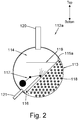
- FIG. 2 shows a cross-sectional view of a vessel 112a that acts as a condenser subassembly.
- the vessel 112a is cylindrical and has a partition 115a dividing the interior of the vessel 112a into a condenser chamber 113 and a flash tank chamber 114.
- the partition 115a extends around the flash tank chamber 114 to form a flash tank pressure envelope that is semi-circular.
- liquid duct 116 fluidly connecting the bottom of the condenser chamber 113 to the flash tank chamber 114. This is connected to a point near the bottom of the condenser chamber 113 where liquid refrigerant will collect.
- an internal float valve 117 that acts as an expansion device for the liquid from the condenser chamber 116 and controls the rate of flow of refrigerant form the condenser chamber 113 into the flash tank chamber.
- heat exchanger tubes 118 Inside of the condenser chamber 113 there is a plurality of heat exchanger tubes 118 that pass axially along the length of the chamber and which, in use, are surrounded by refrigerant, which is to be condensed.
- the heat exchanger tubes pass through the condenser chamber, the refrigerant enters from the top of the condenser chamber 113 and travels down past the heat exchanger tubes 118 through the action of gravity and under the force of the pressure/flow of refrigerant from the compressor.
- a screen 119 positioned between the liquid duct 116 and a vapour outlet 120.
- the vapour outlet is positioned towards the top of the chamber and leads to the economizer vapour line and an economizer port of the compressor as described above in relation to Figure 1b .
- the flash tank chamber also has a liquid outlet 121 positioned near its bottom that leads to an expansion device where it is expanded and subsequently enters an evaporator as described above in relation to Figure 1b .
- refrigerant passes from a compressor discharge port into the condenser chamber 113, where it is cooled via heat exchange with the plurality of heat exchanger tubes 118.
- the heat exchanger tubes can be arranged to carry any suitable coolant fluid, such as water or some other refrigerant received from a separate refrigerant circuit.
- the refrigerant in the condenser chamber 113 is cooled and condensed such that it collects towards the bottom of the condenser chamber 113.
- the float valve 117 remains open as long as the liquid level in the flash tank chamber 114 has not risen high enough to push the float of the float valve upwards.
- a closing part on the other end of a pivoting arm of the float valve 117 reduces the size of the orifice through which refrigerant can flow from the condenser chamber 113 to the flash tank chamber 114, thus reducing the flow rate.
- the float valve is arranged to control the flow rate in this way in order to match the flow rate of refrigerant leaving the flash tank chamber 114, thereby maintaining a substantially constant liquid level in the flash tank chamber 114.
- the vessel thus comprises two different pressure envelopes, the higher pressure envelope of the condenser chamber 113 and the lower pressure envelope of the flash tank chamber 114.
- the screen 119 in the flash tank chamber 114 slows the flow of refrigerant towards the vapour outlet so that it has time to expand properly in the flash tank chamber 114.
- the screen also prevents liquid refrigerant splash or spray from entering the vapour outlet 120 to ensure that the refrigerant which exits the vapour outlet 120 is only expanded vapour and not liquid, which is undesirable.
- the refrigerant in the flash tank chamber 114 then separates into liquid towards the bottom and vapour towards the top portion of the flash tank chamber 114 (the two phases are shown separated by a horizontal dashed line in the flash tank chamber 114 of Figure 2 ).
- the vapour refrigerant passes from the vapour outlet 120 of the flash tank chamber 114 along an economizer vapour line to an economizer port of the compressor.
- the liquid refrigerant passes from the liquid outlet 121 of the flash tank chamber 114 to an expansion valve 14 where it is expanded and subsequently enters an evaporator.
- FIG 3 shows a cross-sectional view of another vessel 112b that acts as a condenser subassembly.
- This vessel 112b essentially comprises the same components and operates in a similar manner to the vessel shown in Figure 2 as described above but in place of the liquid duct 116 and internal float valve 117, this vessel comprises an external expansion device 122.
- the partition 115b fully divides the interior of the vessel into the condenser chamber 113 and the flash tank chamber 114, thus sealing the two from one another.
- the external expansion device 122 is fluidly connected to a point near the bottom of the condenser chamber 113 and draws condensed liquid refrigerant out of the condenser chamber, expands it and passes it into the flash tank chamber 114 where the refrigerant separates into a liquid and vapour as previously described.
- the expansion device 122 may be an electronic expansion valve, or a fixed orifice device, such as a capillary tube, all of which operate to expand the liquid refrigerant flowing through the expansion device 122 into a mixture of liquid and vapour that is passed into the flash tank chamber 114.
- the vessel 112, 112a, 112b may be formed from a pre-existing pressure vessel that has already been approved for meeting industry standards for use with the pressure envelopes of the condenser chamber 113 (and the flash tank chamber 114).
- any of the partition 115a, 115b, liquid duct 116, screen 119 and float valve 117 or expansion device 122 may be retrofitted to such a pressure vessel.
Landscapes
- Engineering & Computer Science (AREA)
- Physics & Mathematics (AREA)
- Mechanical Engineering (AREA)
- Thermal Sciences (AREA)
- General Engineering & Computer Science (AREA)
- Cooling Or The Like Of Semiconductors Or Solid State Devices (AREA)
Abstract
Description
- The present invention relates to a condenser subassembly for providing an economizer function in a refrigeration circuit, a refrigeration circuit comprising such a condenser assembly and a method of manufacturing such a condenser subassembly.
- Refrigeration circuits comprise a compressor, a condenser (i.e. a heat rejecting heat exchanger), an expansion device, and an evaporator (i.e. a heat absorbing heat exchanger) and are used to refrigerate or heat an environment or substance. Economizer cycles are sometimes employed to increase the efficiency and capacity of the system.
- One form of an economizer cycle utilises a flash tank and operates by expanding refrigerant leaving the condenser to an intermediate pressure in the flash tank (a lower pressure than that of the refrigerant in the condenser but a higher pressure than that in the evaporator) and separating the expanded refrigerant flow.
- The vapour refrigerant is directed to the economizer port of a compressor and the liquid refrigerant is directed to the evaporator via a second, main expansion valve. The main benefit of this separation of vapour and liquid refrigerant is that it lowers the enthalpy of the liquid refrigerant remaining in the flash tank, which is subsequently expanded and enters the evaporator, thus increasing the heat transferred by the evaporator and therefore increasing the overall capacity and efficiency of the circuit. This effect of an economizer cycle is well understood in the art of refrigeration circuits.
- Alternatively, an economizer cycle may utilise an economizer heat exchanger (rather than the flash tank method described above) and operate by splitting the flow of refrigerant from the condenser into a main flow and an economizer flow, before any expansion occurs. The economizer flow can then be expanded and used to sub-cool the main flow by means of a heat exchanger before the main flow itself is expanded and enters the evaporator.
- In a first aspect, the present invention provides a condenser subassembly for providing an economizer function in a refrigeration circuit, the condenser subassembly comprising: a condenser chamber; a flash tank chamber; an expansion device; and a housing, wherein the housing defines a vessel, the vessel comprising the condenser chamber and the flash tank chamber, wherein the condenser chamber and the flash tank chamber are separated from one another by a partition in the vessel and wherein the expansion device is arranged to pass condensed refrigerant from the condenser chamber to the flash tank chamber.
- Typical prior art systems such as those described above that have a dedicated flash tank assembly use a lot of space through piping, supporting brackets and the like, and can be relatively costly to implement. By having a single housing and vessel incorporating both a condenser chamber and a flash tank chamber, as proposed in the first aspect, a single subassembly can perform both the condenser and economizer functions. The condenser chamber and flash tank chamber may therefore be referred to as integrated chambers. In this way, the amount of piping required can be reduced, space can be preserved and overall installation and manufacturing costs reduced.
- It will be appreciated that the term refrigeration circuit should be taken to include the circuit when used in a refrigerator (e.g. a liquid chiller) or a heat pump, as the cycle is the same in both instances, it is only the use of the system that is different.
- The expansion device may be an internal expansion device positioned inside of the vessel and housing. By utilising an internal expansion device, the condenser subassembly conserves additional space as no associated external piping is required. Furthermore, such an internal expansion device may be more robust as it is shielded from an outside environment.
- Alternatively, the expansion device may be an external expansion device, positioned outside of the housing. Such an external expansion device is easier to access for maintenance or for replacement.
- The expansion device may comprise a float valve, or other suitable valve type, coupled with a liquid duct from the condenser chamber to the flash tank chamber. The liquid duct may be inside or outside of the vessel and housing.
- The expansion device may be an electronic expansion valve or an orifice device, such as a capillary tube or a float valve. Any of the expansion devices described herein may operate to expand liquid refrigerant flowing through the expansion device into a mixture of liquid and vapour and pass this mixture into the flash tank chamber. In the case of an electronic expansion valve, the expansion valve may be coupled to a level sensor to measure the level of liquid in the flash tank chamber and adjust the opening of the electronic expansion valve accordingly.
- The vessel (and housing) may be substantially cylindrical. However, the skilled person will appreciate that the vessel can take any shape as long as it may be divided by the partition into the condenser chamber and flash tank chamber and the expansion device can pass liquid between these two chambers. For example, the vessel and/or housing may have a shape known for pressure vessels, such as tubular or prismatic shapes, including cylinders and including forms with or without rounded ends.
- The partition may divide the vessel into two pressure envelopes, with one pressure envelope inside of a pressure envelope of the vessel. For example, the vessel may be an outer vessel and the partition may comprise an inner vessel within the outer vessel. This inner vessel may contain the flash tank chamber or the condenser chamber. The inner vessel may be substantially cylindrical.
- Alternatively, the inner vessel may have a substantially semi-circular cross-section. The inner vessel may have a cross-section that is a partial circle, and this cross-section may resemble a circle that has a circular segment removed along a chord length.
- It will be appreciated that the vessel size and shape can be optimised for a particular set of operating conditions of the condenser subassembly.
- A portion of the outer surface of the inner vessel may be curved. Part of the outer surface of the inner vessel may have a contour that matches an inner contour of the outer vessel.
- The partition may divide the vessel at a chord length in its cross-section. The partition may extend fully or partially along the length of the vessel.
- By utilising a vessel and partition of the above arrangements, a pre-existing pressure vessel from a condenser subassembly can be repurposed for use in the subassembly of the first aspect. Such vessels, which may typically be cylindrical, are of course already suited to the pressure envelope of the condenser chamber and can have pre-existing regulatory/design approvals. This provides an easier way to add the economiser capability to an existing system rather than needing an additional fully-self-contained pressure vessel as well as potentially streamlining the design/approval process by avoiding new forms of pressure vessel. For example, by adding an inner vessel for the flash tank chamber inside of an existing vessel having pre-existing regulatory/design approvals for a condenser assembly. Such configurations also allow the relevant volumes of the vessel and respective chambers to be calculated easily.
- The partition may be reinforced or strengthened in order to withstand the pressure envelopes of the flash tank chamber and the condenser chamber. In particular, the partition may be reinforced or strengthened in order to withstand the pressure difference between the two chambers.
- The housing and/or condenser chamber may comprise an inlet that is arranged to be fluidly connected to the pressure port of a compressor and this may be via other system components such as an oil separator and/or sound muffler.
- The condenser chamber may comprise a heat exchanger arranged to cool the refrigerant in the chamber in order to condense it. The heat exchanger may comprise a plurality of heat exchanger tubes. The plurality of heat exchanger tubes may extend along the length of the condenser chamber. The plurality of heat exchanger tubes and condenser chamber may form a tube-in-shell heat exchanger arrangement. The plurality of heat exchanger tubes may be arranged to be surrounded by refrigerant that is to be condensed. However, the skilled person will appreciate that any suitable heat exchanger can be employed in order to cool and condense the refrigerant in the condenser chamber.
- The heat exchanger tubes may be arranged to receive water and/or any other suitable coolant fluid (e.g. water mixed with glycol for the prevention of freezing) in order to cool the refrigerant in the condenser chamber. The water or other suitable coolant fluid may be received from a separate refrigeration circuit.
- The expansion device may be fluidly connected to a point near the bottom of the condenser chamber, where, during use, condensed refrigerant will collect under the action of gravity. This may be the lowest point of the condenser chambers such that any condensed refrigerant can be passed to the flash tank chamber.
- The condenser chamber may extend along the full length of the vessel. The flash tank may extend along the full length of the vessel. This maximises the space utilised and thus the possible effectiveness of these components.
- Alternatively, the condenser chamber and/or flash tank chamber may extend along part of the length of the vessel. This allows the remaining space in the vessel to be reserved or other components.
- For example, an oil separator may be incorporated inside of the vessel. Thus, the vessel may comprise a condenser chamber, flash tank chamber and an oil separator. The oil separator may be in an oil separator chamber of the vessel. The oil separator may remove oil from a refrigerant flow before it enters the condenser chamber.
- Additionally, or alternatively, a sound muffler may be incorporated inside of the vessel. Thus, the vessel may comprise a condenser chamber, flash tank chamber, an oil separator and a sound muffler. The sound muffler may be in a sound muffler chamber of the vessel.
- In the case of a system employing these optional features, refrigerant flowing through the circuit from the discharge port of a compressor may pass through the sound muffler, followed by the oil separator, condenser chamber and then the flash tank chamber.
- The flash tank chamber may comprise a vapour outlet and a liquid outlet. The liquid outlet may be arranged to be fluidly connected to an evaporator via a further expansion device. The vapour outlet may be arranged to be connected to an economizer line and/or an economizer port of a compressor.
- The flash tank chamber may comprise an inlet for fluid from the condenser, which may be provided by the liquid duct mentioned above.
- The condenser subassembly may comprise a screen inside of the vessel. The screen may be positioned within the flash tank chamber. The screen may be arranged to disrupt, slow and/or steady the flow path of refrigerant to the vapour outlet and//or liquid outlet. The screen may be arranged to prevent refrigerant liquid spray from reaching the vapour outlet. This is undesirable as only vapour should exit via the vapour outlet. In some examples the screen blocks a line of sight between the vapour outlet and the inlet for fluid from the condenser.
- In a second aspect, the present invention provides a refrigeration circuit comprising: a condenser subassembly as claimed in any previous claim; a compressor; and an evaporator; wherein the condenser subassembly has a vapour outlet which is fluidly connected to an economizer port of the compressor and a liquid outlet which is fluidly connected to the evaporator via an expansion device, and wherein a discharge (i.e. pressure or exhaust) port of the compressor is fluidly connected to the condenser chamber, optionally via any of the additional intermediate components described herein .
- The condenser subassembly may be attached/fixed to the compressor, thus conserving even more space by minimising piping and supports between the two.
- The compressor may be a multi-stage compressor. The compressor may have a lower compression stage and higher compression stage and the economizer port may be positioned at an intermediate stage between the two. The economizer port of the compressor may be arranged between stages of the compressor such that it receives the vapour refrigerant from the flash tank. As a result of the separation of vapour and liquid refrigerant in the flash tank, the remaining liquid refrigerant in the flash tank (which is subsequently expanded and passed to the evaporator) has a lower enthalpy, therefore increasing the capacity and efficiency of the system as described previously.
- The vapour outlet may be fluidly connected to the economizer port of the compressor via an economizer vapour line. The economizer vapour line may comprise a flow regulating valve that is arranged to control the rate of flow of refrigerant in the economizer line.
- The flow regulating valve may be controlled by a controller. The controller may be connected to a sensor in the flash tank and/or a sensor in the compressor in order to measure conditions of the refrigerant at the flash tank and/or compressor. A sensor at the compressor may measure conditions at a mid-stage point of the compressor. The conditions may comprise temperature, pressure and/or rate of flow. The flow regulating valve may be controlled based on any of these sensed conditions.
- The evaporator may be configured to cool a gas or liquid passing over it as the refrigerant therein is heated and evaporated. The evaporator may cool a refrigerated area such as a refrigerated compartment via coolant fluid for example.
- The condenser chamber may receive refrigerant from the discharge port of the compressor (optionally via any of the additional, intermediate components described herein) and function to cool the refrigerant therein so that it condenses to a liquid.
- The refrigeration circuit may comprise an oil separator arranged to remove oil from a refrigerant flow. The oil separator may be positioned in the refrigerant circuit between the compressor discharge port and the condenser chamber to remove oil from a refrigerant flow before it enters the condenser chamber. The oil separator may be integrated into the condenser subassembly. The oil separator may be positioned within the vessel and/or housing. Oil is typically introduced into the refrigerant in the compressor but should be removed before the refrigerant is condensed to improve efficiency and avoid oil traps in the refrigeration circuit. Oil that is removed from the refrigerant by the oil separator may be returned to the compressor to be re-used. The oil may be returned to the compressor directly or via an intermediate oil tank.
- In a third aspect, the present invention provides a method of manufacturing a condenser subassembly for providing an economizer function in a refrigeration circuit, the method comprising: providing a housing, wherein the housing defines a vessel; providing a partition in the vessel; providing a condenser chamber and a flash tank chamber in the vessel, wherein the condenser chamber and the flash tank chamber are separated from one another by the partition in the vessel; and providing an expansion device, wherein the expansion device is arranged to pass condensed refrigerant from the condenser chamber to the flash tank chamber.
- The method of manufacturing a condenser subassembly may form the condenser subassembly for providing an economizer function in a refrigeration circuit according to the first aspect, including providing any of the optional features described herein.
- The vessel (or housing) may be a pre-existing pressure vessel. The pre-existing pressure vessel may be part of an existing condenser subassembly. The method may comprise retrofitting the partition to the pre-existing pressure vessel in order to form the condenser chamber and flash tank chamber. In this way, a pre-existing pressure vessel that has already been approved for meeting industry standards may be used. The vessel may be pre-approved for use with the pressure envelopes of the condenser chamber and optionally the flash tank chamber.
- The method may comprise determining a volume of the vessel that is required in order to provide a certain economizer function in a refrigeration circuit.
- The method may comprise determining a volume of the condenser chamber and/or a volume of the flash tank chamber that is required in order to provide a certain economizer function in a refrigeration circuit.
- The method may comprise designing a flash tank chamber and/or a condenser chamber to fit in an available volume. This may maximise the use of available space.
- The method may comprise determining a position and/or a required strength of the partition in the vessel in order for the partition to withstand a pressure difference between the condenser chamber and flash tank chamber when the condenser subassembly provides a certain economizer function.
- Certain example embodiments will now be described by way of example only and with reference to the accompanying drawings, in which:
-
Figure 1a shows a schematic view of a known refrigeration circuit comprising a flash tank economizer; -
Figure 1b shows a schematic view of a refrigeration circuit comprising a condenser subassembly for providing an economizer function with an integrated flash tank chamber; -
Figure 2 shows a cross-sectional view of a condenser subassembly comprising an integrated flash tank chamber and an internal expansion device; and -
Figure 3 shows a cross-sectional view of another condenser subassembly comprising an integrated flash tank chamber and an external expansion device. - With reference to
Figure 1a , there is shown aconventional refrigeration circuit 11 that includes, in serial flow relationship, acompressor 12, acondenser 13, aflow control device 19, aflash tank 21, anexpansion device 14, and anevaporator 16. - The
compressor 12, which functions to compress and circulate refrigerant through the refrigeration circuit, comprises a single, multi-stage compressor having alower compression stage 17 andhigher compression stage 18. - The
condenser 13 receives refrigerant from the discharge port of thecompressor 12 and functions to cool the refrigerant therein so that it condenses to a liquid. - The evaporator 16 functions to cool a gas or liquid passing over it as the refrigerant therein is heated and evaporated. The heated vapour then passes to an inlet of the
compressor 12. - Disposed between the
condenser 13 and theexpansion device 14 is theflow control device 19 and theflash tank 21. Theflash tank 21, together with aneconomizer vapour line 22 fluidly interconnecting theflash tank 21 to an economizer port of thecompressor 12, forms part of an economizer circuit. - In operation, the refrigerant exiting the
condenser 13 passes through theflow control device 19 where it is expanded to reduce its pressure. The resulting mixture of liquid and vapour then enters theflash tank 21, with the liquid 24 settling to the bottom portion of theflash tank 21 and thevapour 26 residing in the top portion of theflash tank 21. The liquid refrigerant 24 passes to theexpansion device 14 where it is expanded and subsequently enters theevaporator 16. - In a process known as economized operation, the
vapour 26 passes along theeconomizer vapour line 22 to an economizer port of thecompressor 12. As discussed above, a result of the separation of vapour and liquid refrigerant in theflash tank 21 is that the remaining liquid refrigerant in the flash tank 21 (which is subsequently expanded and passed to the evaporator 16) has a lower enthalpy, therefore increasing the capacity and efficiency of the system. - The
flow control device 28, which is an electronically controlled flow control device such as a solenoid valve, is controlled by acontroller 29 in response to sensed conditions at theflash tank 21 and at thecompressor 12. For example, a sensor S1 senses an operational condition at theflash tank 21, and a sensor S2 senses an operational condition at amid-stage point 27 of thecompressor 12. The sensed conditions then cause thecontroller 29 to either open theflow control device 28 to permit economized operation or to close theflow control device 28 to thereby turn off the economizer. - Now with reference to
Figure 1b , there is shown arefrigeration circuit 111 that includes avessel 112 comprising anintegrated condenser chamber 113 and an integratedflash tank chamber 114. The structure of the vessel will be described in more detail below with reference toFigures 2 and3 . - The reference numerals in
Figure 1b represent similar components as those described above in relation to the same reference numbers ofFigure 1a . - Similar to the system shown in
Figure 1a , thecompressor 12 of therefrigeration circuit 111 functions to compress and circulate refrigerant through the refrigeration circuit, and comprises a single, multi-stage compressor having alower compression stage 17 andhigher compression stage 18. - The
vessel 112 receives refrigerant from the discharge port of thecompressor 12 and this refrigerant enters thecondenser chamber 113 of the vessel first, which functions to cool the refrigerant therein so that it condenses to a liquid. - An expansion device (not shown) inside of the vessel is arranged to pass condensed refrigerant from the
condenser chamber 113 to theflash tank chamber 114. - The expansion device and
flash tank chamber 114, together with aneconomizer vapour line 22 fluidly interconnecting a vapour outlet of theflash tank chamber 114 to an economizer port of thecompressor 12, form part of an economizer circuit. - In operation, the refrigerant exiting the
condenser chamber 113 passes through the expansion device where it is expanded to thereby reduce its pressure. The resulting mixture of liquid and vapour is passed into theflash tank chamber 114, with liquid settling to a bottom portion and the vapour residing in a top portion of the flash tank chamber (the dashed line within theflash tank chamber 114 schematically representing the limit between the liquid and vapour). - The vapour refrigerant passes from a vapour outlet of the
flash tank chamber 114 along theeconomizer vapour line 22 to an economizer port of thecompressor 12. As discussed above, a result of the separation of vapour and liquid refrigerant in theflash tank chamber 114 is that the remaining liquid refrigerant in the flash tank chamber 114 (which is subsequently expanded and passed to the evaporator) has a lower enthalpy, therefore increasing the capacity and efficiency of the system. - The liquid refrigerant passes from a liquid outlet of the
flash tank chamber 114 to anexpansion device 14 where it is expanded and subsequently enters anevaporator 16. Again, the evaporator 16 functions to cool a gas or liquid passing over it as the refrigerant therein is heated and evaporated. The heated vapour then passes to an inlet (suction port) of thecompressor 12. - Similar to the previously described system, a
flow control device 28, which is an electronically controlled flow control device such as a solenoid valve, is controlled by acontroller 29 in response to sensed conditions at theflash tank chamber 114 and at thecompressor 12. For example, a sensor S1 senses an operational condition at theflash tank chamber 114, and a sensor S2 senses an operational condition at amid-stage point 27 of thecompressor 12. The sensed conditions then cause thecontroller 29 to either open theflow control device 28 to permit economized operation or to close theflow control device 28 to thereby turn off the economizer. The controller can also control the rate of flow of refrigerant through theflow control device 28. - Possible structures structure of the
vessel 112 will now be described in more detail with reference toFigures 2 and3 . -
Figure 2 shows a cross-sectional view of avessel 112a that acts as a condenser subassembly. Thevessel 112a is cylindrical and has apartition 115a dividing the interior of thevessel 112a into acondenser chamber 113 and aflash tank chamber 114. Thepartition 115a extends around theflash tank chamber 114 to form a flash tank pressure envelope that is semi-circular. - There is a
liquid duct 116 fluidly connecting the bottom of thecondenser chamber 113 to theflash tank chamber 114. This is connected to a point near the bottom of thecondenser chamber 113 where liquid refrigerant will collect. - Coupled to the
liquid duct 116 is aninternal float valve 117 that acts as an expansion device for the liquid from thecondenser chamber 116 and controls the rate of flow of refrigerant form thecondenser chamber 113 into the flash tank chamber. - Inside of the
condenser chamber 113 there is a plurality ofheat exchanger tubes 118 that pass axially along the length of the chamber and which, in use, are surrounded by refrigerant, which is to be condensed. The heat exchanger tubes pass through the condenser chamber, the refrigerant enters from the top of thecondenser chamber 113 and travels down past theheat exchanger tubes 118 through the action of gravity and under the force of the pressure/flow of refrigerant from the compressor. - In the flash tank chamber there is a
screen 119 positioned between theliquid duct 116 and avapour outlet 120. The vapour outlet is positioned towards the top of the chamber and leads to the economizer vapour line and an economizer port of the compressor as described above in relation toFigure 1b . - The flash tank chamber also has a
liquid outlet 121 positioned near its bottom that leads to an expansion device where it is expanded and subsequently enters an evaporator as described above in relation toFigure 1b . - In operation, refrigerant passes from a compressor discharge port into the
condenser chamber 113, where it is cooled via heat exchange with the plurality ofheat exchanger tubes 118. The heat exchanger tubes can be arranged to carry any suitable coolant fluid, such as water or some other refrigerant received from a separate refrigerant circuit. - The refrigerant in the
condenser chamber 113 is cooled and condensed such that it collects towards the bottom of thecondenser chamber 113. Thefloat valve 117 remains open as long as the liquid level in theflash tank chamber 114 has not risen high enough to push the float of the float valve upwards. When the float is pushed upwards by a rising liquid level in theflash tank chamber 114, a closing part on the other end of a pivoting arm of thefloat valve 117 reduces the size of the orifice through which refrigerant can flow from thecondenser chamber 113 to theflash tank chamber 114, thus reducing the flow rate. The float valve is arranged to control the flow rate in this way in order to match the flow rate of refrigerant leaving theflash tank chamber 114, thereby maintaining a substantially constant liquid level in theflash tank chamber 114. - The vessel thus comprises two different pressure envelopes, the higher pressure envelope of the
condenser chamber 113 and the lower pressure envelope of theflash tank chamber 114. - The
screen 119 in theflash tank chamber 114 slows the flow of refrigerant towards the vapour outlet so that it has time to expand properly in theflash tank chamber 114. The screen also prevents liquid refrigerant splash or spray from entering thevapour outlet 120 to ensure that the refrigerant which exits thevapour outlet 120 is only expanded vapour and not liquid, which is undesirable. - The refrigerant in the
flash tank chamber 114 then separates into liquid towards the bottom and vapour towards the top portion of the flash tank chamber 114 (the two phases are shown separated by a horizontal dashed line in theflash tank chamber 114 ofFigure 2 ). - As discussed above in relation to
Figure 1b , the vapour refrigerant passes from thevapour outlet 120 of theflash tank chamber 114 along an economizer vapour line to an economizer port of the compressor. The liquid refrigerant passes from theliquid outlet 121 of theflash tank chamber 114 to anexpansion valve 14 where it is expanded and subsequently enters an evaporator. -
Figure 3 shows a cross-sectional view of anothervessel 112b that acts as a condenser subassembly. Thisvessel 112b essentially comprises the same components and operates in a similar manner to the vessel shown inFigure 2 as described above but in place of theliquid duct 116 andinternal float valve 117, this vessel comprises anexternal expansion device 122. As theliquid duct 116 is no longer required, thepartition 115b fully divides the interior of the vessel into thecondenser chamber 113 and theflash tank chamber 114, thus sealing the two from one another. - The
external expansion device 122 is fluidly connected to a point near the bottom of thecondenser chamber 113 and draws condensed liquid refrigerant out of the condenser chamber, expands it and passes it into theflash tank chamber 114 where the refrigerant separates into a liquid and vapour as previously described. - The
expansion device 122 may be an electronic expansion valve, or a fixed orifice device, such as a capillary tube, all of which operate to expand the liquid refrigerant flowing through theexpansion device 122 into a mixture of liquid and vapour that is passed into theflash tank chamber 114. - It is worth noting that in any of the embodiments described above, the
vessel partition liquid duct 116,screen 119 andfloat valve 117 orexpansion device 122 may be retrofitted to such a pressure vessel.
Claims (15)
- A condenser subassembly for providing an economizer function in a refrigeration circuit, the condenser subassembly comprising:a condenser chamber;a flash tank chamber;an expansion device; anda housing, wherein the housing defines a vessel, the vessel comprising the condenser chamber and the flash tank chamber, wherein the condenser chamber and the flash tank chamber are separated from one another by a partition in the vessel and wherein the expansion device is arranged to pass condensed refrigerant from the condenser chamber to the flash tank chamber.
- A condenser subassembly as claimed in claim 1, wherein the expansion device is an internal expansion device positioned inside of the vessel.
- A condenser subassembly as claimed in claim 1 or 2, wherein the expansion device is a float valve coupled with a liquid duct from the condenser chamber to the flash tank chamber.
- A condenser subassembly as claimed in claim 1, wherein the expansion device is an external expansion device positioned outside of the vessel.
- A condenser subassembly as claimed in any preceding claim, wherein the vessel is substantially cylindrical and the partition divides the vessel at a chord length in its cross-section along the length of the vessel or wherein the vessel is an outer vessel and the partition forms an inner vessel including a pressure envelope for the flash tank chamber inside of a pressure envelope of the outer vessel.
- A condenser subassembly as claimed in any preceding claim, wherein the condenser chamber comprises a heat exchanger for cooling a refrigerant flow through the condenser, wherein the heat exchanger preferably comprises a plurality of tubes passing through the chamber, wherein the plurality of tubes are preferably arranged to be surrounded by the refrigerant flow.
- A condenser subassembly as claimed in any preceding claim, wherein the expansion device is fluidly connected to a point near the bottom of the condenser chamber, where during use, condensed refrigerant will collect under the action of gravity.
- A condenser subassembly as claimed in any preceding claim, wherein the condenser chamber extends along the full length of the vessel and wherein the flash tank extends along at least part of the length of the vessel.
- A condenser subassembly as claimed in any preceding claim, wherein the flash tank chamber comprises a vapour outlet and a liquid outlet, wherein the vapour outlet is arranged to be fluidly connected to an economizer circuit.
- A refrigeration circuit comprising:a condenser subassembly as claimed in any previous claim;a compressor; andan evaporator; whereinthe condenser subassembly has a vapour outlet which is fluidly connected to an economizer port of the compressor and a liquid outlet which is fluidly connected to the evaporator via a main expansion device , and wherein a discharge port of the compressor is fluidly connected to the condenser chamber.
- A refrigeration circuit as claimed in claim 10, further comprising an oil separator arranged to remove oil from a refrigerant flow and/or a sound muffler, wherein the oil separator and/or sound muffler is integrated into the condenser subassembly and positioned within the housing, preferably inside of the vessel.
- A method of manufacturing a condenser subassembly for providing an economizer function in a refrigeration circuit, the method comprising:providing a housing, wherein the housing defines a vessel;providing a partition in the vessel;providing a condenser chamber and a flash tank chamber in the vessel, wherein the condenser chamber and the flash tank chamber are separated from one another by the partition in the vessel; andproviding an expansion device, wherein the expansion device is arranged to pass condensed refrigerant from the condenser chamber to the flash tank chamber.
- A method of manufacturing a condenser subassembly as claimed in claim 12, wherein the housing is a pre-existing pressure vessel, and the method comprises retrofitting the partition to the pre-existing pressure vessel in order to form the condenser chamber and a flash tank chamber.
- A method of manufacturing a condenser subassembly as claimed in claim 12 or 13, the method comprising: determining a volume of the vessel, a volume of the condenser chamber and a volume of the flash tank chamber that is required in order to provide a certain economizer function in a refrigeration circuit.
- A method of manufacturing a condenser subassembly as claimed in any one of claims 12 to 14, the method comprising: determining a position and a required strength of the partition in the vessel in order for the partition to withstand a pressure difference between the condenser chamber and flash tank chamber when the condenser subassembly provides a certain economizer function.
Priority Applications (3)
| Application Number | Priority Date | Filing Date | Title |
|---|---|---|---|
| EP20173152.8A EP3907445A1 (en) | 2020-05-06 | 2020-05-06 | Condenser subassembly with integrated flash tank |
| CN202011501097.6A CN113623879B (en) | 2020-05-06 | 2020-12-18 | Condenser subassembly with integrated flash tank |
| US17/133,866 US12264856B2 (en) | 2020-05-06 | 2020-12-24 | Condenser subassembly with integrated flash tank |
Applications Claiming Priority (1)
| Application Number | Priority Date | Filing Date | Title |
|---|---|---|---|
| EP20173152.8A EP3907445A1 (en) | 2020-05-06 | 2020-05-06 | Condenser subassembly with integrated flash tank |
Publications (1)
| Publication Number | Publication Date |
|---|---|
| EP3907445A1 true EP3907445A1 (en) | 2021-11-10 |
Family
ID=70553990
Family Applications (1)
| Application Number | Title | Priority Date | Filing Date |
|---|---|---|---|
| EP20173152.8A Pending EP3907445A1 (en) | 2020-05-06 | 2020-05-06 | Condenser subassembly with integrated flash tank |
Country Status (3)
| Country | Link |
|---|---|
| US (1) | US12264856B2 (en) |
| EP (1) | EP3907445A1 (en) |
| CN (1) | CN113623879B (en) |
Families Citing this family (5)
| Publication number | Priority date | Publication date | Assignee | Title |
|---|---|---|---|---|
| CN114165446A (en) * | 2021-12-14 | 2022-03-11 | 珠海格力电器股份有限公司 | Multistage compressors and air conditioning units |
| CN115342544B (en) * | 2022-08-11 | 2024-10-18 | 青岛海尔空调电子有限公司 | Economizer and air conditioner refrigerating system |
| US12313072B2 (en) | 2022-11-30 | 2025-05-27 | Trane International Inc. | Oil-free phase separating compressor |
| CN116907128B (en) * | 2023-08-25 | 2025-10-17 | 珠海格力电器股份有限公司 | Condenser and refrigeration system |
| FR3162505A1 (en) * | 2024-05-25 | 2025-11-28 | Valeo Systemes Thermiques | Method for controlling a thermal conditioning system |
Citations (3)
| Publication number | Priority date | Publication date | Assignee | Title |
|---|---|---|---|---|
| JPS504344U (en) * | 1973-05-09 | 1975-01-17 | ||
| JPS53157462U (en) * | 1977-05-18 | 1978-12-09 | ||
| CN203964469U (en) * | 2014-04-25 | 2014-11-26 | 重庆美的通用制冷设备有限公司 | Shell and tube exchanger and the handpiece Water Chilling Units with it |
Family Cites Families (6)
| Publication number | Priority date | Publication date | Assignee | Title |
|---|---|---|---|---|
| US2277647A (en) * | 1940-08-01 | 1942-03-24 | Carrier Corp | Refrigeration |
| US2888809A (en) * | 1955-01-27 | 1959-06-02 | Carrier Corp | Gas compression apparatus |
| US4332642A (en) * | 1981-06-19 | 1982-06-01 | Westinghouse Electric Corp. | Paired stage flash evaporator having improved distillate collection |
| US4437322A (en) * | 1982-05-03 | 1984-03-20 | Carrier Corporation | Heat exchanger assembly for a refrigeration system |
| CA2596361A1 (en) * | 2005-02-02 | 2006-08-10 | Carrier Corporation | Refrigerating system with economizing cycle |
| JP6607558B2 (en) * | 2015-08-31 | 2019-11-20 | 三菱重工サーマルシステムズ株式会社 | Refrigerator and control method thereof |
-
2020
- 2020-05-06 EP EP20173152.8A patent/EP3907445A1/en active Pending
- 2020-12-18 CN CN202011501097.6A patent/CN113623879B/en active Active
- 2020-12-24 US US17/133,866 patent/US12264856B2/en active Active
Patent Citations (3)
| Publication number | Priority date | Publication date | Assignee | Title |
|---|---|---|---|---|
| JPS504344U (en) * | 1973-05-09 | 1975-01-17 | ||
| JPS53157462U (en) * | 1977-05-18 | 1978-12-09 | ||
| CN203964469U (en) * | 2014-04-25 | 2014-11-26 | 重庆美的通用制冷设备有限公司 | Shell and tube exchanger and the handpiece Water Chilling Units with it |
Also Published As
| Publication number | Publication date |
|---|---|
| CN113623879B (en) | 2025-06-06 |
| CN113623879A (en) | 2021-11-09 |
| US20210348809A1 (en) | 2021-11-11 |
| US12264856B2 (en) | 2025-04-01 |
Similar Documents
| Publication | Publication Date | Title |
|---|---|---|
| US12264856B2 (en) | Condenser subassembly with integrated flash tank | |
| JP4404148B2 (en) | Economizer | |
| US1836318A (en) | Refrigerating system | |
| KR100236574B1 (en) | Dual Inlet Oil Separator for Chiller | |
| TW201807367A (en) | Gas discharge apparatus, refrigerating and air-conditioning unit, and method of discharging non-condensable gas | |
| US3481151A (en) | Refrigerant system employing liquid chilling evaporators | |
| JP6607558B2 (en) | Refrigerator and control method thereof | |
| KR101220741B1 (en) | Freezing device | |
| CN106440593B (en) | Frequency converter cooling system, air conditioning unit and control method | |
| US11365920B2 (en) | Heat exchanger with refrigerant storage volume | |
| US6018958A (en) | Dry suction industrial ammonia refrigeration system | |
| JP2015190733A (en) | Evaporator of turbo refrigerator, and turbo refrigerator including evaporator | |
| KR20150133565A (en) | Economizer comprising condenser and turbo chiller comprising the same | |
| CN114508878B (en) | Separator and refrigeration unit fluid conditioning device | |
| FI92432C (en) | Compression cooling system with oil separator | |
| CN114165446A (en) | Multistage compressors and air conditioning units | |
| JP2003028523A (en) | Refrigeration equipment and oil tank integrated accumulator | |
| US6425262B1 (en) | Motor vehicle air conditioning circuit provided with pre-expansion device | |
| CN218915481U (en) | Flash evaporator, air supplementing and enthalpy increasing system and air conditioning equipment | |
| KR100624025B1 (en) | Accumulator for Air Conditioning System | |
| CN220689430U (en) | Flash tank and multi-split heat pump air conditioning system | |
| CN119617710B (en) | Horizontal oil separator, separation method and refrigeration system | |
| CN222504308U (en) | Heat exchanger and air conditioning system | |
| JP2007285591A (en) | Refrigerating cycle device | |
| KR100784612B1 (en) | Expansion valve of cooling system and gas-liquid separator with internal heat exchanger |
Legal Events
| Date | Code | Title | Description |
|---|---|---|---|
| PUAI | Public reference made under article 153(3) epc to a published international application that has entered the european phase |
Free format text: ORIGINAL CODE: 0009012 |
|
| STAA | Information on the status of an ep patent application or granted ep patent |
Free format text: STATUS: THE APPLICATION HAS BEEN PUBLISHED |
|
| AK | Designated contracting states |
Kind code of ref document: A1 Designated state(s): AL AT BE BG CH CY CZ DE DK EE ES FI FR GB GR HR HU IE IS IT LI LT LU LV MC MK MT NL NO PL PT RO RS SE SI SK SM TR |
|
| B565 | Issuance of search results under rule 164(2) epc |
Effective date: 20201012 |
|
| STAA | Information on the status of an ep patent application or granted ep patent |
Free format text: STATUS: REQUEST FOR EXAMINATION WAS MADE |
|
| 17P | Request for examination filed |
Effective date: 20220510 |
|
| RBV | Designated contracting states (corrected) |
Designated state(s): AL AT BE BG CH CY CZ DE DK EE ES FI FR GB GR HR HU IE IS IT LI LT LU LV MC MK MT NL NO PL PT RO RS SE SI SK SM TR |
|
| STAA | Information on the status of an ep patent application or granted ep patent |
Free format text: STATUS: EXAMINATION IS IN PROGRESS |
|
| 17Q | First examination report despatched |
Effective date: 20230224 |
|
| GRAP | Despatch of communication of intention to grant a patent |
Free format text: ORIGINAL CODE: EPIDOSNIGR1 |
|
| STAA | Information on the status of an ep patent application or granted ep patent |
Free format text: STATUS: GRANT OF PATENT IS INTENDED |
|
| INTG | Intention to grant announced |
Effective date: 20260204 |