EP3907122A1 - Lenkschaltgetriebe für kettenfahrzeuge als parallelhybrid - Google Patents
Lenkschaltgetriebe für kettenfahrzeuge als parallelhybrid Download PDFInfo
- Publication number
- EP3907122A1 EP3907122A1 EP21151383.3A EP21151383A EP3907122A1 EP 3907122 A1 EP3907122 A1 EP 3907122A1 EP 21151383 A EP21151383 A EP 21151383A EP 3907122 A1 EP3907122 A1 EP 3907122A1
- Authority
- EP
- European Patent Office
- Prior art keywords
- drive shaft
- motor
- drive
- switching element
- shaft
- Prior art date
- Legal status (The legal status is an assumption and is not a legal conclusion. Google has not performed a legal analysis and makes no representation as to the accuracy of the status listed.)
- Granted
Links
Images






Classifications
-
- B—PERFORMING OPERATIONS; TRANSPORTING
- B62—LAND VEHICLES FOR TRAVELLING OTHERWISE THAN ON RAILS
- B62D—MOTOR VEHICLES; TRAILERS
- B62D11/00—Steering non-deflectable wheels; Steering endless tracks or the like
- B62D11/02—Steering non-deflectable wheels; Steering endless tracks or the like by differentially driving ground-engaging elements on opposite vehicle sides
- B62D11/06—Steering non-deflectable wheels; Steering endless tracks or the like by differentially driving ground-engaging elements on opposite vehicle sides by means of a single main power source
- B62D11/10—Steering non-deflectable wheels; Steering endless tracks or the like by differentially driving ground-engaging elements on opposite vehicle sides by means of a single main power source using gearings with differential power outputs on opposite sides, e.g. twin-differential or epicyclic gears
- B62D11/14—Steering non-deflectable wheels; Steering endless tracks or the like by differentially driving ground-engaging elements on opposite vehicle sides by means of a single main power source using gearings with differential power outputs on opposite sides, e.g. twin-differential or epicyclic gears differential power outputs being effected by additional power supply to one side, e.g. power originating from secondary power source
-
- B—PERFORMING OPERATIONS; TRANSPORTING
- B62—LAND VEHICLES FOR TRAVELLING OTHERWISE THAN ON RAILS
- B62D—MOTOR VEHICLES; TRAILERS
- B62D11/00—Steering non-deflectable wheels; Steering endless tracks or the like
- B62D11/02—Steering non-deflectable wheels; Steering endless tracks or the like by differentially driving ground-engaging elements on opposite vehicle sides
- B62D11/04—Steering non-deflectable wheels; Steering endless tracks or the like by differentially driving ground-engaging elements on opposite vehicle sides by means of separate power sources
-
- B—PERFORMING OPERATIONS; TRANSPORTING
- B62—LAND VEHICLES FOR TRAVELLING OTHERWISE THAN ON RAILS
- B62D—MOTOR VEHICLES; TRAILERS
- B62D11/00—Steering non-deflectable wheels; Steering endless tracks or the like
- B62D11/02—Steering non-deflectable wheels; Steering endless tracks or the like by differentially driving ground-engaging elements on opposite vehicle sides
- B62D11/06—Steering non-deflectable wheels; Steering endless tracks or the like by differentially driving ground-engaging elements on opposite vehicle sides by means of a single main power source
Definitions
- the invention relates to an arrangement according to the preamble of claim 1.
- Conventional tracked vehicles have a superimposed steering gear. This is based on two planetary gears, each of which drives a chain drive. A drive motor acts on both planetary gears via a rigid shaft. Furthermore, the planetary gears are coupled with a counter-rotating gear, via which a steering torque is applied. A hydraulic motor is used to drive the steering, to which the counter-rotating gear is coupled and fed by the drive motor via a hydraulic pump.
- the pamphlet DE 10 2013 204 672 A1 discloses a drive arrangement for a tracked vehicle.
- a summing gear is provided to drive the chain drives.
- the drive assembly includes three motors - an electric traction motor, an electric steering motor and an electric assist motor.
- Mechanical drive elements are provided for transmitting reactive power between a right chain drive and a left chain drive.
- the assistance motor can be switched so that it can either assist the drive motor or the steering motor.
- the invention is based on the object of making available an improved drive train for a tracked vehicle. This object is achieved by an arrangement according to claim 1. Preferred developments are contained in the subclaims and result from the following description and the exemplary embodiments shown in the figures.
- the arrangement according to the invention comprises at least two summing gears. These include a first summing gear and a second summing gear.
- a summing gearbox is a gearbox with a gearbox degree of freedom of 2.
- gear degree of freedom also known as the gear running rate
- the degree of freedom of a gearbox corresponds to the number of relative movements that must be specified so that the movements of all links of the gearbox are completely determined. This corresponds to the number of relative movements that are to be prevented in order to make all links of the transmission unable to move.
- a first speed of any of the three shafts and a second speed of any other of the three shafts can be freely selected. Depending on the first speed and the second speed, the speed of the remaining of the three shafts is clearly determined.
- a gearbox that connects three shafts with a gearbox degree of freedom of 2 is called a summing gearbox if it combines two powers applied to one of the shafts into a third power applied to a third of the shafts.
- a transmission that connects three shafts with a degree of freedom of 2 is called a transfer gear or differential if it distributes power applied to one of the shafts to the other two shafts.
- transfer case and summing gear result from the intended application and are interchangeable depending on the application.
- the terms transfer gear and summing gear can be replaced by the term gear with a gear degree of freedom of 2.
- the arrangement has at least two output shafts.
- the at least two output shafts include a first output shaft and a second output shaft.
- the output shafts are shafts via which an output torque is provided in each case.
- the output shafts can each be connected to a driven wheel of a vehicle in a rotationally effective or rotationally fixed manner.
- the arrangement has at least two switching elements.
- the at least two switching elements include a first switching element and a second switching element.
- a switching element is an actuator that can be converted from an open state to a closed state and from the closed state to the open state by applying a signal, the switching element in the closed state connecting two members to one another which can be rotated relative to one another when the switching element is in the open state.
- the at least two switching elements of the arrangement are preferably clutches. These are characterized in that the two members, which can be connected to one another in a rotationally fixed manner, can be rotated relative to a non-rotatable reference system, for example to a housing. This implies that the links are waves.
- the arrangement comprises at least five drive shafts and a transfer case.
- the at least five drive shafts include a first drive shaft, a second drive shaft, a third drive shaft, a fourth drive shaft and a fifth drive shaft.
- Drive shafts are shafts to which a drive torque can be applied.
- the first drive shaft, the second drive shaft and the third drive shaft are connected to one another by means of the transfer case.
- the transfer case thus connects the first drive shaft, the second drive shaft and the third drive shaft with a gear degree of freedom of 2.
- the second drive shaft and the third drive shaft can be connected to one another in a rotationally fixed manner by means of the first switching element.
- the fourth drive shaft and the fifth drive shaft can be connected to one another in a rotationally fixed manner by means of the second switching element.
- the first summing gear connects the second drive shaft, the fourth drive shaft and the first output shaft to one another.
- the second drive shaft, the fourth drive shaft and the first output shaft are therefore connected by the first summing gear with a gear degree of freedom of 2.
- the third drive shaft, the fifth drive shaft and the second output shaft are connected to one another by means of the second summing gear.
- the second summing gear thus connects the third drive shaft, the fifth drive shaft and the second output shaft with a gear degree of freedom of 2.
- a transmission ratio between the fourth drive shaft and the first drive shaft when the second drive shaft is stationary and a transmission ratio between the fifth drive shaft and the second output shaft when the third drive shaft is stationary have opposite signs. So one gear ratio is negative while the other is positive. In addition, the two transmission ratios are preferably of the same magnitude.
- a transmission ratio between the second drive shaft and the first output shaft when the fourth drive shaft is stationary and a transmission ratio between the third drive shaft and the second output shaft when the fifth drive shaft is stationary preferably have the same sign.
- the gear ratios are either both positive or both negative.
- the two transmission ratios are preferably the same.
- a standing wave denotes a shaft that is stationary relative to the non-rotatable reference system, that is, does not rotate.
- the reference object can in particular be a transmission housing.
- the arrangement enables the integration of five motors. These include a first motor, a second motor, a third motor, a fourth motor and a fifth motor.
- the first motor is connected or can be connected to the first drive shaft in a rotationally effective manner.
- the rotationally effective connection exists in detail between the shaft and a rotor or a crankshaft of the engine.
- a rotationally effective connection between a motor and a shaft denotes a connection with a gear degree of freedom of 1, also known as a positive connection.
- the connection can be designed to be non-rotatable or in such a way that there is a linear speed relationship between the motor and the shaft.
- the second motor is rotatably connected or connectable to the second drive shaft, the third motor to the third drive shaft, the fourth motor to the fourth drive shaft and the fifth motor to the fifth drive shaft.
- the first motor is preferably an internal combustion engine.
- the second motor, the third motor, the fourth motor and the fifth motor are preferably designed as electric motors. This results in a hybrid system that can be operated particularly energy-efficiently and is also independent of the state of charge of electrical energy storage devices.
- the arrangement is preferably developed with a transmission.
- the first motor is connected or can be connected to the first drive shaft in a rotationally effective manner via the transmission.
- the motor is rotationally connected to an input shaft of the transmission and, on the other hand, an output shaft of the transmission is rotationally connected to the drive shaft.
- the transmission is preferably a manual transmission. This allows different ratios to be switched between its input shaft and its output shaft.
- the arrangement is preferably developed with a third switching element.
- the first drive shaft can be blocked by means of the third switching element.
- the third Switching element expands the number of possible drive states that can be implemented by means of the arrangement.
- a shaft can be blocked by means of a switching element, the shaft is blocked when the switching element is in the closed state.
- the switching element then establishes a non-rotatable connection between the shaft and a non-rotatable component, i.e. a component which is non-rotatable with respect to the non-rotatable reference system. Accordingly, the switching element is a brake.
- a fourth and a fifth switching element are provided in a further preferred development in order to block the first output shaft and the second output shaft.
- the first output shaft can be blocked by means of the fourth shift element, the second output shaft by means of the fifth shift element.
- the fourth switching element and the fifth switching element also increase the number of drive states that can be implemented by means of the arrangement.
- a service or parking brake of the vehicle is preferably used as the fourth and fifth switching element.
- the output shafts are each connected in a rotationally effective manner to a chain running gear, so that a chain running gear is driven via the two drive shafts.
- the driven wheels are therefore each driven wheel of a chain drive.
- the track drives are arranged on opposite sides of a tracked vehicle. So you are on different sides of a sagittal plane of the vehicle. This is a plane that runs through the center of the vehicle and is oriented vertically.
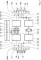
- the arrangement shown comprises a first summing gear SUM1, a second summing gear SUM2, a first output shaft AB1, a second output shaft AB2, a first shift element S1, a second shift element S2, a third shift element S3, a fourth shift element S4, a fifth shift element S5, a first Drive shaft AN1, a second drive shaft AN2, a third drive shaft AN3, a fourth drive shaft AN4, a fifth drive shaft AN5, a transfer case VER, a first motor M1, a second motor M2, a third motor M3, a fourth motor M4, a fifth motor M5 and a manual transmission G.
- the motor M1 is preferably designed as an internal combustion engine. It is connected to the transfer case VER via the gearbox G. An output shaft of the motor M1 and an input shaft of the manual transmission G are identical. Furthermore, an output shaft of the gearbox G and an input shaft of the transfer case VER are identical. This is the first drive shaft AN1.
- the first drive shaft AN1, the second drive shaft AN2 and the third drive shaft AN3 are connected to one another via the transfer case VER.
- the transfer case VER can be locked via the switching element S1. This means that a non-rotatable connection between the second drive shaft AN2 and the third drive shaft AN3 comes about when the first switching element S1 is closed.
- the second switching element S2 acts between the fourth drive shaft AN4 and the fifth drive shaft AN5.
- the second shift element S2 is a clutch which is designed to connect the fourth drive shaft AN4 and the fifth drive shaft AN5 to one another in a rotationally fixed manner in the closed state. If the switching element S2 is open, the two shafts AN4, AN5 can be freely rotated relative to one another.
- the third switching element S3 is designed as a brake and acts on the first drive shaft AN1.
- the switching element S3 by means of the switching element S3, the first drive shaft AN1 can be braked and kept fixed to the housing.
- the second motor M2, the third motor M3, the fourth motor M4 and the fifth motor M5 are designed as electric motors. Your rotor is connected to a drive shaft AN2, AN3, AN4, AN5 in a rotationally fixed manner. Specifically, there are non-rotatable connections between the second drive shaft AN2 and the rotor of the second motor M2, between the third drive shaft AN3 and the rotor of the third motor M3, between the fourth drive shaft AN4 and the rotor of the fourth motor M4 and between the fifth drive shaft AN5 and the rotor of the fifth motor M5.
- the drive shafts AN2, AN3, AN4, AN5 each have a pinion R1, R2, R3, R4.
- the second drive shaft AN2 is rotatably connected to a first pinion R1.
- the third drive shaft AN3 is non-rotatably connected to a second pinion R2, the fourth drive shaft AN4 to a third pinion R3 and the fifth drive shaft AN5 to a fourth pinion R4.
- the first pinion R1 and the third pinion R3 are part of the first summing gear SUM1.
- the second pinion R2 and the fourth pinion R4 are part of the second summing gear SUM2.
- the first summing gear SUM1 also includes a first planetary stage PL1, a first intermediate gear Z1 and a second intermediate gear Z2.
- the second summing gear SUM2 comprises a second planetary stage PL2, a third intermediate gear Z3 and a fourth intermediate gear Z4.
- the first intermediate gear Z1 is non-rotatably connected to a ring gear of the first planetary stage PL1. It meshes with the first sprocket R2.
- the third intermediate gear Z3 is non-rotatably connected to a ring gear of the second planetary stage PL2 and meshes with the second pinion R2.
- the second intermediate gear Z2 is non-rotatably connected to a sun gear of the first planetary stage PL1.
- the third pinion R3 meshes with the second intermediate gear Z2.
- the fourth intermediate gear Z4 is non-rotatably connected to a sun gear of the second planetary stage PL2.
- the fourth intermediate gear Z4 does not mesh with the fourth pinion R4. Instead, a fifth intermediate gear Z5 is provided between the fourth intermediate gear Z4 and the fourth pinion R4, which meshes with the fourth intermediate gear Z4 and the fourth pinion R4. This results in a reversal of the direction of rotation. Rotate the fourth motor M4 and the fifth motor M5 in the same direction, the second Intermediate gear Z2 and the fourth intermediate gear Z4 are driven in opposite directions, that is, driven in different directions.
- the planet carriers of the two planetary stages PL1, PL2 are non-rotatably connected to the output shafts AB1, AB2. Specifically, the planet carrier of the first planetary stage PL1 is non-rotatably connected to the first output shaft AB1, and the planet carrier of the second planetary stage PL2 is connected to the second output shaft AB2.
- the output shafts Ab1, AB2 are rotatably connected to a drive wheel of a chain drive.
- the in Fig. 1 The operating state shown corresponds to straight-ahead travel or long cornering using the motor M1.
- the third switching element S3 is open and thus permeable to a drive torque of the motor M1.
- the drive torque is divided between the second drive shaft AN2 and the third drive shaft AN3 via the transfer case VER.
- the first switching element S1 is closed. This avoids speed differences between the second drive shaft AN2 and the third drive shaft AN3.
- the second element S2 is closed.
- a support torque acts between the sun gear of the first planetary stage PL1 and the sun gear of the second planetary stage PL2.
- the electric motors M2, M3, M4, M5 run without torque when driving straight ahead.
- the arrangement can be operated in a hybrid or generator mode when driving straight ahead.
- at least one of the electric motors M2, M3, M4, M5 is active and applies a drive torque to the respective drive shaft AN2, AN3, AN4, AN5.
- the electric motors M2, M3, M4, M5 can be operated as a generator for energy recuperation.
- the in Fig. 1 The operating state shown can also be used to drive curves with a wide radius.
- the fourth motor M4 and the fifth motor M5 are activated.
- the direction of the curve is dependent on the direction of rotation of the two motors M4, M5.
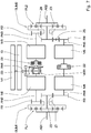
- FIG. 2 shows A corresponding operating state. This state is different from that in Fig. 1 operating state shown in that a fourth switching element S4 and a fifth switching element S5 are closed, while the second switching element S2 is open.
- the fourth shift element S4 and the fifth shift element S5 are service and parking brakes.
- the fourth shift element S4 acts on the first output shaft AB1
- the fifth shift element acts on the second output shaft AB2.
- the closed switching elements S4, S5 prevent the vehicle from starting to move due to the drive torque applied by the motor M1. Instead, the drive torque is used to drive the electric motors M2, M3, M4, M5. These act as generators and convert the drive energy introduced by the motor M1 into electrical energy.
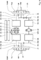
- Fig. 1 The operation of the electric motors M4, M5 for cornering according to Fig. 1 requires that a charged energy storage device is available. If the energy store is empty or if its remaining charge is to be used for some other purpose, cornering can be implemented by operating the two other electric motors M2, M3 in generator mode. A corresponding operating state is in Fig. 3 shown.
- the in Fig. 3 The operating state shown differs from that in Fig. 1 operating state shown in that the first switching element S1 is open. Since the second motor M2 or the third motor M3 are operated as a generator, a braking torque acts on the second drive shaft AN2 or the third drive shaft AN3. This results in speed differences between the two drive shafts AN2, AN3, which cause cornering.
- Fig. 4 shows an example of a closed fourth switching element S4.
- the fifth switching element S5 is open.
- the first switching element S1, the second switching element S2 and the third switching element S3 are also open.
- the drive torque of the motor M1 flows completely into the second output shaft AB2, so that the vehicle turns around the chain of the chain drive of the first output shaft AB1.
- the first switching element S1, the second switching element S2 and the third switching element S3 are closed. This is in Fig. 5 shown. It is driven by the fourth motor M4 and the fifth motor M5. This causes the two output shafts AB1, AB2 to rotate in opposite directions.
- the second motor M2 and the third motor M3 can be switched on in order to accelerate the turning process. So that the vehicle does not move forwards or backwards, the two motors M2, M3 must rotate in opposite directions.
- the first switching element S1 is to, as in Fig. 6 shown, opened.
- the motor M1 can be switched on to assist.
- a corresponding operating state is in Fig. 7 shown.
- the three switching elements S1, S2, S3 are open here.
- the second motor M2 and the third motor M3 are in generator mode.
- the fourth motor M4 and the fifth motor M5 are alternately operated as a generator or to apply a steering torque.
- the fourth motor M4 can be operated as a generator while the fifth motor M5 applies the steering torque, or the fifth motor M5 is operated as a generator while the fourth motor M4 applies the steering torque.
- the in Fig. 7 The operating state shown can also be used for driving straight ahead with all four electric motors M2, M3, M4, M5.
- the four electric motors M2, M3, M4, M5 are then active as drives. This assumes that the motor M1 is disengaged and / or the gearbox G is in neutral
- the Figures 8 to 10 show a purely electrical operation in which the motor M1 is switched off.
- the gearbox G is accordingly in the neutral position, or the first motor M1 is disengaged, so that no torque is transmitted between the motor M1 and the first drive shaft AN1.
- the in Fig. 8 The operating state shown, the first switching element S1 and the second switching element S2 are closed.
- the third switching element S3 can remain open.
- a drive torque is applied by means of the second motor M2 and the third motor M3.
- Activation of the fourth motor M4 and the fifth motor M5 causes different speeds of the first output shaft AB1 and the second output shaft AB2 and, accordingly, cornering.
- the direction of the curve depends on the direction of rotation of the two motors M4, M5.
- a steering torque can be applied in which, as in Fig. 10 shown, the first switching element S1 is opened.
- a steering torque can then be applied by the second motor M2 and the third motor M3.
Landscapes
- Engineering & Computer Science (AREA)
- Chemical & Material Sciences (AREA)
- Combustion & Propulsion (AREA)
- Transportation (AREA)
- Mechanical Engineering (AREA)
- Hybrid Electric Vehicles (AREA)
- Electric Propulsion And Braking For Vehicles (AREA)
Abstract
Description
- Die Erfindung betrifft eine Anordnung nach dem Oberbegriff von Anspruch 1.
- Herkömmliche Kettenfahrzeuge weisen ein Überlagerungslenkgetriebe auf. Dieses basiert auf zwei Planetengetrieben, die jeweils ein Kettenlaufwerk antreiben. Ein Antriebsmotor wirkt über eine starre Welle auf beide Planetengetriebe. Weiterhin sind die Planetengetriebe mit einem gegenläufigen Getriebe gekoppelt, über das ein Lenkmoment aufgebracht wird. Als Antrieb für die Lenkung dient ein Hydraulikmotor, mit dem gegenläufigen Getriebe gekoppelt ist und über eine Hydraulikpumpe von dem Antriebsmotor gespeist wird.
- Die Druckschrift
DE 10 2013 204 672 A1 offenbart eine Antriebsanordnung für ein Kettenfahrzeug. Zum Antrieb der Kettenlaufwerke ist jeweils ein Summiergetriebe vorgesehen. Die Antriebsanordnung umfasst drei Motoren - einen elektrischen Fahrmotor, einen elektrischen Lenkmotor und einen elektrischen Unterstützungsmotor. Zur Übertragung einer Blindleistung zwischen einem rechten Kettenlaufwerk und einem linken Kettenlaufwerk sind mechanische Antriebselemente vorgesehen. Der Unterstützungsmotor ist so schaltbar, dass er wahlweise den Fahrmotor oder den Lenkmotor unterstützen kann. - Der Erfindung liegt die Aufgabe zugrunde, einen verbesserten Antriebsstrang für ein Kettenfahrzeug verfügbar zu machen. Diese Aufgabe wird gelöst durch eine Anordnung nach Anspruch 1. Bevorzugte Weiterbildungen sind in den Unteransprüchen enthalten und ergeben sich aus nachfolgender Beschreibung sowie den in den Figuren dargestellten Ausführungsbeispielen.
- Die erfindungsgemäße Anordnung umfasst mindestens zwei Summiergetriebe. Diese umfassen ein erstes Summiergetriebe und ein zweites Summiergetriebe.
- Ein Summiergetriebe ist ebenso wie ein Verteilergetriebe ein Getriebe mit einem Getriebefreiheitsgrad von 2.
- Eine allgemeine Definition des Begriffs Getriebefreiheitsgrad, auch Getriebelaufgrad genannt, findet sich im "Dubbel" (Karl-Heinrich Grote, Jörg Feldhusen; 22. Aufl.; 2007). Der Getriebefreiheitsgrad eines Getriebes stimmt hiernach mit der Anzahl relativer Bewegungen überein, die vorgegeben werden müssen, damit die Bewegungen aller Glieder des Getriebes vollständig festgelegt sind. Dies entspricht der Anzahl relativer Bewegungen, die zu verhindern sind, um alle Glieder des Getriebes bewegungsunfähig zu machen.
- Sind drei Wellen durch ein Getriebe, das einen Getriebefreiheitsgrad von 2 hat, miteinander verbunden, so sind eine erste Drehzahl einer beliebigen der drei Wellen und eine zweite Drehzahl einer beliebigen weiteren der drei Wellen frei wählbar. In Abhängigkeit der ersten Drehzahl und der zweiten Drehzahl ist die Drehzahl der verbleibenden der drei Wellen eindeutig bestimmt.
- Ein Getriebe, das drei Wellen mit einem Getriebefreiheitsgrad von 2 miteinander verbindet, wird Summiergetriebe genannt, wenn es zwei an jeweils einer der Wellen anliegende Leistungen zu einer dritten, an einer dritten der Wellen anliegenden Leistung zusammenfasst. Entsprechend wird ein Getriebe, das drei Wellen mit einem Getriebefreiheitsgrad von 2 verbindet, Verteilgetriebe oder Differential genannt, wenn es eine an einer der Wellen anliegende Leistung auf die zwei übrigen Wellen verteilt. Die Begriffe Verteilergetriebe und Summiergetriebe ergeben sich aus dem bezweckten Anwendungsfall und sind je nach Anwendungsfall austauschbar. Insbesondere können die Begriffe Verteilergetriebe und Summiergetriebe durch die Bezeichnung Getriebe mit einem Getriebefreiheitsgrad von 2 ersetz werden.
- Die Anordnung weist mindestens zwei Abtriebswellen auf. Zu den mindestens zwei Abtriebswellen gehören eine erste Abtriebswelle und eine zweite Abtriebswelle.
- Bei den Abtriebswellen handelt es sich um Wellen, über die jeweils ein Abtriebsmoment bereitgestellt wird. Vorzugsweise sind die Abtriebswellen jeweils mit einem angetriebenen Rad eines Fahrzeugs drehwirksam oder drehfest verbindbar.
- Darüber hinaus weist die Anordnung mindestens zwei Schaltelemente auf. Die mindestens zwei Schaltelemente umfassen ein erstes Schaltelement und ein zweites Schaltelement.
- Ein Schaltelement ist ein Aktor, der durch Anlegen eines Signals von einem geöffneten Zustand in einen geschlossenen Zustand und von dem geschlossenen Zustand in den geöffneten Zustand überführt werden kann, wobei das Schaltelement im geschlossenen Zustand zwei Glieder miteinander verbindet, die relativ zueinander verdrehbar sind, wenn sich das Schaltelement im geöffneten Zustand befindet.
- Bei den mindestens zwei Schaltelementen der Anordnung handelt es sich vorzugsweise um Kupplungen. Diese zeichnen sich dadurch aus, dass die beiden drehfest miteinander verbindbaren Glieder relativ zu einem drehfesten Bezugssystem, beispielsweise zu einem Gehäuse, verdrehbar sind. Dies impliziert, dass es sich bei den Gliedern um Wellen handelt.
- Erfindungsgemäß umfasst die Anordnung mindestens fünf Antriebswellen und ein Verteilergetriebe. Zu den mindestens fünf Antriebswellen gehören eine erste Antriebswelle, eine zweite Antriebswelle, eine dritte Antriebswelle, eine vierte Antriebswelle und eine fünfte Antriebswelle.
- Antriebswellen sind Wellen, die mit einem Antriebsdrehmoment beaufschlagbar sind.
- Die erste Antriebswelle, die zweite Antriebswelle und die dritte Antriebswelle sind mittels des Verteilergetriebes miteinander verbunden. Das Verteilergetriebe verbindet also die erste Antriebswelle, die zweite Antriebswelle und die dritte Antriebswelle mit einem Getriebefreiheitsgrad von 2.
- Mittels des ersten Schaltelements sind die zweite Antriebswelle und die dritte Antriebswelle drehfest miteinander verbindbar. Mittels des zweiten Schaltelements sind die vierte Antriebswelle und die fünfte Antriebswelle drehfest miteinander verbindbar.
- Das erste Summiergetriebe verbindet die zweite Antriebswelle, die vierte Antriebswelle und die erste Abtriebswelle miteinander. Durch das erste Summiergetriebe sind also die zweite Antriebswelle, die vierte Antriebswelle und die erste Abtriebswelle mit einem Getriebefreiheitsgrad von 2 verbunden.
- Die dritte Antriebswelle, die fünfte Antriebswelle und die zweite Abtriebswelle sind mittels des zweiten Summiergetriebes miteinander verbunden. Das zweite Summiergetriebe verbindet also die dritte Antriebswelle, die fünfte Antriebswelle und die zweite Abtriebswelle mit einem Getriebefreiheitsgrad von 2.
- Ein Übersetzungsverhältnis zwischen der vierten Antriebswelle und der ersten Antriebswelle bei stehender zweiter Antriebswelle und ein Übersetzungsverhältnis zwischen der fünften Antriebswelle und der zweiten Abtriebswelle bei stehender dritter Antriebswelle haben umgekehrte Vorzeichen. Ein Übersetzungsverhältnis ist also negativ, während das andere positiv ist. Vorzugsweise sind die beiden Übersetzungsverhältnisse zudem betragsgleich.
- Ein Übersetzungsverhältnis zwischen der zweiten Antriebswelle und der ersten Abtriebswelle bei stehender vierter Antriebswelle und ein Übersetzungsverhältnis zwischen der dritten Antriebswelle und der zweiten Abtriebswelle bei stehender fünfter Antriebswelle haben bevorzugt das gleiche Vorzeichen. Die Übersetzungsverhältnisse sind also entweder beide positiv oder beide negativ. Vorzugsweise gleichen sich die beiden Übersetzungsverhältnisse.
- Eine stehende Welle bezeichnet eine Welle, die relativ zu dem drehfesten Bezugssystem feststehend ist, das heißt sich nicht dreht. Bei dem Bezugsobjekt kann es sich insbesondere um ein Getriebegehäuse handeln.
- Die Anordnung ermöglicht die Integration von fünf Motoren. Diese umfassen einen ersten Motor, einen zweiten Motor, einen dritten Motor, einen vierten Motor und einen fünften Motor.
- In einer bevorzugten Weiterbildung ist der erste Motor drehwirksam mit der ersten Antriebswelle verbunden oder verbindbar. Die drehwirksame Verbindung besteht im Einzelnen zwischen der Welle und einem Rotor bzw. einer Kurbelwelle des Motors.
- Eine drehwirksame Verbindung zwischen einem Motor und einer Welle bezeichnet eine Verbindung mit einem Getriebefreiheitsgrad von 1, auch zwangsläufige Verbindung genannt. Die Verbindung kann drehfest ausgestaltet sein oder derart, dass ein linearer Drehzahlzusammenhang zwischen dem Motor und der Welle besteht.
- Der zweite Motor ist drehwirksam mit der zweiten Antriebswelle verbunden oder verbindbar, der dritte Motor mit der dritten Antriebswelle, der vierte Motor mit der vierten Antriebswelle und der fünfte Motor mit der fünften Antriebswelle.
- Bei dem ersten Motor handelt es sich vorzugsweise um einen Verbrennungsmotor. Der zweite Motor, der dritte Motor, der vierte Motor und der fünfte Motor sind bevorzugt als Elektromotoren ausgeführt. Dadurch ergibt sich ein Hybrid-System, das sich besonders energieeffizient betreiben lässt und zudem unabhängig vom Ladezustand elektrischer Energiespeicher ist.
- Bevorzugt ist die Anordnung mit einem Getriebe weitergebildet. Über das Getriebe ist der erste Motor drehwirksam mit der ersten Antriebswelle verbunden oder verbindbar. Dies bedeutet, dass einerseits der Motor drehwirksam mit einer Eingangswelle des Getriebes und andererseits eine Ausgangswelle des Getriebes drehwirksam mit der Antriebswelle verbunden ist. Vorzugsweise bestehen zwischen dem Motor und der Eingangswelle des Getriebes sowie zwischen der Ausgangswelle des Getriebes und der ersten Antriebswelle drehfeste Verbindungen.
- Bei dem Getriebe handelt es sich bevorzugt um ein Schaltgetriebe. Dieses erlaubt es, verschiedene Übersetzungen zwischen seiner Eingangswelle und seiner Ausgangswelle zu schalten.
- Bevorzugt ist die Anordnung mit einem dritten Schaltelement weitergebildet. Mittels des dritten Schaltelements ist die erste Antriebswelle blockierbar. Das dritte Schaltelement erweitert die Anzahl der möglichen, mittels der Anordnung realisierbaren Antriebszustände.
- Ist eine Welle mittels eines Schaltelements blockierbar, so ist die Welle blockiert, wenn sich das Schaltelement im geschlossenen Zustand befindet. Das Schaltelement stellt dann eine drehfeste Verbindung zwischen der Welle und einem drehfesten Bauteil, d.h. einem Bauteil, das bezüglich des drehfesten Bezugssystems drehfest ist, her. Entsprechend handelt es sich bei dem Schaltelement um eine Bremse.
- Ein viertes und ein fünftes Schaltelement sind in einer darüber hinaus bevorzugten Weiterbildung vorgesehen, um die erste Abtriebswelle und die zweite Abtriebswelle zu blockieren. Die erste Abtriebswelle ist mittels des vierten Schaltelements blockierbar, die zweite Abtriebswelle mittels des fünften Schaltelements.
- Auch durch das vierte Schaltelement und das fünfte Schaltelement vergrößert sich die Anzahl der mittels der Anordnung realisierbaren Antriebszustände. Als viertes und fünftes Schaltelement dienen bevorzugt jeweils eine Betriebs- oder Parkbremse des Fahrzeugs.
- In einer bevorzugten Weitebildung sind die Abtriebswellen jeweils drehwirksam mit einem Kettenlaufwerk verbunden, sodass über die beiden Antriebswellen jeweils ein Kettenlaufwerk angetrieben wird. Bei den angetriebenen Rädern handelt es sich also um angetriebene Räder jeweils eines Kettenlaufwerks.
- Die Kettenlaufwerke sind auf gegenüberliegenden Seiten eines Kettenfahrzeugs angeordnet. Sie befinden sich also auf unterschiedlichen Seiten einer Sagittalebene des Fahrzeugs. Dies ist eine Ebene, die in Längsrichtung mittig durch das Fahrzeug verläuft und vertikal ausgerichtet ist.
- Bevorzugte Ausführungsbeispiele der Erfindung sind in den Figuren dargestellt. Die Figuren stellen verschiedene Betriebszustände einer beispielhaften Anordnung dar. Übereinstimmende Bezugsziffern kennzeichnen dabei gleiche oder funktionsgleiche Merkmale. Im Einzelnen zeigen die Figuren folgende Betriebszustände:
- Fig. 1
- Geradeausfahrt oder weite Kurvenfahrt mit Verbrennungsmotor;
- Fig. 2
- generatorischer Betrieb im Stillstand;
- Fig. 3
- Kurvenfahrt bei leerem Energiespeicher;
- Fig. 4
- Wenden um eine Kette bei leerem Energiespeicher;
- Fig. 5
- Wenden auf der Stelle;
- Fig. 6
- schnell Wenden auf der Stelle;
- Fig. 7
- Wenden auf der Stelle bei leerem Energiespeicher oder Geradeausfahrt;
- Fig. 8
- Kurvenfahrt elektrisch;
- Fig. 9
- Geradeausfahrt elektrisch;
- Fig. 10
- langsame Kurvenfahrt elektrisch; und
- Fig. 11
- elektrische Fahrt volle Kraft voraus.
- Die in den
Fig. 1 bis 11 dargestellte Anordnung umfasst ein erstes Summiergetriebe SUM1, ein zweites Summiergetriebe SUM2, eine erste Abtriebswelle AB1, eine zweite Abtriebswelle AB2, ein erstes Schaltelement S1, ein zweites Schaltelement S2, ein drittes Schaltelement S3, ein viertes Schaltelement S4, ein fünftes Schaltelement S5, eine erste Antriebswelle AN1, eine zweite Antriebswelle AN2, eine dritte Antriebswelle AN3, eine vierte Antriebswelle AN4, eine fünfte Antriebswelle AN5, ein Verteilergetriebe VER, einen ersten Motor M1, einen zweiten Motor M2, einen dritten Motor M3, einen vierten Motor M4, einen fünften Motor M5 und ein Schaltgetriebe G. - Der Motor M1 ist vorzugsweise als Verbrennungsmotor ausgestaltet. Über das Schaltgetriebe G ist er mit dem Verteilergetriebe VER verbunden. Eine Ausgangswelle des Motors M1 und eine Eingangswelle des Schaltgetriebes G sind identisch. Weiterhin sind eine Ausgangswelle des Schaltgetriebes G und eine Eingangswelle des Verteilergetriebes VER identisch. Hierbei handelt es sich um die erste Antriebswelle AN1.
- Die erste Antriebswelle AN1, die zweite Antriebswelle AN2 und die dritte Antriebswelle AN3 sind über das Verteilergetriebe VER miteinander verbunden.
- Über das Schaltelement S1 lässt sich das Verteilergetriebe VER sperren. Dies bedeutet, dass eine drehfeste Verbindung zwischen der zweiten Antriebswelle AN2 und der dritten Antriebswelle AN3 zustande kommt, wenn das erste Schaltelement S1 geschlossen wird.
- Zwischen der vierten Antriebswelle AN4 und der fünften Antriebswelle AN5 wirkt das zweite Schaltelement S2. Bei dem zweiten Schaltelement S2 handelt es sich um eine Kupplung, die ausgebildet ist, im geschlossenen Zustand die vierte Antriebswelle AN4 und die fünfte Antriebswelle AN5 drehfest miteinander zu verbinden. Ist das Schaltelement S2 geöffnet, sind die beiden Wellen AN4, AN5 relativ zueinander frei verdrehbar.
- Das dritte Schaltelement S3 ist als Bremse ausgestaltet und wirkt auf die erste Antriebswelle AN1. Somit lässt sich mittels des Schaltelements S3 die erste Antriebswelle AN1 abbremsen und gehäusefest halten.
- Der zweite Motor M2, der dritte Motor M3, der vierte Motor M4 und der fünfte Motor M5 sind als Elektromotoren ausgebildet. Ihr Rotor ist jeweils drehfest mit einer Antriebswelle AN2, AN3, AN4, AN5 verbunden. Im Einzelnen bestehen drehfeste Verbindungen zwischen der zweiten Antriebswelle AN2 und dem Rotor des zweiten Motors M2, zwischen der dritten Antriebswelle AN3 und dem Rotor des dritten Motors M3, zwischen der vierten Antriebswelle AN4 und dem Rotor des vierten Motors M4 sowie zwischen der fünften Antriebswelle AN5 und dem Rotor des fünften Motors M5.
- Die Antriebswellen AN2, AN3, AN4, AN5 weisen jeweils ein Ritzel R1, R2, R3, R4 auf. So ist die zweite Antriebswelle AN2 drehfest mit einem ersten Ritzel R1 verbunden. Die dritte Antriebswelle AN3 ist drehfest mit einem zweiten Ritzel R2 verbunden, die vierte Antriebswelle AN4 mit einem dritten Ritzel R3 und die fünfte Antriebswelle AN5 mit einem vierten Ritzel R4.
- Das erste Ritzel R1 und das dritte Ritzel R3 sind Teil des ersten Summiergetriebes SUM1. Entsprechend sind das zweite Ritzel R2 und das vierte Ritzel R4 Teil des zweiten Summiergetriebes SUM2.
- Zu dem ersten Summiergetriebe SUM1 gehören darüber hinaus eine erste Planetenstufe PL1, ein erstes Zwischenrad Z1 und ein zweites Zwischenrad Z2. Entsprechend umfasst das zweite Summiergetriebe SUM2 eine zweite Planetenstufe PL2, ein drittes Zwischenrad Z3 und ein viertes Zwischenrad Z4.
- Das erste Zwischenrad Z1 ist drehfest mit einem Hohlrad der ersten Planetenstufe PL1 verbunden. Es kämmt mit dem ersten Ritzel R2. Entsprechend ist das dritte Zwischenrad Z3 drehfest mit einem Hohlrad der zweiten Planetenstufe PL2 verbunden und kämmt mit dem zweiten Ritzel R2.
- Das zweite Zwischenrad Z2 ist drehfest mit einem Sonnenrad der ersten Planetenstufe PL1 verbunden. Mit dem zweiten Zwischenrad Z2 kämmt das dritte Ritzel R3. Entsprechend ist das vierte Zwischenrad Z4 drehfest mit einem Sonnenrad der zweiten Planetenstufe PL2 verbunden.
- Das vierte Zwischenrad Z4 kämmt aber nicht mit dem vierten Ritzel R4. Stattdessen ist zwischen dem vierten Zwischenrad Z4 und dem vierten Ritzel R4 ein fünftes Zwischenrad Z5 vorgesehen, das mit dem vierten Zwischenrad Z4 und dem vierten Ritzel R4 kämmt. Dadurch findet eine Drehrichtungsumkehr statt. Drehen sich der vierte Motor M4 und der fünfte Motor M5 in dieselbe Richtung, werden das zweite Zwischenrad Z2 und das vierte Zwischenrad Z4 gegensinnig, das heißt in unterschiedliche Richtungen angetrieben.
- Die Planetenträger der beiden Planetenstufen PL1, PL2 sind drehfest mit den Abtriebswellen AB1, AB2 verbunden. Im Einzelnen ist der Planetenträger der ersten Planetenstufe PL1 drehfest mit der ersten Abtriebswelle AB1 verbunden, der Planetenträger der zweiten Planetenstufe PL2 mit der zweiten Abtriebswelle AB2. Die Abtriebswellen Ab1, AB2 sind mit einem Antriebsrad jeweils eines Kettenlaufwerks drehfest verbunden.
- Der in
Fig. 1 dargestellte Betriebszustand entspricht einer Geradeausfahrt oder weiten Kurvenfahrt unter Nutzung des Motors M1. Das dritte Schaltelement S3 ist geöffnet und somit durchlässig für ein Antriebsmoment des Motors M1. Das Antriebsmoment wird über das Verteilergetriebe VER auf die zweite Antriebswelle AN2 und die dritte Antriebswelle AN3 aufgeteilt. - Das erste Schaltelement S1 ist geschlossen. Dadurch werden Drehzahldifferenzen zwischen der zweiten Antriebswelle AN2 und der dritten Antriebswelle AN3 vermieden.
- Das zweite Element S2 ist geschlossen. Aufgrund der Drehrichtungsumkehr durch das fünfte Zwischenrad Z5 wirkt infolgedessen ein Abstützmoment zwischen dem Sonnenrad der ersten Planetenstufe PL1 und dem Sonnenrad der zweiten Planetenstufe PL2.
- Die Elektromotoren M2, M3, M4, M5 laufen bei Geradeausfahrt drehmomentfrei mit. Alternativ lässt sich die Anordnung bei Geradeausfahrt hybridisch oder generatorisch betreiben. Bei hybridischem Betrieb ist mindestens einer der Elektromotoren M2, M3, M4, M5 aktiv und bringt ein Antriebsmoment auf die jeweilige Antriebswelle AN2, AN3, AN4, AN5 auf. Indem ein entgegengesetzt wirkendes Moment bzw. ein Bremsmoment aufgebracht wird, lassen sich die Elektromotoren M2, M3, M4, M5 zur Rekuperation von Energie generatorisch betreiben.
- Der in
Fig. 1 dargestellte Betriebszustand lässt sich auch nutzen, um Kurven mit weitem Radius zu fahren. Zum Einleiten einer Kurvenfahrt werden der vierte Motor M4 und der fünfte Motor M5 aktiviert. Die Richtung der gefahrenen Kurve ist dabei abhängig von der Drehrichtung der beiden Motoren M4, M5. - Steht das Fahrzeug still, können die Elektromotoren generatorisch betrieben werden. Ein entsprechender Betriebszustand ist in
Fig. 2 dargestellt. Dieser Zustand unterscheidet sich von dem inFig. 1 dargestellten Betriebszustand dadurch, dass ein viertes Schaltelement S4 und ein fünftes Schaltelement S5 geschlossen sind, während das zweite Schaltelement S2 geöffnet ist. - Bei dem vierten Schaltelement S4 und dem fünften Schaltelement S5 handelt es sich um eine Betriebs- und Parkbremse. Das vierte Schaltelement S4 wirkt auf die erste Abtriebswelle AB1, das fünfte Schaltelement auf die zweite Abtriebswelle AB2.
- Durch die geschlossenen Schaltelemente S4, S5 wird verhindert, dass sich das Fahrzeug aufgrund des von dem Motors M1 aufgebrachten Antriebsmoments in Bewegung setzt. Das Antriebsmoment wird stattdessen genutzt, um die Elektromotoren M2, M3, M4, M5 anzutreiben. Diese wirken als Generatoren und wandeln die von dem Motor M1 eingeleitete Antriebsenergie in elektrische Energie.
- Der Betrieb der Elektromotoren M4, M5 zur Kurvenfahrt gemäß
Fig. 1 setzt voraus, dass ein geladener Energiespeicher zur Verfügung steht. Ist der Energiespeicher leer oder soll dessen verbleibende Ladung anderweitig genutzt werden, lässt sich eine Kurvenfahrt durch generatorischen Betrieb der beiden anderen Elektromotoren M2, M3 realisieren. Ein entsprechender Betriebszustand ist inFig. 3 dargestellt. - Der in
Fig. 3 dargestellte Betriebszustand unterscheidet sich von dem inFig. 1 dargestellten Betriebszustand dadurch, dass das erste Schaltelement S1 geöffnet ist. Indem wahlweise der zweite Motor M2 oder der dritte Motor M3 generatorisch betrieben werden, wirkt ein Bremsmoment auf die zweite Antriebswelle AN2 oder die dritte Antriebswelle AN3. Dadurch kommt es zwischen den beiden Antriebswellen AN2, AN3 zu Drehzahlunterschieden, die eine Kurvenfahrt bewirken. - Durch Schließen eines der Schaltelemente S4, S5 lässt sich das Fahrzeug um eine Kette des entsprechenden Kettenlaufwerks wenden.
Fig. 4 zeigt beispielhaft ein geschlossenes viertes Schaltelement S4. Das fünfte Schaltelement S5 ist offen. Ebenso sind das erste Schaltelement S1, das zweite Schaltelement S2 und das dritte Schaltelement S3 offen. Dadurch fließt das Antriebsmoment des Motors M1 vollständig in die zweite Abtriebswelle AB2, sodass das Fahrzeug um die Kette des Kettenlaufwerks der ersten Abtriebswelle AB1 wendet. - Um das Fahrzeug auf der Stelle zu wenden, werden das erste Schaltelement S1, das zweite Schaltelement S2 und das dritte Schaltelement S3 geschlossen. Dies ist in
Fig. 5 dargestellt. Der Antrieb erfolgt über den vierten Motor M4 und den fünften Motor M5. Dies bewirkt eine gegensinnige Drehung der beiden Abtriebswellen AB1, AB2. - Der zweite Motor M2 und der dritte Motor M3 können zugeschaltet werden, um den Wendevorgang zu beschleunigen. Damit sich das Fahrzeug dabei nicht vorwärts oder rückwärts bewegt, müssen sich die beiden Motoren M2, M3 gegensinnig drehen. Das erste Schaltelement S1 ist dazu, wie in
Fig. 6 dargestellt, geöffnet. - Um das Fahrzeug bei leerem Energiespeicher auf der Stelle zu wenden lässt sich der Motor M1 unterstützend zuschalten. Ein entsprechender Betriebszustand ist in
Fig. 7 dargestellt. Die drei Schaltelemente S1, S2, S3 sind hier geöffnet. Der zweite Motor M2 und der dritte Motor M3 befinden sich im Generatorbetrieb. - Je nach Wenderichtung des Fahrzeugs werden der vierte Motor M4 und der fünfte Motor M5 wechselseitig generatorisch oder zum Aufbringen eines Lenkmoments betrieben. Im Einzelnen kann der vierte Motor M4 generatorisch betrieben werden, während der fünfte Motor M5 das Lenkmoment aufbringt, oder der fünfte Motor M5 wird generatorisch betrieben, während der vierte Motor M4 das Lenkmoment aufbringt.
- Der in
Fig. 7 dargestellte Betriebszustand lässt sich auch für eine Geradeausfahrt mit allen vier Elektromotoren M2, M3, M4, M5 nutzen. Bei abgeschaltetem Motor M1 sind dann die vier Elektromotoren M2, M3, M4, M5 als Antrieb aktiv. Dies setzt voraus, dass der Motor M1 ausgekuppelt ist und/oder das Schaltgetriebe G sich in Neutralstellung befindet - Die
Fig. 8 bis 10 zeigen einen rein elektrischen Betrieb, bei dem der Motor M1 ausgeschaltet ist. Das Schaltgetriebe G befindet sich entsprechend in Neutralstellung, oder der erste Motor M1 ist ausgekuppelt, sodass zwischen dem Motor M1 und der ersten Antriebswelle AN1 kein Drehmoment übertragen wird. - Bei dem in
Fig. 8 dargestellten Betriebszustand sind das erste Schaltelement S1 und das zweite Schaltelement S2 geschlossen. Das dritte Schaltelement S3 kann offen bleiben. Mittels des zweiten Motors M2 und des dritten Motors M3 wird ein Antriebsmoment aufgebracht. - Eine Aktivierung des vierten Motors M4 und des fünften Motors M5 bewirkt unterschiedliche Drehzahlen der ersten Abtriebswelle AB1 und der zweiten Abtriebswelle AB2 und entsprechend eine Kurvenfahrt. Die Richtung der Kurve ist von der Drehrichtung der beiden Motoren M4, M5 abhängig.
- Werden das erste Schaltelement S1 und das dritte Schaltelement S3, wie in
Fig. 9 dargestellt, gleichzeitig geschlossen, sind die zweite Antriebswelle AN2 und die dritte Antriebswelle AN3 blockiert. Das Fahrzeug lässt sich dann mittels des vierten Motors M4 und des fünften Motors M5 antreiben. - Ausgehend von dem in
Fig. 9 dargestellten Betriebszustand lässt sich ein Lenkmoment aufbringen, in dem, wie inFig. 10 dargestellt, das erste Schaltelement S1 geöffnet wird. Ein Lenkmoment lässt sich dann durch den zweiten Motor M2 und den dritten Motor M3 aufbringen. -
- SUM1
- erste Summiergetriebe
- SUM2
- zweites Summiergetriebe
- AB1
- erste Abtriebswelle
- AB2
- zweite Abtriebswelle
- S1
- erstes Schaltelement
- S2
- zweites Schaltelement
- S3
- drittes Schaltelement
- S4
- viertes Schaltelement
- S5
- fünftes Schaltelement
- AN1
- erste Antriebswelle
- AN2
- zweite Antriebswelle
- AN3
- dritte Antriebswelle
- AN4
- vierte Antriebswelle
- AN5
- fünfte Antriebswelle
- VER
- Verteilergetriebe
- M1
- erster Motor
- M2
- zweiter Motor
- M3
- dritter Motor
- M4
- vierer Motor
- M5
- fünfter Motor
- G
- Schaltgetriebe
- R1
- erstes Ritzel
- R2
- zweites Ritzel
- R3
- drittes Ritzel
- R4
- viertes Ritzel
- PL1
- erste Planetenstufe
- PL2
- zweite Planetenstufe
- Z1
- erstes Zwischenrad
- Z2
- zweites Zwischen rad
- Z3
- drittes Zwischen rad
- Z4
- viertes Zwischen rad
- Z5
- fünftes Zwischenrad
- G
- Schaltgetriebe
Claims (6)
- Anordnung mit mindestens zwei Summiergetrieben (SUM1, SUM2), mindestens zwei Abtriebswellen (AB1, AB2) und mindestens zwei Schaltelementen (S1, S2); gekennzeichnet durch
mindestens fünf Antriebswellen (AN1, AN2, AN3, AN4, AN5), und mindestens ein Verteilergetriebe (VER); wobei
eine erste Antriebswelle (AN1), eine zweite Antriebswelle (AN2) und eine dritte Antriebswelle (AN3) mittels des Verteilgetriebes (VER) miteinander verbunden sind; wobei
die zweite Antriebswelle (AN2) und die dritte Antriebswelle (AN3) mittels eines ersten Schaltelements (S1) drehfest miteinander verbindbar sind; wobei
eine vierte Antriebswelle (AN4) und eine fünfte Antriebswelle (AN5) mittels eines zweiten Schaltelements (S2) drehfest miteinander verbindbar sind; wobei
die zweite Antriebswelle (AN2), die vierte Antriebswelle (AN4) und eine erste Abtriebswelle (AB1) mittels eines ersten Summiergetriebes (SUM1) miteinander verbunden sind; wobei
die dritte Antriebswelle (AN3), die fünfte Antriebswelle (AN5) und eine zweite Abtriebswelle (AB2) mittels eines zweiten Summiergetriebes (SUM2) miteinander verbunden sind; und wobei
ein Übersetzungsverhältnis zwischen der vierten Antriebswelle (AN4) und der ersten Abtriebswelle (AB1) bei stehender zweiter Antriebswelle (AN2) und ein Übersetzungsverhältnis zwischen der fünften Antriebswelle (AN5) und der zweiten Abtriebswelle (AB2) bei stehender dritter Antriebswelle (AN3) umgekehrte Vorzeichen haben. - Anordnung nach Anspruch 1; gekennzeichnet durch
fünf Motoren (M1, M2, M3, M4, M5); wobei
ein erster Motor (M1) drehwirksam mit der ersten Antriebswelle (AN1) verbunden oder verbindbar ist; wobei
ein zweiter Motor (M2) drehwirksam mit der zweiten Antriebswelle (AN2) verbunden oder verbindbar ist; wobei
ein dritter Motor (M3) drehwirksam mit der dritten Antriebswelle (AN3) verbunden oder verbindbar ist; wobei
ein vierter Motor (M4) drehwirksam mit der vierten Antriebswelle (AN4) verbunden oder verbindbar ist; und wobei
ein fünfter Motor (M5) drehwirksam mit einer fünften Antriebswelle (AN5) verbunden oder verbindbar ist. - Anordnung nach dem vorhergehenden Anspruch; gekennzeichnet durch
ein Getriebe (G); wobei
der erste Motor (M1) über das Getriebe (G) drehwirksam mit der ersten Antriebswelle (AN1) verbunden oder verbindbar ist. - Anordnung nach einem der vorhergehenden Ansprüche; gekennzeichnet durch
ein drittes Schaltelement (S3); wobei
die erste Antriebswelle (AN1) mittels des dritten Schaltelements (S3) blockierbar ist. - Anordnung nach einem der vorhergehenden Ansprüche; gekennzeichnet durch
ein viertes Schaltelement (S4) und ein fünftes Schaltelement (S5); wobei
die erste Abtriebswelle (AN1) mittels des vierten Schaltelements (S4) blockierbar ist; und wobei
die zweite Abtriebswelle (AN2) mittels des fünften Schaltelements (S5) blockierbar ist. - Anordnung nach einem der vorhergehenden Ansprüche; gekennzeichnet durch
ein erstes Kettenlaufwerk und ein zweites Kettenlaufwerk; wobei
die erste Abtriebswelle (AB1) drehwirksam mit dem ersten Kettenlaufwerk verbunden ist; und wobei
die zweite Abtriebswelle (AB2) drehwirksam mit dem zweiten Kettenlaufwerk verbunden ist.
Applications Claiming Priority (1)
| Application Number | Priority Date | Filing Date | Title |
|---|---|---|---|
| DE102020201473.6A DE102020201473A1 (de) | 2020-02-06 | 2020-02-06 | Lenkschaltgetriebe für Kettenfahrzeuge als Parallelhybrid |
Publications (2)
| Publication Number | Publication Date |
|---|---|
| EP3907122A1 true EP3907122A1 (de) | 2021-11-10 |
| EP3907122B1 EP3907122B1 (de) | 2023-11-08 |
Family
ID=74181023
Family Applications (1)
| Application Number | Title | Priority Date | Filing Date |
|---|---|---|---|
| EP21151383.3A Active EP3907122B1 (de) | 2020-02-06 | 2021-01-13 | Lenkschaltgetriebe für kettenfahrzeuge als parallelhybrid |
Country Status (2)
| Country | Link |
|---|---|
| EP (1) | EP3907122B1 (de) |
| DE (1) | DE102020201473A1 (de) |
Citations (5)
| Publication number | Priority date | Publication date | Assignee | Title |
|---|---|---|---|---|
| DE3636267C1 (de) * | 1986-10-24 | 1988-03-24 | Renk Ag | Gangwechsel- und Lenkgetriebe fuer ein Vollkettenfahrzeug |
| DE102013204672A1 (de) | 2013-03-18 | 2014-09-18 | Zf Friedrichshafen Ag | Antriebseinrichtung für ein Kettenfahrzeug |
| DE102015012929A1 (de) * | 2015-10-07 | 2017-04-13 | Hytrac Gmbh | Antriebssystem für Kettenfahrzeuge und mobile Arbeitsmaschinen sowie Verfahren zur Steuerung für Kettenfahrzeuge und mobile Arbeitsmaschinen |
| EP3378736A1 (de) * | 2017-03-20 | 2018-09-26 | Repaircraft PLC | Antriebssystem für kettenfahrzeuge und kettengetriebene arbeitsmaschinen sowie verfahren zur steuerung eines antriebssystems für kettenfahrzeuge und kettengetriebene arbeitsmaschinen |
| EP3458294B1 (de) * | 2016-05-18 | 2020-09-02 | Qinetiq Limited | Antriebskonfigurationen für fahrzeuge mit panzerlenkung |
Family Cites Families (1)
| Publication number | Priority date | Publication date | Assignee | Title |
|---|---|---|---|---|
| CN109849641B (zh) | 2019-01-17 | 2020-11-20 | 北京理工大学 | 一种履带车辆用串混联机电复合传动装置 |
-
2020
- 2020-02-06 DE DE102020201473.6A patent/DE102020201473A1/de not_active Withdrawn
-
2021
- 2021-01-13 EP EP21151383.3A patent/EP3907122B1/de active Active
Patent Citations (5)
| Publication number | Priority date | Publication date | Assignee | Title |
|---|---|---|---|---|
| DE3636267C1 (de) * | 1986-10-24 | 1988-03-24 | Renk Ag | Gangwechsel- und Lenkgetriebe fuer ein Vollkettenfahrzeug |
| DE102013204672A1 (de) | 2013-03-18 | 2014-09-18 | Zf Friedrichshafen Ag | Antriebseinrichtung für ein Kettenfahrzeug |
| DE102015012929A1 (de) * | 2015-10-07 | 2017-04-13 | Hytrac Gmbh | Antriebssystem für Kettenfahrzeuge und mobile Arbeitsmaschinen sowie Verfahren zur Steuerung für Kettenfahrzeuge und mobile Arbeitsmaschinen |
| EP3458294B1 (de) * | 2016-05-18 | 2020-09-02 | Qinetiq Limited | Antriebskonfigurationen für fahrzeuge mit panzerlenkung |
| EP3378736A1 (de) * | 2017-03-20 | 2018-09-26 | Repaircraft PLC | Antriebssystem für kettenfahrzeuge und kettengetriebene arbeitsmaschinen sowie verfahren zur steuerung eines antriebssystems für kettenfahrzeuge und kettengetriebene arbeitsmaschinen |
Also Published As
| Publication number | Publication date |
|---|---|
| DE102020201473A1 (de) | 2021-08-12 |
| EP3907122B1 (de) | 2023-11-08 |
Similar Documents
| Publication | Publication Date | Title |
|---|---|---|
| DE19810374B4 (de) | Hybridantrieb für ein Kraftfahrzeug | |
| DE60206481T3 (de) | Antriebsanordnung für ein schlupf-gelenktes fahrzeug | |
| DE3728171C2 (de) | ||
| EP1747929B1 (de) | Hybridantrieb für ein Kettenfahrzeug | |
| DE102019209465A1 (de) | Getriebe mit einer Differential-Sperreinheit | |
| DE102009036992A1 (de) | Antrieb für ein Fahrzeug und Verfahren zum Antrieb eines Fahrzeugs | |
| DE102013206176A1 (de) | Fahrzeugantrieb | |
| DE102010053447A1 (de) | Antriebseinheit, insbesondere Heckantriebseinheit, für einen Allradantrieb eines Kraftfahrzeuges | |
| DE102004009030A1 (de) | Antrieb für ein Kettenfahrzeug | |
| AT522931A1 (de) | Elektrisch angetriebene achsanordnung für ein fahrzeug | |
| DE102013204672A1 (de) | Antriebseinrichtung für ein Kettenfahrzeug | |
| DE102019209460A1 (de) | Getriebe mit einer Torque-Vectoring-Überlagerungseinheit | |
| EP3626502A1 (de) | Antriebsstrang für ein landwirtschaftliches fahrzeug | |
| DE102021107419A1 (de) | Lenkantriebssystem eines radseitengelenkten Fahrzeugs, radseitengelenktes Fahrzeug und Verfahren zum Betreiben desselben | |
| DE102016221796B4 (de) | Hybridgetriebe und Hybridantriebsstrang | |
| DE3832529C2 (de) | Überlagerungs-Lenkantrieb für ein Gleiskettenfahrzeug | |
| EP1675764B1 (de) | Antriebsanlage für ein kettenfahrzeug | |
| DE102020214519B4 (de) | Hybrid-Getriebe für einen Kraftfahrzeugantriebsstrang | |
| EP3907122B1 (de) | Lenkschaltgetriebe für kettenfahrzeuge als parallelhybrid | |
| EP1888392A1 (de) | Elektrisches antriebssystem mit rutschlenkung für ein fahrzeug, getriebeeinheit und fahrzeug | |
| DE102013222721A1 (de) | Antriebsstrang für ein Fahrzeug sowie Fahrzeug mit dem Antriebsstrang | |
| DE102020206208A1 (de) | Lenkschaltgetriebe als Parallelhybrid mit erweiterten elektrischen Fahrfähigkeiten | |
| DE102009028384A1 (de) | Vorrichtung zum Verteilen eines Drehmomentes einer Antriebsmaschine in Fahrzeugquerrichtung | |
| DE102006057857B4 (de) | Vorrichtung und Verfahren zum Betrieb eines Kraftfahrzeuges mit mehreren Antriebseinheiten | |
| DE102020214521B4 (de) | Hybrid-Getriebe für einen Kraftfahrzeugantriebsstrang |
Legal Events
| Date | Code | Title | Description |
|---|---|---|---|
| PUAI | Public reference made under article 153(3) epc to a published international application that has entered the european phase |
Free format text: ORIGINAL CODE: 0009012 |
|
| STAA | Information on the status of an ep patent application or granted ep patent |
Free format text: STATUS: THE APPLICATION HAS BEEN PUBLISHED |
|
| AK | Designated contracting states |
Kind code of ref document: A1 Designated state(s): AL AT BE BG CH CY CZ DE DK EE ES FI FR GB GR HR HU IE IS IT LI LT LU LV MC MK MT NL NO PL PT RO RS SE SI SK SM TR |
|
| B565 | Issuance of search results under rule 164(2) epc |
Effective date: 20211007 |
|
| STAA | Information on the status of an ep patent application or granted ep patent |
Free format text: STATUS: REQUEST FOR EXAMINATION WAS MADE |
|
| 17P | Request for examination filed |
Effective date: 20220509 |
|
| GRAP | Despatch of communication of intention to grant a patent |
Free format text: ORIGINAL CODE: EPIDOSNIGR1 |
|
| STAA | Information on the status of an ep patent application or granted ep patent |
Free format text: STATUS: GRANT OF PATENT IS INTENDED |
|
| INTG | Intention to grant announced |
Effective date: 20230615 |
|
| GRAS | Grant fee paid |
Free format text: ORIGINAL CODE: EPIDOSNIGR3 |
|
| GRAA | (expected) grant |
Free format text: ORIGINAL CODE: 0009210 |
|
| STAA | Information on the status of an ep patent application or granted ep patent |
Free format text: STATUS: THE PATENT HAS BEEN GRANTED |
|
| AK | Designated contracting states |
Kind code of ref document: B1 Designated state(s): AL AT BE BG CH CY CZ DE DK EE ES FI FR GB GR HR HU IE IS IT LI LT LU LV MC MK MT NL NO PL PT RO RS SE SI SK SM TR |
|
| REG | Reference to a national code |
Ref country code: GB Ref legal event code: FG4D Free format text: NOT ENGLISH |
|
| REG | Reference to a national code |
Ref country code: CH Ref legal event code: EP |
|
| REG | Reference to a national code |
Ref country code: DE Ref legal event code: R096 Ref document number: 502021001885 Country of ref document: DE |
|
| REG | Reference to a national code |
Ref country code: IE Ref legal event code: FG4D Free format text: LANGUAGE OF EP DOCUMENT: GERMAN |
|
| REG | Reference to a national code |
Ref country code: LT Ref legal event code: MG9D |
|
| REG | Reference to a national code |
Ref country code: NL Ref legal event code: MP Effective date: 20231108 |
|
| PG25 | Lapsed in a contracting state [announced via postgrant information from national office to epo] |
Ref country code: GR Free format text: LAPSE BECAUSE OF FAILURE TO SUBMIT A TRANSLATION OF THE DESCRIPTION OR TO PAY THE FEE WITHIN THE PRESCRIBED TIME-LIMIT Effective date: 20240209 |
|
| PG25 | Lapsed in a contracting state [announced via postgrant information from national office to epo] |
Ref country code: IS Free format text: LAPSE BECAUSE OF FAILURE TO SUBMIT A TRANSLATION OF THE DESCRIPTION OR TO PAY THE FEE WITHIN THE PRESCRIBED TIME-LIMIT Effective date: 20240308 |
|
| PG25 | Lapsed in a contracting state [announced via postgrant information from national office to epo] |
Ref country code: LT Free format text: LAPSE BECAUSE OF FAILURE TO SUBMIT A TRANSLATION OF THE DESCRIPTION OR TO PAY THE FEE WITHIN THE PRESCRIBED TIME-LIMIT Effective date: 20231108 |
|
| PG25 | Lapsed in a contracting state [announced via postgrant information from national office to epo] |
Ref country code: NL Free format text: LAPSE BECAUSE OF FAILURE TO SUBMIT A TRANSLATION OF THE DESCRIPTION OR TO PAY THE FEE WITHIN THE PRESCRIBED TIME-LIMIT Effective date: 20231108 |
|
| PG25 | Lapsed in a contracting state [announced via postgrant information from national office to epo] |
Ref country code: ES Free format text: LAPSE BECAUSE OF FAILURE TO SUBMIT A TRANSLATION OF THE DESCRIPTION OR TO PAY THE FEE WITHIN THE PRESCRIBED TIME-LIMIT Effective date: 20231108 |
|
| PG25 | Lapsed in a contracting state [announced via postgrant information from national office to epo] |
Ref country code: NL Free format text: LAPSE BECAUSE OF FAILURE TO SUBMIT A TRANSLATION OF THE DESCRIPTION OR TO PAY THE FEE WITHIN THE PRESCRIBED TIME-LIMIT Effective date: 20231108 Ref country code: LT Free format text: LAPSE BECAUSE OF FAILURE TO SUBMIT A TRANSLATION OF THE DESCRIPTION OR TO PAY THE FEE WITHIN THE PRESCRIBED TIME-LIMIT Effective date: 20231108 Ref country code: IS Free format text: LAPSE BECAUSE OF FAILURE TO SUBMIT A TRANSLATION OF THE DESCRIPTION OR TO PAY THE FEE WITHIN THE PRESCRIBED TIME-LIMIT Effective date: 20240308 Ref country code: GR Free format text: LAPSE BECAUSE OF FAILURE TO SUBMIT A TRANSLATION OF THE DESCRIPTION OR TO PAY THE FEE WITHIN THE PRESCRIBED TIME-LIMIT Effective date: 20240209 Ref country code: ES Free format text: LAPSE BECAUSE OF FAILURE TO SUBMIT A TRANSLATION OF THE DESCRIPTION OR TO PAY THE FEE WITHIN THE PRESCRIBED TIME-LIMIT Effective date: 20231108 Ref country code: BG Free format text: LAPSE BECAUSE OF FAILURE TO SUBMIT A TRANSLATION OF THE DESCRIPTION OR TO PAY THE FEE WITHIN THE PRESCRIBED TIME-LIMIT Effective date: 20240208 Ref country code: PT Free format text: LAPSE BECAUSE OF FAILURE TO SUBMIT A TRANSLATION OF THE DESCRIPTION OR TO PAY THE FEE WITHIN THE PRESCRIBED TIME-LIMIT Effective date: 20240308 |
|
| PG25 | Lapsed in a contracting state [announced via postgrant information from national office to epo] |
Ref country code: SE Free format text: LAPSE BECAUSE OF FAILURE TO SUBMIT A TRANSLATION OF THE DESCRIPTION OR TO PAY THE FEE WITHIN THE PRESCRIBED TIME-LIMIT Effective date: 20231108 Ref country code: RS Free format text: LAPSE BECAUSE OF FAILURE TO SUBMIT A TRANSLATION OF THE DESCRIPTION OR TO PAY THE FEE WITHIN THE PRESCRIBED TIME-LIMIT Effective date: 20231108 Ref country code: PL Free format text: LAPSE BECAUSE OF FAILURE TO SUBMIT A TRANSLATION OF THE DESCRIPTION OR TO PAY THE FEE WITHIN THE PRESCRIBED TIME-LIMIT Effective date: 20231108 Ref country code: NO Free format text: LAPSE BECAUSE OF FAILURE TO SUBMIT A TRANSLATION OF THE DESCRIPTION OR TO PAY THE FEE WITHIN THE PRESCRIBED TIME-LIMIT Effective date: 20240208 Ref country code: LV Free format text: LAPSE BECAUSE OF FAILURE TO SUBMIT A TRANSLATION OF THE DESCRIPTION OR TO PAY THE FEE WITHIN THE PRESCRIBED TIME-LIMIT Effective date: 20231108 Ref country code: HR Free format text: LAPSE BECAUSE OF FAILURE TO SUBMIT A TRANSLATION OF THE DESCRIPTION OR TO PAY THE FEE WITHIN THE PRESCRIBED TIME-LIMIT Effective date: 20231108 |
|
| PG25 | Lapsed in a contracting state [announced via postgrant information from national office to epo] |
Ref country code: DK Free format text: LAPSE BECAUSE OF FAILURE TO SUBMIT A TRANSLATION OF THE DESCRIPTION OR TO PAY THE FEE WITHIN THE PRESCRIBED TIME-LIMIT Effective date: 20231108 |
|
| PG25 | Lapsed in a contracting state [announced via postgrant information from national office to epo] |
Ref country code: CZ Free format text: LAPSE BECAUSE OF FAILURE TO SUBMIT A TRANSLATION OF THE DESCRIPTION OR TO PAY THE FEE WITHIN THE PRESCRIBED TIME-LIMIT Effective date: 20231108 |
|
| PG25 | Lapsed in a contracting state [announced via postgrant information from national office to epo] |
Ref country code: SK Free format text: LAPSE BECAUSE OF FAILURE TO SUBMIT A TRANSLATION OF THE DESCRIPTION OR TO PAY THE FEE WITHIN THE PRESCRIBED TIME-LIMIT Effective date: 20231108 |
|
| PG25 | Lapsed in a contracting state [announced via postgrant information from national office to epo] |
Ref country code: SM Free format text: LAPSE BECAUSE OF FAILURE TO SUBMIT A TRANSLATION OF THE DESCRIPTION OR TO PAY THE FEE WITHIN THE PRESCRIBED TIME-LIMIT Effective date: 20231108 Ref country code: SK Free format text: LAPSE BECAUSE OF FAILURE TO SUBMIT A TRANSLATION OF THE DESCRIPTION OR TO PAY THE FEE WITHIN THE PRESCRIBED TIME-LIMIT Effective date: 20231108 Ref country code: RO Free format text: LAPSE BECAUSE OF FAILURE TO SUBMIT A TRANSLATION OF THE DESCRIPTION OR TO PAY THE FEE WITHIN THE PRESCRIBED TIME-LIMIT Effective date: 20231108 Ref country code: IT Free format text: LAPSE BECAUSE OF FAILURE TO SUBMIT A TRANSLATION OF THE DESCRIPTION OR TO PAY THE FEE WITHIN THE PRESCRIBED TIME-LIMIT Effective date: 20231108 Ref country code: EE Free format text: LAPSE BECAUSE OF FAILURE TO SUBMIT A TRANSLATION OF THE DESCRIPTION OR TO PAY THE FEE WITHIN THE PRESCRIBED TIME-LIMIT Effective date: 20231108 Ref country code: DK Free format text: LAPSE BECAUSE OF FAILURE TO SUBMIT A TRANSLATION OF THE DESCRIPTION OR TO PAY THE FEE WITHIN THE PRESCRIBED TIME-LIMIT Effective date: 20231108 Ref country code: CZ Free format text: LAPSE BECAUSE OF FAILURE TO SUBMIT A TRANSLATION OF THE DESCRIPTION OR TO PAY THE FEE WITHIN THE PRESCRIBED TIME-LIMIT Effective date: 20231108 |
|
| REG | Reference to a national code |
Ref country code: DE Ref legal event code: R097 Ref document number: 502021001885 Country of ref document: DE |
|
| PG25 | Lapsed in a contracting state [announced via postgrant information from national office to epo] |
Ref country code: MC Free format text: LAPSE BECAUSE OF FAILURE TO SUBMIT A TRANSLATION OF THE DESCRIPTION OR TO PAY THE FEE WITHIN THE PRESCRIBED TIME-LIMIT Effective date: 20231108 |
|
| PG25 | Lapsed in a contracting state [announced via postgrant information from national office to epo] |
Ref country code: MC Free format text: LAPSE BECAUSE OF FAILURE TO SUBMIT A TRANSLATION OF THE DESCRIPTION OR TO PAY THE FEE WITHIN THE PRESCRIBED TIME-LIMIT Effective date: 20231108 |
|
| REG | Reference to a national code |
Ref country code: CH Ref legal event code: PL |
|
| PLBE | No opposition filed within time limit |
Free format text: ORIGINAL CODE: 0009261 |
|
| STAA | Information on the status of an ep patent application or granted ep patent |
Free format text: STATUS: NO OPPOSITION FILED WITHIN TIME LIMIT |
|
| PG25 | Lapsed in a contracting state [announced via postgrant information from national office to epo] |
Ref country code: LU Free format text: LAPSE BECAUSE OF NON-PAYMENT OF DUE FEES Effective date: 20240113 |
|
| PG25 | Lapsed in a contracting state [announced via postgrant information from national office to epo] |
Ref country code: LU Free format text: LAPSE BECAUSE OF NON-PAYMENT OF DUE FEES Effective date: 20240113 |
|
| PG25 | Lapsed in a contracting state [announced via postgrant information from national office to epo] |
Ref country code: BE Free format text: LAPSE BECAUSE OF NON-PAYMENT OF DUE FEES Effective date: 20240131 |
|
| 26N | No opposition filed |
Effective date: 20240809 |
|
| PG25 | Lapsed in a contracting state [announced via postgrant information from national office to epo] |
Ref country code: CH Free format text: LAPSE BECAUSE OF NON-PAYMENT OF DUE FEES Effective date: 20240131 |
|
| PG25 | Lapsed in a contracting state [announced via postgrant information from national office to epo] |
Ref country code: SI Free format text: LAPSE BECAUSE OF FAILURE TO SUBMIT A TRANSLATION OF THE DESCRIPTION OR TO PAY THE FEE WITHIN THE PRESCRIBED TIME-LIMIT Effective date: 20231108 |
|
| PG25 | Lapsed in a contracting state [announced via postgrant information from national office to epo] |
Ref country code: SI Free format text: LAPSE BECAUSE OF FAILURE TO SUBMIT A TRANSLATION OF THE DESCRIPTION OR TO PAY THE FEE WITHIN THE PRESCRIBED TIME-LIMIT Effective date: 20231108 Ref country code: CH Free format text: LAPSE BECAUSE OF NON-PAYMENT OF DUE FEES Effective date: 20240131 Ref country code: BE Free format text: LAPSE BECAUSE OF NON-PAYMENT OF DUE FEES Effective date: 20240131 |
|
| REG | Reference to a national code |
Ref country code: BE Ref legal event code: MM Effective date: 20240131 |
|
| PG25 | Lapsed in a contracting state [announced via postgrant information from national office to epo] |
Ref country code: IE Free format text: LAPSE BECAUSE OF NON-PAYMENT OF DUE FEES Effective date: 20240113 |
|
| PG25 | Lapsed in a contracting state [announced via postgrant information from national office to epo] |
Ref country code: IE Free format text: LAPSE BECAUSE OF NON-PAYMENT OF DUE FEES Effective date: 20240113 |
|
| PGFP | Annual fee paid to national office [announced via postgrant information from national office to epo] |
Ref country code: AT Payment date: 20250417 Year of fee payment: 5 |
|
| PG25 | Lapsed in a contracting state [announced via postgrant information from national office to epo] |
Ref country code: CY Free format text: LAPSE BECAUSE OF FAILURE TO SUBMIT A TRANSLATION OF THE DESCRIPTION OR TO PAY THE FEE WITHIN THE PRESCRIBED TIME-LIMIT; INVALID AB INITIO Effective date: 20210113 |
|
| PG25 | Lapsed in a contracting state [announced via postgrant information from national office to epo] |
Ref country code: HU Free format text: LAPSE BECAUSE OF FAILURE TO SUBMIT A TRANSLATION OF THE DESCRIPTION OR TO PAY THE FEE WITHIN THE PRESCRIBED TIME-LIMIT; INVALID AB INITIO Effective date: 20210113 |
|
| PG25 | Lapsed in a contracting state [announced via postgrant information from national office to epo] |
Ref country code: FI Free format text: LAPSE BECAUSE OF FAILURE TO SUBMIT A TRANSLATION OF THE DESCRIPTION OR TO PAY THE FEE WITHIN THE PRESCRIBED TIME-LIMIT Effective date: 20231108 |
|
| PG25 | Lapsed in a contracting state [announced via postgrant information from national office to epo] |
Ref country code: TR Free format text: LAPSE BECAUSE OF FAILURE TO SUBMIT A TRANSLATION OF THE DESCRIPTION OR TO PAY THE FEE WITHIN THE PRESCRIBED TIME-LIMIT Effective date: 20231108 |
|
| PGFP | Annual fee paid to national office [announced via postgrant information from national office to epo] |
Ref country code: GB Payment date: 20251204 Year of fee payment: 6 |
|
| PGFP | Annual fee paid to national office [announced via postgrant information from national office to epo] |
Ref country code: FR Payment date: 20251208 Year of fee payment: 6 |
|
| PGFP | Annual fee paid to national office [announced via postgrant information from national office to epo] |
Ref country code: DE Payment date: 20251203 Year of fee payment: 6 |