EP3906963B1 - Heart help pump - Google Patents
Heart help pump Download PDFInfo
- Publication number
- EP3906963B1 EP3906963B1 EP21164363.0A EP21164363A EP3906963B1 EP 3906963 B1 EP3906963 B1 EP 3906963B1 EP 21164363 A EP21164363 A EP 21164363A EP 3906963 B1 EP3906963 B1 EP 3906963B1
- Authority
- EP
- European Patent Office
- Prior art keywords
- energy
- patient
- rotating body
- blood
- heart pump
- Prior art date
- Legal status (The legal status is an assumption and is not a legal conclusion. Google has not performed a legal analysis and makes no representation as to the accuracy of the status listed.)
- Active
Links
Images


Classifications
-
- A—HUMAN NECESSITIES
- A61—MEDICAL OR VETERINARY SCIENCE; HYGIENE
- A61M—DEVICES FOR INTRODUCING MEDIA INTO, OR ONTO, THE BODY; DEVICES FOR TRANSDUCING BODY MEDIA OR FOR TAKING MEDIA FROM THE BODY; DEVICES FOR PRODUCING OR ENDING SLEEP OR STUPOR
- A61M60/00—Blood pumps; Devices for mechanical circulatory actuation; Balloon pumps for circulatory assistance
- A61M60/40—Details relating to driving
- A61M60/403—Details relating to driving for non-positive displacement blood pumps
- A61M60/419—Details relating to driving for non-positive displacement blood pumps the force acting on the blood contacting member being permanent magnetic, e.g. from a rotating magnetic coupling between driving and driven magnets
-
- A—HUMAN NECESSITIES
- A61—MEDICAL OR VETERINARY SCIENCE; HYGIENE
- A61M—DEVICES FOR INTRODUCING MEDIA INTO, OR ONTO, THE BODY; DEVICES FOR TRANSDUCING BODY MEDIA OR FOR TAKING MEDIA FROM THE BODY; DEVICES FOR PRODUCING OR ENDING SLEEP OR STUPOR
- A61M60/00—Blood pumps; Devices for mechanical circulatory actuation; Balloon pumps for circulatory assistance
- A61M60/10—Location thereof with respect to the patient's body
- A61M60/122—Implantable pumps or pumping devices, i.e. the blood being pumped inside the patient's body
- A61M60/126—Implantable pumps or pumping devices, i.e. the blood being pumped inside the patient's body implantable via, into, inside, in line, branching on, or around a blood vessel
- A61M60/135—Implantable pumps or pumping devices, i.e. the blood being pumped inside the patient's body implantable via, into, inside, in line, branching on, or around a blood vessel inside a blood vessel, e.g. using grafting
- A61M60/139—Implantable pumps or pumping devices, i.e. the blood being pumped inside the patient's body implantable via, into, inside, in line, branching on, or around a blood vessel inside a blood vessel, e.g. using grafting inside the aorta, e.g. intra-aortic balloon pumps
-
- A—HUMAN NECESSITIES
- A61—MEDICAL OR VETERINARY SCIENCE; HYGIENE
- A61M—DEVICES FOR INTRODUCING MEDIA INTO, OR ONTO, THE BODY; DEVICES FOR TRANSDUCING BODY MEDIA OR FOR TAKING MEDIA FROM THE BODY; DEVICES FOR PRODUCING OR ENDING SLEEP OR STUPOR
- A61M60/00—Blood pumps; Devices for mechanical circulatory actuation; Balloon pumps for circulatory assistance
- A61M60/20—Type thereof
- A61M60/205—Non-positive displacement blood pumps
- A61M60/216—Non-positive displacement blood pumps including a rotating member acting on the blood, e.g. impeller
- A61M60/226—Non-positive displacement blood pumps including a rotating member acting on the blood, e.g. impeller the blood flow through the rotating member having mainly radial components
-
- A—HUMAN NECESSITIES
- A61—MEDICAL OR VETERINARY SCIENCE; HYGIENE
- A61M—DEVICES FOR INTRODUCING MEDIA INTO, OR ONTO, THE BODY; DEVICES FOR TRANSDUCING BODY MEDIA OR FOR TAKING MEDIA FROM THE BODY; DEVICES FOR PRODUCING OR ENDING SLEEP OR STUPOR
- A61M60/00—Blood pumps; Devices for mechanical circulatory actuation; Balloon pumps for circulatory assistance
- A61M60/20—Type thereof
- A61M60/205—Non-positive displacement blood pumps
- A61M60/216—Non-positive displacement blood pumps including a rotating member acting on the blood, e.g. impeller
- A61M60/237—Non-positive displacement blood pumps including a rotating member acting on the blood, e.g. impeller the blood flow through the rotating member having mainly axial components, e.g. axial flow pumps
-
- A—HUMAN NECESSITIES
- A61—MEDICAL OR VETERINARY SCIENCE; HYGIENE
- A61M—DEVICES FOR INTRODUCING MEDIA INTO, OR ONTO, THE BODY; DEVICES FOR TRANSDUCING BODY MEDIA OR FOR TAKING MEDIA FROM THE BODY; DEVICES FOR PRODUCING OR ENDING SLEEP OR STUPOR
- A61M60/00—Blood pumps; Devices for mechanical circulatory actuation; Balloon pumps for circulatory assistance
- A61M60/40—Details relating to driving
- A61M60/403—Details relating to driving for non-positive displacement blood pumps
- A61M60/422—Details relating to driving for non-positive displacement blood pumps the force acting on the blood contacting member being electromagnetic, e.g. using canned motor pumps
-
- A—HUMAN NECESSITIES
- A61—MEDICAL OR VETERINARY SCIENCE; HYGIENE
- A61M—DEVICES FOR INTRODUCING MEDIA INTO, OR ONTO, THE BODY; DEVICES FOR TRANSDUCING BODY MEDIA OR FOR TAKING MEDIA FROM THE BODY; DEVICES FOR PRODUCING OR ENDING SLEEP OR STUPOR
- A61M60/00—Blood pumps; Devices for mechanical circulatory actuation; Balloon pumps for circulatory assistance
- A61M60/50—Details relating to control
- A61M60/508—Electronic control means, e.g. for feedback regulation
- A61M60/515—Regulation using real-time patient data
- A61M60/531—Regulation using real-time patient data using blood pressure data, e.g. from blood pressure sensors
-
- A—HUMAN NECESSITIES
- A61—MEDICAL OR VETERINARY SCIENCE; HYGIENE
- A61M—DEVICES FOR INTRODUCING MEDIA INTO, OR ONTO, THE BODY; DEVICES FOR TRANSDUCING BODY MEDIA OR FOR TAKING MEDIA FROM THE BODY; DEVICES FOR PRODUCING OR ENDING SLEEP OR STUPOR
- A61M60/00—Blood pumps; Devices for mechanical circulatory actuation; Balloon pumps for circulatory assistance
- A61M60/80—Constructional details other than related to driving
- A61M60/802—Constructional details other than related to driving of non-positive displacement blood pumps
- A61M60/804—Impellers
- A61M60/806—Vanes or blades
-
- A—HUMAN NECESSITIES
- A61—MEDICAL OR VETERINARY SCIENCE; HYGIENE
- A61M—DEVICES FOR INTRODUCING MEDIA INTO, OR ONTO, THE BODY; DEVICES FOR TRANSDUCING BODY MEDIA OR FOR TAKING MEDIA FROM THE BODY; DEVICES FOR PRODUCING OR ENDING SLEEP OR STUPOR
- A61M60/00—Blood pumps; Devices for mechanical circulatory actuation; Balloon pumps for circulatory assistance
- A61M60/80—Constructional details other than related to driving
- A61M60/802—Constructional details other than related to driving of non-positive displacement blood pumps
- A61M60/81—Pump housings
- A61M60/816—Sensors arranged on or in the housing, e.g. ultrasound flow sensors
-
- A—HUMAN NECESSITIES
- A61—MEDICAL OR VETERINARY SCIENCE; HYGIENE
- A61M—DEVICES FOR INTRODUCING MEDIA INTO, OR ONTO, THE BODY; DEVICES FOR TRANSDUCING BODY MEDIA OR FOR TAKING MEDIA FROM THE BODY; DEVICES FOR PRODUCING OR ENDING SLEEP OR STUPOR
- A61M60/00—Blood pumps; Devices for mechanical circulatory actuation; Balloon pumps for circulatory assistance
- A61M60/80—Constructional details other than related to driving
- A61M60/855—Constructional details other than related to driving of implantable pumps or pumping devices
- A61M60/871—Energy supply devices; Converters therefor
- A61M60/873—Energy supply devices; Converters therefor specially adapted for wireless or transcutaneous energy transfer [TET], e.g. inductive charging
-
- A—HUMAN NECESSITIES
- A61—MEDICAL OR VETERINARY SCIENCE; HYGIENE
- A61F—FILTERS IMPLANTABLE INTO BLOOD VESSELS; PROSTHESES; DEVICES PROVIDING PATENCY TO, OR PREVENTING COLLAPSING OF, TUBULAR STRUCTURES OF THE BODY, e.g. STENTS; ORTHOPAEDIC, NURSING OR CONTRACEPTIVE DEVICES; FOMENTATION; TREATMENT OR PROTECTION OF EYES OR EARS; BANDAGES, DRESSINGS OR ABSORBENT PADS; FIRST-AID KITS
- A61F2230/00—Geometry of prostheses classified in groups A61F2/00 - A61F2/26 or A61F2/82 or A61F9/00 or A61F11/00 or subgroups thereof
- A61F2230/0002—Two-dimensional shapes, e.g. cross-sections
- A61F2230/0028—Shapes in the form of latin or greek characters
- A61F2230/005—Rosette-shaped, e.g. star-shaped
-
- A—HUMAN NECESSITIES
- A61—MEDICAL OR VETERINARY SCIENCE; HYGIENE
- A61M—DEVICES FOR INTRODUCING MEDIA INTO, OR ONTO, THE BODY; DEVICES FOR TRANSDUCING BODY MEDIA OR FOR TAKING MEDIA FROM THE BODY; DEVICES FOR PRODUCING OR ENDING SLEEP OR STUPOR
- A61M2205/00—General characteristics of the apparatus
- A61M2205/32—General characteristics of the apparatus with radio-opaque indicia
-
- A—HUMAN NECESSITIES
- A61—MEDICAL OR VETERINARY SCIENCE; HYGIENE
- A61M—DEVICES FOR INTRODUCING MEDIA INTO, OR ONTO, THE BODY; DEVICES FOR TRANSDUCING BODY MEDIA OR FOR TAKING MEDIA FROM THE BODY; DEVICES FOR PRODUCING OR ENDING SLEEP OR STUPOR
- A61M2205/00—General characteristics of the apparatus
- A61M2205/82—Internal energy supply devices
- A61M2205/8237—Charging means
- A61M2205/8243—Charging means by induction
-
- A—HUMAN NECESSITIES
- A61—MEDICAL OR VETERINARY SCIENCE; HYGIENE
- A61M—DEVICES FOR INTRODUCING MEDIA INTO, OR ONTO, THE BODY; DEVICES FOR TRANSDUCING BODY MEDIA OR FOR TAKING MEDIA FROM THE BODY; DEVICES FOR PRODUCING OR ENDING SLEEP OR STUPOR
- A61M60/00—Blood pumps; Devices for mechanical circulatory actuation; Balloon pumps for circulatory assistance
- A61M60/10—Location thereof with respect to the patient's body
- A61M60/122—Implantable pumps or pumping devices, i.e. the blood being pumped inside the patient's body
- A61M60/126—Implantable pumps or pumping devices, i.e. the blood being pumped inside the patient's body implantable via, into, inside, in line, branching on, or around a blood vessel
- A61M60/148—Implantable pumps or pumping devices, i.e. the blood being pumped inside the patient's body implantable via, into, inside, in line, branching on, or around a blood vessel in line with a blood vessel using resection or like techniques, e.g. permanent endovascular heart assist devices
Definitions
- the present invention relates generally to a heart pump apparatus and a system for assisting the heart of a human patient and more particularly to a heart pump apparatus and a system that provide the human heart apparatus with additional pumping capacity.
- Heart help pumps which include a turbine. These heart help pumps are implanted either in a blood vessel or in a heart chamber. All these pumps have a centre axis about which turbine vanes are provided. These vanes propeller blood as the centre axis rotates, thus assisting the heart with the work of pumping blood through the blood vessel system of the patient.
- US4,995,857 discloses a left ventricular assist device and method is utilized to relieve the hemodynamic burden on a diseased left ventricle in the heart of a patient by inserting a shunt having an impeller for effectuating a substantially non-turbulent, non-traumatic flow of blood either from the left atrium or the patient's venous system, directly into the patient's arterial system.
- the impellar shunt may be utilized in either a temporary or permanent implant setting.
- One object with the present invention is to achieve a heart pump apparatus and a system for assisting the heart of a human patient that at least partially eliminates those drawbacks that are associated with devices according to the state of the art. Further, an object of the present invention is to provide an apparatus, a system, and a method for assisting the heart of a human patient that are uncomplicated in the design, and/or easy to produce, and/or simple to adapt to the heart of a human patient, and/or cost-efficient.
- a heart pump apparatus comprising a turbine pump for assisting the heart of a human patient, according to the present invention as defined in the appended claim 1, and further reached with systems and methods according to the following independent claims.
- the invention is based on the realization that a turbine without a centre axis would improve the capacity of the heart help pump apparatus.
- the present invention may decrease the accumulation of fat in the heart.
- a further advantage with the present invention is that the turbulence of the flow of blood in the heart can be decreased.
- the turbine pump of the present invention is adapted to create a laminar flow.
- a heart pump apparatus for assisting the heart of a human patient.
- the heart pump apparatus comprising a turbine pump, a part of which is adapted to be placed in a blood stream in the human patient to provide the heart of the human patient with additional pumping capacity.
- the turbine pump is a centre axis free turbine pump.
- the turbine pump comprises a rotating body and a stator.
- the rotating body is adapted to be placed in a blood stream.
- the stator is preferably adapted to be placed outside the blood stream and opposite the rotating body.
- the stator can be a part of an electrically controlled arrangement, which includes elements for receiving current to increase or decrease a magnetic field created at the stator, for providing rotation of the rotating body or not, by creating a magnetic field between the poles of the stator.
- the present invention also relates to an operation method for surgically placing a rotating body of a turbine pump, as described above, in a patient.
- the present invention also relates to a method, or an operation method, of surgically placing a rotating body of a turbine pump and a stator of a turbine pump, respectively, in a patient via a laparoscopic abdominal approach.
- the present invention also relates to a method according to any of the operation methods or methods of surgically placing a rotating body and/or a stator as mentioned above, wherein said energy source is using energy, direct or indirect, from an external energy source, supplying energy non-invasively, without any penetration through the patient's skin to power the rotating body of a turbine pump.
- the turbine pump according to the present invention can be adapted in a left ventricular assist device (LVAD).
- LVAD left ventricular assist device
- the turbine pump system comprises a fixation of the heart pump apparatus to a structure of the human body comprising bone.
- the system comprises at least one switch implantable in the patient for manually and non-invasively controlling the device.
- the system comprises a wireless remote control for non-invasively controlling the device.
- the system comprises a hydraulic operation device for operating the apparatus.
- the system comprises a motor or a pump for operating the apparatus.
- a turbine pump 10 of a heart pump apparatus comprising a turbine wheel 12 and a suitable stator 14.
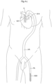
- Fig.1 shows the turbine pump 10 placed in a blood stream 16, such as in the aorta, in a human patient.
- the turbine pump 10 of the present invention provides the heart 3 of the human patient with additional pumping capacity.
- the turbine pump 10 can also be adapted to be placed in the heart, in the pulmonary artery, or in the blood stream in the abdominal aorta of the human patient. Consequently, Fig.3a shows the turbine pump 10 placed in a general blood stream 16, such as a blood vessel 17, in the human patient.
- a heart pump apparatus wherein the heart pump further comprises confining elements adapted to confine said rotating body in the longitudinal extension of the artery in which it is placed.
- Figs. 2a-b shows embodiments of the turbine pump 10.
- the turbine wheel 12 is preferably in the form of a longitudinal rotating body 18.
- the rotating body 18 has a cylindrical shape defined by an external cylindrical wall 20 with an outer surface 22 and an inner surface 24.
- blades 26 are provided.
- the blades 26 are extending radially or non-radially from the inner surface 24.
- the rotating body 18 have a longitudinal centre C in line with the blood stream 16.
- the respective blades 26 are not extending from the inner surface 24 all away to the centre C of the rotating body 18.
- the respective blades 26 have a first end 28 attached to the rotating body 18 and a second outer free end 30, which second free end 30 is placed at a distance from the centre C of the rotating body 18.
- the centre C of the rotation body 18 is preferably a void space extending in the longitudinal direction L of the rotating body 18. Consequently, the turbine pump 10 according to the present invention is a centre axis free turbine pump.
- the internal blades 26 arranged on the inner surface 24 of the rotating body 18 could have the purpose of eliminating friction generated by the blood that flows through the inside of the rotation body 18.
- the blades 26 can also make the external wall 20 of the rotating body 18 more stiffened.
- the rotating body 18 can be provided with blades 26 of different design and configuration.
- the incidence angles and the attack angles of the blades 26 are variable so that they can be arranged to yield the highest possible efficiency.
- the turbine pump 10 comprises a device for rotation of the rotating body 18.
- the device for rotation of the rotating body 18 can be a part of an electrically controlled arrangement.
- the stator 14 of the turbine pump is preferably provided.
- the stator 14 is preferably adapted to be placed outside the blood vessel 17 and opposite the rotating body 18.
- the electrically controlled arrangement includes elements E, shown with phantom lines in Figs. 2a-b , for receiving current to increase or decrease a magnetic field created at the stator 14, for providing rotation of the rotating body 18, by creating a magnetic field between the poles of the stator 14, that is provided for increasing or decreasing the rotation of the rotating body 18. Consequently, a turbine pump system for assisting the heart of a patient is provided, comprising a rotating body 18 and a stator 14.
- At least two rotating bodies 18', 18" can be implanted in sequence in the same blood vessel. If there are two rotating bodies in sequence, one 18' can be adapted to rotate clockwise (see arrow R1) and the following other rotating body 18" can be adapted to rotate counter clockwise (see arrow R2), or vice versa.
- Fig. 3c shows an embodiment of the heart pump device showing the drive unit, in which the stator 802 and rotor 18 is placed on the outside of the artery.
- the stator 802 and rotor 803 is confined in a housing 805 and is separated from the artery by a protective sheet 804 placed between the rotor 803 and artery, the protective sheet is preferably a thin plastic sheet providing a smooth surface for the rotor 803 to slide against.
- the rotor 803 rotates magnetic elements 809 which in turn rotates magnetic elements 810 of the rotating body 18 placed inside of the artery, by the magnetic elements 809 of the rotor 803 being in magnetic connection with the magnetic elements 810 of the rotor 18.
- the magnetic elements 809 of the rotor is the rotor 803.
- the present invention also relates to a method of surgically placing a rotating body 18 of a turbine pump 10 in a patient via a laparoscopic thoracic approach, the method comprising the steps of: inserting a needle or a tube like instrument into the thorax of the patient's body; using the needle or a tube like instrument to fill the thorax with gas thereby expanding the thoracic cavity; placing at least two laparoscopic trocars in the patient's body; inserting a camera through one of the laparoscopic trocars into the thorax; inserting at least one dissecting tool through one of said at least two laparoscopic trocars and dissecting an intended placement area of the patient; placing the rotating body 18 in any part of the blood stream in the thorax; and connecting a source of energy for powering the device.
- the present invention also relates to an operation method for surgically placing a rotating body 18 of a turbine pump 10 in a patient, the method comprising the steps of: cutting the patient's skin; opening the thoracic cavity; dissecting a placement area where to place the rotating body 18 inside a blood stream in the heart 3, or the aorta 4 or inside the pulmonary artery of the human patient; placing the a rotating body 18 in the placement area; and connecting a source of energy for powering the device.
- the present invention also relates to a method of surgically placing a rotating body 18 of a turbine pump 10 in a patient via a laparoscopic abdominal approach, the method comprising the steps of: inserting a needle or a tube like instrument into the abdomen of the patient's body; using the needle or a tube like instrument to fill the abdomen with gas thereby expanding the abdominal cavity; placing at least two laparoscopic trocars in the patient's body; inserting a camera through one of the laparoscopic trocars into the abdomen; inserting at least one dissecting tool through one of said at least two laparoscopic trocars and dissecting an intended placement area of the patient; placing the rotating body 18 in the blood stream in the abdominal aorta; and connecting a source of energy for powering the device.
- the present invention also relates to an operation method for surgically placing a rotating body 18 of a turbine pump 10 in a patient, the method comprising the steps of: cutting the patient's skin; opening the abdominal cavity; dissecting a placement area where to place the rotating body 18 in region of the abdominal aorta; placing the a rotating body in the blood stream in the abdominal aorta; and connecting a source of energy for powering the device.
- the present invention also relates to an operation method for surgically placing a rotating body 18 of a turbine pump 10 and stator 14 of a turbine pump 10 in a patient, via a laparoscopic thoracic approach, the method comprising the steps of: inserting a needle or a tube like instrument into the thorax of the patient's body; using the needle or a tube like instrument to fill the thorax with gas thereby expanding the thoracic cavity; placing at least two laparoscopic trocars in the patient's body; inserting a camera through one of the laparoscopic trocars into the thorax; inserting at least one dissecting tool through one of said at least two laparoscopic trocars and dissecting an intended placement area in the vascular system of the patient; placing the rotating body 18 in any part of the blood stream in the thorax, inside a blood stream of the blood vessel in the heart 3, or the aorta 4 or inside the pulmonary artery of the patient; placing the a stator 14 in the placement area, outside
- the present invention also relates to an operation method for surgically placing a rotating body 18 of a turbine pump 10 and stator 14 of a turbine pump 10 in a patient, the method comprising the steps of: cutting the patient's skin; opening the thoracic cavity; placing the rotating body 18 in any part of the blood stream in the thorax, inside a blood stream of the blood vessel in the heart 3, or the aorta 4 or inside the pulmonary artery of the patient; placing the a stator 14 in the placement area, outside the blood stream 16 of the blood vessel 17, outside the heart 3, or the aorta 4 or outside the pulmonary artery of the patient, placing said stator 14 on the outside of said rotating body 18, supplying wireless energy to said rotating body 18 causing rotating movement of said rotating body 18; and connecting a source of energy for powering said stator.
- the present invention also relates to an operation method for surgically placing a rotating body 18 of a turbine pump and stator 14 of a turbine pump 10 in a patient, via a laparoscopic abdominal approach, the method comprising the steps of: inserting a needle or a tube like instrument into the abdomen of the patient's body; using the needle or a tube like instrument to fill the thorax with gas thereby expanding the abdominal cavity; placing at least two laparoscopic trocars in the patient's body; inserting a camera through one of the laparoscopic trocars into the abdomen; inserting at least one dissecting tool through one of said at least two laparoscopic trocars and dissecting an intended placement area in the region of the abdominal aorta of the patient; placing the rotating body 18 inside the blood stream 16 in the abdominal aorta of the patient, placing the a stator 14 in the placement area, outside the blood stream of the abdominal aorta, placing said stator 14 on the outside of said rotating body, supplying wireless energy to said rotating body 18 causing
- the present invention also relates to an operation method for surgically placing a rotating body 18 of a turbine pump 10 and stator 14 of a turbine pump 10 in a patient, the method comprising the steps of: cutting the patient's skin, opening the abdominal cavity; placing the rotating body inside the blood stream 16 in the abdominal aorta of the patient, placing the a stator 14 in the placement area, outside the blood stream of the abdominal aorta, placing said stator 14 on the outside of said rotating body 18, supplying wireless energy to said rotating body 18 causing rotating movement of said rotating body 18; and connecting a source of energy for powering said stator.
- the present invention also relates to a method according to any of the operation methods or methods of surgically placing a rotating body 18 and/or a stator 14 as mentioned above, wherein said energy source is using energy, direct or indirect, from an external energy source, supplying energy non-invasively, without any penetration through the patient's skin to power the rotating body of a turbine pump 10.
- VAD blood pressure
- a pump that contains a metal plate that pushes on a plastic blood sac, forcing the blood out of the sac.
- the metal plate is driven by a miniature electric motor.
- the rotating body of the turbine pump can be arranged in a tube that pulls blood from the aorta, and sends back blood into the aorta.
- Fig. 3c The heart pump, wherein said second part is adapted to be a rotor, being cylindrical and placed outside said blood vessel, when implanted, adapted to be in magnetic connection with said rotating body such that said rotating body follows the rotations of said second part.
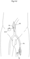
- Fig. 4b shows an operation method for surgically placing a rotating body 18 of a turbine pump 10 in an artery of a patient, via a laparoscopic inguinal approach, the method comprising the steps of: inserting a tube like instrument into the femoral artery FA of the patient's body and using the instrument to guide said rotating body 18 through the femoral artery FA to the aorta A and releasing the rotating body 18 inside of the aorta A. Thereafter the method comprises the step of placing a drive unit 814, at least partially encircling the aorta A.
- the drive unit 814 can be placed in a thoracic approach, by opening the thorax of the patient, or in an abdominal approach, reaching the heart 3 of the patient through the thoracic diaphragm.
- Fig. 4c shows a frontal view of the human patient after the operation has been performed and the incisions in the inguinal region 820 and the thorax 821 has been closed using sutures or staples.
- the drive unit 814 (here shown in phantom lines) is placed at least partially encircling the aorta A in proximity to the heart 3.
- Fig. 4d shows an operation method for surgically placing a rotating body 18 of a turbine pump 10, via a laparoscopic inguinal approach.
- the method comprises the steps of: inserting a tube like instrument into the femoral artery FA of the patient's body, using the instrument to guide the rotating body 18 through the femoral artery FA to the abdominal aorta AA. After the rotating body 18 has been guided to the abdominal artery AA through the femoral artery FA the rotating body 18 is released inside the artery.
- the drive unit 814 is inserted through an incision in the abdomen and placed at least partially encircling the abdominal artery AA, such that the drive unit 814 is placed in magnetic contact with the rotating body 18.
- Fig. 4e shows a frontal view of the patient after the incisions in the inguinal area 820 and the incisions in the thorax 821 has been closed using sutures or staples.
- the drive unit 814 (here shown in phantom lines) are placed partially encircling the abdominal artery AA in the abdomen.
- the clot removal device is preferably insertable in a blood flow passageway of the patient via surgery and is placed in the patient's abdomen or thorax or cephalic or neck region or retroperitoneal or any limb of the patient.
- Fig. 5 shows a sectional view wherein the blood clot removal device 100 is provided in the blood flow passageway provided by the second tube 2b.
- a filter 112 is provided across the blood flow passageway 114 formed in a housing 111 with the function of stopping potential blood clots brought forward in the second tube 2b by the blood flow, indicated by arrows in the figure.
- the filter 112 comprises a plurality of preferably equally spaced strips 112a of some suitable material, such as biocompatible metal or plastic. These strips 112a are preferably arranged mutual parallel.
- the distance between two adjacent strips is small enough to stop any blood clots.
- the distance is preferably less than 2 millimeters, and even more preferably less than 1.0 millimeters, but if the goal is to protect the brain from larger clots only the distance could be larger.
- the blood flow passageway 114 in the preferred embodiment has an essentially square cross-sectional shape, it will be realized that it can take any suitable shape, such as rectangular or circular.
- a laminar blood flow is achieved downstream of the filter, which is advantageous in a blood clot preventing perspective.
- the blood flow configuration can be further enhanced by giving the plurality of strips 112a a desired cross-sectional shape, although the rectangular shape shown in Fig. 7 will be adequate for most purposes.
- a first piston 116 is provided movable in a direction essentially perpendicular to the direction of the blood flow passageway 114, i.e., essentially perpendicular to the direction of the blood flow.
- This first piston 116 is driven by some suitable actuator means, such as pressurized air, a solenoid arrangement, an electrical servo motor or the like.
- a motor could be used to build up a stored power that could be released very fast, one example being a spring.
- pressurized air acts as the actuator means, since by latching the piston by means of a suitable latching means for the piston, building up the air pressure, and subsequently releasing the piston, very high speed of the piston is achieved, with enables short cleaning times of the filter.
- the outer end portion of the first piston 116 i.e., the end portion facing the blood flow passageway 114, is essentially flush with the wall of the blood flow passageway in a non-active state of the blood clot removal device 100. Also, the outer end portion is provided with a concave portion or recess 116a (exaggerated in the figures) in order to act as a blood clot capturing means, as will be explained below.
- the strike range of the first piston 116 is such that it extends all way across the blood flow passageway 14, as will be explained below with reference to Figs. 8-11 .
- a number of channels 116b corresponding to the number of strips 112a is provided in the first piston 16 to accommodate the strips when the first piston is in an extended position.
- the first piston 116 is also provided with a plurality of through holes 117 in the direction of the blood flow passageway. These through holes will allow blood to flow through the blood flow passageway also during a cleaning operation, as will be explained below with reference to Fig. 12 .
- a second piston 118 is provided across the blood flow passageway 114 from the first piston 116. Also this second piston 118 is movable in a direction essentially perpendicular to the direction of the blood flow passageway 114 and is biased in the direction thereof by means of a spring 118a, for example. Likewise, the outer end portion of the second piston is provided with a recess 18b similar to the recess 116a of the first piston 116.
- the first and second pistons 116, 118 are sealed to the housing 111 by means of a respective sealing 120, such as an O sealing.
- FIG. 8 is a view similar to that of Fig. 5 .
- this figures shows the blood clot removal device 100 during operation, wherein blood clots, generally designated 122, have assembled on the filter 112.
- the first piston 116 has moved linearly from the retracted starting position shown Fig. 8 to an extended position, wherein the outer end portion thereof is in contact with the second piston 118. Due to the recess 116a in the outer end of the first piston 116, the blood clots 122 have been assembled in the recess 116a, whereby they have been brought with the first piston 116 during the movement thereof. In the step shown in Fig. 9 , the blood clots are confined in the recess 116a between the first and second pistons 116, 118.
- the second piston 118 By moving the first piston 116 an additional distance from the position shown in Fig. 9 , the second piston 118 is pushed against the force of the spring 118a to a fully retracted position, see Fig. 10 .
- the plurality of strips 112a is in this position fully received in a respective channel 116b in the first piston. It is seen that the outer ends of the first and second pistons define an unobstructed cavity in which the blood clots are confined. It is thereby possible to remove these by some suitable means.
- One such means could be a third piston 124, which is movable in a direction perpendicular to both the direction of the blood flow passageway 114 and the direction of movement of the first and second pistons 116, 118.
- This third piston scrapes off the blood clots collected by the first piston 116 and moves them to a place outside of the blood clot removal device 100 and the blood flow passageway 114.
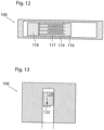
- Fig. 12 shows a side view of the first piston 116 in a fully extended position, i.e., corresponding to the view of Fig. 11 . It is here seen that in this position the through holes 117 will be aligned with the blood flow passageway 114, thereby allowing blood to flow therethrough also during cleaning of the filter 112.
- Fig. 13 shows a cross-sectional view taken along line X-X of Fig. 11 . It is here seen that the third piston 124 collects the blood clots 122 during a downward movement, indicated by an arrow in the figure. The clots are ejected from the blood clot removal device 100 when the third piston 124 has reached its lower end position, shown in Fig. 14 .
- pressurized air can be used for ejecting the collected blood clots from the cavity formed by the first piston 116 and the second piston 118.
- Fig. 15-28 shows the fixation of a heart pump apparatus to a structure of the human body comprising bone 240.
- the structure could be the sternum, a part of the rib cage, comprising one or more ribs or a part of the vertebral column comprising at least one vertebra.
- the heart pump apparatus 10 is fixated to the structure of the human body comprising bone 240 trough a fixating member 241 said fixating member could comprise a plate 242 which is in contact with the structure of the human body comprising bone 240.
- the heart pump apparatus 10 could also be fixated to the structure of the human body comprising bone 240 using a second fixating member 241b which also could comprise a plate 242b in which in turn could be in contact with the structure of the human body comprising bone 240.
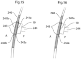
- Fig. 15 shows an embodiment where a heart pump apparatus 10 is fixated to a structure of the human body comprising bone 240.
- the structure could be the sternum, a part of the rib cage comprising one or more ribs or a part of the vertebral column structure comprising at least one vertebra.
- the heart pump apparatus 10 comprises a first fixating member 241a comprising a plate 242a and a second fixating member 241b comprising a plate 242b.
- the first and second fixating members are attached to each other using through-going screws 243 placed from the anterior side A of the structure of the human body comprising bone 240.
- An alternative embodiment could comprise screws placed from the posterior side P of the structure of the human body comprising bone 240.
- the first fixating member 241a and the second fixating member 241b clamp the structure of the human body comprising bone 240.
- the fixating member 241a could be in contact with a connecting arm 244 which in turn could be in contact with a heart pump device.
- Fig. 16 shows an embodiment where the heart pump apparatus 10 is fixated to a structure of the human body comprising bone 240 using only one fixating member 241a comprising a plate 242a.
- the structure could be the sternum, a part of the rib cage comprising one or more ribs or a part of the vertebral column structure comprising at least one vertebra.
- Through-going screws 243 is placed form the anterior side A the structure of the human body comprising bone 240 and fixated in the plate 242a.
- An alternative embodiment could comprise screws placed from the posterior side P of the structure of the human body comprising bone 240 in which case the screws could be fixated in nuts placed in connection with the structure of the human body comprising bone, or fixated in directly in the bone of the structure of the human body comprising bone 240.
- the fixating member 241a could be in contact with a connecting arm 244 which in turn could be in contact with a heart pump device.
- Fig. 17 shows an embodiment where the heart pump apparatus 10 is fixated to a structure of the human body comprising bone 240.
- the structure could be the sternum, a part of the rib cage comprising one or more ribs or a part of the vertebral column comprising at least one vertebra.
- the heart pump apparatus 10 comprises a first fixating member 241a comprising a plate 242a and a second fixating member 241b comprising a plate 242b.
- the first and second fixating members are attached to each other using through-going screws 243 placed from the posterior side P of the structure of the human body comprising bone 240.
- the screws are fixated to nuts 245 placed on the anterior side of the structure comprising bone 240.
- An alternative embodiment could comprise screws placed from the anterior side A of the structure of the human body comprising bone 240, in which case the nuts is placed on the posterior side P of the structure comprising bone 240.
- the first fixating member 241a and the second fixating member 241b clamp the structure of the human body comprising bone 240.
- the fixating member 241a could be in contact with a connecting arm 244 which in turn could be in contact with a heart pump device.
- Fig. 18 shows an embodiment where the heart pump apparatus 10 is fixated to a structure of the human body comprising bone 240 using only one fixating member 241a comprising a plate 242a.
- the structure could be the sternum, a part of the rib cage comprising one or more ribs or a part of the vertebral column structure comprising at least one vertebra.
- Screws 243 that fixates the fixating member to the structure of the human body comprising bone is placed form the posterior side P the structure of the human body comprising bone 240.
- the screws fixates the fixating member to both the posterior and the anterior cortex of the structure of the human body comprising bone 240, however it is conceivable that the screws are fixated only to the anterior or posterior cortex.
- An alternative embodiment could comprise screws placed from the anterior side A of the structure of the human body comprising bone 240, in which case the fixating member 241a is placed on the anterior side A of the structure of the human body comprising bone 240.
- Fig. 19 shows an embodiment where the heart pump apparatus 10 is fixated to a structure of the human body comprising bone 240 using one fixating member 241b comprising a plate 242b, and one fixating member 241a without a plate.
- the structure could be the sternum, a part of the rib cage comprising one or more ribs or a part of the vertebral column structure comprising at least one vertebra.
- Screws 243 that fixates the fixating members 241a,b to the structure of the human body comprising bone 240 is placed form the anterior side A of the structure of the human body comprising bone 240 and fixated in the fixating member 241a.
- the first fixating member 241a and the second fixating member 241b clamp the structure of the human body comprising bone 240.
- the fixating member 241a could be in contact with a connecting arm 244 which in turn could be in contact with a heart pump device.
- Fig. 20 shows an embodiment where the heart pump apparatus 10 is fixated to a structure of the human body comprising bone 240 using one fixating member 241b comprising a plate 242b, and one fixating member 241a without a plate.
- the structure could be the sternum, a part of the rib cage comprising one or more ribs or a part of the vertebral column structure comprising at least one vertebra.
- Screws 243 that fixates the fixating members 241a,b to the structure of the human body comprising bone 240 is placed form the posterior side P of the structure of the human body comprising bone 240 and fixated in the plate 242b of the fixating member 241b.
- the first fixating member 241a and the second fixating member 241b clamp the structure of the human body comprising bone 240.
- the fixating member 241a could be in contact with a connecting arm 244 which in turn could be in contact with a heart pump device.
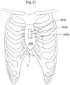
- Fig. 21 shows an embodiment where the heart pump apparatus 10 is adapted to be fixated to the sternum 250 of a human patient.
- the device is fixated using a fixating member 241b which is fixated to the sternum using screws 243.
- the heart pump apparatus could be fixated to the sternum 250 of a human patent using any of the ways to place the fixating members described previously.
- Fig. 23 shows an embodiment where the heart pump apparatus 10 is adapted to be fixated to two ribs 251, 252.
- a first plate 242a is provided on the posterior side of the rib cage, whereas a second plate 242b is provided in the anterior side of the rib cage.
- Screws 243 penetrate the ribs and fixates the first plate 242a to the second plate 242b. The tightening of the screws creates a clamping effect of the ribs 251,251 and provides the fixation of the heart pump apparatus 10.
- he screws 243 are placed between the ribs 251,252 and that ways provides a clamping effect of the ribs 251,252.
- Fig. 24 shows an embodiment where the heart pump apparatus 10 is adapted to be fixated to one rib 252.
- a plate 242a is provided on the posterior side of the rib cage and screws 243 are provided from the outside thereof, penetrating the rib 252 and fixating the plate 242a to the rib 252.
- Fig. 25 shows an embodiment where the heart pump apparatus 10 is adapted to be fixated to one rib 252 using cord or band 254, this way there is no need to penetrate the rib 252.
- the heart pump apparatus could be fixated to the ribcage of a human patent using any of the ways to place the fixating members described previously.
- Fig. 26 shows an embodiment where the heart pump apparatus 10 is adapted to be fixated to a vertebra 255 of the vertebral column.
- a fixating member 241 is fixated to the vertebra 255 using screws 243.
- the heart pump apparatus further comprises a connecting connecting arm 244 that connects the heart pump apparatus 10 to the fixating member 241.
- Fig. 27 shows an embodiment where the heart pump apparatus 10 is adapted to be fixated to two vertebras 255, 256 of the vertebral column.
- a fixating member 241 is fixated to the two vertebras 255, 256 using screws 243.
- the heart pump apparatus further comprises a connecting connecting arm 244 that connects the heart pump apparatus 10 to the fixating member 241.
- Fig. 28 shows an embodiment where the heart pump apparatus is adapted to be fixated to a vertebra 255 of the vertebral column by clamping said vertebra 255.
- Two fixating members 241a, 241b is placed on two sides of the vertebra and an attachment comprising screws 243 clamps the vertebra between the first and second fixating members 241a,b.
- the heart pump apparatus further comprises a connecting connecting arm 244 that connects the heart pump apparatus 10 to the fixating member 241.
- the means of attachment could be replaced with other mechanical attachments or an adhesive.
- Other mechanical attachments suitable could be: pop-rivets, nails, staples, band or cord.
- the mechanical fixating members could be of a metallic or ceramic material. Suitable metallic materials could be titanium or surgical steel.
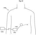
- Fig. 29 illustrates a system for treating a disease comprising an apparatus 10 of the present invention placed in the abdomen of a patient.
- An implanted energy-transforming device 1002 is adapted to supply energy consuming components of the apparatus with energy via a power supply line 1003.
- An external energy-transmission device 1004 for non-invasively energizing the apparatus 10 transmits energy by at least one wireless energy signal.
- the implanted energy-transforming device 1002 transforms energy from the wireless energy signal into electric energy which is supplied via the power supply line 1003.
- the implanted energy-transforming device 1002 may also comprise other components, such as: a coil for reception and/or transmission of signals and energy, an antenna for reception and/or transmission of signals, a microcontroller, a charge control unit, optionally comprising an energy storage, such as a capacitor, one or more sensors, such as temperature sensor, pressure sensor, position sensor, motion sensor etc., a transceiver, a motor, optionally including a motor controller, a pump, and other parts for controlling the operation of a medical implant.
- a coil for reception and/or transmission of signals and energy
- an antenna for reception and/or transmission of signals
- a microcontroller e.g., a microcontroller
- a charge control unit optionally comprising an energy storage, such as a capacitor
- sensors such as temperature sensor, pressure sensor, position sensor, motion sensor etc.
- a transceiver e.g., a motor controller, a pump, and other parts for controlling the operation of a medical implant.
- the wireless energy signal may include a wave signal selected from the following: a sound wave signal, an ultrasound wave signal, an electromagnetic wave signal, an infrared light signal, a visible light signal, an ultra violet light signal, a laser light signal, a micro wave signal, a radio wave signal, an x-ray radiation signal and a gamma radiation signal.
- the wireless energy signal may include an electric or magnetic field, or a combined electric and magnetic field.
- the wireless energy-transmission device 1004 may transmit a carrier signal for carrying the wireless energy signal.
- a carrier signal may include digital, analogue or a combination of digital and analogue signals.
- the wireless energy signal includes an analogue or a digital signal, or a combination of an analogue and digital signal.
- the wireless energy transmitted by the energy-transmission device 1004 may be used to directly power the apparatus, as the wireless energy is being transmitted by the energy-transmission device 1004.
- the system comprises an operation device for operating the apparatus, as will be described below, the wireless energy transmitted by the energy-transmission device 1004 may be used to directly power the operation device to create kinetic energy for the operation of the apparatus.
- the wireless energy of the first form may comprise sound waves and the energy-transforming device 1002 may include a piezo-electric element for transforming the sound waves into electric energy.
- the energy of the second form may comprise electric energy in the form of a direct current or pulsating direct current, or a combination of a direct current and pulsating direct current, or an alternating current or a combination of a direct and alternating current.
- the apparatus comprises electric components that are energized with electrical energy.
- Other implantable electric components of the system may be at least one voltage level guard or at least one constant current guard connected with the electric components of the apparatus.
- one of the energy of the first form and the energy of the second form may comprise magnetic energy, kinetic energy, sound energy, chemical energy, radiant energy, electromagnetic energy, photo energy, nuclear energy or thermal energy.
- one of the energy of the first form and the energy of the second form is non-magnetic, non-kinetic, non-chemical, non-sonic, non-nuclear or non-thermal.
- the energy-transmission device may be controlled from outside the patient's body to release electromagnetic wireless energy, and the released electromagnetic wireless energy is used for operating the apparatus.
- the energy-transmission device is controlled from outside the patient's body to release non-magnetic wireless energy, and the released non-magnetic wireless energy is used for operating the apparatus.
- the external energy-transmission device 1004 also includes a wireless remote control having an external signal transmitter for transmitting a wireless control signal for non-invasively controlling the apparatus.
- the control signal is received by an implanted signal receiver which may be incorporated in the implanted energy-transforming device 1002 or be separate there from.
- the wireless control signal may include a frequency, amplitude, or phase modulated signal or a combination thereof.
- the wireless control signal includes an analogue or a digital signal, or a combination of an analogue and digital signal.
- the wireless control signal comprises an electric or magnetic field, or a combined electric and magnetic field.
- the wireless remote control may transmit a carrier signal for carrying the wireless control signal.
- a carrier signal may include digital, analogue or a combination of digital and analogue signals.
- the control signal includes an analogue or a digital signal, or a combination of an analogue and digital signal
- the wireless remote control preferably transmits an electromagnetic carrier wave signal for carrying the digital or analogue control signals.
- Fig. 30 illustrates the system of Fig. 29 in the form of a more generalized block diagram showing the apparatus 10, the energy-transforming device 1002 powering the apparatus 10 via power supply line 1003, and the external energy-transmission device 1004,
- Fig. 31 shows an embodiment of the invention identical to that of Fig. 30 , except that a reversing device in the form of an electric switch 1006 operable for example by polarized energy also is implanted in the patient for reversing the apparatus 10.
- the wireless remote control of the external energy-transmission device 1004 transmits a wireless signal that carries polarized energy and the implanted energy-transforming device 1002 transforms the wireless polarized energy into a polarized current for operating the electric switch 1006.
- the electric switch 1006 reverses the function performed by the apparatus 10.
- Fig. 32 shows an embodiment of the invention identical to that of Fig. 30 , except that an operation device 1007 implanted in the patient for operating the apparatus 10 is provided between the implanted energy-transforming device 1002 and the apparatus 10.
- This operation device can be in the form of a motor 1007, such as an electric servomotor.
- the motor 1007 is powered with energy from the implanted energy-transforming device 1002, as the remote control of the external energy-transmission device 1004 transmits a wireless signal to the receiver of the implanted energy-transforming device 1002.
- the internal control unit is preferably programmable from outside the patient's body.
- the internal control unit is programmed to regulate the apparatus 10 according to a pre-programmed time-schedule or to input from any sensor sensing any possible physical parameter of the patient or any functional parameter of the system.
- the current condition of the patient may also be detected by means of suitable measuring devices or sensors, in order to provide parameters reflecting the patient's condition.
- suitable measuring devices or sensors in order to provide parameters reflecting the patient's condition.
- characteristics and/or parameters may be related to the current state of the apparatus 10, such as power consumption, operational mode and temperature, as well as the patient's condition reflected by parameters such as; body temperature, blood pressure, heartbeats and breathing.
- Other kinds of physical parameters of the patient and functional parameters of the device are described elsewhere.
- an energy source in the form of an accumulator 1016 may optionally be connected to the implanted energy-transforming device 1002 via the control unit 1015 for accumulating received energy for later use by the apparatus 10.
- characteristics of such an accumulator also reflecting the required amount of energy, may be measured as well.
- the accumulator may be replaced by a rechargeable battery, and the measured characteristics may be related to the current state of the battery, any electrical parameter such as energy consumption voltage, temperature, etc. In order to provide sufficient voltage and current to the apparatus 10, and also to avoid excessive heating, it is clearly understood that the battery should be charged optimally by receiving a correct amount of energy from the implanted energy-transforming device 1002, i.e. not too little or too much.
- the accumulator may also be a capacitor with corresponding characteristics.
- battery characteristics may be measured on a regular basis to determine the current state of the battery, which then may be stored as state information in a suitable storage means in the internal control unit 1015.
- state information in a suitable storage means in the internal control unit 1015.
- the internal control unit 1015 of the determination device is adapted to determine the energy balance and/or the currently required amount of energy, (either energy per time unit or accumulated energy) based on measurements made by the above-mentioned sensors or measuring devices of the apparatus 10, or the patient, or an implanted energy source if used, or any combination thereof.
- the internal control. unit 1015 is further connected to an internal signal transmitter 1027, arranged to transmit a control signal reflecting the determined required amount of energy, to an external signal receiver 1004c connected to the external control unit 1004b. The amount of energy transmitted from the external energy source 1004a may then be regulated in response to the received control signal.
- the determination device may include the external control unit 1004b.
- sensor measurements can be transmitted directly to the external control unit 1004b wherein the energy balance and/or the currently required amount of energy can be determined by the external control unit 1004b, thus integrating the above-described function of the internal control unit 1015 in the external control unit 1004b.
- the internal control unit 1015 can be omitted and the sensor measurements are supplied directly to the internal signal transmitter 1027 which sends the measurements over to the external signal receiver 1004c and the external control unit 1004b. The energy balance and the currently required amount of energy can then be determined by the external control unit 1004b based on those sensor measurements.
- the present solution according to the arrangement of Fig. 45 employs the feed back of information indicating the required energy, which is more efficient than previous solutions because it is based on the actual use of energy that is compared to the received energy, e.g. with respect to the amount of energy, the energy difference, or the energy receiving rate as compared to the energy rate used by implanted energy consuming components of the apparatus.
- the apparatus may use the received energy either for consuming or for storing the energy in an implanted energy source or the like.
- the different parameters discussed above would thus be used if relevant and needed and then as a tool for determining the actual energy balance. However, such parameters may also be needed per se for any actions taken internally to specifically operate the apparatus.
- the internal signal transmitter 1027 and the external signal receiver 1004c may be implemented as separate units using suitable signal transfer means, such as radio, IR (Infrared) or ultrasonic signals.
- suitable signal transfer means such as radio, IR (Infrared) or ultrasonic signals.
- the internal signal transmitter 1027 and the external signal receiver 1004c may be integrated in the implanted energy-transforming device 1002 and the external energy source 1004a, respectively, so as to convey control signals in a reverse direction relative to the energy transfer, basically using the same transmission technique.
- the control signals may be modulated with respect to frequency, phase or amplitude.
- the feedback information may be transferred either by a separate communication system including receivers and transmitters or may be integrated in the energy system.
- an integrated information feedback and energy system comprises an implantable internal energy receiver for receiving wireless energy, the energy receiver having an internal first coil and a first electronic circuit connected to the first coil, and an external energy transmitter for transmitting wireless energy, the energy transmitter having an external second coil and a second electronic circuit connected to the second coil.
- the external second coil of the energy transmitter transmits wireless energy which is received by the first coil of the energy receiver.
- the energy supply arrangement illustrated in Fig. 45 may operate basically in the following manner.
- the energy balance is first determined by the internal control unit 1015 of the determination device.
- a control signal reflecting the required amount of energy is also created by the internal control unit 1015, and the control signal is transmitted from the internal signal transmitter 1027 to the external signal receiver 1004c.
- the energy balance can be determined by the external control unit 1004b instead depending on the implementation, as mentioned above.
- the control signal may carry measurement results from various sensors.
- the amount of energy emitted from the external energy source 1004a can then be regulated by the external control unit 1004b, based on the determined energy balance, e.g. in response to the received control signal. This process may be repeated intermittently at certain intervals during ongoing energy transfer, or may be executed on a more or less continuous basis during the energy transfer.
- This system may also be used to obtain information about the coupling factors between the coils in a TET system even to calibrate the system both to find an optimal place for the external coil in relation to the internal coil and to optimize energy transfer. Simply comparing in this case the amount of energy transferred with the amount of energy received. For example if the external coil is moved the coupling factor may vary and correctly displayed movements could cause the external coil to find the optimal place for energy transfer.
- the external coil is adapted to calibrate the amount of transferred energy to achieve the feedback information in the determination device, before the coupling factor is maximized.
- the energy system of the present invention comprises an implantable internal energy receiver for receiving wireless energy, the energy receiver having an internal first coil and a first electronic circuit connected to the first coil, and an external energy transmitter for transmitting wireless energy, the energy transmitter having an external second coil and a second electronic circuit connected to the second coil.
- the external second coil of the energy transmitter transmits wireless energy which is received by the first coil of the energy receiver.
- This system further comprises a feedback device for communicating out the amount of energy received in the first coil as a feedback information
- the second electronic circuit includes a determination device for receiving the feedback information and for comparing the amount of transferred energy by the second coil with the feedback information related to the amount of energy received in the first coil to obtain the coupling factor between the first and second coils.
- the energy transmitter may regulate the transmitted energy in response to the obtained coupling factor.
- FIG. 46 Although wireless transfer of energy for operating the apparatus has been described above to enable non-invasive operation, it will be appreciated that the apparatus can be operated with wire bound energy as well.
- an external switch 1026 is interconnected between the external energy source 1004a and an operation device, such as an electric motor 1007 operating the apparatus 10.
- An external control unit 1004b controls the operation of the external switch 1026 to effect proper operation of the apparatus 10.
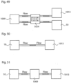
- Fig. 47 illustrates different embodiments for how received energy can be supplied to and used by the apparatus 10. Similar to the example of Fig. 45 , an internal energy receiver 1002 receives wireless energy E from an external energy source 1004a which is controlled by a transmission control unit 1004b.
- the internal energy receiver 1002 may comprise a constant voltage circuit, indicated as a dashed box “constant V" in the figure, for supplying energy at constant voltage to the apparatus 10.
- the internal energy receiver 1002 may further comprise a constant current circuit, indicated as a dashed box "constant C" in the figure, for supplying energy at constant current to the apparatus 10.
- the apparatus 10 comprises an energy consuming part 10a, which may be a motor, pump, restriction device, or any other medical appliance that requires energy for its electrical operation.
- the apparatus 10 may further comprise an energy storage device 10b for storing energy supplied from the internal energy receiver 1002.
- the supplied energy may be directly consumed by the energy consuming part 10a, or stored by the energy storage device 10b, or the supplied energy may be partly consumed and partly stored.
- the apparatus 10 may further comprise an energy stabilizing unit 10c for stabilizing the energy supplied from the internal energy receiver 1002.
- the energy may be supplied in a fluctuating manner such that it may be necessary to stabilize the energy before consumed or stored.
- the energy supplied from the internal energy receiver 1002 may further be accumulated and/or stabilized by a separate energy stabilizing unit 1028 located outside the apparatus 10, before being consumed and/or stored by the apparatus 10.
- the energy stabilizing unit 1028 may be integrated in the internal energy receiver 1002.
- the energy stabilizing unit 1028 may comprise a constant voltage circuit and/or a constant current circuit.
- Fig. 45 and Fig. 47 illustrate some possible but non-limiting implementation options regarding how the various shown functional components and elements can be arranged and connected to each other.
- Fig. 45 and Fig. 47 illustrate some possible but non-limiting implementation options regarding how the various shown functional components and elements can be arranged and connected to each other.
- the skilled person will readily appreciate that many variations and modifications can be made within the scope of the present invention.
- Fig. 48 schematically shows an energy balance measuring circuit of one of the proposed designs of the system for controlling transmission of wireless energy, or energy balance control system.
- the circuit has an output signal centered on 2.5V and proportionally related to the energy imbalance. The derivative of this signal shows if the value goes up and down and how fast such a change takes place. If the amount of received energy is lower than the energy used by implanted components of the apparatus, more energy is transferred and thus charged into the energy source.
- the output signal from the circuit is typically feed to an A/D converter and converted into a digital format. The digital information can then be sent to the external energy-transmission device allowing it to adjust the level of the transmitted energy.
- Another possibility is to have a completely analog system that uses comparators comparing the energy balance level with certain maximum and minimum thresholds sending information to external energy-transmission device if the balance drifts out of the max/min window.
- the schematic Fig. 48 shows a circuit implementation for a system that transfers energy to the implanted energy components of the apparatus of the present invention from outside of the patient's body using inductive energy transfer.
- An inductive energy transfer system typically uses an external transmitting coil and an internal receiving coil.
- the receiving coil, L1 is included in the schematic Fig. 31 ; the transmitting parts of the system are excluded.
- the energy may be transmitted for consumption and storage according to a transmission rate per time unit which is determined based on said parameters.
- the total amount of transmitted energy may also be determined based on said parameters.
- Fig. 52 shows a block diagram of a reversed servo system with a first closed system controlling a second closed system.
- the servo system comprises a regulation reservoir 1013 and a servo reservoir 1050.
- the servo reservoir 1050 mechanically controls an implanted apparatus 10 via a mechanical interconnection 1054.
- the apparatus has an expandable/contactable cavity. This cavity is preferably expanded or contracted by supplying hydraulic fluid from the larger adjustable reservoir 1052 in fluid connection with the apparatus 10. Alternatively, the cavity contains compressible gas, which can be compressed and expanded under the control of the servo reservoir 1050.
- the regulation reservoir 1013 is preferably provided with means 1013a for keeping its shape after compression. This means, which is schematically shown in the figure, will thus keep the apparatus 10 in a stretched position also when the user releases the regulation reservoir. In this way, the regulation reservoir essentially operates as an on/off switch for the system.
- the servo reservoir 1050 is mechanically connected to a larger adjustable reservoir 1052, in this example also having a bellow shape but with a larger diameter than the servo reservoir 1050.
- the larger adjustable reservoir 1052 is in fluid connection with the apparatus 10. This means that when a user pushes the regulation reservoir 1013, thereby displacing fluid from the regulation reservoir 1013 to the servo reservoir 1050, the expansion of the servo reservoir 1050 will displace a larger volume of fluid from the larger adjustable reservoir 1052 to the apparatus 10. In other words, in this reversed servo, a small volume in the regulation reservoir is compressed with a higher force and this creates a movement of a larger total area with less force per area unit.
- the method of the flow chart is also described with reference to fig. 4b .
- the area of dissection can of course be varied since the placing of the drive unit should be performed such that the drive unit is placed in magnetic connection with the rotating body 18.
- the following descriptions with reference to flow charts of figs 57 - 65 also describes operational methods with slight variations. However, the steps of these methods could be exchanged within or between the methods to adapt the method ti a particular procedure.
- Fig. 57 shows a flow chart of an operation method comprising the steps of:
- Fig. 60 shows a flow chart of an operation method comprising the steps of:
- Fig. 62 shows a flow chart of an operation method comprising the steps of:
- Fig. 65 shows a flow chart of an operation method comprising the steps of:
Landscapes
- Health & Medical Sciences (AREA)
- Engineering & Computer Science (AREA)
- Heart & Thoracic Surgery (AREA)
- General Health & Medical Sciences (AREA)
- Cardiology (AREA)
- Veterinary Medicine (AREA)
- Biomedical Technology (AREA)
- Public Health (AREA)
- Life Sciences & Earth Sciences (AREA)
- Animal Behavior & Ethology (AREA)
- Anesthesiology (AREA)
- Hematology (AREA)
- Mechanical Engineering (AREA)
- Vascular Medicine (AREA)
- Transplantation (AREA)
- Computer Networks & Wireless Communication (AREA)
- Medical Informatics (AREA)
- External Artificial Organs (AREA)
- Prostheses (AREA)
- Oral & Maxillofacial Surgery (AREA)
Priority Applications (1)
| Application Number | Priority Date | Filing Date | Title |
|---|---|---|---|
| EP21206386.1A EP4082601A1 (en) | 2008-10-10 | 2009-10-12 | Heart help pump, system, and method |
Applications Claiming Priority (4)
| Application Number | Priority Date | Filing Date | Title |
|---|---|---|---|
| SE0802161 | 2008-10-10 | ||
| US20238109P | 2009-02-24 | 2009-02-24 | |
| EP09819462.4A EP2344218B1 (en) | 2008-10-10 | 2009-10-12 | Heart help pump |
| PCT/SE2009/000445 WO2010042008A1 (en) | 2008-10-10 | 2009-10-12 | Heart help pump, system, and method |
Related Parent Applications (1)
| Application Number | Title | Priority Date | Filing Date |
|---|---|---|---|
| EP09819462.4A Division EP2344218B1 (en) | 2008-10-10 | 2009-10-12 | Heart help pump |
Related Child Applications (2)
| Application Number | Title | Priority Date | Filing Date |
|---|---|---|---|
| EP21206386.1A Division EP4082601A1 (en) | 2008-10-10 | 2009-10-12 | Heart help pump, system, and method |
| EP21206386.1A Division-Into EP4082601A1 (en) | 2008-10-10 | 2009-10-12 | Heart help pump, system, and method |
Publications (3)
| Publication Number | Publication Date |
|---|---|
| EP3906963A1 EP3906963A1 (en) | 2021-11-10 |
| EP3906963B1 true EP3906963B1 (en) | 2025-07-02 |
| EP3906963C0 EP3906963C0 (en) | 2025-07-02 |
Family
ID=42100790
Family Applications (3)
| Application Number | Title | Priority Date | Filing Date |
|---|---|---|---|
| EP21164363.0A Active EP3906963B1 (en) | 2008-10-10 | 2009-10-12 | Heart help pump |
| EP09819462.4A Active EP2344218B1 (en) | 2008-10-10 | 2009-10-12 | Heart help pump |
| EP21206386.1A Pending EP4082601A1 (en) | 2008-10-10 | 2009-10-12 | Heart help pump, system, and method |
Family Applications After (2)
| Application Number | Title | Priority Date | Filing Date |
|---|---|---|---|
| EP09819462.4A Active EP2344218B1 (en) | 2008-10-10 | 2009-10-12 | Heart help pump |
| EP21206386.1A Pending EP4082601A1 (en) | 2008-10-10 | 2009-10-12 | Heart help pump, system, and method |
Country Status (10)
Families Citing this family (74)
| Publication number | Priority date | Publication date | Assignee | Title |
|---|---|---|---|---|
| US6471635B1 (en) * | 2000-02-10 | 2002-10-29 | Obtech Medical Ag | Anal incontinence disease treatment with controlled wireless energy supply |
| US6464628B1 (en) | 1999-08-12 | 2002-10-15 | Obtech Medical Ag | Mechanical anal incontinence |
| US6482145B1 (en) | 2000-02-14 | 2002-11-19 | Obtech Medical Ag | Hydraulic anal incontinence treatment |
| DE60110747T2 (de) | 2000-02-10 | 2006-02-23 | Potencia Medical Ag | Mechanische vorrichtung zur impotenzbehandlung |
| CA2398544C (en) | 2000-02-11 | 2012-12-11 | Potencia Medical Ag | Impotence treatment apparatus with energy transforming means |
| ATE324087T1 (de) | 2000-02-14 | 2006-05-15 | Potencia Medical Ag | Männliche impotentzprothesevorrichtung mit drahtloser energieversorgung |
| EP1255513B1 (en) | 2000-02-14 | 2005-05-25 | Potencia Medical AG | Penile prosthesis |
| EP4088772A1 (en) * | 2008-01-28 | 2022-11-16 | Implantica Patent Ltd. | A drainage device |
| EP3928749A1 (en) | 2008-01-29 | 2021-12-29 | Implantica Patent Ltd. | A device for treating obesity |
| US8475355B2 (en) * | 2008-10-10 | 2013-07-02 | Milux Holding S.A. | Heart help device, system, and method |
| EP3120896A1 (en) | 2008-10-10 | 2017-01-25 | Kirk Promotion LTD. | A system, an apparatus, and a method for treating a sexual dysfunctional female patient |
| US10219898B2 (en) | 2008-10-10 | 2019-03-05 | Peter Forsell | Artificial valve |
| AU2009302904B2 (en) * | 2008-10-10 | 2016-03-03 | Medicaltree Patent Ltd | An improved artificial valve |
| US8600510B2 (en) | 2008-10-10 | 2013-12-03 | Milux Holding Sa | Apparatus, system and operation method for the treatment of female sexual dysfunction |
| US10668196B2 (en) * | 2008-10-10 | 2020-06-02 | Peter Forsell | Heart assisting device |
| EP2349078B1 (en) | 2008-10-10 | 2024-07-31 | Implantica Patent Ltd. | Fastening means for implantable medical control assembly |
| EP2344106B8 (en) | 2008-10-10 | 2022-07-20 | MedicalTree Patent Ltd. | Heart help device |
| WO2010042008A1 (en) * | 2008-10-10 | 2010-04-15 | Milux Holding Sa | Heart help pump, system, and method |
| EP2349383B1 (en) * | 2008-10-10 | 2021-07-21 | MedicalTree Patent Ltd. | Heart help device and system |
| CA3004075C (en) | 2008-10-10 | 2020-06-02 | Medicaltree Patent Ltd. | Heart help device, system, and method |
| US9949812B2 (en) | 2009-07-17 | 2018-04-24 | Peter Forsell | Vaginal operation method for the treatment of anal incontinence in women |
| US10952836B2 (en) | 2009-07-17 | 2021-03-23 | Peter Forsell | Vaginal operation method for the treatment of urinary incontinence in women |
| TR201200951A2 (tr) * | 2012-03-29 | 2012-09-21 | Oran B�Lent | Büyük arterlere yerleştirilen kalp destek cihazı. |
| WO2013082053A1 (en) * | 2011-11-28 | 2013-06-06 | MI-VAD, Inc. | Ventricular assist device and method |
| US8827889B2 (en) | 2012-05-21 | 2014-09-09 | University Of Washington Through Its Center For Commercialization | Method and system for powering implantable devices |
| US11621583B2 (en) | 2012-05-21 | 2023-04-04 | University Of Washington | Distributed control adaptive wireless power transfer system |
| TR201207222A2 (tr) * | 2012-06-21 | 2012-11-21 | Oran B�Lent | Damar içi kalp destek cihazı. |
| WO2015021493A1 (en) * | 2013-08-16 | 2015-02-19 | Thorvascular Pty Ltd | Heart assist system and/or device |
| US9314559B2 (en) * | 2013-08-30 | 2016-04-19 | Steve Smith | Four chamber redundant-impeller artificial heart |
| CN103446634B (zh) * | 2013-09-09 | 2015-07-29 | 北京工业大学 | 一种人工心脏自平衡体外磁驱动系统 |
| EP3110468B1 (en) | 2014-02-25 | 2021-11-03 | Kushwaha, Sudhir | Ventricular assist device and method |
| US10729834B2 (en) | 2014-12-19 | 2020-08-04 | Yale University | Heart failure recovery device and method of treatment |
| US20170258593A1 (en) * | 2016-03-09 | 2017-09-14 | David Good | Cardiac assistance device |
| KR102023617B1 (ko) * | 2016-03-22 | 2019-09-20 | 삼성전자주식회사 | 이식형 의료장치에 전력을 공급하는 방법 및 이를 이용하는 전력공급시스템 |
| US10589013B2 (en) | 2016-08-26 | 2020-03-17 | Tci Llc | Prosthetic rib with integrated percutaneous connector for ventricular assist devices |
| US10894114B2 (en) | 2017-01-12 | 2021-01-19 | Tc1 Llc | Driveline bone anchors and methods of use |
| EP4233989A3 (en) | 2017-06-07 | 2023-10-11 | Shifamed Holdings, LLC | Intravascular fluid movement devices, systems, and methods of use |
| FR3071283B1 (fr) * | 2017-09-21 | 2022-07-29 | Fineheart | Pompe cardiaque equipee d'une turbine a pales internes |
| WO2019094963A1 (en) | 2017-11-13 | 2019-05-16 | Shifamed Holdings, Llc | Intravascular fluid movement devices, systems, and methods of use |
| DE102018201030A1 (de) | 2018-01-24 | 2019-07-25 | Kardion Gmbh | Magnetkuppelelement mit magnetischer Lagerungsfunktion |
| US10722631B2 (en) | 2018-02-01 | 2020-07-28 | Shifamed Holdings, Llc | Intravascular blood pumps and methods of use and manufacture |
| DE102018207575A1 (de) | 2018-05-16 | 2019-11-21 | Kardion Gmbh | Magnetische Stirndreh-Kupplung zur Übertragung von Drehmomenten |
| DE102018207611A1 (de) | 2018-05-16 | 2019-11-21 | Kardion Gmbh | Rotorlagerungssystem |
| DE102018208539A1 (de) | 2018-05-30 | 2019-12-05 | Kardion Gmbh | Motorgehäusemodul zum Abdichten eines Motorraums eines Motors eines Herzunterstützungssystems und Herzunterstützungssystem und Verfahren zum Montieren eines Herzunterstützungssystems |
| DE102018208541A1 (de) | 2018-05-30 | 2019-12-05 | Kardion Gmbh | Axialpumpe für ein Herzunterstützungssystem und Verfahren zum Herstellen einer Axialpumpe für ein Herzunterstützungssystem |
| DE102018208550A1 (de) | 2018-05-30 | 2019-12-05 | Kardion Gmbh | Leitungsvorrichtung zum Leiten eines Blutstroms für ein Herzunterstützungssystem, Herzunterstützungssystem und Verfahren zum Herstellen einer Leitungsvorrichtung |
| DE102018208538A1 (de) | 2018-05-30 | 2019-12-05 | Kardion Gmbh | Intravasale Blutpumpe und Verfahren zur Herstellung von elektrischen Leiterbahnen |
| CN112566689A (zh) * | 2018-06-13 | 2021-03-26 | 耶鲁大学 | 心内装置 |
| DE102018210058A1 (de) | 2018-06-21 | 2019-12-24 | Kardion Gmbh | Statorschaufelvorrichtung zur Strömungsführung eines aus einer Austrittsöffnung eines Herzunterstützungssystems ausströmenden Fluids, Herzunterstützungssystem mit Statorschaufelvorrichtung, Verfahren zum Betreiben einer Statorschaufelvorrichtung und Herstellverfahren |
| DE102018210076A1 (de) | 2018-06-21 | 2019-12-24 | Kardion Gmbh | Verfahren und Vorrichtung zum Erkennen eines Verschleißzustands eines Herzunterstützungssystems, Verfahren und Vorrichtung zum Betreiben eines Herzunterstützungssystems und Herzunterstützungssystem |
| DE102018211327A1 (de) | 2018-07-10 | 2020-01-16 | Kardion Gmbh | Laufrad für ein implantierbares, vaskuläres Unterstützungssystem |
| DE102018212153A1 (de) | 2018-07-20 | 2020-01-23 | Kardion Gmbh | Zulaufleitung für eine Pumpeneinheit eines Herzunterstützungssystems, Herzunterstützungssystem und Verfahren zum Herstellen einer Zulaufleitung für eine Pumpeneinheit eines Herzunterstützungssystems |
| US11179571B2 (en) | 2018-07-31 | 2021-11-23 | Manicka Institute Llc | Subcutaneous device for monitoring and/or providing therapies |
| US12161857B2 (en) | 2018-07-31 | 2024-12-10 | Shifamed Holdings, Llc | Intravascular blood pumps and methods of use |
| US11660444B2 (en) | 2018-07-31 | 2023-05-30 | Manicka Institute Llc | Resilient body component contact for a subcutaneous device |
| US10716511B2 (en) | 2018-07-31 | 2020-07-21 | Manicka Institute Llc | Subcutaneous device for monitoring and/or providing therapies |
| US10576291B2 (en) | 2018-07-31 | 2020-03-03 | Manicka Institute Llc | Subcutaneous device |
| US11433233B2 (en) | 2020-11-25 | 2022-09-06 | Calyan Technologies, Inc. | Electrode contact for a subcutaneous device |
| US11717674B2 (en) | 2018-07-31 | 2023-08-08 | Manicka Institute Llc | Subcutaneous device for use with remote device |
| JP2021532931A (ja) | 2018-08-07 | 2021-12-02 | カルディオン ゲーエムベーハーKardion Gmbh | 心臓補助システム用ベアリング装置、および心臓補助システム用ベアリング装置内の中間空間のフラッシング方法 |
| US12220570B2 (en) | 2018-10-05 | 2025-02-11 | Shifamed Holdings, Llc | Intravascular blood pumps and methods of use |
| WO2021062083A1 (en) * | 2019-09-25 | 2021-04-01 | Bionet Sonar | Systems and methods for using ultrasonic waves for wireless powering and communication of a cardiac assist device |
| EP3934709A4 (en) * | 2019-03-08 | 2022-12-28 | Summacor, Inc. | Positive displacement shuttle pump heart and vad |
| WO2021011473A1 (en) | 2019-07-12 | 2021-01-21 | Shifamed Holdings, Llc | Intravascular blood pumps and methods of manufacture and use |
| US11654275B2 (en) | 2019-07-22 | 2023-05-23 | Shifamed Holdings, Llc | Intravascular blood pumps with struts and methods of use and manufacture |
| US12102815B2 (en) | 2019-09-25 | 2024-10-01 | Shifamed Holdings, Llc | Catheter blood pumps and collapsible pump housings |
| US12121713B2 (en) | 2019-09-25 | 2024-10-22 | Shifamed Holdings, Llc | Catheter blood pumps and collapsible blood conduits |
| WO2021062265A1 (en) | 2019-09-25 | 2021-04-01 | Shifamed Holdings, Llc | Intravascular blood pump systems and methods of use and control thereof |
| US11839708B2 (en) | 2019-10-19 | 2023-12-12 | SummaCor, Inc. | Linear cardiac assist pulsatile pump |
| DE102020102474A1 (de) | 2020-01-31 | 2021-08-05 | Kardion Gmbh | Pumpe zum Fördern eines Fluids und Verfahren zum Herstellen einer Pumpe |
| US10987060B1 (en) | 2020-09-14 | 2021-04-27 | Calyan Technologies, Inc. | Clip design for a subcutaneous device |
| JP2024507841A (ja) | 2021-02-22 | 2024-02-21 | サマコア, インコーポレイテッド | 線形心臓補助拍動性ポンプ |
| WO2022254438A1 (en) * | 2021-06-02 | 2022-12-08 | Cardionyx Heart Science Ltd. | In-vivo micro blood pump |
| CN114452527B (zh) * | 2022-01-26 | 2023-04-25 | 苏州心擎医疗技术有限公司 | 用于对心脏在发生功能衰竭时进行辅助的装置 |
Family Cites Families (53)
| Publication number | Priority date | Publication date | Assignee | Title |
|---|---|---|---|---|
| US2500400A (en) * | 1946-10-25 | 1950-03-14 | Byron A Cogswell | Axial flow pump |
| GB885674A (en) * | 1959-07-20 | 1961-12-28 | Interscience Res Corp | Improvements in or relating to mechanical hearts |
| US4304225A (en) * | 1979-04-30 | 1981-12-08 | Lloyd And Associates | Control system for body organs |
| US4688998A (en) * | 1981-03-18 | 1987-08-25 | Olsen Don B | Magnetically suspended and rotated impellor pump apparatus and method |
| WO1982003176A1 (en) * | 1981-03-18 | 1982-09-30 | Bramm Guenter Walter Otto | Megnetically suspended and rotated impellor pump apparatus and method |
| US4625712A (en) * | 1983-09-28 | 1986-12-02 | Nimbus, Inc. | High-capacity intravascular blood pump utilizing percutaneous access |
| US4779614A (en) * | 1987-04-09 | 1988-10-25 | Nimbus Medical, Inc. | Magnetically suspended rotor axial flow blood pump |
| US4995857A (en) * | 1989-04-07 | 1991-02-26 | Arnold John R | Left ventricular assist device and method for temporary and permanent procedures |
| US5112202A (en) * | 1990-01-31 | 1992-05-12 | Ntn Corporation | Turbo pump with magnetically supported impeller |
| US5211546A (en) * | 1990-05-29 | 1993-05-18 | Nu-Tech Industries, Inc. | Axial flow blood pump with hydrodynamically suspended rotor |
| US5112200A (en) * | 1990-05-29 | 1992-05-12 | Nu-Tech Industries, Inc. | Hydrodynamically suspended rotor axial flow blood pump |
| US5429584A (en) * | 1990-11-09 | 1995-07-04 | Mcgill University | Cardiac assist method and apparatus |
| US5290227A (en) * | 1992-08-06 | 1994-03-01 | Pasque Michael K | Method of implanting blood pump in ascending aorta or main pulmonary artery |
| US6302661B1 (en) * | 1996-05-03 | 2001-10-16 | Pratap S. Khanwilkar | Electromagnetically suspended and rotated centrifugal pumping apparatus and method |
| US5851174A (en) * | 1996-09-17 | 1998-12-22 | Robert Jarvik | Cardiac support device |
| JP4104088B2 (ja) * | 1996-10-04 | 2008-06-18 | ユナイテッド ステイツ サージカル コーポレイション | 循環器支援システム |
| US5964694A (en) * | 1997-04-02 | 1999-10-12 | Guidant Corporation | Method and apparatus for cardiac blood flow assistance |
| US5951262A (en) * | 1997-04-18 | 1999-09-14 | Centriflow Llc | Mechanism for providing motive force and for pumping applications |
| US6547821B1 (en) * | 1998-07-16 | 2003-04-15 | Cardiothoracic Systems, Inc. | Surgical procedures and devices for increasing cardiac output of the heart |
| US6149683A (en) * | 1998-10-05 | 2000-11-21 | Kriton Medical, Inc. | Power system for an implantable heart pump |
| US6454999B1 (en) * | 1998-12-30 | 2002-09-24 | Cardiovention, Inc. | Integrated blood pump and oxygenator system having extended blood flow path |
| US6428747B1 (en) * | 1998-12-30 | 2002-08-06 | Cardiovention, Inc. | Integrated extracorporeal blood oxygenator, pump and heat exchanger system |
| CA2379427C (en) | 1999-08-12 | 2009-07-21 | Potencia Medical Ag | Medical implant apparatus with wireless energy transmission |
| JP2001207988A (ja) * | 2000-01-26 | 2001-08-03 | Nipro Corp | 磁気駆動型軸流ポンプ |
| US6623507B2 (en) * | 2001-05-07 | 2003-09-23 | Fathy M.A. Saleh | Vascular filtration device |
| US7998190B2 (en) * | 2002-06-17 | 2011-08-16 | California Institute Of Technology | Intravascular miniature stent pump |
| JP2004278375A (ja) * | 2003-03-14 | 2004-10-07 | Yasuhiro Fukui | 軸流ポンプ |
| CA2428741A1 (en) * | 2003-05-13 | 2004-11-13 | Cardianove Inc. | Dual inlet mixed-flow blood pump |
| US8419609B2 (en) * | 2005-10-05 | 2013-04-16 | Heartware Inc. | Impeller for a rotary ventricular assist device |
| US7544160B2 (en) * | 2005-02-10 | 2009-06-09 | Yossi Gross | Extracardiac blood flow amplification device |
| EP1893075A4 (en) * | 2005-06-08 | 2013-06-19 | Micromed Technology Inc | ARTIFICIAL HEART SYSTEM |
| EP1738783A1 (de) * | 2005-07-01 | 2007-01-03 | Universitätsspital Basel | Axialpumpe mit spiralförmiger Schaufel |
| US20130209292A1 (en) * | 2005-07-01 | 2013-08-15 | Doan Baykut | Axial flow blood pump with hollow rotor |
| AU2006297779B8 (en) * | 2005-10-05 | 2013-03-21 | Heartware, Inc. | Axial flow pump with multi-grooved rotor |
| AU2007269050A1 (en) * | 2006-07-06 | 2008-01-10 | The Board Of Regents Of The University Of Texas System | Positive displacement pump system and method |
| CA2662060A1 (en) * | 2006-08-31 | 2008-03-06 | Smartin Technologies, Llc | Modular magneto mechanical device |
| AU2008219653B2 (en) * | 2007-02-26 | 2014-01-16 | Heartware, Inc. | Intravascular ventricular assist device |
| US8075472B2 (en) * | 2007-05-03 | 2011-12-13 | Leviticus-Cardio Ltd. | Permanent ventricular assist device for treating heart failure |
| GB0713864D0 (en) | 2007-07-17 | 2007-08-29 | Sheppard & Charnley Ltd | Electric motor/generator assembly |
| US7794384B2 (en) * | 2007-12-07 | 2010-09-14 | Terumo Heart, Inc. | Dual communication interface for artificial heart system |
| US10668196B2 (en) | 2008-10-10 | 2020-06-02 | Peter Forsell | Heart assisting device |
| US8475355B2 (en) | 2008-10-10 | 2013-07-02 | Milux Holding S.A. | Heart help device, system, and method |
| WO2010042008A1 (en) * | 2008-10-10 | 2010-04-15 | Milux Holding Sa | Heart help pump, system, and method |
| CA3004075C (en) | 2008-10-10 | 2020-06-02 | Medicaltree Patent Ltd. | Heart help device, system, and method |
| EP2349383B1 (en) | 2008-10-10 | 2021-07-21 | MedicalTree Patent Ltd. | Heart help device and system |
| US8386040B2 (en) * | 2009-04-16 | 2013-02-26 | The Board Of Regents Of The University Of Texas Systems | System and method for pump variable stroke |
| EP2298373A1 (de) * | 2009-09-22 | 2011-03-23 | ECP Entwicklungsgesellschaft mbH | Fluidpumpe mit wenigstens einem Schaufelblatt und einer Stützeinrichtung |
| US9555174B2 (en) * | 2010-02-17 | 2017-01-31 | Flow Forward Medical, Inc. | Blood pump systems and methods |
| US9662431B2 (en) * | 2010-02-17 | 2017-05-30 | Flow Forward Medical, Inc. | Blood pump systems and methods |
| AU2012296568A1 (en) * | 2011-08-17 | 2014-03-06 | Flow Forward Medical, Inc. | Blood pump systems and methods |
| US8849398B2 (en) * | 2011-08-29 | 2014-09-30 | Minnetronix, Inc. | Expandable blood pump for cardiac support |
| US10294944B2 (en) * | 2013-03-08 | 2019-05-21 | Everheart Systems Inc. | Flow thru mechanical blood pump bearings |
| US10702641B2 (en) * | 2015-06-29 | 2020-07-07 | Tc1 Llc | Ventricular assist devices having a hollow rotor and methods of use |
-
2009
- 2009-10-12 WO PCT/SE2009/000445 patent/WO2010042008A1/en active Application Filing
- 2009-10-12 EP EP21164363.0A patent/EP3906963B1/en active Active
- 2009-10-12 EP EP09819462.4A patent/EP2344218B1/en active Active
- 2009-10-12 HU HUE09819462A patent/HUE055876T2/hu unknown
- 2009-10-12 JP JP2011530986A patent/JP5539999B2/ja active Active
- 2009-10-12 SI SI200932133T patent/SI2344218T1/sl unknown
- 2009-10-12 EP EP21206386.1A patent/EP4082601A1/en active Pending
- 2009-10-12 AU AU2009302931A patent/AU2009302931B2/en not_active Ceased
- 2009-10-12 PL PL09819462T patent/PL2344218T3/pl unknown
- 2009-10-12 CA CA3049191A patent/CA3049191C/en active Active
- 2009-10-12 US US13/123,231 patent/US9180235B2/en active Active
- 2009-10-12 CA CA3126252A patent/CA3126252A1/en active Pending
- 2009-10-12 CA CA2776421A patent/CA2776421C/en active Active
-
2015
- 2015-11-06 US US14/934,227 patent/US11376416B2/en active Active
-
2021
- 2021-07-05 CY CY20211100599T patent/CY1125034T1/el unknown
-
2022
- 2022-07-01 US US17/855,844 patent/US20220401719A1/en active Pending
Also Published As
| Publication number | Publication date |
|---|---|
| EP4082601A1 (en) | 2022-11-02 |
| EP3906963A1 (en) | 2021-11-10 |
| US20160129169A1 (en) | 2016-05-12 |
| AU2009302931B2 (en) | 2015-10-29 |
| US20110201870A1 (en) | 2011-08-18 |
| EP2344218A1 (en) | 2011-07-20 |
| JP2012505014A (ja) | 2012-03-01 |
| EP2344218B1 (en) | 2021-04-07 |
| CA3049191A1 (en) | 2010-04-15 |
| US9180235B2 (en) | 2015-11-10 |
| US11376416B2 (en) | 2022-07-05 |
| US20220401719A1 (en) | 2022-12-22 |
| JP5539999B2 (ja) | 2014-07-02 |
| CA2776421C (en) | 2020-06-02 |
| CA2776421A1 (en) | 2010-04-15 |
| CY1125034T1 (el) | 2023-03-24 |
| HUE055876T2 (hu) | 2021-12-28 |
| PL2344218T3 (pl) | 2022-01-10 |
| EP2344218A4 (en) | 2016-11-23 |
| AU2009302931A1 (en) | 2010-04-15 |
| CA3049191C (en) | 2023-08-29 |
| EP3906963C0 (en) | 2025-07-02 |
| SI2344218T1 (sl) | 2021-09-30 |
| CA3126252A1 (en) | 2010-04-15 |
| WO2010042008A1 (en) | 2010-04-15 |
Similar Documents
| Publication | Publication Date | Title |
|---|---|---|
| US20220401719A1 (en) | Heart help pump, system, and method | |
| US12232954B2 (en) | Artificial valve | |
| AU2018271406B2 (en) | Heart Help Device, System, And Method | |
| EP2349097B1 (en) | An improved artificial valve | |
| US10219898B2 (en) | Artificial valve | |
| US20190314150A1 (en) | Artificial valve | |
| ES2879394T3 (es) | Bomba de ayuda al corazón, sistema y método |
Legal Events
| Date | Code | Title | Description |
|---|---|---|---|
| PUAI | Public reference made under article 153(3) epc to a published international application that has entered the european phase |
Free format text: ORIGINAL CODE: 0009012 |
|
| STAA | Information on the status of an ep patent application or granted ep patent |
Free format text: STATUS: THE APPLICATION HAS BEEN PUBLISHED |
|
| AC | Divisional application: reference to earlier application |
Ref document number: 2344218 Country of ref document: EP Kind code of ref document: P |
|
| AK | Designated contracting states |
Kind code of ref document: A1 Designated state(s): AT BE BG CH CY CZ DE DK EE ES FI FR GB GR HR HU IE IS IT LI LT LU LV MC MK MT NL NO PL PT RO SE SI SK SM TR |
|
| B565 | Issuance of search results under rule 164(2) epc |
Effective date: 20211008 |
|
| STAA | Information on the status of an ep patent application or granted ep patent |
Free format text: STATUS: REQUEST FOR EXAMINATION WAS MADE |
|
| 17P | Request for examination filed |
Effective date: 20220510 |
|
| RBV | Designated contracting states (corrected) |
Designated state(s): AT BE BG CH CY CZ DE DK EE ES FI FR GB GR HR HU IE IS IT LI LT LU LV MC MK MT NL NO PL PT RO SE SI SK SM TR |
|
| STAA | Information on the status of an ep patent application or granted ep patent |
Free format text: STATUS: EXAMINATION IS IN PROGRESS |
|
| 17Q | First examination report despatched |
Effective date: 20240503 |
|
| RAP3 | Party data changed (applicant data changed or rights of an application transferred) |
Owner name: MEDICALTREE PATENTS LTD |
|
| REG | Reference to a national code |
Ref country code: DE Ref legal event code: R079 Free format text: PREVIOUS MAIN CLASS: A61M0060419000 Ipc: A61M0060135000 Ref country code: DE Ref legal event code: R079 Ref document number: 602009065549 Country of ref document: DE Free format text: PREVIOUS MAIN CLASS: A61M0060419000 Ipc: A61M0060135000 |
|
| RIC1 | Information provided on ipc code assigned before grant |
Ipc: A61M 60/531 20210101ALI20241219BHEP Ipc: A61M 60/873 20210101ALI20241219BHEP Ipc: A61M 60/422 20210101ALI20241219BHEP Ipc: A61M 60/139 20210101ALI20241219BHEP Ipc: A61M 60/816 20210101ALI20241219BHEP Ipc: A61M 60/806 20210101ALI20241219BHEP Ipc: A61M 60/804 20210101ALI20241219BHEP Ipc: A61M 60/237 20210101ALI20241219BHEP Ipc: A61M 60/135 20210101AFI20241219BHEP |
|
| GRAP | Despatch of communication of intention to grant a patent |
Free format text: ORIGINAL CODE: EPIDOSNIGR1 |
|
| STAA | Information on the status of an ep patent application or granted ep patent |
Free format text: STATUS: GRANT OF PATENT IS INTENDED |
|
| INTG | Intention to grant announced |
Effective date: 20250127 |
|
| GRAS | Grant fee paid |
Free format text: ORIGINAL CODE: EPIDOSNIGR3 |
|
| GRAA | (expected) grant |
Free format text: ORIGINAL CODE: 0009210 |
|
| STAA | Information on the status of an ep patent application or granted ep patent |
Free format text: STATUS: THE PATENT HAS BEEN GRANTED |
|
| AC | Divisional application: reference to earlier application |
Ref document number: 2344218 Country of ref document: EP Kind code of ref document: P |
|
| AK | Designated contracting states |
Kind code of ref document: B1 Designated state(s): AT BE BG CH CY CZ DE DK EE ES FI FR GB GR HR HU IE IS IT LI LT LU LV MC MK MT NL NO PL PT RO SE SI SK SM TR |
|
| REG | Reference to a national code |
Ref country code: GB Ref legal event code: FG4D |
|
| REG | Reference to a national code |
Ref country code: CH Ref legal event code: EP |
|
| REG | Reference to a national code |
Ref country code: DE Ref legal event code: R096 Ref document number: 602009065549 Country of ref document: DE |
|
| REG | Reference to a national code |
Ref country code: IE Ref legal event code: FG4D |
|
| U01 | Request for unitary effect filed |
Effective date: 20250702 |
|
| U07 | Unitary effect registered |
Designated state(s): AT BE BG DE DK EE FI FR IT LT LU LV MT NL PT RO SE SI Effective date: 20250709 |