EP3906372B1 - Sensorring zur überwachung des betriebs einer mechanischen dichtungsanordnung - Google Patents
Sensorring zur überwachung des betriebs einer mechanischen dichtungsanordnung Download PDFInfo
- Publication number
- EP3906372B1 EP3906372B1 EP19813911.5A EP19813911A EP3906372B1 EP 3906372 B1 EP3906372 B1 EP 3906372B1 EP 19813911 A EP19813911 A EP 19813911A EP 3906372 B1 EP3906372 B1 EP 3906372B1
- Authority
- EP
- European Patent Office
- Prior art keywords
- sensor
- ring
- cavity
- recited
- sensor ring
- Prior art date
- Legal status (The legal status is an assumption and is not a legal conclusion. Google has not performed a legal analysis and makes no representation as to the accuracy of the status listed.)
- Active
Links
Images


Classifications
-
- F—MECHANICAL ENGINEERING; LIGHTING; HEATING; WEAPONS; BLASTING
- F16—ENGINEERING ELEMENTS AND UNITS; GENERAL MEASURES FOR PRODUCING AND MAINTAINING EFFECTIVE FUNCTIONING OF MACHINES OR INSTALLATIONS; THERMAL INSULATION IN GENERAL
- F16J—PISTONS; CYLINDERS; SEALINGS
- F16J15/00—Sealings
- F16J15/16—Sealings between relatively-moving surfaces
- F16J15/34—Sealings between relatively-moving surfaces with slip-ring pressed against a more or less radial face on one member
- F16J15/3492—Sealings between relatively-moving surfaces with slip-ring pressed against a more or less radial face on one member with monitoring or measuring means associated with the seal
Definitions
- the present invention relates to a sensor ring for monitoring the operation of a mechanical sealing arrangement in accordance with the preamble of claim 1.
- US-A-6,065,345 discusses a method of monitoring the condition of a mechanical seal in an apparatus provided with a rotating part, in particular in a pump, which has a rotating shaft for the forwarding of a fluid.
- the sound emission of the seal is continually measured at discrete times in the operating state of the apparatus and at least one statistical characteristic value is won from the acoustic signals.
- the goal in the above discussed patent is to monitor the sliding condition of the seal. In other words, if the seal is starting to run dry, i.e. the flushing is, for some reason, not working properly, the acoustic emission from the seal changes with the condition of the lubricating film.
- the US- patent discusses also the effect of the speed of rotation of the pump, the temperature of the flushing liquid, the pressure of the fluid to be pumped, etc. on the acoustic emission of the seal, whereby the acoustic emission may change even if the sliding conditions were not changed.
- US-B1-6,360,610 discusses a system and a method that are particularly suited for monitoring the interface of two liquid lubricated mechanical seal faces.
- the system monitors an interface by using a wave source to produce an ultrasonic shear wave, directing the wave at the interface, detecting the wave after it interacts with the interface, and comparing the detected wave to predetermined wave characteristics. Based on the comparison, an alarm may be triggered. The alarm may indicate that the mechanical seal is failing.
- the approach involves detecting the collapse of the lubricating film between the seal faces and detecting excessive asperity contact. The collapse of the lubricating film and excessive asperity contact are precursors to seal failure.
- An ultrasonic transducer is placed behind one of the seal faces and used to produce ultrasonic shear waves (at a known frequency and amplitude) which propagate toward the interface between the two seal faces. By monitoring the amplitudes of the waves transmitted through or reflected by the interface, one can detect film collapse and the degree of contact between the faces.
- GB-A-2430034 discloses a condition monitoring system, using at least one acoustic emission sensory device to indirectly and/or remotely monitor the health status of a piece of rotating equipment, and applications thereof as for example a mechanical seal or a bearing assembly.
- the acoustic emission sensory device can be placed in direct or indirect contact to counter rotating surfaces.
- the signal emitted by the acoustic emission sensory device can be amplified, filtered for background noise, computed, compared to reference values and stored on a data storage device.
- US-B2-8,527,214 discusses a mechanical device showing the degree of wear of the slide surfaces of the mechanical seal.
- the discussed mechanical device is, on the one hand, a simple device measuring the physical axial movement of a slide ring due to wear, but, on the other hand, in most applications it is, in practice, quite hard to arrange such in connection with a mechanical seal. Especially, it would also be difficult to arrange a follower to be in mechanical contact with the rotary slide ring carrier the axial movement of which is to be measured, as instructed in the patent.
- EP-B1-2362122 needs to be mentioned.
- the EP- document lists a number of sensors to be arranged in or on the mechanical seal, preferably in or close to the sealing gap between the rotary and non-rotary sealing surfaces.
- the EP- document lists the following operating parameters that may be followed: pressure of the working fluid close to the seal, temperature of the working fluid, temperature at the sealing gap, leakage flow through the sealing gap, rotational speed of the shaft and/or vibration of the seal arrangement.
- pressure of the working fluid close to the seal pressure of the working fluid close to the seal
- temperature of the working fluid temperature at the sealing gap
- leakage flow through the sealing gap rotational speed of the shaft and/or vibration of the seal arrangement.
- the document does not discuss the way the various sensors are arranged in connection or in communication with the mechanical seal.
- Document WO2018210504 A1 discloses a mechanical sealing which is provided with a sensor arranged to a slide ring carrier of a non-rotary part of the sealing.
- Document GB2395532 A discloses a mechanical sealing device which includes one or more sensors which monitor any force, torque or vibration transmitted from the sealing area to the spring plate via the stationary seal face 31.
- Document CN 10710099 B discloses an immersion oil centrifugal sealing device, according to the preamble of claim 1.
- An object of the invention is to provide invention the mechanical sealing arrangement and a sensor which improve the performance of a mechanical sealing considerably compared to the prior art solutions.
- the mechanical sealing arrangement has a rotary part, a non-rotary part and a signal processing arrangement, the rotary part comprising at least a rotary slide ring and a rotary slide ring carrier, the non-rotary part comprising at least a non-rotary slide ring and a non-rotary slide ring carrier, and the signal processing arrangement comprising at least one sensor for monitoring the operation of the mechanical sealing arrangement.
- the mechanical sealing arrangement comprises a sensor ring provided on the non-rotary slide ring carrier, the sensor ring being provided with the at least one sensor and means for transmitting measurement data from the at least one sensor to further processing, the sensor ring having a first wall and a second wall leaving a cavity therebetween, wherein the cavity is opening in a radially inward direction, wherein at least one opening is arranged in the second wall through which the at least one sensor is arranged to extend from the cavity to outside the sensor ring.
- the mechanical sealing comprises at least one opening in the non-rotary slide ring carrier for the at least one sensor.
- the opening in the second wall of the sensor ring and the opening in the non-rotary slide ring carrier are coaxial with each other and are together extending from the cavity to the non-rotary slide ring to bring the at least one sensor in contact with the non-rotary slide ring. This way a direct measurement from the slide ring is obtained.
- the at least one sensor being a temperature or vibration sensor.
- the sensor ring comprises at least one opening at its first wall for at least one sensor.
- the at least one sensor being a pressure sensor.
- the cavity in the sensor ring being at least one groove arranged in the inner circumference of the sensor ring.
- the groove extends only partially around the inner circumference of the sensor ring to at least one direction from or passing by the at least one opening arranged in the second wall of the sensor ring.
- the senor ring being sealed to the non-rotary slide ring carrier by means of at least one O-ring and at least one annular plane seal.
- the senor ring being fastened to the non-rotary slide ring carrier by means of screws.
- a signal processing unit receiving the measurement data from the at least one sensor via the transmitting means.
- a sensor ring according to the invention is intended for use in monitoring the operation of a mechanical seal arrangement.
- the sensor ring comprising a first wall and a second wall and a cavity therebetween, the cavity opening in radially inward direction, at least one of the first wall and the second wall comprising at least one opening for at least one sensor.
- the sensor ring having a first wall and a second wall leaving a cavity therebetween, wherein the cavity is opening in a radially inward direction, and wherein at least one opening is arranged in the second wall through which the at least one sensor is arrangeable to extend from the cavity to outside the sensor ring when installed for use.
- the cavity in the sensor ring being an annular cavity in the inner circumference of the sensor ring.
- the cavity in the sensor ring being at least one groove arranged in the inner circumference of the sensor ring.
- According to an embodiment of the invention means for transmitting data measured by the at least one sensor for further processing.
- the transmitting means being one of a wiring, a fiber optic cable, an RF-connection and a Bluetooth connection.
- a mechanical seal according to the invention can be provided with a reliable and simple means for monitoring the working of the mechanical seal in normal operating conditions.
- the invention introduces a simple "sensor ring” that may be arranged in connection with all types of mechanical seals, including both single acting and double acting mechanical seals.
- Figure 1 depicts a mechanical seal arrangement in accordance with a preferred embodiment of the present invention, the seal arrangement comprising a schematically and exemplarily illustrated single-acting mechanical seal 10 and a signal processing arrangement 30.
- the present invention is, naturally, applicable to double-acting mechanical seals, too.
- the mechanical seal 10 is used for sealing the shaft 8 (shown by dashed lines) of, for instance, a flow machine such that the interior of the flow machine, at the left hand side of the seal 10, is kept separate from the atmosphere, at the right hand side of the seal 10.
- the mechanical seal 10 is positioned in a seal chamber provided within a specific seal housing or within a casing cover of a flow machine.
- the mechanical seal 10 comprises a rotary part 12 and a non-rotary part 20.
- the rotary part 12 comprises a retainer ring 14, a rotary slide ring carrier 16 and a rotary slide ring 18.
- the rotary slide ring 18 is attached to an axial end of the rotary slide ring carrier 16.
- the non-rotary part 20 comprises a non-rotary slide ring carrier 22, a non-rotary slide ring 24 and a gland ring 26.
- the non-rotary slide ring 24 is attached to an end of the non-rotary slide ring carrier 22.
- the slide rings 18 and 24 are, when in use in the flow machine, in mechanical contact with one another.
- the mechanical seal may comprise O-rings, drive pins, set screws and bolts, but as they do not form a part of the present invention they have not been discussed in any more detail.
- the signal processing arrangement 30 comprises a signal processing unit SPU, a sensor ring 32 with sensors 38 provided in connection therewith and a means 34 for transmitting data measured by the sensors 38 to the signal processing unit SPU.
- the sensor ring 32 is a separate ring element arranged on the non-rotatory part 20 of the mechanical seal.
- the sensor ring has no essential direct function in operation of the mechanical seal itself, and its function relates to holding sensors suitably for obtaining accurate measurements and for holding the transmitting means 34.
- the transmitting means 34 may be a traditional wiring, a fiber optic cable or wireless transmitting means like Bluetooth or radio frequency transmitting means, just to name a few optional means without any intention to limit the invention to the listed alternatives.
- the rotary part 12 of the mechanical seal 10 is assembled on the shaft such that the retainer ring 14 is installed against a shoulder on the shaft 8, normally between the shoulder and, for instance, the hub of a centrifugal impeller, and the rotary slide ring carrier 16 with the rotary slide ring 18 fastened to the end thereof is pushed on O-rings provided on the retainer ring 14.
- the non-rotary part 20 of the mechanical seal is assembled such that a sensor ring 32 is first pushed on the non-rotary slide ring carrier 22 against a radially outwardly extending flange-like part 28 of the non-rotary slide ring carrier 22.
- the sensor ring 32 may be fastened either in an axial direction to the flange like part 28 or in radial direction to the cylindrical part of the slide ring carrier 22.
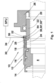
- the sensor ring 32 provided with a radial seal 40 and an axial sea 44, and it is assemble in sealed manner on the non-rotary slide ring carrier 22, as illustrated in Figure 2 .
- the sensor ring 32 is sealed in radial direction to the cylindrical part of the slide ring carrier 22 by means of at least one O-ring 40 provided at the inner circumference of the first wall 42 of the sensor ring 32 and in axial direction to the flange-like part 28, preferably but not necessarily, by means of an annular plane seal 44 provided on the outer surface of the second wall 46 of the sensor ring 32.
- the non-rotary slide ring carrier 22 is coupled, preferably in a non-rotary but, preferably but not necessarily, axially movable manner (possibly with the help of drive pins to keep the slide ring carrier 22 non-rotary and springs to allow axial movement of the non-rotary slide ring) to the gland ring 26 and the gland ring 26 is pushed inside an opening in the casing of a flow machine and fastened thereto.
- the rotary slide ring 18 and the non-rotary slide ring 24 fastened at an end of the non-rotary slide ring carrier 22 are brought in mechanical contact with one another.
- the sensor ring 32 illustrated, in addition to Figure 1 , also in Fig-ures 2, 3 and 4 is, in this embodiment of the present invention, provided with substantially axial holes 36 for fastening the sensor ring 32 to the flange-like part 28 of the non-rotary carrier ring 22, sensors 38, 48 required for watching at least one operating parameter of the mechanical seal and for monitoring the operation of the mechanical seal and a transmitting means 34 for transmitting the data measured by the sensors 38, 48, i.e. a so called measurement data, to the signal processing unit SPU.
- Sensor 38 may be a temperature, acoustic or vibration sensor, just to name a few optional alternatives without, however, limiting the present invention to the named alternatives.
- the sensor ring comprises an opening 50' which is arranged through the second wall 46 of the sensor ring 32.
- the openings are advantageously axial in respect to the carrier ring 22 and arranged coaxially with each other.
- Sensor 48 in Figures 3 and 4 is a pressure sensor configured to record the fluid pressure in front of the mechanical seal 10.
- the sensor 48 is provided in an opening 52 in the first wall 42 of the sensor ring 32.
- the temperature therein may be followed by means of the invention, just to name two optional alternatives without, however, limiting the present invention to the named alternatives only.
- the sensor ring 32 has a U-shaped cross section leaving between its first wall 42 and its second wall 46 such an internal cavity 54 within the sensor ring 32 that opens, when in use, radially inwardly towards the non-rotary slide ring carrier 22 so that the sensors 38 and 48, and especially the transmitting means, i.e. for instance a wiring thereof, may be arranged in the internal cavity 54 out of contact with the liquid surrounding the mechanical seal.
- the cavity 54 in the sensor ring 32 may be an annular cavity extending over the entire inner circumference of the sensor ring 32 or it may be formed of at least one groove machined or otherwise provided in the inner circumference of the sensor ring 32 to extend from the sensors 38, 48 to an opening 56 provided for taking the transmitting means 34 from the sensors out of the sensor ring 32.
- the opening 56 is arranged advantageously to extend radially through a bottom of the cavity 54.
- the transmitting means 34 when it is a mechanical wiring, a fibre optic cable or a set of wirings or cables, is preferably taken along a unitary channel to the signal processing unit SPU.
- the channel may be taken to the signal processing unit SPU through the gland ring 26 or through the bearing housing or the casing cover, i.e. through whichever machine element surrounding the mechanical seal.
Landscapes
- Engineering & Computer Science (AREA)
- General Engineering & Computer Science (AREA)
- Mechanical Engineering (AREA)
- Mechanical Sealing (AREA)
Claims (15)
- Sensorring zur Überwachung des Betriebs einer Gleitringdichtungsanordnung, wobei der Sensorring (32) eine erste Wand (42) und eine zweite Wand (46) und einen Hohlraum (54) dazwischen umfasst, wobei der Hohlraum (54) mindestens eine Nut umfasst, die im Innenumfang des Sensorrings (32) angeordnet ist und sich in radialer Richtung nach innen öffnet, dadurch gekennzeichnet, dass mindestens eine der ersten Wand (42) und der zweiten Wand (46) mindestens eine axiale Öffnung (50', 52) für mindestens einen Sensor (38, 48) umfasst.
- Sensorring nach Anspruch 1, dadurch gekennzeichnet, dass sich die mindestens eine Nut im Innenumfang des Sensorrings (32) von der mindestens einen Öffnung (50', 52) für mindestens einen Sensor (38, 48) zu einer Öffnung (56) erstreckt, die angeordnet ist, um sich radial durch einen Boden des Hohlraums (54) zu erstrecken.
- Sensorring nach Anspruch 2, dadurch gekennzeichnet, dass der Sensorring (32) eine erste Wand (42) und eine zweite Wand (46) aufweist, zwischen denen ein Hohlraum (54) verbleibt, wobei der Hohlraum (54) sich in einer radialen Richtung nach innen öffnet, und wobei mindestens eine Öffnung (50') in der zweiten Wand (46) angeordnet ist, durch die der mindestens eine Sensor (38) angeordnet werden kann, um sich von dem Hohlraum (54) nach ausserhalb des Sensorrings (32) zu erstrecken, wenn dieser zur Verwendung installiert ist.
- Sensorring nach Anspruch 1 oder 3, dadurch gekennzeichnet, dass der Hohlraum (54) im Sensorring (32) ein ringförmiger Hohlraum im Innenumfang des Sensorrings (32) ist.
- Sensorring nach Anspruch 3, gekennzeichnet durch Mittel (34) zum Übertragen der von dem mindestens einen Sensor (38, 48) gemessenen Daten zur weiteren Verarbeitung, wobei das Übertragungsmittel (34) eine Verdrahtung, ein Glasfaserkabel, eine HF-Verbindung oder eine Bluetooth-Verbindung ist.
- Gleitringdichtungsanordnung, wobei die Gleitringdichtungsanordnung (10) ein rotierendes Teil (12), ein nicht-rotierendes Teil (20) und eine Signalverarbeitungsanordnung (30) aufweist, wobei das rotierende Teil (12) mindestens einen rotierenden Gleitring (18) und einen rotierenden Gleitringträger (16) umfasst, wobei das nicht-rotierende Teil (20) mindestens einen nicht-rotierenden Gleitring (24) und einen nicht-rotierenden Gleitringträger (22) umfasst und wobei die Signalverarbeitungsanordnung (30) mindestens einen Sensor (38, 48) zur Überwachung des Betriebs der Gleitringdichtungsanordnung, einen mit dem mindestens einen Sensor (38, 48) versehenen Sensorring (32) und Mittel (34) zum Übertragen von Messdaten von dem mindestens einen Sensor (38, 48) zur weiteren Verarbeitung umfasst, dadurch gekennzeichnet, dass der Sensorring (32) ein Sensorring nach Anspruch 1 ist und dass der Sensorring (32) ein separates Ringelement ist, das an dem nicht-rotierenden Gleitringträger (22) angeordnet ist.
- Gleitringdichtungsanordnung nach Anspruch 6, dadurch gekennzeichnet, dass in der zweiten Wand (46) mindestens eine Öffnung (50') angeordnet ist, durch die der mindestens eine Sensor (38) angeordnet ist, um sich von dem Hohlraum (54) nach ausserhalb des Sensorrings (32) zu erstrecken.
- Gleitringdichtungsanordnung nach Anspruch 6, dadurch gekennzeichnet, dass im nicht-rotierenden Gleitringträger (22) mindestens eine Öffnung (50") für den mindestens einen Sensor (38) angeordnet ist.
- Gleitringdichtungsanordnung nach Anspruch 7, dadurch gekennzeichnet, dass die mindestens eine Öffnung (50') in der zweiten Wand (46) des Sensorrings (32) und die mindestens eine Öffnung (50") in dem nicht-rotierenden Gleitringträger (22) koaxial zueinander sind und sich zusammen von dem Hohlraum (54) zu dem nicht- rotierenden Gleitring (24) erstrecken, um den mindestens einen Sensor (38) in Kontakt mit dem nicht-rotierenden Gleitring (24) zu bringen.
- Gleitringdichtungsanordnung nach einem der Ansprüche 6 bis 8, dadurch gekennzeichnet, dass der Sensorring (32) an seiner ersten Wand (42) mindestens eine Öffnung (52) für mindestens einen Sensor (48) aufweist.
- Gleitringdichtungsanordnung nach Anspruch 9, dadurch gekennzeichnet, dass der mindestens eine Sensor (48) ein Drucksensor ist.
- Gleitringdichtungsanordnung nach einem der vorangehenden Ansprüche 6 bis 10, dadurch gekennzeichnet, dass der Hohlraum (54) im Sensorring (32) ein ringförmiger Hohlraum im Innenumfang des Sensorrings (32) ist.
- Gleitringdichtungsanordnung nach einem der vorangehenden Ansprüche 6 bis 10, dadurch gekennzeichnet, dass der Hohlraum (54) im Sensorring (32) mindestens eine Nut umfasst, die im Innenumfang des Sensorrings (32) angeordnet ist.
- Gleitringdichtungsanordnung nach einem der vorangehenden Ansprüche 6 bis 13, dadurch gekennzeichnet, dass der Sensorring (32) gegenüber dem nicht-rotierenden Gleitringträger (22) mittels mindestens eines O-Rings (40) und mindestens einer ringförmigen Flachdichtung (44) abgedichtet ist.
- Gleitringdichtungsanordnung nach Anspruch 6, dadurch gekennzeichnet, dass eine Signalverarbeitungseinheit (SPU) zum Empfangen der Messdaten des mindestens einen Sensors (38, 48) über die Übertragungsmittel (34) vorgesehen ist.
Applications Claiming Priority (2)
| Application Number | Priority Date | Filing Date | Title |
|---|---|---|---|
| EP19150289 | 2019-01-04 | ||
| PCT/EP2019/084664 WO2020141048A1 (en) | 2019-01-04 | 2019-12-11 | A mechanical sealing arrangement and a sensor ring for monitoring the operation of a mechanical seal arrangement |
Publications (2)
| Publication Number | Publication Date |
|---|---|
| EP3906372A1 EP3906372A1 (de) | 2021-11-10 |
| EP3906372B1 true EP3906372B1 (de) | 2025-05-14 |
Family
ID=65003202
Family Applications (1)
| Application Number | Title | Priority Date | Filing Date |
|---|---|---|---|
| EP19813911.5A Active EP3906372B1 (de) | 2019-01-04 | 2019-12-11 | Sensorring zur überwachung des betriebs einer mechanischen dichtungsanordnung |
Country Status (5)
| Country | Link |
|---|---|
| US (1) | US11965600B2 (de) |
| EP (1) | EP3906372B1 (de) |
| CN (1) | CN113423979B (de) |
| FI (1) | FI3906372T3 (de) |
| WO (1) | WO2020141048A1 (de) |
Families Citing this family (6)
| Publication number | Priority date | Publication date | Assignee | Title |
|---|---|---|---|---|
| BR122023003434B1 (pt) | 2016-02-23 | 2024-01-30 | John Crane Uk Ltd | Sistema de vedação mecânica configurado para detectar autonomamente uma perda de lubrificação dentro de uma interface de vedação deslizante de uma vedação mecânica, sistema de vedação mecânica que tem um subsistema de diagnóstico preditivo customizável configurado para ser adaptado para se adequar às necessidades individuais do onsumidor, condições ambientais particulares e/ou aplicações específicas, e sistema de vedação mecânica configurado para detectar condições de operação e fornecer avaliações de integridade em tempo real a um usuário durante a operação |
| US11280761B2 (en) | 2018-10-08 | 2022-03-22 | John Crane Uk Limited | Mechanical seal with sensor |
| EP3983704B1 (de) * | 2019-06-12 | 2023-11-29 | Sulzer Management AG | Verfahren zum betrieb eines dichtungsüberwachungssystems und dichtungsüberwachungssystem für eine dichtung |
| DE102020132453B4 (de) * | 2020-12-07 | 2023-02-02 | Eagleburgmann Germany Gmbh & Co. Kg | Gleitringdichtungsanordnung mit Detektion von Verschmutzung |
| CN116280147B (zh) * | 2023-04-28 | 2023-10-03 | 中国船舶科学研究中心 | 具有密封功能的半浸桨推进装置 |
| CN116989937B (zh) * | 2023-09-25 | 2023-12-22 | 苏州俊煌机械科技有限公司 | 一种机械密封件的检测方法及装置 |
Citations (1)
| Publication number | Priority date | Publication date | Assignee | Title |
|---|---|---|---|---|
| CN107100999B (zh) * | 2017-05-27 | 2018-07-03 | 李荣耀 | 镜油离心密封装置 |
Family Cites Families (20)
| Publication number | Priority date | Publication date | Assignee | Title |
|---|---|---|---|---|
| EP0454374B1 (de) * | 1990-04-23 | 1994-12-21 | Tanken Seiko Kabushiki Kaisha | Verfahren zur Vorhersage von Abweichungen in mechanischen Dichtungen und Gerät zu ihrer Vorhersage |
| US5104284A (en) * | 1990-12-17 | 1992-04-14 | Dresser-Rand Company | Thrust compensating apparatus |
| JP2681725B2 (ja) * | 1992-04-15 | 1997-11-26 | 株式会社タンケンシールセーコウ | メカニカルシールの挙動監視装置 |
| US5762342A (en) * | 1996-05-03 | 1998-06-09 | Durametallic Corporation | Mechanical seal with controller for regulating face contact pressure |
| DE59709157D1 (de) | 1997-07-31 | 2003-02-20 | Sulzer Pumpen Ag Winterthur | Verfahren zum Ueberwachen des Zustands einer mechanischen Dichtung |
| US6626436B2 (en) * | 1997-08-20 | 2003-09-30 | Crane John Inc | Monitoring seal system |
| US6360610B1 (en) | 1999-11-02 | 2002-03-26 | Jacek Jarzynski | Condition monitoring system and method for an interface |
| GB0224862D0 (en) * | 2002-10-25 | 2002-12-04 | Aesseal Plc | An intelligent sealing system |
| FI117300B (fi) * | 2005-04-29 | 2006-08-31 | Sulzer Pumpen Ag | Virtauskone, sen liukurengastiiviste, liukurengastiivisteen runkokappale ja menetelmä liukurengastiivisteen kiinnittämiseksi virtauskoneeseen |
| GB2430034A (en) | 2005-05-04 | 2007-03-14 | Aes Eng Ltd | A condition monitoring device using acoustic emission sensors and data storage devices. |
| DE102005036338A1 (de) * | 2005-07-29 | 2007-02-15 | Wilo Ag | Gleitringdichtung |
| CA2940397C (en) * | 2008-05-21 | 2018-11-20 | John Crane Inc. | Seal monitoring and control system |
| US8527214B2 (en) * | 2008-10-26 | 2013-09-03 | Michael N. Horak | System and method for monitoring mechanical seals |
| DE102010009194A1 (de) | 2010-02-24 | 2011-08-25 | KSB Aktiengesellschaft, 67227 | Gleitringdichtung und Verfahren zur Optimierung von deren Betriebsverhalten |
| JP6198636B2 (ja) | 2014-02-28 | 2017-09-20 | 日本ピラー工業株式会社 | 静圧形の非接触形メカニカルシール |
| BR122023003434B1 (pt) * | 2016-02-23 | 2024-01-30 | John Crane Uk Ltd | Sistema de vedação mecânica configurado para detectar autonomamente uma perda de lubrificação dentro de uma interface de vedação deslizante de uma vedação mecânica, sistema de vedação mecânica que tem um subsistema de diagnóstico preditivo customizável configurado para ser adaptado para se adequar às necessidades individuais do onsumidor, condições ambientais particulares e/ou aplicações específicas, e sistema de vedação mecânica configurado para detectar condições de operação e fornecer avaliações de integridade em tempo real a um usuário durante a operação |
| US10132412B2 (en) | 2016-08-05 | 2018-11-20 | Exxonmobil Upstream Research Company | Device and method for controlling rotating equipment seal without buffer support equipment |
| RU2718395C1 (ru) * | 2017-05-18 | 2020-04-02 | Зульцер Мэнэджмент Аг | Механическое уплотнение и его уплотнительное кольцо |
| EP3983704B1 (de) * | 2019-06-12 | 2023-11-29 | Sulzer Management AG | Verfahren zum betrieb eines dichtungsüberwachungssystems und dichtungsüberwachungssystem für eine dichtung |
| JP7221829B2 (ja) | 2019-08-21 | 2023-02-14 | 日立Geニュークリア・エナジー株式会社 | 状態監視システムおよび方法 |
-
2019
- 2019-12-11 FI FIEP19813911.5T patent/FI3906372T3/fi active
- 2019-12-11 WO PCT/EP2019/084664 patent/WO2020141048A1/en not_active Ceased
- 2019-12-11 CN CN201980084712.7A patent/CN113423979B/zh active Active
- 2019-12-11 EP EP19813911.5A patent/EP3906372B1/de active Active
- 2019-12-11 US US17/312,568 patent/US11965600B2/en active Active
Patent Citations (1)
| Publication number | Priority date | Publication date | Assignee | Title |
|---|---|---|---|---|
| CN107100999B (zh) * | 2017-05-27 | 2018-07-03 | 李荣耀 | 镜油离心密封装置 |
Also Published As
| Publication number | Publication date |
|---|---|
| US11965600B2 (en) | 2024-04-23 |
| CN113423979B (zh) | 2025-11-07 |
| WO2020141048A1 (en) | 2020-07-09 |
| EP3906372A1 (de) | 2021-11-10 |
| CN113423979A (zh) | 2021-09-21 |
| FI3906372T3 (fi) | 2025-08-14 |
| US20210324957A1 (en) | 2021-10-21 |
Similar Documents
| Publication | Publication Date | Title |
|---|---|---|
| EP3906372B1 (de) | Sensorring zur überwachung des betriebs einer mechanischen dichtungsanordnung | |
| AU2022259856B2 (en) | Systems and methods for predictive diagnostics for mechanical systems | |
| US6626436B2 (en) | Monitoring seal system | |
| EP2510264B1 (de) | Mit sensoren ausgestattete dichtungseinheit | |
| EP3625485B1 (de) | Mechanische dichtung und gleitring dafür | |
| EP3355043A1 (de) | Systeme und verfahren zur detektion eines durch ein fluid induzierten instabilitätszustands in einer turbomaschine | |
| EP3584472A1 (de) | Gleitringdichtungsanordnung für eine strömungsmaschine | |
| CN120265906A (zh) | 滑环密封组件 | |
| EP1290367A2 (de) | Vorrichtung zur überwachung einer dichtung | |
| US11892368B2 (en) | Condition monitoring apparatus | |
| US12163865B2 (en) | Detecting damage using an odor sensor | |
| JP2676654B2 (ja) | メカニカルシールの異常予知装置 | |
| GB2599700A (en) | A subsea pump and method for determining motion of the rotor | |
| CA3015495C (en) | Systems and methods for predictive diagnostics for mechanical systems | |
| JPH02204691A (ja) | ギアポンプ |
Legal Events
| Date | Code | Title | Description |
|---|---|---|---|
| STAA | Information on the status of an ep patent application or granted ep patent |
Free format text: STATUS: UNKNOWN |
|
| STAA | Information on the status of an ep patent application or granted ep patent |
Free format text: STATUS: THE INTERNATIONAL PUBLICATION HAS BEEN MADE |
|
| PUAI | Public reference made under article 153(3) epc to a published international application that has entered the european phase |
Free format text: ORIGINAL CODE: 0009012 |
|
| STAA | Information on the status of an ep patent application or granted ep patent |
Free format text: STATUS: REQUEST FOR EXAMINATION WAS MADE |
|
| 17P | Request for examination filed |
Effective date: 20210804 |
|
| AK | Designated contracting states |
Kind code of ref document: A1 Designated state(s): AL AT BE BG CH CY CZ DE DK EE ES FI FR GB GR HR HU IE IS IT LI LT LU LV MC MK MT NL NO PL PT RO RS SE SI SK SM TR |
|
| DAV | Request for validation of the european patent (deleted) | ||
| DAX | Request for extension of the european patent (deleted) | ||
| STAA | Information on the status of an ep patent application or granted ep patent |
Free format text: STATUS: EXAMINATION IS IN PROGRESS |
|
| 17Q | First examination report despatched |
Effective date: 20220530 |
|
| GRAP | Despatch of communication of intention to grant a patent |
Free format text: ORIGINAL CODE: EPIDOSNIGR1 |
|
| STAA | Information on the status of an ep patent application or granted ep patent |
Free format text: STATUS: GRANT OF PATENT IS INTENDED |
|
| INTG | Intention to grant announced |
Effective date: 20241022 |
|
| GRAJ | Information related to disapproval of communication of intention to grant by the applicant or resumption of examination proceedings by the epo deleted |
Free format text: ORIGINAL CODE: EPIDOSDIGR1 |
|
| STAA | Information on the status of an ep patent application or granted ep patent |
Free format text: STATUS: EXAMINATION IS IN PROGRESS |
|
| GRAP | Despatch of communication of intention to grant a patent |
Free format text: ORIGINAL CODE: EPIDOSNIGR1 |
|
| STAA | Information on the status of an ep patent application or granted ep patent |
Free format text: STATUS: GRANT OF PATENT IS INTENDED |
|
| INTC | Intention to grant announced (deleted) | ||
| INTG | Intention to grant announced |
Effective date: 20241204 |
|
| GRAS | Grant fee paid |
Free format text: ORIGINAL CODE: EPIDOSNIGR3 |
|
| GRAA | (expected) grant |
Free format text: ORIGINAL CODE: 0009210 |
|
| STAA | Information on the status of an ep patent application or granted ep patent |
Free format text: STATUS: THE PATENT HAS BEEN GRANTED |
|
| P01 | Opt-out of the competence of the unified patent court (upc) registered |
Free format text: CASE NUMBER: APP_13351/2025 Effective date: 20250318 |
|
| AK | Designated contracting states |
Kind code of ref document: B1 Designated state(s): AL AT BE BG CH CY CZ DE DK EE ES FI FR GB GR HR HU IE IS IT LI LT LU LV MC MK MT NL NO PL PT RO RS SE SI SK SM TR |
|
| REG | Reference to a national code |
Ref country code: GB Ref legal event code: FG4D |
|
| REG | Reference to a national code |
Ref country code: CH Ref legal event code: EP |
|
| REG | Reference to a national code |
Ref country code: DE Ref legal event code: R096 Ref document number: 602019070026 Country of ref document: DE |
|
| REG | Reference to a national code |
Ref country code: IE Ref legal event code: FG4D |
|
| REG | Reference to a national code |
Ref country code: SE Ref legal event code: TRGR |
|
| REG | Reference to a national code |
Ref country code: FI Ref legal event code: FGE |
|
| REG | Reference to a national code |
Ref country code: NL Ref legal event code: MP Effective date: 20250514 |
|
| PG25 | Lapsed in a contracting state [announced via postgrant information from national office to epo] |
Ref country code: PT Free format text: LAPSE BECAUSE OF FAILURE TO SUBMIT A TRANSLATION OF THE DESCRIPTION OR TO PAY THE FEE WITHIN THE PRESCRIBED TIME-LIMIT Effective date: 20250915 Ref country code: ES Free format text: LAPSE BECAUSE OF FAILURE TO SUBMIT A TRANSLATION OF THE DESCRIPTION OR TO PAY THE FEE WITHIN THE PRESCRIBED TIME-LIMIT Effective date: 20250514 |
|
| REG | Reference to a national code |
Ref country code: LT Ref legal event code: MG9D |
|
| PG25 | Lapsed in a contracting state [announced via postgrant information from national office to epo] |
Ref country code: NO Free format text: LAPSE BECAUSE OF FAILURE TO SUBMIT A TRANSLATION OF THE DESCRIPTION OR TO PAY THE FEE WITHIN THE PRESCRIBED TIME-LIMIT Effective date: 20250814 Ref country code: GR Free format text: LAPSE BECAUSE OF FAILURE TO SUBMIT A TRANSLATION OF THE DESCRIPTION OR TO PAY THE FEE WITHIN THE PRESCRIBED TIME-LIMIT Effective date: 20250815 |
|
| PG25 | Lapsed in a contracting state [announced via postgrant information from national office to epo] |
Ref country code: PL Free format text: LAPSE BECAUSE OF FAILURE TO SUBMIT A TRANSLATION OF THE DESCRIPTION OR TO PAY THE FEE WITHIN THE PRESCRIBED TIME-LIMIT Effective date: 20250514 Ref country code: NL Free format text: LAPSE BECAUSE OF FAILURE TO SUBMIT A TRANSLATION OF THE DESCRIPTION OR TO PAY THE FEE WITHIN THE PRESCRIBED TIME-LIMIT Effective date: 20250514 |
|
| PG25 | Lapsed in a contracting state [announced via postgrant information from national office to epo] |
Ref country code: BG Free format text: LAPSE BECAUSE OF FAILURE TO SUBMIT A TRANSLATION OF THE DESCRIPTION OR TO PAY THE FEE WITHIN THE PRESCRIBED TIME-LIMIT Effective date: 20250514 |
|
| PG25 | Lapsed in a contracting state [announced via postgrant information from national office to epo] |
Ref country code: HR Free format text: LAPSE BECAUSE OF FAILURE TO SUBMIT A TRANSLATION OF THE DESCRIPTION OR TO PAY THE FEE WITHIN THE PRESCRIBED TIME-LIMIT Effective date: 20250514 |
|
| PG25 | Lapsed in a contracting state [announced via postgrant information from national office to epo] |
Ref country code: RS Free format text: LAPSE BECAUSE OF FAILURE TO SUBMIT A TRANSLATION OF THE DESCRIPTION OR TO PAY THE FEE WITHIN THE PRESCRIBED TIME-LIMIT Effective date: 20250814 |
|
| PG25 | Lapsed in a contracting state [announced via postgrant information from national office to epo] |
Ref country code: IS Free format text: LAPSE BECAUSE OF FAILURE TO SUBMIT A TRANSLATION OF THE DESCRIPTION OR TO PAY THE FEE WITHIN THE PRESCRIBED TIME-LIMIT Effective date: 20250914 |
|
| PG25 | Lapsed in a contracting state [announced via postgrant information from national office to epo] |
Ref country code: LV Free format text: LAPSE BECAUSE OF FAILURE TO SUBMIT A TRANSLATION OF THE DESCRIPTION OR TO PAY THE FEE WITHIN THE PRESCRIBED TIME-LIMIT Effective date: 20250514 |
|
| PGFP | Annual fee paid to national office [announced via postgrant information from national office to epo] |
Ref country code: DE Payment date: 20251211 Year of fee payment: 7 |
|
| PG25 | Lapsed in a contracting state [announced via postgrant information from national office to epo] |
Ref country code: DK Free format text: LAPSE BECAUSE OF FAILURE TO SUBMIT A TRANSLATION OF THE DESCRIPTION OR TO PAY THE FEE WITHIN THE PRESCRIBED TIME-LIMIT Effective date: 20250514 Ref country code: SM Free format text: LAPSE BECAUSE OF FAILURE TO SUBMIT A TRANSLATION OF THE DESCRIPTION OR TO PAY THE FEE WITHIN THE PRESCRIBED TIME-LIMIT Effective date: 20250514 |
|
| PGFP | Annual fee paid to national office [announced via postgrant information from national office to epo] |
Ref country code: AT Payment date: 20251222 Year of fee payment: 7 |
|
| PGFP | Annual fee paid to national office [announced via postgrant information from national office to epo] |
Ref country code: FI Payment date: 20251224 Year of fee payment: 7 |
|
| PGFP | Annual fee paid to national office [announced via postgrant information from national office to epo] |
Ref country code: FR Payment date: 20251229 Year of fee payment: 7 |
|
| PGFP | Annual fee paid to national office [announced via postgrant information from national office to epo] |
Ref country code: BE Payment date: 20251219 Year of fee payment: 7 |
|
| PGFP | Annual fee paid to national office [announced via postgrant information from national office to epo] |
Ref country code: SE Payment date: 20251219 Year of fee payment: 7 |
|
| PG25 | Lapsed in a contracting state [announced via postgrant information from national office to epo] |
Ref country code: CZ Free format text: LAPSE BECAUSE OF FAILURE TO SUBMIT A TRANSLATION OF THE DESCRIPTION OR TO PAY THE FEE WITHIN THE PRESCRIBED TIME-LIMIT Effective date: 20250514 |
|
| PG25 | Lapsed in a contracting state [announced via postgrant information from national office to epo] |
Ref country code: EE Free format text: LAPSE BECAUSE OF FAILURE TO SUBMIT A TRANSLATION OF THE DESCRIPTION OR TO PAY THE FEE WITHIN THE PRESCRIBED TIME-LIMIT Effective date: 20250514 |
|
| PG25 | Lapsed in a contracting state [announced via postgrant information from national office to epo] |
Ref country code: SK Free format text: LAPSE BECAUSE OF FAILURE TO SUBMIT A TRANSLATION OF THE DESCRIPTION OR TO PAY THE FEE WITHIN THE PRESCRIBED TIME-LIMIT Effective date: 20250514 Ref country code: RO Free format text: LAPSE BECAUSE OF FAILURE TO SUBMIT A TRANSLATION OF THE DESCRIPTION OR TO PAY THE FEE WITHIN THE PRESCRIBED TIME-LIMIT Effective date: 20250514 |
|
| PG25 | Lapsed in a contracting state [announced via postgrant information from national office to epo] |
Ref country code: IT Free format text: LAPSE BECAUSE OF FAILURE TO SUBMIT A TRANSLATION OF THE DESCRIPTION OR TO PAY THE FEE WITHIN THE PRESCRIBED TIME-LIMIT Effective date: 20250514 |
|
| REG | Reference to a national code |
Ref country code: DE Ref legal event code: R097 Ref document number: 602019070026 Country of ref document: DE |
|
| PLBE | No opposition filed within time limit |
Free format text: ORIGINAL CODE: 0009261 |
|
| STAA | Information on the status of an ep patent application or granted ep patent |
Free format text: STATUS: NO OPPOSITION FILED WITHIN TIME LIMIT |
|
| REG | Reference to a national code |
Ref country code: CH Ref legal event code: L10 Free format text: ST27 STATUS EVENT CODE: U-0-0-L10-L00 (AS PROVIDED BY THE NATIONAL OFFICE) Effective date: 20260325 |
|
| 26N | No opposition filed |
Effective date: 20260217 |