EP3906333B1 - Verfahren zum weben von textilartikeln und vorrichtung zur durchführung des verfahrens - Google Patents
Verfahren zum weben von textilartikeln und vorrichtung zur durchführung des verfahrens Download PDFInfo
- Publication number
- EP3906333B1 EP3906333B1 EP19848799.3A EP19848799A EP3906333B1 EP 3906333 B1 EP3906333 B1 EP 3906333B1 EP 19848799 A EP19848799 A EP 19848799A EP 3906333 B1 EP3906333 B1 EP 3906333B1
- Authority
- EP
- European Patent Office
- Prior art keywords
- winding
- thread
- type element
- segments
- segment
- Prior art date
- Legal status (The legal status is an assumption and is not a legal conclusion. Google has not performed a legal analysis and makes no representation as to the accuracy of the status listed.)
- Active
Links
Images




Classifications
-
- D—TEXTILES; PAPER
- D03—WEAVING
- D03D—WOVEN FABRICS; METHODS OF WEAVING; LOOMS
- D03D41/00—Looms not otherwise provided for, e.g. for weaving chenille yarn; Details peculiar to these looms
-
- D—TEXTILES; PAPER
- D03—WEAVING
- D03D—WOVEN FABRICS; METHODS OF WEAVING; LOOMS
- D03D25/00—Woven fabrics not otherwise provided for
-
- D—TEXTILES; PAPER
- D03—WEAVING
- D03D—WOVEN FABRICS; METHODS OF WEAVING; LOOMS
- D03D25/00—Woven fabrics not otherwise provided for
- D03D25/005—Three-dimensional woven fabrics
-
- D—TEXTILES; PAPER
- D03—WEAVING
- D03D—WOVEN FABRICS; METHODS OF WEAVING; LOOMS
- D03D41/00—Looms not otherwise provided for, e.g. for weaving chenille yarn; Details peculiar to these looms
- D03D41/004—Looms for three-dimensional fabrics
Definitions
- the invention relates generally to the field of weaving. More particularly, the present invention relates to a device for manufacturing a textile article from a continuous wire element, a method for manufacturing said textile article and a textile article obtained by said method.
- the conventional textile industry is based on the mass production of articles which are woven, cut and then assembled according to known methods.
- textile design usually does not take into account the (three-dimensional) silhouette of the garment or the intention of the garment or customer expectation.
- the craft of custom-made clothing still exists.
- the traditional steps in making a custom-made garment are: the pattern, which consists of making the designs of a garment, the cutting of the fabric, which consists of cutting out all the pieces of the pattern, and the assembly, which consists of assembling the different pieces of fabric that are sewn.
- the present invention aims to overcome the drawbacks of traditional methods and devices for making a custom-made garment by proposing a new semi-automatic or automatic method for making a custom-made garment without any fabric waste.
- the present invention aims in particular to simplify the manufacture of a custom-made garment and thus reduce its cost by proposing a mechatronic manufacturing method of a textile or fabric with an openwork structure from a continuous thread. Said manufacturing method is implemented using a new weaving device.
- the weaving method corresponds to a technique using the interweaving of a continuous thread.
- the term "threaded element” means a thread chosen from the group consisting of a polyester thread, wool, cotton, pearl cotton, embroidery cotton, Scottish cotton, nylon, natural or synthetic raffia, string, more generally any thread of any nature that accepts tensioning, for example any thread used in textile knitting and weaving, including technical threads used in high mechanical performance components, including geotextiles.
- wire element segment means the portion of the wire element between two winding segments.
- winding segment means any means positioned vertically on a support allowing the winding of a wire element.
- the winding segments are chosen from the group consisting of pins, pegs, solid or hollow rods.
- the present invention therefore has as its first object a weaving device for the manufacture of a section of a textile article from a continuous wire element according to claim 1.
- the means capable of positioning or removing winding segments on the support is a removable or retractable winding segment planting/gripping head (3) provided with a clamp for planting/gripping the winding segments.
- the means (3) also comprises a linear actuator provided with a mechanism with 3 degrees of freedom for moving the planting/gripping head in three dimensions along the "X", "Y” and “Z” axes in a rectangular coordinate system and also along 2 angular axes alpha and beta for orienting and positioning the winding segments.
- the means (4) capable of delivering and winding the wire element around the winding segments is a removable or retractable distribution head (4) adjustable in height provided with an outlet for the wire element.
- the output of the wire element is in the form of a tube.
- the wire element is blocked on a first winding segment and then the tension of the wire element is ensured by a tension block upstream of the distribution head (4) of the wire element.
- the tension of the wire element is maintained by means of the tension system during the movement of the distribution head (4) of the wire element.
- the tension of the wire element is constant between the last passage point and the tension block.
- the device for varying the length and/or tension of the wire element of the present invention comprises a sensor for measuring tension, a control unit and a length and/or tension variation unit for unwinding the wire element under tension.
- the tension sensor is placed between the tension unit and the end piece located at the end of the tube of the wire element of the distribution head of the wire element to measure and/or adjust, using the control unit, the tension of the wire element according to the area to be woven defined by a person skilled in the art.
- the device according to the present invention comprises a support capable of receiving the winding segments.
- the support is in the form of a frame (13) whose orientation is adjustable through 90° to provide a working surface vertically or horizontally or inclined relative to the ground.
- the support is in the form of a frame with a length of 200 to 100 cm and a width of 150 to 80 cm, preferably a frame of 120 x 90 cm, 150 x 90 cm or 180 x 90 cm.
- the support is in the form of a table whose horizontal support is at a height from the ground of 75 to 95 cm, or whose vertical support has a base at a height from the ground of 60 to 80 cm.
- the support comprises or consists of one or more layers, of one or more materials. More particularly, the support comprises or consists of a part made of cork or shape memory or foam.
- the support further comprises a grid or a grid provided with markers or holes useful for locating and positioning the winding segments on said support.
- the support optionally comprises openings/orifices placed in the upper part of said support to allow the passage or placement of the winding segments.
- the support comprises or consists of a flat surface or comprises convex surfaces produced by series of intersecting profiles. These profiles have cutouts. By varying the orientation and distance of the profiles, it is thus possible to reproduce a large number of surfaces that are always convex, satisfying the objective of tensioning and shaping the wire, other than when the wire runs along the flat surface of the initial support.
- the convex surface is obtained by this network of intersecting profiles, preferably at 90°, which are fixed at their bases to the flat surface of the initial support.
- profile may refer to the vocabulary of an aerodynamic element, comprising a rounded leading edge, a maximum thickness placed towards the front third, and a thin trailing edge on the rear. The distance from the leading edge to the trailing edge is called the chord.
- a profile according to the invention refers for example to the following shapes: an airplane wing, a sail of a ship, a blade of a boomerang, a rudder, a keel, a rudder of a sailboat, a propeller of an airplane, a rotor of a helicopter.
- Each profile can vary in cutting. It meets, perpendicularly, every 5 to 10 cm another profile.
- the height can vary throughout the profile but remains similar at the intersection between two profiles. It is thus advantageous to have a set of profiles allowing the construction of a wide variety of totally or partially convex surface shapes.
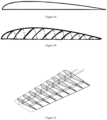
- a repetition of symmetrical profile intersections can constitute a wing as shown in figure 5 .
- Profiles can also be flat, hollow, multi-curved and asymmetrical.
- illet refers to the pattern marking the termination of an arcuate molding outline used to soften the contours of a cabinetwork piece. According to the present invention the term “fillet” is used to characterize the shape of a base of a profile.
- chamfer which is a particular fillet, constituting a small oblique, flat and regular surface, which is obtained by cutting down a sharp edge. Its value can be quantified by giving its inclination and its width: for example, we say “cut down the edges with a 3 mm chamfer at 45°”.
- the support comprises a frame (13) resting on the support.
- the frame is preferably made up of linear slides which may include linear guide units composed of a rail-carriage system, a ball shaft-sleeve system, or a rail-rail system with intermediate linear roller or ball cages.
- the linear guide units with drive are complete systems with one or more axes with a mechanical guide system, an electric motor and with a control adapted to the system.
- the guide units are chosen from the group consisting of ball guides, on profiled rails, by rollers, with recirculating ball runners, and precision guide rails.
- the guide units make it possible to combine a linear movement and a rotary movement.
- the support comprises a vibrating bowl (14) allowing the storage, distribution, and orientation of the winding segments, in particular the pins.
- the vibrating bowl according to the invention makes it possible to feed the device with pins automatically.
- This distribution system brings and directs the pins, stored in bulk in a tank, towards a motorized rotating plate provided with vertical storage locations for the pins, preferably from 5 to 30 vertical storage locations for the winding segments, for example pins which are picked up by a planting/gripping clamp.
- the vibrating bowl is provided with a chute or any other means, for example a pipe, which channels the fall of the pins at the point of arrival of the rotating plate, towards the vertical storage locations.
- a pin arrival detector makes it possible to trigger the rotation of the rotating plate.
- the winding segments (2) consist of or comprise elongated elements capable of holding the textile article being manufactured in a fixed position on the support.
- the winding segments consist of or comprise a metal, an alloy, wood, plastic, or ceramic.
- the winding segments are chosen from the group consisting of pins, pegs, solid or hollow rods.
- glue can be applied to the internal wire windings in contact with the body of the winding segment.
- the winding segments are smooth or are provided with roughness.
- the winding segments are provided with or without a head.
- the winding segments are covered with a sleeve made of rubber or another rough material and/or deformable under pressure to prevent the wire element from slipping out of the winding segment.
- the winding segments are arranged at an angle of 90 to 120° relative to the surface of the support.
- the height of the winding segments is dictated by the size and complexity of the textile article to be made.
- the height of the winding segments will be greater as the number of passes (windings) on each winding segment is important.
- the height of a winding segment for example a pin, is between 0.5 cm and 5 cm.
- the diameter of a winding segment is generally between 1 and 5 mm, preferably 2, 3, or 4 mm.
- the distance between two contiguous winding segments, implanted on the support is between 2 mm and 1 cm, preferably this distance is 5 mm.
- the winding segments are arranged on a part of the support equipped with a jack or any other lifting system or disengagement mechanism.
- the winding segments are arranged manually on the support.
- the winding segments are placed on the support using a means (3) provided with a clamp (11) for positioning or removing winding segments on the support according to the outline of a shape to be manufactured corresponding to the pattern of a textile article.
- Said means (3), in particular a head for planting/gripping the winding segments is optionally fixed on an articulated arm controlled by a computer system.
- Mecha-electronic means (5) for example stepper motors are used to move the planting/gripping head in three dimensions along the "X", "Y” and “Z" axes in a rectangular coordinate system as well as a system of 2 angular axes alpha and beta according to a predetermined sequence and pattern.
- the device according to the present invention comprises independent parts which are easily replaceable, particularly in the event of wear.
- the device of the present invention comprises a planting/gripping head (3) for arranging the winding segments on the support.
- the means (3) in particular the planting/gripping head, is movable in a plane that generally corresponds to an orthogonal X-Y plane.
- the device of the present invention further comprises a control unit configured to continuously coordinate the movements of the planting/gripping head (3) in the X-Y plane relative to the support.
- control unit means the software integrated or connected to the weaving device.
- the control unit is also configured to control the movement of the planting/gripping head (3) in the Z direction and on the alpha and beta rotations.
- the control unit comprises a digital input for loading an image (the pattern) of the textile article to be manufactured.
- the image (pattern) of the textile article to be manufactured can be scanned with a LECTRA type scanner or directly with a camera incorporated into the machine.
- the image can then be processed using commercial software such as MATLAB ® ( "matrix laboratory ") developed by the company The MathWorks.
- MATLAB ® can be used to manipulate matrices, display curves and data, implement algorithms, and create user interfaces.
- the computerized control system also includes input acquisition and power output control interfaces, for example an chicken ® (Mega) card, associated with power stages, a Twincat ® (Beckhoff) or birds ® (Mega) electronic card for controlling the weaving device according to the invention.
- the planting/gripping head (3) of the device of the present invention further comprises an optical camera connected to the control unit for scanning a pattern via the control unit.
- the camera also makes it possible to monitor the quality and manufacturing defects in real time and record the directions of the wire element segments during the manufacture of a textile panel according to the invention.
- the device of the present invention also comprises a wire element dispensing head (4) provided with a wire element outlet.
- the device of the present invention is designed so as to be able to substitute said dispensing head (4) for said planting/gripping head (3).
- the device of the present invention comprises said dispensing head (4) for winding the wire element around the winding segments arranged on the support.
- the dispensing head (4) is movable in a plane that generally corresponds to an orthogonal X-Y plane.
- the device of the present invention further comprises a control unit configured to continuously coordinate the movements of the dispensing head (4) in the X-Y plane relative to the support.
- control unit means the software integrated or connected to the weaving device.
- the control unit is also configured to control the movement of the dispensing head (4) in the Z direction and can optionally control the rotation of the dispensing head (4) about the Z axis.
- the control unit comprises a digital input for loading an image (the pattern) of the textile article to be manufactured.
- the dispensing head is controllably elevated along a "Z" axis in order to arrange the winding segments, for example on a three-dimensional support and optionally in order to sequentially form stretches and windings of the yarn around the winding segments arranged on the support.
- drive motors are provided to selectively move the dispensing head (4) in a predetermined pattern along the "X" and "Y" axes during the dispensing of the wire element.
- a relative vertical movement along a "Z" axis can also be performed during the formation of each winding, to allow the winding and tensioning of the wire element segments around the winding segments.
- the number of windings around the winding segments and the intersecting of the wire segments, and especially their directions can be programmed.
- These mechanical movements are preferably carried out by means of control signals input to the drive motors and the dispensing head from a CAD/CAM system.
- the design of a textile article to be manufactured is initially created from computer-aided design (CAD) software known to those skilled in the art; such software being used to convert the pattern shape into computer data retrievable in the form of wire element segments and needle placement as control signals via a computer-aided machine to the aforementioned drive motors.
- CAD computer-aided design
- the operator may disengage the automatic system of the device of the present invention in order to correct or reorient the manufacture of a textile article to create, for example, areas with complex openwork structures by modifying the number of windings around certain winding segments and interweavings of the wire segments, as programmed.
- the wire element at the base of the textile article to be manufactured is preferably supplied to the dispensing head (4) by a power source, such as a wire element spool.
- a separate mechanical drive means is provided for the vertical up and down movement of the dispensing head (4).
- a drive motor provides rotary drive power to a drive screw. Selected actuation of the motor rotates the screw to provide vertical up and down movement of the dispensing head (4) on the plain bearing.
- the motor is preferably a stepper motor, optionally with high resolution. It should be noted, however, that different types of motors could be used for the drive motors, including stepper motors, linear motors, servo motors, synchronous motors, DC motors and fluid motors.
- the motor (5a) allows the movement of at least one means (3) and/or (4) along the “X” axis
- the motor (5b) allows the movement of at least one means (3) and/or (4) along the “Y” axis
- the motor (5c) allows the movement of at least one means (3) and/or (4) along the “Y” axis.
- the manufacture of a textile article is carried out by the successive formation of segments of wire element around the winding segments forming the pattern of the textile article to be produced.
- the wire element feed is controlled relative to the "X", "Y” and "Z" movement of the distribution head so that the wire tension is controlled
- the coil of the wire element and its base are arranged in connection with the distribution head.
- the coil of the wire element rests on a base which is not integral with the device.
- the coil of the wire element can also rest on the ground.
- weaving device according to the invention can be used in an automatic or semi-automatic mode.
- Another subject of the present invention is a method of manufacturing a section of a textile article from a continuous wire element according to claim 7.
- Each segment of a wire element is by nature reversible so as to make it possible to modify the design formed by the tracing of the paths of the wire element. Once this shape has been validated, the winding of the wire element between two winding segments is made irreversible either by fixing (blocking) or by a closed loop (half key).
- the type of winding is selected from the group consisting of partial winding, total winding of the open loop type (reversible), total winding of the open loop type (made irreversible by fixing (blocking) a glue segment), complete winding of the blocked closed loop type (half hitch).
- partial winding total winding of the open loop type (reversible)
- total winding of the open loop type made irreversible by fixing (blocking) a glue segment
- complete winding of the blocked closed loop type half hitch.
- each segment of wire element positioned between two winding segments, is irreversibly fixed after validation of the tracing of the paths of the wire element on each of the winding segments, and so that the breakage of a segment of wire element has no impact on the other segments of wire element.
- said method further comprises positioning winding segments forming an outline, within the shape of the panel of a textile article to be manufactured within the shape to be manufactured.
- the step of stretching the wire element causes tension on the winding segment which can change the angle of the winding segment with the support.
- step a) of the method the positioning of the winding segments is carried out by any electromagnetic or mechatronic means such as a robotic arm controlled from an automatic or semi-automatic system.
- step a) of the method the positioning of the winding segments is defined by coordinates in an orthonormal reference frame.
- the winding segments can be implanted on a plane, or be contained and in reserve in this plane, protruding out of the support only on demand (manually, semi or completely automatically) or moving laterally on a rail-type segment comprising the winding segments movable in translation.
- said method comprises a step of locking each loop formed on each winding segment after the winding step.
- said method further comprises a step of blocking each wire segment performed after the step of winding the wire element around a winding segment.
- the step winding comprises forming at least a partial winding of the wire element around a winding segment.
- said blocking of at least one loop is formed on each winding segment after the winding step.
- said blocking is formed on all the loops of the panel of a textile article to be manufactured.
- said blocking of at least one loop on a winding segment is carried out by mechanical, chemical or thermal means, for example the blocking is carried out by means of a knot, a sewing or weaving segment, a staple, thread, glue, resin, welding, by folding a metal wire into a jumper once each of the two legs thereof has passed through each of the two partial or total windings of the wire element.
- the blocking can be done by trapping a thread other than the single continuous thread element used for the manufacture of a piece of textile according to the method of the present invention, forming a so-called "buttonhole" segment.
- said blocking is formed on all the loops of the panel of a textile article to be manufactured using one or more mechanical, chemical or thermal means.
- the welding can only be suitable for thermoplastic yarn types.
- the welding can be done with or without the addition of material. It consists of punctually heating the parts to be "glued” together by changing their state from solid to viscous, by heat, then pressing mechanically and waiting for the return to the solid state by lowering the temperature.
- said method comprises a step of winding the yarn onto two neighboring blocking points.
- This winding of the yarn onto two neighboring blocking points preferably comprises a blocking step by loop formed on one or both of the winding points, after the winding step.
- the direction of the wire element to form a wire element segment, positioned between two winding segments is chosen randomly or planned (designed and shown in drawing), semi-automatically or programmed, in this case by means of software), said direction involving
- control unit comprises a digital input for loading an image (the pattern) of the textile article to be manufactured, said digitized image comprising information on color, shape, size and covering density of the segments of the wire element.
- loading the digitized image into the control unit is accomplished by means of a digitizing tool such as a scanner.
- the digitized image is represented as a network representing the segments of the wireframe element.
- the weaving device comprises a computer on which is installed software known in the state of the art to control said device, in particular the different motors actuating the means (3-4) of the device.
- the computer may comprise a processing and control module connected to the weaving device.
- the device may also comprise a set of input peripherals connected (wired or wireless) to the computer, manipulable by an operator in order to produce the panel of textile by interacting with the software.
- the computer, the known software and the input peripherals constitute the means for creating the textile panel, and that the processing and control unit of the computer and the device of the present invention constitute the weaving means.
- the wire element may be positioned manually or automatically, around each winding segment, like a simple weave.
- the wire element makes back and forth paths between the winding segments of the panel of a textile article to be manufactured; each winding segment accepts up to 50 passes of the wire element, preferably more than 20 passes or 20 to 30 passes.
- the wire element required for weaving can vary in quality and thickness.
- the wire element is tensioned before being wound around a winding segment.
- the tension of the wire element is controlled by unwinding at least one spool associated with a motor for driving (in rotation) said spool, which motor is associated with a brake mechanism.
- the number of superpositions of wire element segments within the textile article being manufactured is tracked by an optical capture system, for example a camera.
- the method makes it possible to obtain a panel of textile article whose areas not covered by a segment of wire element have an average surface area of from 0.01 to 1 cm 2 .
- the textile article panel obtainable by said method comprises or is made of a single piece having a complex shape whose perimeter comprises both at least one curve and one straight line.
- the textile article panel obtainable by said method comprises or is made of a single piece having a complex shape whose perimeter comprises both at least one curve and one straight line.
- the textile article panel obtainable by said method comprises or consists of a single piece of rounded or convex shape, forming a three-dimensional article.
- the textile article panel obtainable by said method comprises or consists of at least one thickness, i.e. a single superposition of wire element.
- the loops forming the perimeter of each panel of textile article obtainable by said method are linked together by buttonhole stitches.
- the textile article panel obtainable by said method is assembled into a garment, a covering or covering fabric for an object, industrial furniture such as a car seat, a locker room accessory, a shoe, a component of technical equipment such as an explosion-proof tank, a propeller blade of a wind turbine for example.
- several panels of textile article obtainable by a method according to the invention are assembled into a garment, a covering or covering fabric of an object, industrial furniture, a locker room accessory, a shoe, or a component of technical equipment.
- Said assembly of several panels of textile article can be carried out by means of one or more buttonhole stitches assembling the panels of textile article edge to edge without superposition.
- the present invention also relates to an assembly of several panels of textile article obtainable by a method according to the invention, characterized in that said assembly is carried out by means of one or more buttonhole stitches assembling the panels of textile article edge to edge without superposition, as shown in the figure. figure 7 .
- the present invention also relates to a tailor-made garment comprising several panels of textile article obtainable by a method according to the invention, characterized in that said panels of textile article are assembled by means of one or more buttonhole stitches assembling the panels of textile article edge to edge without superposition.
- a custom-made garment corresponds to a garment whose body measurements have been previously digitized in order to be processed by computer-aided design (CAD) software known to those skilled in the art.
- CAD computer-aided design
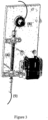
- FIG. 1 is a perspective view showing the device for placing the winding segments on the support.
- FIG. 2 is a general view of the planting/gripping head (3) of the winding segments.
- FIG. 3 is a general view of the distribution head (4).
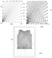
- FIG 4 is a diagram showing the arrangement of winding segments and multiple wire segments wound x times (18 times on the Figure 4a ) on the same winding segment; the Figure 4b shows the textile being manufactured.
- the figure 4c represents a section of textile article obtained or in the process of being obtained by the process.
- FIG. 5 represents a planar profile (in section) (5a), a 3D shape made from a profile (5b) and a repetition of profiles forming a wing (5c).
- FIG. 6A represents a photograph of a vibrating bowl
- the Figure 6B represents a diagram of the operating principle of the downgrading of the winding segments (pins)
- step 1 represents the exit point one by one of the pins, oriented head upwards
- step 2 represents the descent of the pins by gravity
- step 3 represents the detection of the arrival of the pins
- step 4 represents the rotation or stopping of the turntable depending on its state of loading with pins
- step 5 represents the unloading of the turntable by the gripping clamp of the device of the invention.
- FIG. 7 A shows the finishing of two pieces of textile obtained according to the invention using a buttonhole stitch.
- FIG. 7B represents the assembly of two pieces of textile obtained according to the invention.
- the assembly shows 3 buttonhole stitches side by side.
- FIG. 7C represents a close-up photograph of the finishing of a section of textile article according to the invention.
- the weaving directions i.e. the orientations of the wire element segments around the winding segments
- the positions of the wire element segments are recorded by the control system via a camera of the type (5MP OmniVision ® OV5640 without distortion).
- This operating mode is particularly advantageous when the operator wishes to create several identical or substantially identical textile pieces, i.e. comprising the same weaving directions.
- the previously defined weaving characteristics can be converted into computer data. Modifications can be provided to define variations in the orientation of the wire element segments in order to obtain a textile panel having the same or substantially identical shape but whose aesthetic appearance and/or weaving characteristics and/or are different.
- a surface of the support has been represented on the figure 4 ; said surface has 7 winding segments on a first vertical left axis, 7 other winding segments on a second vertical right axis and 10 winding segments on a “lower” horizontal axis.
- the figure 4 does not represent winding segments on a "higher” horizontal axis.
- FIG 4 it is understood that a succession of steps of winding the wire element is carried out around a first winding segment, on the original position at the intersection of the vertical left axis and the "lower" horizontal axis.
- This figure represents the formation of 18 wire element segments (12a-12r), all wound on a single winding segment. These 18 wire element segments are formed following a return path towards the first winding segment.
- the Figure 4b represents a weaving step in which a repetition of the steps of stretching and winding the wire element are carried out around all the winding segments of the form to be manufactured so as to form intersecting wire element segments.
- the thickness of the textile panel to be manufactured is a function of the number of passes made over each winding segment and the thickness of the wire element.
- FIG. 4c represents a section of a textile article being manufactured.
- the loops are always fixed on the winding segments of the weaving device according to the invention.
Landscapes
- Engineering & Computer Science (AREA)
- Textile Engineering (AREA)
- Treatment Of Fiber Materials (AREA)
- Woven Fabrics (AREA)
- Looms (AREA)
Claims (14)
- Webvorrichtung zur Herstellung einer Bahn eines Textilartikels aus einem Endlosfilament, wobei die Vorrichtung umfasst:- einen Träger (1), der eben ist, oder
eben ist und eine oder mehrere nicht ebene Zone(n), die vorzugsweise konvex ist(sind), umfasst oder von einer oder mehreren nicht ebenen Zone(n), die vorzugsweise konvex ist(sind), gebildet ist,- Wickelsegmente (2),- ein Mittel (3), das geeignet ist, Wickelsegmente auf dem Träger gemäß der Kontur einer herzustellenden Form entsprechend dem Schnittmuster des Textilartikels anzuordnen oder wegzunehmen,- ein Mittel (4), das geeignet ist, das Filament zuzuführen und um Wickelsegmente zu wickeln,- eine Filamentzuführung,- optional einen Sockel für eine oder mehrere Spule(n) eines Filaments (9),
wobei die Vorrichtung dadurch gekennzeichnet ist, dass- mechanisch-elektronische Mittel (5), um die Mittel (3), die geeignet sind, Wickelsegmente auf dem Träger anzuordnen oder wegzunehmen, und (4), die geeignet sind, das Filament zuzuführen und um Wickelsegmente in drei Dimensionen entlang der Achsen "X", "Y" und "Z" in einem rechteckigen Koordinatensystem sowie auf 2 Alpha- und Beta-Rotationsachsen in einem Winkelsystem gemäß einer vorbestimmten Folge und einem vorbestimmten Motiv zu wickeln, zu verlagern, und- ein Steuersystem, umfassend eine Software, die die Verlagerung des oder der Mittel (3), das(die) geeignet ist(sind), Wickelsegmente auf dem Träger anzuordnen oder wegzunehmen, und (4), die geeignet sind, das Filament zuzuführen und um Wickelsegmente zu wickeln, steuert, wodurch es möglich ist, die Wickelsegmente auf dem Träger anzuordnen und das Wickeln des Filaments um die Wickelsegmente durchzuführen. - Vorrichtung zur Herstellung einer Bahn eines Textilartikels nach Anspruch 1, dadurch gekennzeichnet, dassdas Mittel (3), das geeignet ist, Wickelsegmente (2) auf dem Träger (1) anzuordnen oder wegzunehmen, ein abnehmbarer oder einziehbarer Kopf zum Einsetzen/Ergreifen der Wickelsegmente (2) ist, der mit einer Zange zum Einsetzen/Ergreifen der Wickelsegmente (2) versehen ist, unddas Mittel (4), das geeignet ist, das Filament zuzuführen und um Wickelsegmente (2) zu wickeln, ein höhenverstellbarer abnehmbarer oder einziehbarer Verteilerkopf (4) ist der mit einem Ausgang für das Filament versehen ist.
- Vorrichtung zur Herstellung einer Bahn eines Textilartikels nach Anspruch 1 oder 2, dadurch gekennzeichnet, dass die Vorrichtung ferner Mittel zur Einstellung der Spannung (8) des Filaments umfasst.
- Vorrichtung zur Herstellung einer Bahn eines Textilartikels nach einem der Ansprüche 1 bis 3, dadurch gekennzeichnet, dass der Träger (1) geeignet ist, Wickelsegmente (2) aufzunehmen.
- Vorrichtung zur Herstellung einer Bahn eines Textilartikels nach Anspruch 4, dadurch gekennzeichnet, dass die Wickelsegmente (2) in der Gruppe, die von Nadeln, Stiften, massiven oder hohlen Stangen gebildet ist, ausgewählt sind.
- Vorrichtung zur Herstellung einer Bahn eines Textilartikels nach Anspruch 5, dadurch gekennzeichnet, dass die Wickelsegmente (2) glatt sind oder mit rauen Stellen versehen sind und optional mit einer Hülse aus Kautschuk oder einem anderen rauen und/oder bei Druck verformbaren Material überzogen sind, um zu verhindern, dass das Filament aus dem Wickelsegment (2) rutscht.
- Verfahren zur Herstellung einer Bahn eines Textilartikels aus einem Endlosfilament (9), umfassend:a) einen Schritt, der darin besteht, Wickelsegmente in einer Ausgangsposition auf einem Träger (1) anzuordnen, um die Kontur einer herzustellenden Form entsprechend dem Schnittmuster eines Textilartikels,b) einen Schritt des Wickelns des Filaments (9) um ein erstes Wickelsegment (2),c) einen Schritt des Ziehens des Filaments (9), um das Filament (9) um ein zweites Wickelsegment (2) zu wickeln und auf diese Weise ein erstes Filamentsegment (9) zu bilden,d) einen Schritt des Ziehens des um das zweite Wickelsegment (2) gewickelten Filaments (9) entweder entlang einer Strecke rückwärts zu dem ersten Wickelsegment (2) oder einer Strecke vorwärts zu einem weiteren Wickelsegment (2) und des Bildens eines zweiten Filamentsegments (9),e) eine Wiederholung der Schritte des Ziehens und Wickelns des Filaments (9) um alle Wickelsegmente (2) der Kontur der herzustellenden Form, um ein drittes, ein viertes, bis zum n-ten Filamentsegment (9) zu bilden, um die Textilartikelbahn zu erhalten,f) einen Schritt des Wegnehmens der hergestellten Textilartikelbahn von dem Träger (1), wobei die Wickelsegmente (2) durch jegliches Mittel zur vertikalen Translation von ihrer Ausgangsposition nach unten oder nach oben verlagert werden,
wobei das Verfahren dadurch gekennzeichnet ist, dassg) der Schritt a) des Verfahrens durch jegliches elektro-mechanische oder mechatronische Mittel durchgeführt wird, undwobei das Verfahren mit Hilfe der Webvorrichtung nach einem der Ansprüche 1 bis 6 verwirklicht wird. - Verfahren zur Herstellung einer Bahn eines Textilartikels nach Anspruch 7, dadurch gekennzeichnet, dass das Wickeln des Filaments (9) um alle Wickelsegmente (2) in der Gruppe ausgewählt ist, die von einem Teilwickeln, einem Totalwickeln des Typs reversible oder irreversible offene Schleife, und einem Komplettwickeln des Typs feste geschlossene Schleife gebildet ist.
- Verfahren zur Herstellung einer Bahn eines Textilartikels nach Anspruch 8, ferner umfassend einen Schritt des Befestigens jeder geschlossenen Schleife auf jedem Wickelsegment (2) nach dem Wickelschritt.
- Verfahren zur Herstellung einer Bahn eines Textilartikels nach Anspruch 9, dadurch gekennzeichnet, dass jedes Filamentsegment (9), das zwischen zwei Wickelsegmenten (2) angeordnet ist, irreversibel nach Freigab e des Verlaufs der Strecken des Filaments (9) auf jedem der Wickelsegmente (2) befestigt wird.
- Verfahren zur Herstellung einer Bahn eines Textilartikels nach Anspruch 9, dadurch gekennzeichnet, dass die Befestigung jeder Schleife auf einem Wickelsegment (2) durch ein mechanisches, chemisches oder thermisches Mittel erfolgt.
- Verfahren zur Herstellung einer Bahn eines Textilartikels nach Anspruch 7, dadurch gekennzeichnet, dass eine Richtung des Filaments (9), um ein Filamentsegment (9) zu bilden, das zwischen zwei Wickelsegmenten (2) angeordnet ist, zufällig oder geplant, manuell, halbautomatisch oder programmiert gewählt wird,wobei die Richtung entweder eine Hin- und Rückstrecke des Filaments (9) zwischen zwei Wickelsegmenten (2) impliziert, um eine Übereinanderlagerung von zwei Segmenten zwischen zwei oben erwähnten Wickelsegmenten (2) zu erhalten,oder eine Strecke des Filaments (9) zu einem anderen Wickelsegment (2) als jenem, das von der letzten Strecke des Filaments (9) stammt, impliziert, um ein teilweises oder schleifenförmiges Wickeln zwischen dem neuen Filamentsegment (9) mit einem oder mehreren bestehenden Segmenten zu erhalten.
- Anordnung mehrerer Bahnen eines Textilartikels, die durch ein Verfahren nach einem der Ansprüche 7 bis 12 erhalten werden, dadurch gekennzeichnet, dass die Anordnung einen oder mehrere Verbindungspunkte umfasst, die die Textilartikelbahnen Kante an Kante ohne Überlappung verbinden, wobei die Anordnung insbesondere ein Kleidungsstück, ein Gewebe zum Überziehen oder Abdecken eines Gegenstandes, ein Industriemöbel, ein Kleidungszubehör oder eine Komponente einer technischen Ausrüstung ist.
- Maßkleidungsstück, umfassend eine Anordnung mehrere Textilartikelbahnen nach Anspruch 13.
Applications Claiming Priority (2)
| Application Number | Priority Date | Filing Date | Title |
|---|---|---|---|
| FR1874416A FR3091300B1 (fr) | 2018-12-31 | 2018-12-31 | nouveau procédé de tissage d’articles textiles et dispositif pour la mise en oeuvre |
| PCT/FR2019/053218 WO2020141271A1 (fr) | 2018-12-31 | 2019-12-19 | Procede de tissage d'articles textiles et dispositif pour la mise en oeuvre |
Publications (3)
| Publication Number | Publication Date |
|---|---|
| EP3906333A1 EP3906333A1 (de) | 2021-11-10 |
| EP3906333C0 EP3906333C0 (de) | 2025-02-05 |
| EP3906333B1 true EP3906333B1 (de) | 2025-02-05 |
Family
ID=67262427
Family Applications (1)
| Application Number | Title | Priority Date | Filing Date |
|---|---|---|---|
| EP19848799.3A Active EP3906333B1 (de) | 2018-12-31 | 2019-12-19 | Verfahren zum weben von textilartikeln und vorrichtung zur durchführung des verfahrens |
Country Status (5)
| Country | Link |
|---|---|
| US (1) | US12215446B2 (de) |
| EP (1) | EP3906333B1 (de) |
| JP (1) | JP7398752B2 (de) |
| FR (1) | FR3091300B1 (de) |
| WO (1) | WO2020141271A1 (de) |
Families Citing this family (1)
| Publication number | Priority date | Publication date | Assignee | Title |
|---|---|---|---|---|
| US20250100129A1 (en) * | 2023-09-27 | 2025-03-27 | Purdue Research Foundation | Microrobot control system and method |
Family Cites Families (24)
| Publication number | Priority date | Publication date | Assignee | Title |
|---|---|---|---|---|
| US662963A (en) * | 1900-06-11 | 1900-12-04 | Edward Everard Preston | Fabric for jackets for pneumatic tires. |
| US2150937A (en) * | 1936-02-24 | 1939-03-21 | Raybestos Manhattan Inc | Clutch facing |
| US3039169A (en) * | 1955-10-12 | 1962-06-19 | Owens Corning Fiberglass Corp | Method and apparatus for forming cloth-like mats of oriented continuous strands |
| GB1157856A (en) * | 1966-05-10 | 1969-07-09 | Jarmuefejlesztesi Intezet | Improvements in or relating to the Production of Textile Materials |
| US3399642A (en) * | 1967-03-30 | 1968-09-03 | West Point Pepperell Inc | Process for preventing seam pucker |
| DE2545782C3 (de) * | 1975-10-13 | 1980-08-21 | Volker 8712 Volkach Friedrich | Verfahren und Vorrichtung zur Herstellung eines Diagonalgeleges |
| DE3003666A1 (de) * | 1980-02-01 | 1981-08-06 | Richard 4937 Lage Pott | Gelege zur herstellung einer verstaerkung von im wesentlichen aus flaechen bestehenden bauteilen und eine vorrichtung zur herstellung desselben |
| JPS58160209U (ja) * | 1982-04-15 | 1983-10-25 | ミドリ安全工業株式会社 | 静電気帯電防止用の被服 |
| US4715924A (en) * | 1982-11-29 | 1987-12-29 | E. I. Du Pont De Nemours And Company | Apparatus for forming a web |
| US4976012A (en) * | 1982-11-29 | 1990-12-11 | E. I Du Pont De Nemours And Company | Method of forming a web |
| USRE33418E (en) * | 1984-04-23 | 1990-11-06 | Jb Group, Inc. | Method and apparatus for production of bias fabrics |
| US4557790A (en) * | 1984-07-12 | 1985-12-10 | Cincinnati Milacron Inc. | Tape laminator |
| US4774108A (en) * | 1986-04-04 | 1988-09-27 | Cano Arq C C | Methods of forming and using mat to obtain surface finishes |
| DE4234083A1 (de) * | 1992-10-09 | 1994-04-14 | Olbo Textilwerke Gmbh | Verfahren und Vorrichtung zum Legen von Fäden |
| JP3556071B2 (ja) * | 1997-06-10 | 2004-08-18 | 株式会社エクセディ | クラッチフェーシング巻取り機 |
| US20030196743A1 (en) * | 2002-04-17 | 2003-10-23 | Vincent Borbone | Apparatus and methods for producing tow based patterns |
| FR2843758B1 (fr) * | 2002-08-22 | 2005-03-11 | Eads Launch Vehicles | Procede pour la realisation d'une preforme textile multidirectionnelle et piece en materiau composite incorporant ladite preforme |
| FR2869330B1 (fr) * | 2004-04-23 | 2006-07-21 | Messier Bugatti Sa | Procede de fabrication de nappe fibreuse bidimensionnelle helicoidale |
| US20060048262A1 (en) * | 2004-09-02 | 2006-03-09 | Jacqueline Sencion | Fashion concept |
| JP2006265771A (ja) * | 2005-03-24 | 2006-10-05 | Nisshinbo Ind Inc | 縫製品及び縫製品のシームパッカリング防止方法 |
| JP5029134B2 (ja) | 2007-05-15 | 2012-09-19 | 株式会社豊田自動織機 | 繊維束配列装置 |
| JP5411617B2 (ja) | 2009-08-04 | 2014-02-12 | ファナック株式会社 | 誤差補正手段を備えた数値制御装置 |
| WO2015066407A1 (en) * | 2013-10-31 | 2015-05-07 | United Technologies Corporation | A method for selective placement of reinforcing fibers in polymeric components |
| DE202017103295U1 (de) * | 2017-05-31 | 2017-07-05 | Petra Olczewski | Textiler Zuschnitt |
-
2018
- 2018-12-31 FR FR1874416A patent/FR3091300B1/fr active Active
-
2019
- 2019-12-19 JP JP2021538490A patent/JP7398752B2/ja active Active
- 2019-12-19 WO PCT/FR2019/053218 patent/WO2020141271A1/fr not_active Ceased
- 2019-12-19 US US17/419,663 patent/US12215446B2/en active Active
- 2019-12-19 EP EP19848799.3A patent/EP3906333B1/de active Active
Non-Patent Citations (1)
| Title |
|---|
| ANONYMOUS: "Second skin: fashion range, Clinique Vestimentaire - garments made entirely from one recycled thread & by hand by young French designer, Jeanne Vicerial.", 6 April 2016 (2016-04-06), pages 1 - 8, XP093042101, Retrieved from the Internet <URL:https://decanteddesign.com/2016/04/06/second-skin-fashion-range-clinique-vestimentaire-made-entirely-from-one-recycled-thread-by-hand-by-young-french-designer-jeanne-vicerial-see-blogroll-for-a-link-to-the-colourblind-site/> [retrieved on 20230425] * |
Also Published As
| Publication number | Publication date |
|---|---|
| FR3091300A1 (fr) | 2020-07-03 |
| US12215446B2 (en) | 2025-02-04 |
| JP7398752B2 (ja) | 2023-12-15 |
| FR3091300B1 (fr) | 2021-02-19 |
| EP3906333C0 (de) | 2025-02-05 |
| WO2020141271A1 (fr) | 2020-07-09 |
| EP3906333A1 (de) | 2021-11-10 |
| JP2022518365A (ja) | 2022-03-15 |
| US20220074088A1 (en) | 2022-03-10 |
Similar Documents
| Publication | Publication Date | Title |
|---|---|---|
| CA1319081C (fr) | Machine pour la mise en oeuvre d'un procede de fabrication d'elements d'armature composites tisses en trois dimensions, et produit obtenu | |
| CA2147040C (fr) | Procede et machine pour la realisation d'une armature pour une piece de matiere composite | |
| CA2089209C (fr) | Procede pour la realisation d'une armature de fibres pour piece de matiere composite, et piece composite comportant une telle armature | |
| EP0678610B1 (de) | Verfahren und Vorrichtung zur Herstellung einer Verstärkungsplatte für einen Teil Verbundmaterial | |
| CA2752032A1 (fr) | Procede et dispositif de fabrication automatisee d'au moins une piece allongee a une ou plusieurs couches en materiaux composites | |
| FR2587318A1 (fr) | Procede et machine pour la fabrication de pieces creuses de revolution formees de fils s'etendant selon trois directions differentes. | |
| EP3906333A1 (de) | Verfahren zum weben von textilartikeln und vorrichtung zur durchführung des verfahrens | |
| FR2719607A3 (fr) | Machine à tricoter circulaire. | |
| FR2541979A1 (fr) | Dispositif pour empiler des liasses de feuilles reliees | |
| EP0483101A1 (de) | Verfahren und Vorrichting zum Tuften | |
| FR3063673A1 (fr) | Plateforme mobile pour robot parallele a cables, robot parallele a cables, installation et procede de drapage a l'aide d'un tel robot | |
| FR2561631A1 (fr) | Procede et dispositif de prehension de couches souples en particulier textiles et machine pour la prehension et le transfert desdites couches | |
| FR2561677A1 (fr) | Machine pour la fabrication d'organes de structure par tressage et organes de structure obtenus | |
| FR2794775A1 (fr) | Appareil pour inserer un fil de liaison dans un tissu tridimensionnel | |
| CA2079626C (fr) | Procede et machine pour la realisation d'armatures fibreuses creuses | |
| FR2626201A1 (fr) | Support textile brode, procede de decoration d'un support textile et dispositif permettant la mise en oeuvre dudit procede | |
| EP0230803A1 (de) | Mehrschichtiger, textiler Gegenstand für die Herstellung von Schichtmaterialien, Verfahren und Vorrichtung zur Herstellung desselben | |
| EP1314541A1 (de) | Verfahren zur Schusslegung zur Herstellung eines dicken textilen Bewährungselements und danach erhaltenes Bewährungselement | |
| BE1003201A3 (fr) | Dispositif de couture pour coudre automatiquement un tissu possedant une forme rectiligne sur un tissu possedant une forme courbe. | |
| EP0226687A1 (de) | Verfahren zum Färben von Materialbahnen | |
| FR2630461A1 (fr) | Procede et dispositif d'alimentation automatique d'une machine a coudre | |
| FR2832739A1 (fr) | Procede de realisation d'une preforme textile multidirectionnelle, dispositif pour sa mise en oeuvre et preforme ainsi obtenue | |
| BE1003829A6 (fr) | Procede et dispositif de fabrication d'un tapis a points noues. | |
| FR3133558A1 (fr) | Procédé de fabrication d’un objet décoratif à partir d’au moins une couche de cordon extrudé. | |
| CA1323287C (fr) | Element d'armature composite tisse en trois dimensions |
Legal Events
| Date | Code | Title | Description |
|---|---|---|---|
| STAA | Information on the status of an ep patent application or granted ep patent |
Free format text: STATUS: UNKNOWN |
|
| STAA | Information on the status of an ep patent application or granted ep patent |
Free format text: STATUS: THE INTERNATIONAL PUBLICATION HAS BEEN MADE |
|
| PUAI | Public reference made under article 153(3) epc to a published international application that has entered the european phase |
Free format text: ORIGINAL CODE: 0009012 |
|
| STAA | Information on the status of an ep patent application or granted ep patent |
Free format text: STATUS: REQUEST FOR EXAMINATION WAS MADE |
|
| 17P | Request for examination filed |
Effective date: 20210630 |
|
| AK | Designated contracting states |
Kind code of ref document: A1 Designated state(s): AL AT BE BG CH CY CZ DE DK EE ES FI FR GB GR HR HU IE IS IT LI LT LU LV MC MK MT NL NO PL PT RO RS SE SI SK SM TR |
|
| DAV | Request for validation of the european patent (deleted) | ||
| DAX | Request for extension of the european patent (deleted) | ||
| STAA | Information on the status of an ep patent application or granted ep patent |
Free format text: STATUS: EXAMINATION IS IN PROGRESS |
|
| 17Q | First examination report despatched |
Effective date: 20230504 |
|
| GRAP | Despatch of communication of intention to grant a patent |
Free format text: ORIGINAL CODE: EPIDOSNIGR1 |
|
| STAA | Information on the status of an ep patent application or granted ep patent |
Free format text: STATUS: GRANT OF PATENT IS INTENDED |
|
| INTG | Intention to grant announced |
Effective date: 20241008 |
|
| GRAS | Grant fee paid |
Free format text: ORIGINAL CODE: EPIDOSNIGR3 |
|
| GRAA | (expected) grant |
Free format text: ORIGINAL CODE: 0009210 |
|
| STAA | Information on the status of an ep patent application or granted ep patent |
Free format text: STATUS: THE PATENT HAS BEEN GRANTED |
|
| AK | Designated contracting states |
Kind code of ref document: B1 Designated state(s): AL AT BE BG CH CY CZ DE DK EE ES FI FR GB GR HR HU IE IS IT LI LT LU LV MC MK MT NL NO PL PT RO RS SE SI SK SM TR |
|
| REG | Reference to a national code |
Ref country code: GB Ref legal event code: FG4D Free format text: NOT ENGLISH |
|
| REG | Reference to a national code |
Ref country code: CH Ref legal event code: EP |
|
| REG | Reference to a national code |
Ref country code: IE Ref legal event code: FG4D Free format text: LANGUAGE OF EP DOCUMENT: FRENCH |
|
| REG | Reference to a national code |
Ref country code: DE Ref legal event code: R096 Ref document number: 602019065648 Country of ref document: DE |
|
| U01 | Request for unitary effect filed |
Effective date: 20250217 |
|
| U07 | Unitary effect registered |
Designated state(s): AT BE BG DE DK EE FI FR IT LT LU LV MT NL PT RO SE SI Effective date: 20250221 |
|
| PG25 | Lapsed in a contracting state [announced via postgrant information from national office to epo] |
Ref country code: RS Free format text: LAPSE BECAUSE OF FAILURE TO SUBMIT A TRANSLATION OF THE DESCRIPTION OR TO PAY THE FEE WITHIN THE PRESCRIBED TIME-LIMIT Effective date: 20250505 |
|
| PG25 | Lapsed in a contracting state [announced via postgrant information from national office to epo] |
Ref country code: PL Free format text: LAPSE BECAUSE OF FAILURE TO SUBMIT A TRANSLATION OF THE DESCRIPTION OR TO PAY THE FEE WITHIN THE PRESCRIBED TIME-LIMIT Effective date: 20250205 |
|
| PG25 | Lapsed in a contracting state [announced via postgrant information from national office to epo] |
Ref country code: ES Free format text: LAPSE BECAUSE OF FAILURE TO SUBMIT A TRANSLATION OF THE DESCRIPTION OR TO PAY THE FEE WITHIN THE PRESCRIBED TIME-LIMIT Effective date: 20250205 |
|
| PG25 | Lapsed in a contracting state [announced via postgrant information from national office to epo] |
Ref country code: IS Free format text: LAPSE BECAUSE OF FAILURE TO SUBMIT A TRANSLATION OF THE DESCRIPTION OR TO PAY THE FEE WITHIN THE PRESCRIBED TIME-LIMIT Effective date: 20250605 Ref country code: NO Free format text: LAPSE BECAUSE OF FAILURE TO SUBMIT A TRANSLATION OF THE DESCRIPTION OR TO PAY THE FEE WITHIN THE PRESCRIBED TIME-LIMIT Effective date: 20250505 |
|
| PG25 | Lapsed in a contracting state [announced via postgrant information from national office to epo] |
Ref country code: HR Free format text: LAPSE BECAUSE OF FAILURE TO SUBMIT A TRANSLATION OF THE DESCRIPTION OR TO PAY THE FEE WITHIN THE PRESCRIBED TIME-LIMIT Effective date: 20250205 |
|
| PG25 | Lapsed in a contracting state [announced via postgrant information from national office to epo] |
Ref country code: SM Free format text: LAPSE BECAUSE OF FAILURE TO SUBMIT A TRANSLATION OF THE DESCRIPTION OR TO PAY THE FEE WITHIN THE PRESCRIBED TIME-LIMIT Effective date: 20250205 |
|
| PG25 | Lapsed in a contracting state [announced via postgrant information from national office to epo] |
Ref country code: CZ Free format text: LAPSE BECAUSE OF FAILURE TO SUBMIT A TRANSLATION OF THE DESCRIPTION OR TO PAY THE FEE WITHIN THE PRESCRIBED TIME-LIMIT Effective date: 20250205 |
|
| PG25 | Lapsed in a contracting state [announced via postgrant information from national office to epo] |
Ref country code: SK Free format text: LAPSE BECAUSE OF FAILURE TO SUBMIT A TRANSLATION OF THE DESCRIPTION OR TO PAY THE FEE WITHIN THE PRESCRIBED TIME-LIMIT Effective date: 20250205 |
|
| PLBE | No opposition filed within time limit |
Free format text: ORIGINAL CODE: 0009261 |
|
| STAA | Information on the status of an ep patent application or granted ep patent |
Free format text: STATUS: NO OPPOSITION FILED WITHIN TIME LIMIT |
|
| REG | Reference to a national code |
Ref country code: CH Ref legal event code: L10 Free format text: ST27 STATUS EVENT CODE: U-0-0-L10-L00 (AS PROVIDED BY THE NATIONAL OFFICE) Effective date: 20251217 |
|
| REG | Reference to a national code |
Ref country code: CH Ref legal event code: U11 Free format text: ST27 STATUS EVENT CODE: U-0-0-U10-U11 (AS PROVIDED BY THE NATIONAL OFFICE) Effective date: 20260101 |
|
| PGFP | Annual fee paid to national office [announced via postgrant information from national office to epo] |
Ref country code: GB Payment date: 20251219 Year of fee payment: 7 |
|
| 26N | No opposition filed |
Effective date: 20251106 |
|
| U20 | Renewal fee for the european patent with unitary effect paid |
Year of fee payment: 7 Effective date: 20251230 |
|
| PGFP | Annual fee paid to national office [announced via postgrant information from national office to epo] |
Ref country code: CH Payment date: 20260101 Year of fee payment: 7 |