EP3905755B1 - Wireless communication method, terminal device, and network device - Google Patents
Wireless communication method, terminal device, and network device Download PDFInfo
- Publication number
- EP3905755B1 EP3905755B1 EP19915563.1A EP19915563A EP3905755B1 EP 3905755 B1 EP3905755 B1 EP 3905755B1 EP 19915563 A EP19915563 A EP 19915563A EP 3905755 B1 EP3905755 B1 EP 3905755B1
- Authority
- EP
- European Patent Office
- Prior art keywords
- resource
- indication information
- information
- pieces
- cell
- Prior art date
- Legal status (The legal status is an assumption and is not a legal conclusion. Google has not performed a legal analysis and makes no representation as to the accuracy of the status listed.)
- Active
Links
- 238000000034 method Methods 0.000 title claims description 69
- 238000004891 communication Methods 0.000 title claims description 57
- 238000005259 measurement Methods 0.000 claims description 207
- 238000012545 processing Methods 0.000 claims description 7
- 238000001914 filtration Methods 0.000 claims description 6
- 230000015654 memory Effects 0.000 description 35
- 230000005540 biological transmission Effects 0.000 description 21
- 238000010586 diagram Methods 0.000 description 19
- 238000004590 computer program Methods 0.000 description 18
- 230000006870 function Effects 0.000 description 17
- 230000008569 process Effects 0.000 description 13
- 230000001360 synchronised effect Effects 0.000 description 9
- 230000011664 signaling Effects 0.000 description 8
- 238000001228 spectrum Methods 0.000 description 8
- 230000003068 static effect Effects 0.000 description 5
- 230000002776 aggregation Effects 0.000 description 4
- 238000004220 aggregation Methods 0.000 description 4
- 230000007774 longterm Effects 0.000 description 4
- 238000010295 mobile communication Methods 0.000 description 4
- 230000008878 coupling Effects 0.000 description 3
- 238000010168 coupling process Methods 0.000 description 3
- 238000005859 coupling reaction Methods 0.000 description 3
- 238000013461 design Methods 0.000 description 2
- 230000009977 dual effect Effects 0.000 description 2
- 238000005516 engineering process Methods 0.000 description 2
- 238000011156 evaluation Methods 0.000 description 2
- 230000000977 initiatory effect Effects 0.000 description 2
- 230000003993 interaction Effects 0.000 description 2
- 238000007726 management method Methods 0.000 description 2
- 238000012544 monitoring process Methods 0.000 description 2
- 238000013468 resource allocation Methods 0.000 description 2
- 230000008054 signal transmission Effects 0.000 description 2
- 230000001413 cellular effect Effects 0.000 description 1
- 230000008859 change Effects 0.000 description 1
- 125000004122 cyclic group Chemical group 0.000 description 1
- 238000011161 development Methods 0.000 description 1
- 230000003203 everyday effect Effects 0.000 description 1
- 239000004744 fabric Substances 0.000 description 1
- 239000011521 glass Substances 0.000 description 1
- 230000003287 optical effect Effects 0.000 description 1
- 239000004984 smart glass Substances 0.000 description 1
- 238000006467 substitution reaction Methods 0.000 description 1
Images

Classifications
-
- H—ELECTRICITY
- H04—ELECTRIC COMMUNICATION TECHNIQUE
- H04W—WIRELESS COMMUNICATION NETWORKS
- H04W24/00—Supervisory, monitoring or testing arrangements
- H04W24/08—Testing, supervising or monitoring using real traffic
-
- H—ELECTRICITY
- H04—ELECTRIC COMMUNICATION TECHNIQUE
- H04W—WIRELESS COMMUNICATION NETWORKS
- H04W48/00—Access restriction; Network selection; Access point selection
- H04W48/16—Discovering, processing access restriction or access information
-
- H—ELECTRICITY
- H04—ELECTRIC COMMUNICATION TECHNIQUE
- H04L—TRANSMISSION OF DIGITAL INFORMATION, e.g. TELEGRAPHIC COMMUNICATION
- H04L1/00—Arrangements for detecting or preventing errors in the information received
- H04L1/0001—Systems modifying transmission characteristics according to link quality, e.g. power backoff
- H04L1/0023—Systems modifying transmission characteristics according to link quality, e.g. power backoff characterised by the signalling
- H04L1/0026—Transmission of channel quality indication
-
- H—ELECTRICITY
- H04—ELECTRIC COMMUNICATION TECHNIQUE
- H04B—TRANSMISSION
- H04B17/00—Monitoring; Testing
- H04B17/30—Monitoring; Testing of propagation channels
- H04B17/309—Measuring or estimating channel quality parameters
- H04B17/318—Received signal strength
-
- H—ELECTRICITY
- H04—ELECTRIC COMMUNICATION TECHNIQUE
- H04B—TRANSMISSION
- H04B17/00—Monitoring; Testing
- H04B17/30—Monitoring; Testing of propagation channels
- H04B17/309—Measuring or estimating channel quality parameters
- H04B17/318—Received signal strength
- H04B17/327—Received signal code power [RSCP]
-
- H—ELECTRICITY
- H04—ELECTRIC COMMUNICATION TECHNIQUE
- H04B—TRANSMISSION
- H04B17/00—Monitoring; Testing
- H04B17/30—Monitoring; Testing of propagation channels
- H04B17/309—Measuring or estimating channel quality parameters
- H04B17/345—Interference values
-
- H—ELECTRICITY
- H04—ELECTRIC COMMUNICATION TECHNIQUE
- H04L—TRANSMISSION OF DIGITAL INFORMATION, e.g. TELEGRAPHIC COMMUNICATION
- H04L5/00—Arrangements affording multiple use of the transmission path
- H04L5/003—Arrangements for allocating sub-channels of the transmission path
- H04L5/0048—Allocation of pilot signals, i.e. of signals known to the receiver
-
- H—ELECTRICITY
- H04—ELECTRIC COMMUNICATION TECHNIQUE
- H04W—WIRELESS COMMUNICATION NETWORKS
- H04W24/00—Supervisory, monitoring or testing arrangements
- H04W24/02—Arrangements for optimising operational condition
-
- H—ELECTRICITY
- H04—ELECTRIC COMMUNICATION TECHNIQUE
- H04W—WIRELESS COMMUNICATION NETWORKS
- H04W72/00—Local resource management
- H04W72/04—Wireless resource allocation
- H04W72/044—Wireless resource allocation based on the type of the allocated resource
-
- H—ELECTRICITY
- H04—ELECTRIC COMMUNICATION TECHNIQUE
- H04W—WIRELESS COMMUNICATION NETWORKS
- H04W72/00—Local resource management
- H04W72/20—Control channels or signalling for resource management
- H04W72/23—Control channels or signalling for resource management in the downlink direction of a wireless link, i.e. towards a terminal
-
- H—ELECTRICITY
- H04—ELECTRIC COMMUNICATION TECHNIQUE
- H04W—WIRELESS COMMUNICATION NETWORKS
- H04W72/00—Local resource management
- H04W72/50—Allocation or scheduling criteria for wireless resources
- H04W72/54—Allocation or scheduling criteria for wireless resources based on quality criteria
- H04W72/542—Allocation or scheduling criteria for wireless resources based on quality criteria using measured or perceived quality
Definitions
- Embodiments of the present application relate to the technical field of communication and, in particular, relate to a wireless communication method and a terminal device.
- interference is always an important problem that puzzles a terminal device.
- UE User Equipment
- one UE may be interfered by a signal sent by other base stations.
- the uplink and downlink transmissions of adjacent UEs may be out of sync, which may cause a UE performing downlink receiving to be interfered by a UE performing uplink transmission.
- there is no clear solution focusing on how to measure the interference.
- Patent document US2018/323916 A1 disclosed solutions for cross-link interference measurements with respect to user equipment and network apparatus in mobile communications.
- Patent document WO2014/168427 A1 disclosed a method and apparatus for applying assistance information for traffic steering between a 3rd generation partnership project (3GPP) access network and a non-3GPP access network in a wireless communication system.
- 3GPP 3rd generation partnership project
- Patent document WO2012/064094 A2 disclosed a method and apparatus for performing measurements in a multi-carrier environment.
- Embodiments of the present application provide a wireless communication method and a terminal device, which can implement interference measurement.
- a wireless communication method is provided according to claim 1.
- a terminal device is provided according to claim 14.
- the terminal device can perform the SRS-based RSRP measurement and/or the RSSI measurement based on the m pieces of resource indication information configured by the network device, thus realizing interference measurement.
- the embodiments of the present application can be applied to various communication systems, such as: a global system of mobile communication (Global System of Mobile communication, GSM) system, a code division multiple access (Code Division Multiple Access, CDMA) system, a wideband code division multiple access (Wideband Code Division Multiple Access, WCDMA) system, a general packet radio service (General Packet Radio Service GPRS), a long term evolution (Long Term Evolution, LTE) system, an advanced long term evolution (Advanced long term evolution, LTE-A, LTE-A) system, a new radio (NR New Radio, NR) system, an NR evolution system, a LTE-based access to unlicensed spectrum (LTE-based access to unlicensed spectrum, LTE-U) system, a NR-based access to unlicensed spectrum (NR-U NR-based access to unlicensed spectrum, NR-U) system, a universal mobile telecommunication system (Universal Mobile Telecommunication System, UMTS) system, a wireless local area network (Wireless Local
- a traditional communication system supports a limited number of connections and is easy to implement.
- a mobile communication system will not only support traditional communication, but will also support, for example, device to device (Device to Device, D2D) communication, machine to machine (Machine to Machine, M2M) communication, machine type communication (Machine Type Communication, MTC), and vehicle to vehicle (Vehicle to Vehicle, V2V) communication, etc.
- D2D Device to Device
- M2M Machine to Machine
- MTC Machine Type Communication
- V2V Vehicle to Vehicle
- the communication system in the embodiments of the present application can be applied to a carrier aggregation (Carrier Aggregation, CA) scenario, and can also be applied to a dual connectivity (Dual Connectivity, DC) scenario, can also be applied to a standalone (Standalone, SA) deployment network scenario.
- Carrier Aggregation, CA Carrier Aggregation
- DC Dual Connectivity
- SA standalone deployment network scenario
- the embodiments of the present application do not limit an applied frequency spectrum.
- the embodiments of the present application can be applied to a licensed spectrum or an unlicensed spectrum.
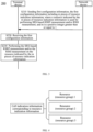
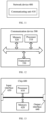
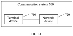
- the communication system 100 may include a network device 110, and the network device 110 may be a device in communication with a terminal device 120 (or called a communication terminal, terminal).
- the network device 110 can provide communication coverage for a specific geographic area, and can communicate with a terminal device located in the coverage area.
- FIG. 1 exemplarily shows one network device and two terminal devices.
- the communication system 100 may include a plurality of network devices and a coverage of each network device may include other numbers of terminal devices, which is not limited in the embodiments of the present application.
- the communication system 100 may also include other network entities, such as a network controller, a mobility management entity, which is not limited in the embodiments of the present application.
- network entities such as a network controller, a mobility management entity, which is not limited in the embodiments of the present application.
- the device with a communication function in the network/system in the embodiments of the present application may be referred to as a communication device.
- the communication device may include the network device 110 and the terminal device 120 with the communication function, and the network device 110 and the terminal device 120 may be a specific device described above, which will not be repeated here.
- the communication device may also include other devices in the communication system 100, for example, other network entities such as a network controller, a mobility management entity, etc., which are not limited in the embodiments of the present application.
- system and “network” are often used interchangeably herein.
- the term “and/or” herein is only an association relationship for describing associated objects, and means that there can be three types of relationships.
- the expression “A and/or B” may indicate three cases: A exists alone, A and B exist at the same time, and B exists alone.
- the character “j” herein generally indicates that the associated objects before and after the character are in an "or” relationship.
- the terminal device can refer to a user equipment (User Equipment, UE), an access terminal, a user unit, a user station, a mobile station, a mobile platform, a remote station, a remote terminal, a mobile device, a user terminal, a terminal, a wireless communication device, a user agent or a user apparatus.
- UE User Equipment
- the terminal device can be a station (STATION, ST), a cellular phone, a cordless phone, a session initiation protocol (Session Initiation Protocol, SIP) phone, a wireless local loop (Wireless Local Loop, WLL) station, a personal digital assistant (Personal Digital Assistant, PDA) device, a handheld device with a wireless communication function, a computing device with a wireless communication function, or other processing devices connected to a wireless modem and having a wireless communication function, an in-vehicle device, a wearable device or a terminal device in a next generation communication system, such as a NR network or a terminal in a future evolutional public land mobile network (Public Land Mobile Network, PLMN), etc.
- SIP Session Initiation Protocol
- WLL Wireless Local Loop
- PDA Personal Digital Assistant
- the terminal device may also be a wearable device.
- the wearable device can also be called a wearable smart device, which is a general term for using a wearable technology to intelligently design an everyday wear and develop a wearable device, such as glasses, gloves, a watch, clothing and a shoe.
- the wearable device is a portable device that is worn directly on a body or integrated into a cloth or accessories of a user.
- the wearable device is not only a hardware device, but also realizes a powerful function through software support, data interaction and cloud interaction.
- wearable smart devices include, for example, smart watches or smart glasses or the like which have full functions, with large sizes, and can realize complete or partial functions without relying on smart phones, as well as devices which simply focus on a certain application function and need to be used in conjunction with other devices such as smart phones, such as various smart bracelets for monitoring physical signs and smart jewelries for monitoring physical signs.
- the network device may be a device used to communicate with a mobile device.
- the network device may be an access point (Access Point, AP) in a WLAN, a base station (Base Transceiver Station, BTS) in GSM or CDMA, or a base station (NodeB, NB) in WCDMA, or an evolved base station (Evolutional Node B, eNB or eNodeB) in LTE, or a relay station or an access point, or in-vehicle device, a wearable device and a network device (gNB) in a NR network or a network device in a future evolutional PLMN network, etc.
- Access Point Access Point
- BTS Base Transceiver Station
- NodeB, NB base station
- Evolutional Node B, eNB or eNodeB evolved base station
- gNB network device
- gNB network device
- the network device provides service for a cell
- the terminal device communicates with the network device thought a transmission resource (e.g., a frequency domain resource or a spectrum resource) used by the cell.
- the cell may be a cell corresponding to the network device (e.g., a base station), and the cell may belong to a macro base station or a base station corresponding to a small cell.
- the small cell here can include: a metro cell, a microcell, a pico cell, a femto cell, etc. These small cells have the characteristics of small coverage and low transmission power, and are suitable for providing a high-speed data transmission service.
- Different services or applications (Application, APP) of the terminal device may have different requirements in terms of uplink data rate and downlink data rate.
- the downlink data rate is generally higher than the uplink data rate.
- the uplink data rate of some services/apps may be higher than the downlink data rate thereof.
- the uplink data rate is higher than the downlink data rate.
- different operations may have different requirements for the uplink data rate and the downlink data rate. For example, when uploading videos for sharing, the uplink data rate may be higher than the downlink data rate, while watching videos shared by friends, the uplink data rate may be lower than the uplink data rate.
- a wireless network keeps fixed or semi-static (semi-static) uplink resource allocation and downlink resource allocation (for example, fixed uplink time slot configuration and downlink time slot configuration in LTE/NR system), service transmission may not be optimally matched in a short time, thus resulting in inefficient utilization of a resource and a problem that experience of the terminal device cannot be further improved.
- a method of dynamically adjusting an uplink transmission direction and a downlink transmission direction (a transmission resource) can be adopted. For example, if the amount of downlink data of the current cell or the terminal device increases, the network device can use more resources for downlink transmission (for example, more time slots are used for the downlink transmission).
- NR system proposes a flexible time slot format, in which the time slot format includes several downlink symbols, several flexible symbols and several uplink symbols in a time slot.
- a NR system proposes a flexible time slot format, where the time slot format includes information about several downlink symbols, several flexible symbols, and several uplink symbols in a time slot.
- Table 1 The configuration of some time slot formats supported in the current NR protocol can be shown in Table 1.
- Table 1 one row represents a time slot. It can be seen that there are 14 symbols in each time slot. "D” represents a downlink (Downlink) symbol in Table 1, "U” represents an uplink (Uplink) symbol, and "F” represents a flexible symbol. It can be seen that a slot format 0 indicates that all 14 symbols in a slot are downlink symbols, a slot format 1 indicates that all 14 symbols in a slot are uplink symbols, and a slot format 20 indicates that the first 2 symbols are configured as downlink symbols, the last symbol is configured as an uplink symbol, and the middle 11 symbols are configured as flexible symbols.
- a cell changes the time slot format in a relatively dynamical manner, or the network device changes its corresponding time slot format for one or some terminal devices, additional interference (relative to static uplink configuration and downlink configuration) would be caused.
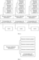
- FIG. 2 Take FIG. 2 as an example for illustration. If neighboring cells all use the same uplink and downlink configuration, when UE 1-2 receives a downlink signal, other cells are also performing downlink signal transmission (if any), there will be no uplink signal transmission, so UE 1-2 may only receive interference from other base stations (for example, a type 1 interference in the figure).
- a current service of UE 3-2 is mainly a large amount of upload data traffic
- a base station 3 may configure more uplink resources (for example, more time slots are configured as full uplink, or more symbols in some time slots are configured as uplink) for the transmission of UE 3-2
- additional interference may be formed, for example, a type 2 interference shown in the figure, that is, when receiving downlink data transmission, UE 1-2 may be interfered by an uplink signal sent by the neighboring UE 3-2.
- the type 2 interference may also be occur.
- all symbols in a time slot are flexible symbols (such as a time slot format 2 in Table 1)
- gNB1 may use the time slot for downlink transmission of UE 1-2
- gNB3 may use the time slot for uplink transmission of UE 3-2
- the above-mentioned type 2 interference will also occur.
- CLI cross-link interference
- CLI can be interference caused by uplink transmission of at least one terminal device to receiving of a neighboring terminal device. It should be understood that the CLI measurement is not limited to between terminals, but can also be used in other similar situations, such as between network devices.
- a measured value or a reported value measured by the CLI measurement can be in two ways: channel sounding reference signal-reference signal received power (Sounding Reference Signal-Reference Signal Received Power, SRS-RSRP) and received signal strength indicator (Received Signal Strength Indicator, RSSI).
- SRS-RSRP Sounding Reference Signal-Reference Signal Received Power
- RSSI Received Signal Strength Indicator
- the SRS-RSRP is SRS-based RSRP, i.e., an RSRP value is obtained by measuring an SRS.
- the network device can configure an SRS for SRS-RSRP measurement of the terminal device.
- Information configured by the network device can include, but is not limited to, the following information: a time-frequency resource, a SRS sequence, a cyclic shift, and a measurement period for measuring the SRS by the terminal device.
- the network device can configure a set of time-frequency resources for the RSSI measurement at the terminal device, where the configuration can include a symbol level indication and a physical resource block (Physical Resource Block, PRB) level indication.
- PRB Physical Resource Block
- a measurement quantity is the RSSI
- the measurement of the terminal device is simple, however, different interference sources cannot be distinguished; or, in order to recognize the interference source, a signaling overhead is too high.
- the method of the embodiments of the present application can also be applied to other scenarios, such as interference from other network devices to the terminal device, interference between neighboring cells, or the type 1 interference mentioned above, and so on.
- FIG. 3 is a schematic flowchart of a wireless communication method 200 according to an embodiment of the present application, as shown in FIG. 3 , the method 200 can include the following:
- each of the m pieces of resource indication information is used for indicating at least one or at least one set of SRS resource information and/or time-frequency resource information, where a resource indicated by the SRS resource information is used for performing the SRS-based RSRP measurement, a resource indicated by the time-frequency resource information is used for performing the RSSI measurement.
- the SRS resource information and the time-frequency resource information can be configured in one measurement object information element (Information Element, IE). That is, different resource configurations can be completed in one measurement object IE, thus reducing configuration signaling overheads.
- Information Element Information Element
- the SRS resource information and the time-frequency resource information can be configured by multiplexing an existing measurement object IE, e.g., multiplex an existing measurement object IE (with a structure of MeasObjectNR), it should be noted that the multiplexing of the existing measurement object IE to configure the SRS resource information and the time-frequency resource information can reduce standardization work.
- an existing measurement object IE e.g., multiplex an existing measurement object IE (with a structure of MeasObjectNR)
- MeasObjectNR MeasObjectNR
- one measurement object configuration can complete measurement for different purposes, thus reducing configuration signaling overheads.
- one measurement object IE includes a configuration field for mobility measurement configuration, and the configuration field further includes configuration information corresponding to the SRS resource information and/or the time-frequency resource information.
- Example 1 the following structure of MeasObjectNR includes a reference signal configuration field (ReferenceSignalConfig) for mobility measurement configuration. And the ReferenceSignalConfig field also includes the configuration information corresponding to the SRS resource information and/or the time-frequency resource information.
- the structure of MeasObjectNR can also include some other fields, and only the field information related to the present application is displayed as follows.
- the SRS resource information is optional (OPTIONAL) configuration information
- the SRS resource information may not be included in the configuration of the ReferenceSignalConfig structure.
- the time-frequency resource information is optional configuration information
- the time-frequency resource information may not be included in the configuration of the ReferenceSignalConfig structure.
- one measurement object IE includes a first configuration field for mobility measurement configuration, and the measurement object IE further includes a second configuration field, the second configuration field includes configuration information corresponding to the SRS resource information and/or the time-frequency resource information.
- a sequence (SEQUENCE) structure or a choice (CHOICE) structure in the second configuration field carries the configuration information corresponding to the SRS resource information and/or the time-frequency resource information.
- Example 2 the following structure of MeasObjectNR includes a reference ReferenceSignalConfig for mobility measurement configuration, and the structure of MeasObjectNR also includes a ReferenceSignalConfig2 field, the ReferenceSignalConfig2 field includes the configuration information corresponding to the SRS resource information and/or the time-frequency resource information.
- the structure of MeasObjectNR also includes some other fields, and only the field information related to the present application is displayed as follows.
- the SRS resource information is optional configuration information
- the SRS resource information may not be included in the configuration of the above-mentioned ReferenceSignalConfig structure.
- the time-frequency resource information is optional configuration information
- the time-frequency resource information may not be included in the configuration of the above-mentioned ReferenceSignalConfig structure.
- the SRS resource information and the time-frequency resource information can be configured by using a newly defined measurement object IE.
- one measurement object IE only includes configuration information corresponding to the SRS resource information and/or the time-frequency resource information. That is, this measurement object IE is a newly defined measurement object IE for the SRS resource information and/or the time-frequency resource information. In an implementation, a sequence structure or a choice structure in the measurement object IE carries the configuration information corresponding to the SRS resource information and/or the time-frequency resource information. It should be noted that configuring the SRS resource information and/or the time-frequency resource information based on the newly field measurement object IE can save some unnecessary reporting quantities and thus reduce resources required for reporting, and at the same time, the signaling becomes simpler.
- Example 3 the following structure of MeasObjectNRCLI (a newly defined measurement object IE) includes the configuration information corresponding to the SRS resource information and/or the time-frequency resource information.
- the SRS resource information is optional configuration information
- the SRS resource information may not be included in the configuration of the above-mentioned ReferenceSignalConfig2 structure or the configuration of SEQUENCE structure.
- the time-frequency resource information is optional configuration information
- the time-frequency resource information may not be included in the configuration of the ReferenceSignalConfig2 structure or the configuration of SEQUENCE structure.
- the SRS resource information and the time-frequency resource information cannot be configured in one measurement object IE. That is, the SRS resource information and the time-frequency resource information need to be configured in different measurement object IEs, the way in which the configuration is done in different measurement object IEs can reduce processing complexity of the terminal device.
- the configuration information corresponding to the SRS resource information and/or the time-frequency resource information is optional configuration information.
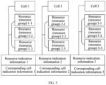
- the first configuration information further includes cell indication information
- the cell indication information is used for indicating a cell corresponding to the resource indicated by the m pieces of resource indication information, that is, the configuration information includes the m pieces of resource indication information and the cell indication information.
- the terminal device when the first configuration information includes the m pieces of resource indication information and the cell indication information, when the terminal device operates with multi-carrier (Carrier Aggregation (Carrier Aggregation, CA)) or multiple connectivity (multiple connectivity, where double link is a special form), it can be flexibly indicated that the measurement is performed on a corresponding resource of which serving cell (serving cell), thus providing better flexibility for network cooperation.
- multi-carrier Carrier Aggregation (Carrier Aggregation, CA)
- multiple connectivity multiple connectivity, where double link is a special form
- the first configuration information specifically only includes one piece of cell indication information, and a cell indicated by the one piece of cell indication information corresponds to the resource indicated by the m pieces of resource indication information.
- the first configuration information specifically includes m pieces of cell indication information, and a cell indicated by i-th cell indication information corresponds to a resource indicated by i-th resource indication information, 0 ⁇ i ⁇ m.
- the m pieces of resource indication information and the m pieces of cell indication information correspond to a first IE
- the a first field in the first IE includes the m pieces of resource indication information and the m pieces of cell indication information
- the resource indication information indicates three resource (or a resource group), they are marked as a resource (a resource group) 1 to a resource (a resource group) 3, the first field (e.g., ReferenceSignalConfig field) in the first IE indicates the resource (the resource group) 1 to the resource (the resource group) 3.
- the first field e.g., ReferenceSignalConfig field
- the m pieces of resource indication information and the m pieces of cell indication information correspond to the first IE
- the first field in the first IE includes a first sequence structure for the m pieces of resource indication information and a second sequence structure for the m pieces of cell indication information, where the first sequence structure includes m first elements, and an i-th first element corresponds to i-th resource indication information, the second sequence structure includes m second elements, and an i-th second element corresponds to i-th cell indication information.
- one field in the first IE may include the first sequence structure and the second sequence structure.
- the m pieces of resource indication information and the m pieces of cell indication information correspond to a first IE
- resource indication information 1 is used for indicating three resources (or resource groups), they are marked as a resource (a resource group) 1-1 to a resource (a resource group) 1-3
- resource indication information 2 is used for indicating three resources (or resource groups), they are marked as a resource (a resource group) 2-1 to a resource (a resource group) 2-3
- resource indication information 3 is used for indicating three resources (or resource groups), they are marked as a resource (a resource group) 3-1 to a resource (a resource group) 3-3
- the resource indication information 1 corresponds to the cell indication information 1
- the resource indication information 2 corresponds to the cell indication information 2
- the resource indication information 3 corresponds to the cell indication information 3
- the first field in the first IE can indicate a resource (or a resource group), meanwhile, the first field may also indicate a cell.
- the m pieces of resource indication information and the m pieces of cell indication information correspond to the first IE
- the first field in the first IE includes a first sequence structure for the m pieces of resource indication information
- a second field in the first IE includes a second sequence structure for the m pieces of cell indication information
- the first sequence structure includes m first elements
- an i-th first element corresponds to i-th resource indication information
- the second sequence structure includes m second elements
- an i-th second element corresponds to i-th cell indication information.
- the m pieces of resource indication information and the m pieces of cell indication information correspond to a first IE
- resource indication information 1 is used for indicating three resources (or resource groups), they are marked as a resource (a resource group) 1-1 to a resource (a resource group) 1-3
- resource indication information 2 is used for indicating three resources (or resource groups), they are marked as a resource (a resource group) 2-1 to a resource (a resource group) 2-3
- resource indication information 3 is used for indicating three resources (or resource groups), they are marked as a resource (a resource group) 3-1 to a resource (a resource group) 3-3
- the resource indication information 1 corresponds to the cell indication information 1
- the resource indication information 2 corresponds to the cell indication information 2
- the resource indication information 3 corresponds to the cell indication information 3
- the first field in the first IE can indicate a resource (or a resource group), meanwhile, the second field in the first IE may also indicate a cell.
- the m pieces of resource indication information and the m pieces of cell indication information correspond to the first IE
- the first field in the first IE includes a first sequence structure for the m pieces of resource indication information and the m pieces of cell indication information, where the first sequence structure includes m elements, and an i-th element corresponds to i-th resource indication information and i-th cell indication information.
- the m pieces of resource indication information and the m pieces of cell indication information correspond to a first IE
- the resource indication information X indicates three resources (or resource groups), they are marked as a resource (a resource group) 1 to a resource (a resource group) 3
- the first field in the first IE indicates the resource (the resource group) 1 to the resource (the resource group) 3 and cell indication information X corresponding to the resource indication information X.
- the first configuration information includes a field corresponding to cell indication information, and the cell indication information is not configured, a default cell corresponds to the resource indicated by the m pieces of resource indication information.
- a default cell corresponds to the resource indicated by the m pieces of resource indication information.
- the default cell includes but not limited to at least one of the following:
- the m pieces of resource indication information correspond to a first IE
- a first field in the first IE includes a first sequence structure, where the first sequence structure includes m elements, and an i-th element corresponds to i-th resource indication information.
- the m pieces of resource indication information correspond to a first IE
- the resource indication information indicates three resources (or resource groups), they are marked as a resource (a resource group) 1 to a resource (a resource group) 3
- the first field in the first IE indicates the resource (the resource group) 1 to the resource (the resource group) 3.
- the m pieces of resource indication information correspond to a first IE
- m fields in the first IE correspond to the m pieces of resource indication information, where an i-th field corresponds to i-th resource indication information.
- the m pieces of resource indication information correspond to a first IE
- the resource indication information indicates three resources (or resource groups), they are marked as a resource (a resource group) 1 to a resource (a resource group) 3
- the first field in the first IE indicates the resource (the resource group) 1
- a second field in the first IE indicates the resource (the resource group) 2
- a third field in the first IE indicates the resource (the resource group) 3.
- one measurement object IE includes a configuration field for mobility measurement configuration, and the configuration field further includes configuration information corresponding to the cell indication information and/or the m pieces of resource indication information.
- the configuration information corresponding to the cell indication information and/or the m pieces of resource indication information can multiplex an existing measurement object IE, and only the configuration field for mobility measurement configuration needs to be modified.
- the related description of Example 1 above it is only necessary to replace the SRS resource information and/or the time-frequency resource information in Example 1 with the m pieces of resource indication information and/or the cell indication information, details are not repeated here.
- one measurement object IE includes a first configuration field for mobility measurement configuration, and the measurement object IE further includes a second configuration field, the second configuration field includes configuration information corresponding to the cell indication information and/or the m pieces of resource indication information.
- a sequence structure or a choice structure in the second configuration field carries the configuration information corresponding to the cell indication information and/or the m pieces of resource indication information.
- the configuration information corresponding to the cell indication information and/or the m pieces of resource indication information can multiplex an existing measurement object IE, and a field including the configuration information corresponding to the m pieces of resource indication information and/or the cell indication information needs to be added.
- a field including the configuration information corresponding to the m pieces of resource indication information and/or the cell indication information needs to be added.
- one measurement object IE includes the configuration information corresponding to the cell indication information and/or the m pieces of resource indication information, and does not include configuration information for mobility measurement.
- a sequence structure or a choice structure in the measurement object IE carries the configuration information corresponding to the cell indication information and/or the m pieces of resource indication information.
- the configuration information corresponding to the cell indication information and/or the m pieces of resource indication information cannot multiplex an existing measurement object IE, and in particular, cannot multiplex the measurement object IE including the configuration information for mobility measurement.
- the related description of Example 3 above it is only necessary to replace the SRS resource information and/or the time-frequency resource information in Example 3 with the m pieces of resource indication information and/or the cell indication information, details are not repeated here.
- the configuration information corresponding to the m pieces of resource indication information and/or the cell indication information is (are) optional configuration information.
- the first configuration information further includes BWP indication information, the BWP indication information is used for indicating a BWP corresponding to the resource indicated by the m pieces of resource indication information.
- the terminal device when configuring a plurality of BWPs in a serving cell, the terminal device can flexibly indicate that measurement is performed on a corresponding resource of which BWP or which BWPs, so as to provide better flexibility for network cooperation.
- the first configuration information may include the m pieces of resource indication information and the BWP indication information, and may also include the m pieces of resource indication information, the cell indication information and the BWP indication information.
- the first configuration information specifically includes m pieces of BWP indication information, a BWP indicated by i-th BWP indication information corresponds to a downlink BWP indicated by i-th resource indication information, 0 ⁇ i ⁇ m.
- the m pieces of resource indication information and the m pieces of BWP indication information correspond to a second IE, and a first field in the second IE includes the m pieces of resource indication information and the m pieces of BWP indication information.
- the m pieces of resource indication information and the m pieces of BWP indication information correspond to a second IE
- a first field in the second IE includes a first sequence structure for the m pieces of resource indication information and a second sequence structure for the m pieces of BWP indication information, where the first sequence structure includes m first elements, and an i-th first element corresponds to i-th resource indication information, the second sequence structure includes m second elements, and an i-th second element corresponds to i-th BWP indication information.
- the m pieces of resource indication information and the m pieces of BWP indication information correspond to a second IE
- a first field in the second IE includes a first sequence structure for the m pieces of resource indication information
- a second field in the second IE includes a second sequence structure for the m pieces of BWP indication information
- the first sequence structure includes m first elements
- an i-th first element corresponds to i-th resource indication information
- the second sequence structure includes m second elements
- i-th second element corresponds to i-th BWP indication information.
- the m pieces of resource indication information and the m pieces of BWP indication information correspond to a second IE
- a first field in the second IE includes a first sequence structure for the m pieces of resource indication information and the m pieces of BWP indication information, where the first sequence structure includes m elements, and an i-th first element corresponds to i-th resource indication information and i-th BWP indication information.
- a default downlink BWP corresponds to the resource indicated by the m pieces of resource indication information.
- a default downlink BWP corresponds to the resource indicated by the m pieces of resource indication information.
- the default downlink BWP includes but not limited to at least one of:
- the m pieces of resource indication information correspond to a second IE
- a first field in the second IE includes a first sequence structure, where the first sequence structure includes m elements, and an i-th element corresponds to i-th resource indication information.
- the m pieces of resource indication information correspond to a second IE
- m fields in the second IE correspond to the m pieces of resource indication information, where an i-th field is used for indicating i-th resource indication information.
- one measurement object IE includes a configuration field for mobility measurement configuration, and the configuration field further includes configuration information corresponding to the BWP indication information and/or the m pieces of resource indication information.
- the configuration information of the BWP indication information and/or the m pieces of resource indication information can multiplex an existing measurement object IE, and only the configuration field for mobility measurement configuration in this measurement object IE needs to be modified, specifically, reference may be made to the related description of Example 1 above, it is only necessary to replace the SRS resource information and/or the time-frequency resource information in Example 1 with the m pieces of resource indication information and/or the BWP indication information, details are not repeated here.
- one measurement object IE includes a first configuration field for mobility measurement configuration, and the measurement object IE further includes a third configuration field, the third configuration field includes configuration information corresponding to the BWP indication information and/or the m pieces of resource indication information.
- a sequence structure or a choice structure in the third configuration field carries the configuration information corresponding to the BWP indication information and/or the m pieces of resource indication information.
- the configuration information corresponding to the BWP indication information and/or the m pieces of resource indication information can multiplex an existing measurement object IE, and a field including the configuration information corresponding to the BWP indication information and/or the m pieces of resource indication information needs to be added.
- a field including the configuration information corresponding to the BWP indication information and/or the m pieces of resource indication information needs to be added.
- one measurement object IE includes configuration information corresponding to the BWP indication information and/or the m pieces of resource indication information , and does not include configuration information for mobility measurement.
- a sequence structure or a choice structure in the measurement object IE carries the configuration information corresponding to the BWP indication information and/or the m pieces of resource indication information.
- the configuration information corresponding to the BWP indication information and/or the m pieces of resource indication information cannot multiplex an existing measurement object IE, and in particular, cannot multiplex the measurement object IE including the configuration information for mobility measurement.
- the related description of Example 3 above it is only necessary to replace the SRS resource information and/or the time-frequency resource information in Example 3 with the m pieces of resource indication information and/or the BWP indication information, details are not repeated here.
- the configuration information corresponding to the BWP indication information and/or the m pieces of resource indication information is optional configuration information.
- the SRS resource information includes an SRS sequence identification.
- the SRS resource information includes the SRS sequence identification, so as to ensure an SRS generation sequence.
- the network device can configure a cell identification corresponding to an SRS generation sequence to ensure the SRS generation sequence.
- the terminal device may receive second configuration information sent by the network device, where the second configuration information is used for indicating the cell identification corresponding to the SRS generation sequence.
- the first configuration information includes a field corresponding to the SRS sequence identification, and the SRS sequence identification is not configured, which can be understood as: the SRS sequence identification is optional configuration information.
- the network device can configure a cell identification corresponding to an SRS generation sequence to ensure the SRS generation sequence.
- the terminal device may receive second configuration information sent by the network device, where the second configuration information is used for indicating the cell identification corresponding to the SRS generation sequence.
- the first configuration information does not include the field corresponding to the SRS sequence identification, which can be understood as: the protocol does not support configuring the SRS sequence identification.
- the terminal device receives second configuration information, the second configuration information being used for indicating a cell identification corresponding to an SRS generation sequence, where,
- the SRS sequence identification corresponds to an initial parameter of an SRS generation sequence, that is, the generation of the SRS sequence is performed based on the SRS sequence identification. If the network device has configured a cell identification corresponding to the SRS generation sequence, and the SRS resource information does not include the SRS sequence identification, then the cell identification corresponds to an initial parameter of an SRS generation sequence, that is, the generation of the SRS sequence generation is performed based on the cell identification.
- the first configuration information and the second configuration information are carried in one radio resource control (Radio Resource Control, RRC) signaling.
- RRC Radio Resource Control
- the L3 filtering can be performed with the following formula 1.
- F n 1 ⁇ a * F n ⁇ 1 + a * M n
- M n is the latest measurement result received from a physical layer
- F n is the measurement result after filtering, which is used for reporting or evaluation of a reporting criteria
- F n-1 is the old (last time) filtered measurement result, where F 0 is set to M 1 when a measurement result is obtained from the physical layer for the first time
- a 1/2 ( ki /4) , where k i is the filter coefficient corresponding to the measurement quantity.
- the terminal device filters a measurement result according to an L3 filter parameter, where the L3 filter parameter is preconfigured or configured by a network device.
- the L3 filter parameter is 4.
- the L3 filter parameter is preconfigured, that is, a fixed L3 filter parameter is adopted, such as 4, in this way, the signaling overhead and the complexity of the terminal device can be reduced.
- the network device configures the L3 filter parameter to keep flexibility and set optimized parameters for different measurements to improve performance.
- the network device sends third configuration information to the terminal device, the third configuration information being used for configuring the L3 filter parameter.
- the network device can respectively configure one set of L3 filter parameters.
- the network device can respectively configure one set of or two sets of L3 filter parameters.
- each set of L3 filter parameters correspond to two parameters (respectively corresponding to the SRS-RSRP and the RSSI).
- each set of L3 filter parameters correspond to one parameter (corresponding to the SRS-RSRP).
- each set of L3 filter parameters correspond to one or two parameters (i.e., configuration of the two parameters is optional).
- the network device can configure multiple sets of L3 filter parameters, so that the terminal device can flexibly choose in the multiple sets of L3 filter parameters, thus keeping flexibility and improving performance.
- the L3 filter parameter is only for the SRS-based RSRP measurement. That is, the L3 filtering is only performed on an SRS-based RSRP measurement quantity.
- the L3 filter parameter is for the SRS-based RSRP measurement and the RSSI measurement. That is, the L3 filtering is performed on an SRS-based RSRP measurement quantity and an RSSI measurement quantity.
- the L3 filter parameter is for the SRS-based RSRP measurement, and whether to filter an RSSI measurement quantity based on the L3 filter parameter is determined by the terminal device or according to a configuration of the network device.
- an IE for a filter parameter includes a filter configuration field for a synchronization signal block (Synchronization Signal Block, SSB) and/or a channel state information reference signal (Channel State Information Reference Signal, CSI-RS), the filter configuration field further includes configuration information for the L3 filter parameter.
- SSB Synchronization Signal Block
- CSI-RS Channel State Information Reference Signal
- the L3 filter parameter can multiplex an existing IE for the filter parameter, only the filter configuration field for an SSB and/or a CSI-RS in the IE for the filter parameter needs to modify.
- an IE for the filter parameter is a quantity configuration (QuantityConfig) IE
- the QuantityConfig IE includes a filter configuration field (FilterConfig) for an SSB and/or a CSI-RS
- the FilterConfig may be:
- the second filter configuration field includes the configuration information for the L3 filter parameter.
- the L3 filter parameter can multiplex an existing IE for the filter parameter. Only the configuration information field for the L3 filter parameter is added in the IE for the filter parameter.
- the IE for the filter parameter is a quantity configuration (QuantityConfig)
- the QuantityConfig IE includes a filter configuration field (FilterConfig) for an SSB and/or a CSI-RS
- a filter parameter (filterCoefficientRSRP2) is added in the QuantityConfig IE, where the filterCoefficientRSRP2 can only indicate a filter parameter of an SRS-based RSRP measurement quantity, or can indicate a filter parameter of an SRS-based RSRP measurement quantity and a filter parameter for an RSSI measurement quantity; the filter parameter of the SRS-based RSRP measurement quantity has a default value of fc4, and the filter parameter for the RSSI measurement quantity is optional configuration information, or, the filter parameter for the RSSI measurement quantity has a default value of fc4.
- one IE for a filter parameter includes configuration information for the L3 filter parameter, and does not include filter configuration information for an SSB and/or a CSI-RS.
- FilterConfig2 (a newly defined IE for the filter parameter) includes the configuration information of an L3 filter parameter, and the filter parameter for the SRS-based RSRP measurement quantity is fc4 by default. Or the following structure of FilterConfig2 cannot include the filter parameter for the RSSI measurement quantity.
- FilterConfig2 (a newly defined IE for filter parameter) includes the configuration information of an L3 filter parameter, and the filter parameter of the SRS-based RSRP measurement quantity is optional configuration information, and the filter parameter for the RSSI measurement quantity is optional configuration information.
- the following structure of FilterConfig2 cannot include the filter parameter for the RSSI measurement quantity.
- the terminal device can report the measurement result based on the first configuration information to the network device.
- the network device can decide the uplink transmission and downlink transmission method according to the received report information, and perform corresponding transmission with the related terminal device. For example,
- the network device can configure the SRS resource information and/or the time-frequency resource information, so that the SRS-based RSRP measurement is performed based on a resource indicated by the SRS resource information and the RSSI measurement is performed based on a resource indicated by the time-frequency resource information, and the network device also configures the cell indication information and/or the BWP indication information, so as to flexibly indicate that measurement is performed on a corresponding resource of which serving cell, or flexibly indicate that measurement is performed on which downlink BWP, so as to provide better flexibility for network cooperation.
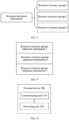
- FIG. 10 is a schematic block diagram of a terminal device according to an embodiment of the present application. As show in FIG. 10 , the terminal device includes:
- each of the m pieces of resource indication information is used for indicating at least one or at least one set of SRS resource information and/or time-frequency resource information, and a resource indicated by the SRS resource information is used for performing the SRS-based RSRP measurement, a resource indicated by the time-frequency resource information is used for performing the RSSI measurement.
- the SRS resource information and the time-frequency resource information can be configured in one measurement object information element IE.
- the SRS resource information and the time-frequency resource information cannot be configured in one measurement object IE.
- one measurement object IE includes a configuration field for mobility measurement configuration, and the configuration field further includes configuration information corresponding to the SRS resource information and/or the time-frequency resource information.
- one measurement object IE includes a first configuration field for mobility measurement configuration, and the measurement object IE further includes a second configuration field, the second configuration field includes configuration information corresponding to the SRS resource information and/or the time-frequency resource information.
- a sequence structure or a choice structure in the second configuration field carries the configuration information corresponding to the SRS resource information and/or the time-frequency resource information.
- one measurement object IE only includes configuration information corresponding to the SRS resource information and/or the time-frequency resource information.
- a sequence structure or a choice structure in the measurement object IE carries the configuration information corresponding to the SRS resource information and/or the time-frequency resource information.
- the configuration information corresponding to the SRS resource information and/or the time-frequency resource information is optional configuration information.
- the first configuration information further includes cell indication information, the cell indication information is used for indicating a cell corresponding to the resource indicated by the m pieces of resource indication information.
- the first configuration information specifically only includes one piece of cell indication information, and a cell indicated by the one piece of cell indication information corresponds to the resource indicated by the m pieces of resource indication information.
- the first configuration information specifically includes m pieces of cell indication information, and a cell indicated by i-th cell indication information corresponds to a resource indicated by i-th resource indication information, 0 ⁇ i ⁇ m.
- the m pieces of resource indication information and the m pieces of cell indication information correspond to a first IE
- a first field in the first IE includes the m pieces of cell indication information and the m pieces of cell indication information.
- the m pieces of resource indication information and the m pieces of cell indication information correspond to a first IE
- a first field in the first IE includes a first sequence structure for the m pieces of resource indication information and a second sequence structure for the m pieces of cell indication information, where the first sequence structure includes m first elements, and an i-th first element corresponds to i-th resource indication information, the second sequence structure includes m second elements, and an i-th second element corresponds to i-th cell indication information.
- the m pieces of resource indication information and the m pieces of cell indication information correspond to a first IE
- a first field in the first IE includes a first sequence structure for the m pieces of resource indication information
- a second field in the first IE includes a second sequence structure for the m pieces of cell indication information
- the first sequence structure includes m first elements
- an i-th first element corresponds to i-th resource indication information
- the second sequence structure includes m second elements
- an i-th second element corresponds to i-th cell indication information
- the m pieces of resource indication information and the m pieces of cell indication information correspond to a first IE
- a first field in the first IE includes a first sequence structure for the m pieces of resource indication information and the m pieces of cell indication information, where the first sequence structure includes m elements, and an i-th element corresponds to i-th resource indication information and i-th cell indication information.
- a default cell corresponds to the resource indicated by the m pieces of resource indication information.
- a default cell corresponds to the resource indicated by the m pieces of resource indication information.
- the default cell is at least one of:
- the m pieces of resource indication information correspond to a first IE
- a first field in the first IE includes a first sequence structure, where the first sequence structure includes m elements, and an i-th element corresponds to i-th resource indication information.
- the m pieces of resource indication information correspond to a first IE
- m fields in the first IE correspond to the m pieces of resource indication information
- an i-th field corresponds to i-th resource indication information
- one measurement object IE includes a configuration field for mobility measurement configuration, and the configuration field further includes configuration information corresponding to the cell indication information and/or the m pieces of resource indication information.
- one measurement object IE includes a first configuration field for mobility measurement configuration, and the measurement object IE further includes a second configuration field, the second configuration field includes configuration information corresponding to the cell indication information and/or the m pieces of resource indication information.
- a sequence structure or a choice structure in the second configuration field carries the configuration information corresponding to the cell indication information and/or the m pieces of resource indication information.
- one measurement object IE comprises configuration information corresponding to the cell indication information and/or the m pieces of resource indication information, and does not comprises configuration information for mobility measurement.
- a sequence structure or a choice structure in the second configuration field carries the configuration information corresponding to the cell indication information and/or the m pieces of resource indication information.
- the configuration information corresponding to the cell indication information and/or the m pieces of resource indication information is optional configuration information.
- the first configuration information further includes BWP indication information, the BWP indication information is used for indicating a BWP corresponding to the resource indicated by the m pieces of resource indication information.
- the first configuration information specifically includes m pieces of BWP indication information, and a BWP indicated by i-th BWP indication information corresponds to a downlink BWP indicated by i-th resource indication information, 0 ⁇ i ⁇ m.
- the m pieces of resource indication information and the m pieces of BWP indication information correspond to a second IE, and a first field in the second IE includes the m pieces of resource indication information and the m pieces of BWP indication information.
- the m pieces of resource indication information and the m pieces of BWP indication information correspond to a second IE
- a first field in the second IE includes a first sequence structure for the m pieces of resource indication information and a second sequence structure for the m pieces of BWP indication information, where the first sequence structure includes m first elements, and an i-th first element corresponds to i-th resource indication information, the second sequence structure includes m second elements, and an i-th second element corresponds to i-th BWP indication information.
- the m pieces of resource indication information and the m pieces of BWP indication information correspond to a second IE
- a first field in the second IE includes a first sequence structure for the m pieces of resource indication information
- a second field in the second IE includes a second sequence structure for the m pieces of BWP indication information
- the first sequence structure includes m first elements
- an i-th first element corresponds to i-th resource indication information
- the second sequence structure includes m second elements
- an i-th second element corresponds to i-th BWP indication information.
- the m pieces of resource indication information and the m pieces of BWP indication information correspond to a second IE
- a first field in the second IE includes a first sequence structure for the m pieces of resource indication information and the m pieces of BWP indication information, where the first sequence structure includes m elements, and an i-th element corresponds to i-th resource indication information and i-th BWP indication information.
- a default downlink BWP corresponds to the resource indicated by the m pieces of resource indication information.
- a default downlink BWP corresponds to the resource indicated by the m pieces of resource indication information.
- the default downlink BWP is at least one of:
- the m pieces of resource indication information correspond to a second IE
- a first field in the second IE includes a first sequence structure, where the first sequence structure includes m elements, and an i-th element corresponds to i-th resource indication information.
- the m pieces of resource indication information correspond to a second IE
- m fields in the second IE correspond to the m pieces of resource indication information, where an i-th field is used for indicating i-th resource indication information.
- one measurement object IE includes a configuration field for mobility measurement configuration, and the configuration field further includes configuration information corresponding to the BWP indication information and/or the m pieces of resource indication information.
- one measurement object IE includes a first configuration field for mobility measurement configuration, and the measurement object IE further includes a third configuration field, the third configuration field includes configuration information corresponding to the BWP indication information and/or the m pieces of resource indication information.
- a sequence structure or a choice structure in the third configuration field carries configuration information corresponding to the BWP indication information and/or the m pieces of resource indication information.
- one measurement object IE includes configuration information corresponding to the BWP indication information and/or the m pieces of resource indication information, and does not includes configuration information for mobility measurement.
- a sequence structure or a choice structure in the measurement object IE carries configuration information corresponding to the BWP indication information and/or the m pieces of resource indication information.
- the configuration information corresponding to the BWP indication information and/or the m pieces of resource indication information is optional configuration information.
- the SRS resource information includes an SRS sequence identification.
- each of the resource indication information in the m pieces of resource indication information is used for indicating at least one or a set of SRS resource information, and the first configuration information includes a field corresponding to an SRS sequence identification, and the SRS sequence identification is not configured; the communicating unit is further configured to receive second configuration information, the second configuration information being used for indicating a cell identification corresponding to an SRS generation sequence.
- the communicating unit 310 is further configured to receive second configuration information, the second configuration information being used for indicating a cell identification corresponding to an SRS generation sequence.
- the communicating unit 310 is further configured to receive second configuration information, the second configuration information being used for indicating a cell identification corresponding to an SRS generation sequence, among them,
- the first configuration information and the second configuration information are carried in one RRC signaling.
- the processing unit 320 is further configured to filter a measurement result according to an L3 filter parameter, where the L3 filter parameter is preconfigured or configured by a network device.
- the L3 filter parameter is only for the SRS-based RSRP measurement.
- the L3 filter parameter is for the SRS-based RSRP measurement and the RSSI measurement.
- the L3 filter parameter is for SRS-based RSRP measurement, and whether to filter an RSSI measurement quantity based on the L3 filter parameter is determined by the terminal device or according to a configuration of a network device.
- the filter configuration field further includes configuration information for the L3 filter parameter.
- the L3 filter parameter is configured by a network device, and an IE for the filter parameter includes a first filter configuration field for an SSB and/or a CSI-RS, and the IE for a filter parameter further includes a second filter configuration field, the second filter configuration field includes configuration information for the L3 filter parameter.
- one IE for a filter parameter includes configuration information for the L3 filter parameter, and does not include filter configuration information for an SSB and/or a CSI-RS.
- the measurement includes CLI measurement.
- a terminal device 300 can correspond to the terminal device in the method embodiment of the present application, and the above and other operations and/or functions of each unit in the terminal device 300 are respectively for implementing the corresponding flow of the terminal device in the method 200 shown in FIG. 3 , details are not repeated herein for brevity.
- FIG. 11 is a schematic block diagram of a network device 400 according to an embodiment of the present application.
- the network device 400 includes: a communicating unit 410, configured to send first configuration information, the first configuration information including m pieces of resource indication information, where a resource indicated by the m pieces of resource indication information is used for performing SRS-based RSRP measurement and/or RSSI measurement, and m is a positive integer greater than or equal to 1.
- each of the m pieces of resource indication information is used for indicating at least one or at least one set of SRS resource information and/or time-frequency resource information, and a resource indicated by the SRS resource information is used for performing the SRS-based RSRP measurement, a resource indicated by the time-frequency resource information is used for performing the RSSI measurement.
- the SRS resource information and the time-frequency resource information can be configured in one measurement object information element IE.
- the SRS resource information and the time-frequency resource information cannot be configured in one measurement object IE.
- one measurement object IE includes a configuration field for mobility measurement configuration, and the configuration field further includes configuration information corresponding to the SRS resource information and/or the time-frequency resource information.
- one measurement object IE includes a first configuration field for mobility measurement configuration, and the measurement object IE further includes a second configuration field, the second configuration field includes configuration information corresponding to the SRS resource information and/or the time-frequency resource information.
- a sequence structure or a choice structure in the second configuration field carries the configuration information corresponding to the SRS resource information and/or the time-frequency resource information.
- one measurement object IE only includes configuration information corresponding to the SRS resource information and/or the time-frequency resource information.
- a sequence structure or a choice structure in the measurement object IE carries the configuration information corresponding to the SRS resource information and/or the time-frequency resource information.
- the configuration information corresponding to the SRS resource information and/or the time-frequency resource information is optional configuration information.
- the first configuration information further includes cell indication information, the cell indication information is used for indicating a cell corresponding to the resource indicated by the m pieces of resource indication information.
- the first configuration information specifically only includes one piece of cell indication information, and a cell indicated by the one piece of cell indication information corresponds to the resource indicated by the m pieces of resource indication information.
- the first configuration information specifically includes m pieces of cell indication information, and a cell indicated by i-th cell indication information corresponds to a resource indicated by i-th resource indication information, 0 ⁇ i ⁇ m.
- the m pieces of resource indication information and the m pieces of cell indication information correspond to a first IE
- a first field in the first IE includes the m pieces of cell indication information and the m pieces of cell indication information.
- the m pieces of resource indication information and the m pieces of cell indication information correspond to a first IE
- a first field in the first IE includes a first sequence structure for the m pieces of resource indication information and a second sequence structure for the m pieces of cell indication information, where the first sequence structure includes m first elements, and an i-th first element corresponds to i-th resource indication information, the second sequence structure includes m second elements, and an i-th second element corresponds to i-th cell indication information.
- the m pieces of resource indication information and the m pieces of cell indication information correspond to a first IE
- a first field in the first IE includes a first sequence structure for the m pieces of resource indication information
- a second field in the first IE includes a second sequence structure for the m pieces of cell indication information
- the first sequence structure includes m first elements
- an i-th first element corresponds to i-th resource indication information
- the second sequence structure includes m second elements
- an i-th second element corresponds to i-th cell indication information.
- the m pieces of resource indication information and the m pieces of cell indication information correspond to a first IE
- a first field in the first IE includes a first sequence structure for the m pieces of resource indication information and the m pieces of cell indication information, where the first sequence structure includes m elements, and an i-th element corresponds to i-th resource indication information and i-th cell indication information.
- a default cell corresponds to the resource indicated by the m pieces of resource indication information.
- a default cell corresponds to the resource indicated by the m pieces of resource indication information.
- the default cell is at least one of:
- the m pieces of resource indication information correspond to a first IE
- a first field in the first IE includes a first sequence structure, where the first sequence structure includes m elements, and an i-th element corresponds to i-th resource indication information.
- the m pieces of resource indication information correspond to a first IE
- m fields in the first IE correspond to the m pieces of resource indication information
- an i-th field corresponds to i-th resource indication information
- one measurement object IE includes a configuration field for mobility measurement configuration, and the configuration field further includes configuration information corresponding to the cell indication information and/or the m pieces of resource indication information.
- one measurement object IE includes a first configuration field for mobility measurement configuration, and the measurement object IE further includes a second configuration field, the second configuration field includes configuration information corresponding to the cell indication information and/or the m pieces of resource indication information.
- a sequence structure or a choice structure in the second configuration field carries the configuration information corresponding to the cell indication information and/or the m pieces of resource indication information.
- one measurement object IE includes configuration information corresponding to the cell indication information and/or the m pieces of resource indication information, and does not includes configuration information for mobility measurement.
- a sequence structure or a choice structure in the measurement object IE carries the configuration information corresponding to the cell indication information and/or the m pieces of resource indication information.
- the configuration information corresponding to the cell indication information and/or the m pieces of resource indication information is optional configuration information.
- the first configuration information further includes bandwidth part BWP indication information, the BWP indication information is used for indicating a BWP corresponding to the resource indicated by the m pieces of resource indication information.
- the first configuration information specifically includes m pieces of BWP indication information, and a BWP indicated by i-th BWP indication information corresponds to a downlink BWP indicated by i-th resource indication information, 0 ⁇ i ⁇ m.
- the m pieces of resource indication information and the m pieces of BWP indication information correspond to a second IE, and a first field in the second IE includes the m pieces of resource indication information and the m pieces of BWP indication information.
- the m pieces of resource indication information and the m pieces of BWP indication information correspond to a second IE
- a first field in the second IE includes a first sequence structure for the m pieces of resource indication information and a second sequence structure for the m pieces of BWP indication information, where the first sequence structure includes m first elements, and an i-th first element corresponds to i-th resource indication information, the second sequence structure includes m second elements, and an i-th second element corresponds to i-th BWP indication information.
- the m pieces of resource indication information and the m pieces of BWP indication information correspond to a second IE
- a first field in the second IE includes a first sequence structure for the m pieces of resource indication information
- a second field in the second IE includes a second sequence structure for the m pieces of BWP indication information
- the first sequence structure includes m first elements
- an i-th first element corresponds to i-th resource indication information
- the second sequence structure includes m second elements
- an i-th second element corresponds to i-th BWP indication information.
- the m pieces of resource indication information and the m pieces of BWP indication information correspond to a second IE
- a first field in the second IE includes a first sequence structure for the m pieces of resource indication information and the m pieces of BWP indication information, where the first sequence structure includes m elements, and an i-th element corresponds to i-th resource indication information and i-th BWP indication information.
- a default downlink BWP corresponds to the resource indicated by the m pieces of resource indication information.
- the default downlink BWP is at least one of:
- the m pieces of resource indication information correspond to a second IE
- a first field in the second IE includes a first sequence structure, where the first sequence structure includes m elements, and an i-th element corresponds to i-th resource indication information.
- the m pieces of resource indication information correspond to a second IE
- m fields in the second IE correspond to the m pieces of resource indication information, where an i-th field is used for indicating i-th resource indication information.
- one measurement object IE includes a configuration field for mobility measurement configuration, and the configuration field further includes configuration information corresponding to the BWP indication information and/or the m pieces of resource indication information.
- one measurement object IE includes a first configuration field for mobility measurement configuration, and the measurement object IE further includes a third configuration field, the third configuration field includes configuration information corresponding to the BWP indication information and/or the m pieces of resource indication information.
- a sequence structure or a choice structure in the third configuration field carries configuration information corresponding to the BWP indication information and/or the m pieces of resource indication information.
- one measurement object IE includes configuration information corresponding to the BWP indication information and/or the m pieces of resource indication information, and does not includes configuration information for mobility measurement.
- a sequence structure or a choice structure in the measurement object IE carries configuration information corresponding to the BWP indication information and/or the m pieces of resource indication information.
- the configuration information corresponding to the BWP indication information and/or the m pieces of resource indication information is optional configuration information.
- the SRS resource information includes an SRS sequence identification.
- each of the resource indication information in the m pieces of resource indication information is used for indicating at least one or a set of SRS resource information, and the first configuration information includes a field corresponding to an SRS sequence identification, and the SRS sequence identification is not configured; the communicating unit is further configured to send second configuration information, the second configuration information being used for indicating a cell identification corresponding to an SRS generation sequence.
- the communicating unit 410 is further configured to send second configuration information, the second configuration information being used for indicating a cell identification corresponding to an SRS generation sequence.
- the communicating unit 410 is further configured to send second configuration information, the second configuration information is used for indicating a cell identification corresponding to an SRS generation sequence, where,
- the first configuration information and the second configuration information are carried in one RRC signaling.
- the communicating unit 410 is further configured to send third configuration information, the third configuration information being used for configuring an L3 filter parameter, the L3 filter parameter being used for that peer device filters a measurement result for the first configuration information.
- the L3 filter parameter is only for the SRS-based RSRP measurement.
- the L3 filter parameter is for the SRS-based RSRP measurement and the RSSI measurement.
- the L3 filter parameter is for the SRS-based RSRP measurement, and whether to filter an RSSI measurement quantity based on the L3 filter parameter is determined by the peer device or according to a configuration of a network device.
- an IE for a filter parameter includes a filter configuration field for a synchronization signal block SSB and/or a channel state information reference signal CSI-RS
- the filter configuration field further includes configuration information for the L3 filter parameter.
- an IE for a filter parameter includes a first filter configuration field for an SSB and/or a CSI-RS, and the IE for a filter parameter further includes a second filter configuration field
- the second filter configuration field includes configuration information for the L3 filter parameter.
- one IE for a filter parameter includes configuration information for the L3 filter parameter, and does not include filter configuration information for an SSB and/or a CSI-RS.
- the measurement includes CLI measurement.
- a network device 400 according to the embodiment of the present application can correspond to the network device in the method embodiment of the present application, and the above and other operations and/or functions of each unit in the network device 400 are respectively for implementing the corresponding flow of the terminal device in the method 200 shown in FIG. 3 , details are not repeated herein for brevity.
- FIG. 12 is a schematic structural diagram of a communication device 500 provided by an embodiment of the present application.
- the communication device 500 shown in FIG. 12 includes a processor 510, and the processor 510 can call and run a computer program from a memory to implement the methods in the embodiments of the present application.
- the communication device 500 can further include a memory 520.
- the processor 510 can call and run a computer program from the memory 520 to implement the methods in the embodiments of the present application.
- the memory 520 may be a separate device independent of the processor 510, or may be integrated into the processor 510.
- the communication device 500 can further include a transceiver 530, and the processor 510 can control the transceiver 530 to communicate with other devices.
- the transceiver may send information or data to other devices, or receive information or data sent by other devices.
- the transceiver 530 may include a transmitter and a receiver.
- the transceiver 530 may further include an antenna, and the number of the antennas may be one or more.
- the communication device 500 may specifically be a network device of embodiments of the present application, and the communication device 500 may implement corresponding processes implemented by the network device in respective methods of the embodiments of the application. For brevity, details are not repeated here.
- the communication device 500 may specifically be a mobile terminal/terminal device according to embodiments of the present application, and the communication device 500 may implement corresponding processes implemented by the mobile terminal/terminal device in respective methods of the embodiments of the present application. For brevity, details are not repeated here.
- FIG. 13 is a schematic structural diagram of a chip of an embodiment of the present application.
- the chip 600 shown in FIG. 13 includes a processor 610, and the processor 610 can call and run a computer program from a memory to implement the methods in the embodiments of the present application.
- the chip 600 can further include a memory 620.
- the processor 610 can call and run a computer program from the memory 620 to implement the methods in the embodiments of the present application.
- the memory 620 may be a separate device independent of the processor 610, or may be integrated into the processor 610.
- the chip 600 can further include an input interface 630.
- the processor 610 can control the input interface 630 to communicate with other devices or chips, and specifically to acquire information or data sent by other devices or chips.
- the chip 600 can further include an output interface 640.
- the processor 610 can control the output interface 640 to communicate with other devices or chips, and specifically to output information or data to other devices or chips.
- the chip can be applied to the network device in the embodiments of the present application, and the chip can implement corresponding processes implemented by the network device in respective methods of the embodiments of the present application. For brevity, details are not repeated here.
- the chip can be applied to the mobile terminal/terminal device in the embodiments of the present application, and the chip can implement corresponding processes implemented by the mobile terminal/terminal device in respective methods of the embodiments of the present application. For brevity, details are not repeated here.
- the chip mentioned in the embodiments of the present application may also be referred to as a system-level chip, a system chip, a chip system, a system-on-chip, or the like.
- FIG. 14 is a schematic block diagram of a communication system 700 provided by an embodiment of the present application. As shown in FIG. 14 , the communication system 700 includes a terminal device 710 and a network device 720.
- the terminal device 710 can be configured to implement corresponding functions implemented by the terminal device in the foregoing methods
- the network device 720 can be configured to implement corresponding functions implemented by the network device in the foregoing methods. For brevity, details are not repeated here.
- the processor of the embodiments of the present application may be an integrated circuit chip with signal processing capabilities.
- the steps of the foregoing method embodiments can be completed by an integrated logic circuit in hardware of the processor or by instructions in the form of software.
- the above-mentioned processor may be a general-purpose processor, a digital signal processor (Digital Signal Processor, DSP), an application specific integrated circuit (Application Specific Integrated Circuit, ASIC), a field programmable gate array (Field Programmable Gate Array, FPGA) or other programming logic devices, discrete gates or transistor logic devices, discrete hardware components, which can implement or perform the methods, steps, and logical block diagrams disclosed in the embodiments of the present application.
- DSP Digital Signal Processor
- ASIC Application Specific Integrated Circuit
- FPGA Field Programmable Gate Array
- the general-purpose processor may be a microprocessor, or the processor may also be any conventional processor or the like.
- the steps of the methods disclosed in the embodiments of the present application can be directly embodied as being executed and completed by a hardware decoding processor, or being executed and completed by a combination of hardware and software modules in a decoding processor.
- the software modules can be located in a mature storage medium in the art such as a random access memory, a flash memory, a read-only memory, a programmable read-only memory, an electrically erasable programmable memory, a register, etc.
- the storage medium is located in a memory, and the processor reads information in the memory and completes the steps of the above methods in combination with hardware thereof.
- the memory in the embodiments of the present application may be a volatile memory or a non-volatile memory, or may include both volatile and non-volatile memories.
- the non-volatile memory may be a read-only memory (Read-Only Memory, ROM), a programmable read-only memory (Programmable ROM, PROM), an erasable programmable read-only memory (Erasable PROM, EPROM), and an electrically erasable programmable read-only memory (Electrically EPROM, EEPROM) or a flash memory.
- the volatile memory may be a random access memory (Random Access Memory, RAM), which is used as an external cache.
- RAMs such as a static random access memory (Static RAM, SRAM), a dynamic random access memory (Dynamic RAM, DRAM), a synchronous dynamic random access memory (Synchronous DRAM, SDRAM), a double data rate synchronous dynamic random access memory (Double Data Rate SDRAM, DDR SDRAM), an enhanced synchronous dynamic random access memory (Enhanced SDRAM, ESDRAM), a synchronous link dynamic random access memory (Synchlink DRAM, SLDRAM) ) and a direct rambus random access memory (Direct Rambus RAM, DR RAM).
- static random access memory Static RAM, SRAM
- DRAM dynamic random access memory
- DRAM synchronous dynamic random access memory
- SDRAM double data rate synchronous dynamic random access memory
- Enhanced SDRAM, ESDRAM enhanced synchronous dynamic random access memory
- Synchlink DRAM, SLDRAM synchronous link dynamic random access memory
- Direct Rambus RAM Direct Rambus RAM
- the memory in the embodiments of the present application may also be a static random access memory (static RAM, SRAM), a dynamic random access memory (dynamic RAM, DRAM), a synchronous dynamic random access memory (synchronous DRAM, SDRAM), a double data rate synchronous dynamic random access memory (double data rate SDRAM, DDR SDRAM), an enhanced synchronous dynamic random access memory (enhanced SDRAM, ESDRAM), a synch link dynamic random access memory (synch link DRAM, SLDRAM) and a direct memory bus random access memory (Direct Rambus RAM, DR RAM), etc.
- static random access memory static random access memory
- DRAM dynamic random access memory
- DRAM dynamic random access memory
- SDRAM synchronous dynamic random access memory
- double data rate SDRAM double data rate SDRAM
- DDR SDRAM double data rate SDRAM
- ESDRAM enhanced synchronous dynamic random access memory
- synch link dynamic random access memory synch link dynamic random access memory
- Direct Rambus RAM Direct Rambus RAM
- An embodiment of the present application also provides a computer-readable storage medium for storing a computer program.
- the computer-readable storage medium can be applied to the network device in the embodiments of the present application, and the computer program causes a computer to execute corresponding processes implemented by the network device in respective methods of the embodiments of the present application. For brevity, details are not repeated here.
- the computer-readable storage medium can be applied to the mobile terminal/terminal device in the embodiments of the present application, and the computer program causes the computer to execute corresponding processes implemented by the mobile terminal/terminal in respective methods of the embodiments of the present application. For brevity, details are not repeated here.
- An embodiment of the present application also provides a computer program product, including computer program instructions.
- the computer program product can be applied to the network device in the embodiments of the present application, and the computer program instructions cause a computer to execute corresponding processes implemented by the network device in respective methods of the embodiments of the present application.
- the computer program instructions cause a computer to execute corresponding processes implemented by the network device in respective methods of the embodiments of the present application.
- the computer program product can be applied to the mobile terminal/terminal device in the embodiments of the present application, and the computer program instructions cause the computer to execute corresponding processes implemented by the mobile terminal/terminal device in respective methods of the embodiments of the present application.
- the computer program instructions cause the computer to execute corresponding processes implemented by the mobile terminal/terminal device in respective methods of the embodiments of the present application.
- An embodiment of the present application also provides a computer program.
- the computer program can be applied to the network device in the embodiments of the present application.
- the computer program runs on a computer, the computer is caused to execute corresponding processes implemented by the network device in respective methods of the embodiments of the present application. For brevity, details are not repeated here.
- the computer program can be applied to the mobile terminal/terminal in the embodiments of the present application.
- the computer program runs on the computer, the computer is caused to execute corresponding processes implemented by the mobile terminal/terminal in respective methods of the embodiments of the present application. For brevity, details are not repeated here.
- the system, apparatus, and method disclosed in the several embodiments provided in the present application may be implemented in other ways.
- the apparatus embodiments described above are merely illustrative.
- the division of the units is only a logical function division, and there may be other divisions in actual implementation.
- multiple units or components may be combined or may be integrated into another system, or some features can be ignored or not implemented.
- the displayed or discussed mutual coupling or direct coupling or communication connection may be indirect coupling or communication connection through some interfaces, apparatuses or units, and may be in electrical, mechanical or other forms.
- the units described as separate components may or may not be physically separated, and the components displayed as units may or may not be physical units, that is, they may be located in one place, or they may be distributed on multiple network units. Some or all of the units may be selected according to actual needs to achieve the objectives of the solutions of the embodiments.
- the functional units in the various embodiments of the present application may be integrated into one processing unit, or each unit may exist alone physically, or two or more units may be integrated into one unit.
- the functions are implemented in the form of software functional units and sold or used as an independent product, they can be stored in a computer readable storage medium. Based on such understanding, the essence, or the part that contributes to the prior art, or part of the technical solutions of the present application can be embodied in the form of a software product.
- the computer software product is stored in a storage medium, including several instructions used to cause a computer device (which may be a personal computer, a server, or a network device, etc.) to execute all or part of the steps of the methods described in the various embodiments of the present application.
- the aforementioned storage medium includes: a U disk, a mobile hard disk, a read-only memory (Read-Only Memory, ROM), a random access memory (Random Access Memory, RAM), a magnetic disk, an optical disk, or other media that can store program codes.
- ROM Read-Only Memory
- RAM Random Access Memory
Description
- Embodiments of the present application relate to the technical field of communication and, in particular, relate to a wireless communication method and a terminal device.
- In a wireless communication system, interference is always an important problem that puzzles a terminal device. For example, if adjacent user equipments (User Equipment, UE) belonging to different base stations adopt the same uplink and downlink configuration, one UE may be interfered by a signal sent by other base stations. For another example, if different uplink and downlink configurations are adopted by adjacent UEs, the uplink and downlink transmissions of adjacent UEs may be out of sync, which may cause a UE performing downlink receiving to be interfered by a UE performing uplink transmission. However, there is no clear solution focusing on how to measure the interference.
- Patent document
US2018/323916 A1 disclosed solutions for cross-link interference measurements with respect to user equipment and network apparatus in mobile communications. - Document 3GPP DRAFT R1-1900489 "UE-to-UE CLI measurement and reporting" disclosed UE-to-UE CLI measurement and reporting.
- Patent document
WO2014/168427 A1 disclosed a method and apparatus for applying assistance information for traffic steering between a 3rd generation partnership project (3GPP) access network and a non-3GPP access network in a wireless communication system. - Patent document
WO2012/064094 A2 disclosed a method and apparatus for performing measurements in a multi-carrier environment. - Embodiments of the present application provide a wireless communication method and a terminal device, which can implement interference measurement.
- In a first aspect, a wireless communication method is provided according to
claim 1. - In a second aspect, a terminal device is provided according to claim 14.
- Through the above technical solutions, the terminal device can perform the SRS-based RSRP measurement and/or the RSSI measurement based on the m pieces of resource indication information configured by the network device, thus realizing interference measurement.
-
-
FIG. 1 is a schematic diagram of a communication system architecture provided by an embodiment of the present application. -
FIG. 2 is a schematic diagram of downlink reception interference of a terminal device provided by an embodiment of the present application. -
FIG. 3 is a schematic flowchart of a wireless communication method according to an embodiment of the present application. -
FIG. 4 is a schematic diagram of first configuration information according to an embodiment of the present application. -
FIG. 5 is another schematic diagram of first configuration information according to an embodiment of the present application. -
FIG. 6 is another schematic diagram of first configuration information according to an embodiment of the present application. -
FIG. 7 is another schematic diagram of first configuration information according to an embodiment of the present application. -
FIG. 8 is another schematic diagram of first configuration information according to an embodiment of the present application. -
FIG. 9 is another schematic diagram of first configuration information according to an embodiment of the present application. -
FIG. 10 is a schematic block diagram of a terminal device according to an embodiment of the present application. -
FIG. 11 is a schematic block diagram of a network device according to an embodiment of the present application. -
FIG. 12 is a schematic block diagram of a communication device according to an embodiment of the present application. -
FIG. 13 is a schematic block diagram of a chip according to an embodiment of the present application. -
FIG. 14 is a schematic block diagram of a communication system according to an embodiment of the present application. - The technical solutions in embodiments of the present application will be described below in conjunction with the drawings in the embodiments of the present application. Obviously, the described embodiments are a part of the embodiments of the present application, not all of the embodiments. For the embodiments in the present application, all other embodiments obtained by those of ordinary skill in the art without paying creative effort shall fall within the protection scope of the present application.
- The embodiments of the present application can be applied to various communication systems, such as: a global system of mobile communication (Global System of Mobile communication, GSM) system, a code division multiple access (Code Division Multiple Access, CDMA) system, a wideband code division multiple access (Wideband Code Division Multiple Access, WCDMA) system, a general packet radio service (General Packet Radio Service GPRS), a long term evolution (Long Term Evolution, LTE) system, an advanced long term evolution (Advanced long term evolution, LTE-A, LTE-A) system, a new radio (NR New Radio, NR) system, an NR evolution system, a LTE-based access to unlicensed spectrum (LTE-based access to unlicensed spectrum, LTE-U) system, a NR-based access to unlicensed spectrum (NR-U NR-based access to unlicensed spectrum, NR-U) system, a universal mobile telecommunication system (Universal Mobile Telecommunication System, UMTS) system, a wireless local area network (Wireless Local Area Networks, WLAN), wireless fidelity (Wireless Fidelity, WiFi), a next generation communication system or other communication systems, etc.
- Generally speaking, a traditional communication system supports a limited number of connections and is easy to implement. However, with the development of communication technologies, a mobile communication system will not only support traditional communication, but will also support, for example, device to device (Device to Device, D2D) communication, machine to machine (Machine to Machine, M2M) communication, machine type communication (Machine Type Communication, MTC), and vehicle to vehicle (Vehicle to Vehicle, V2V) communication, etc. The embodiments of the present application can also be applied to these communication systems.
- In an implementation, the communication system in the embodiments of the present application can be applied to a carrier aggregation (Carrier Aggregation, CA) scenario, and can also be applied to a dual connectivity (Dual Connectivity, DC) scenario, can also be applied to a standalone (Standalone, SA) deployment network scenario.
- The embodiments of the present application do not limit an applied frequency spectrum. For example, the embodiments of the present application can be applied to a licensed spectrum or an unlicensed spectrum.
- Exemplarily, a
communication system 100 of the embodiments of the present application is shown inFIG. 1 . Thecommunication system 100 may include anetwork device 110, and thenetwork device 110 may be a device in communication with a terminal device 120 (or called a communication terminal, terminal). Thenetwork device 110 can provide communication coverage for a specific geographic area, and can communicate with a terminal device located in the coverage area. -
FIG. 1 exemplarily shows one network device and two terminal devices. In an implementation, thecommunication system 100 may include a plurality of network devices and a coverage of each network device may include other numbers of terminal devices, which is not limited in the embodiments of the present application. - In an implementation, the
communication system 100 may also include other network entities, such as a network controller, a mobility management entity, which is not limited in the embodiments of the present application. - It should be understood that the device with a communication function in the network/system in the embodiments of the present application may be referred to as a communication device. Taking the
communication system 100 shown inFIG. 1 as an example, the communication device may include thenetwork device 110 and theterminal device 120 with the communication function, and thenetwork device 110 and theterminal device 120 may be a specific device described above, which will not be repeated here. The communication device may also include other devices in thecommunication system 100, for example, other network entities such as a network controller, a mobility management entity, etc., which are not limited in the embodiments of the present application. - It should be understood that the terms "system" and "network" are often used interchangeably herein. The term "and/or" herein is only an association relationship for describing associated objects, and means that there can be three types of relationships. For example, the expression "A and/or B" may indicate three cases: A exists alone, A and B exist at the same time, and B exists alone. In addition, the character "j" herein generally indicates that the associated objects before and after the character are in an "or" relationship.
- The embodiments of the present application describe various embodiments in conjunction with the terminal device and network device, where the terminal device can refer to a user equipment (User Equipment, UE), an access terminal, a user unit, a user station, a mobile station, a mobile platform, a remote station, a remote terminal, a mobile device, a user terminal, a terminal, a wireless communication device, a user agent or a user apparatus. The terminal device can be a station (STATION, ST), a cellular phone, a cordless phone, a session initiation protocol (Session Initiation Protocol, SIP) phone, a wireless local loop (Wireless Local Loop, WLL) station, a personal digital assistant (Personal Digital Assistant, PDA) device, a handheld device with a wireless communication function, a computing device with a wireless communication function, or other processing devices connected to a wireless modem and having a wireless communication function, an in-vehicle device, a wearable device or a terminal device in a next generation communication system, such as a NR network or a terminal in a future evolutional public land mobile network (Public Land Mobile Network, PLMN), etc.
- By way of example but not limitation, in the embodiments of the present application, the terminal device may also be a wearable device. The wearable device can also be called a wearable smart device, which is a general term for using a wearable technology to intelligently design an everyday wear and develop a wearable device, such as glasses, gloves, a watch, clothing and a shoe. The wearable device is a portable device that is worn directly on a body or integrated into a cloth or accessories of a user. The wearable device is not only a hardware device, but also realizes a powerful function through software support, data interaction and cloud interaction. In a broad sense, wearable smart devices include, for example, smart watches or smart glasses or the like which have full functions, with large sizes, and can realize complete or partial functions without relying on smart phones, as well as devices which simply focus on a certain application function and need to be used in conjunction with other devices such as smart phones, such as various smart bracelets for monitoring physical signs and smart jewelries for monitoring physical signs.
- The network device may be a device used to communicate with a mobile device. The network device may be an access point (Access Point, AP) in a WLAN, a base station (Base Transceiver Station, BTS) in GSM or CDMA, or a base station (NodeB, NB) in WCDMA, or an evolved base station (Evolutional Node B, eNB or eNodeB) in LTE, or a relay station or an access point, or in-vehicle device, a wearable device and a network device (gNB) in a NR network or a network device in a future evolutional PLMN network, etc.
- In the embodiments of the present application, the network device provides service for a cell, the terminal device communicates with the network device thought a transmission resource (e.g., a frequency domain resource or a spectrum resource) used by the cell. The cell may be a cell corresponding to the network device (e.g., a base station), and the cell may belong to a macro base station or a base station corresponding to a small cell. The small cell here can include: a metro cell, a microcell, a pico cell, a femto cell, etc. These small cells have the characteristics of small coverage and low transmission power, and are suitable for providing a high-speed data transmission service.
- Different services or applications (Application, APP) of the terminal device may have different requirements in terms of uplink data rate and downlink data rate. For example, when watching a movie using a mobile phone, the downlink data rate is generally higher than the uplink data rate. On the contrary, the uplink data rate of some services/apps may be higher than the downlink data rate thereof. For example, when backing up local data to the cloud, the uplink data rate is higher than the downlink data rate. For the same service/APP, different operations may have different requirements for the uplink data rate and the downlink data rate. For example, when uploading videos for sharing, the uplink data rate may be higher than the downlink data rate, while watching videos shared by friends, the uplink data rate may be lower than the uplink data rate.
- Based on the above actual service/APP situation, if a wireless network keeps fixed or semi-static (semi-static) uplink resource allocation and downlink resource allocation (for example, fixed uplink time slot configuration and downlink time slot configuration in LTE/NR system), service transmission may not be optimally matched in a short time, thus resulting in inefficient utilization of a resource and a problem that experience of the terminal device cannot be further improved.
- In order to solve the above problem, a method of dynamically adjusting an uplink transmission direction and a downlink transmission direction (a transmission resource) can be adopted. For example, if the amount of downlink data of the current cell or the terminal device increases, the network device can use more resources for downlink transmission (for example, more time slots are used for the downlink transmission).
- NR system proposes a flexible time slot format, in which the time slot format includes several downlink symbols, several flexible symbols and several uplink symbols in a time slot.
- A NR system proposes a flexible time slot format, where the time slot format includes information about several downlink symbols, several flexible symbols, and several uplink symbols in a time slot.
- The configuration of some time slot formats supported in the current NR protocol can be shown in Table 1. In Table 1, one row represents a time slot. It can be seen that there are 14 symbols in each time slot. "D" represents a downlink (Downlink) symbol in Table 1, "U" represents an uplink (Uplink) symbol, and "F" represents a flexible symbol. It can be seen that a slot format 0 indicates that all 14 symbols in a slot are downlink symbols, a
slot format 1 indicates that all 14 symbols in a slot are uplink symbols, and a slot format 20 indicates that the first 2 symbols are configured as downlink symbols, the last symbol is configured as an uplink symbol, and the middle 11 symbols are configured as flexible symbols.Table 1 Time slot format The indices of symbols in the time slot 0 1 2 3 4 5 6 7 8 9 10 11 12 13 0 D D D D D D D D D D D D D D 1 U U U U U U U U U U U U U U 2 F F F F F F F F F F F F F F 3 D D D D D D D D D D D D D F 4 D D D D D D D D D D D D F F 5 D D D D D D D D D D D F F F 6 D D D D D D D D D D F F F F 7 D D D D D D D D D F F F F F 8 F F F F F F F F F F F F F U 9 F F F F F F F F F F F F U U 10 F U U U U U U U U U U U U U 11 F F U U U U U U U U U U U U 12 F F F U U U U U U U U U U U 13 F F F F U U U U U U U U U U 14 F F F F F U U U U U U U U U 15 F F F F F F U U U U U U U U 16 D F F F F F F F F F F F F F 17 D D F F F F F F F F F F F F 18 D D D F F F F F F F F F F F 19 D F F F F F F F F F F F F U 20 D D F F F F F F F F F F F U 21 D D D F F F F F F F F F F U 22 D F F F F F F F F F F F U U 23 D D F F F F F F F F F F U U 24 D D D F F F F F F F F F U U 25 D F F F F F F F F F F U U U - If a cell changes the time slot format in a relatively dynamical manner, or the network device changes its corresponding time slot format for one or some terminal devices, additional interference (relative to static uplink configuration and downlink configuration) would be caused.
- Take
FIG. 2 as an example for illustration. If neighboring cells all use the same uplink and downlink configuration, when UE 1-2 receives a downlink signal, other cells are also performing downlink signal transmission (if any), there will be no uplink signal transmission, so UE 1-2 may only receive interference from other base stations (for example, atype 1 interference in the figure). - If relatively dynamic uplink and downlink configuration is supported, for example, a current service of UE 3-2 is mainly a large amount of upload data traffic, and a
base station 3 may configure more uplink resources (for example, more time slots are configured as full uplink, or more symbols in some time slots are configured as uplink) for the transmission of UE 3-2, if the uplink transmission and downlink transmission of UE 1-2 and UE 3-2 are different, additional interference may be formed, for example, atype 2 interference shown in the figure, that is, when receiving downlink data transmission, UE 1-2 may be interfered by an uplink signal sent by the neighboring UE 3-2. - In addition, if the time slot format does not change, the
type 2 interference may also be occur. For example, all symbols in a time slot are flexible symbols (such as atime slot format 2 in Table 1), gNB1 may use the time slot for downlink transmission of UE 1-2, at this time, gNB3 may use the time slot for uplink transmission of UE 3-2, the above-mentionedtype 2 interference will also occur. - Therefore, in order to ensure the performance of a system or a terminal device, it is necessary to measure the interference of the terminal device to recognize an interference source.
- The method of the embodiments of the present application is applied to cross-link interference (Cross-Link Interference, CLI) measurement, for example, CLI can be interference caused by uplink transmission of at least one terminal device to receiving of a neighboring terminal device. It should be understood that the CLI measurement is not limited to between terminals, but can also be used in other similar situations, such as between network devices.
- A measured value or a reported value measured by the CLI measurement can be in two ways: channel sounding reference signal-reference signal received power (Sounding Reference Signal-Reference Signal Received Power, SRS-RSRP) and received signal strength indicator (Received Signal Strength Indicator, RSSI).
- Among them, the SRS-RSRP is SRS-based RSRP, i.e., an RSRP value is obtained by measuring an SRS. The network device can configure an SRS for SRS-RSRP measurement of the terminal device. Information configured by the network device can include, but is not limited to, the following information: a time-frequency resource, a SRS sequence, a cyclic shift, and a measurement period for measuring the SRS by the terminal device. With regard to the RSSI, the network device can configure a set of time-frequency resources for the RSSI measurement at the terminal device, where the configuration can include a symbol level indication and a physical resource block (Physical Resource Block, PRB) level indication.
- It should be understood that if a measurement quantity is the RSSI, the measurement of the terminal device is simple, however, different interference sources cannot be distinguished; or, in order to recognize the interference source, a signaling overhead is too high.
- In addition, the method of the embodiments of the present application can also be applied to other scenarios, such as interference from other network devices to the terminal device, interference between neighboring cells, or the
type 1 interference mentioned above, and so on. - An interference measurement scheme designed for the above technical problems in the present application is described in detail below.
-
FIG. 3 is a schematic flowchart of awireless communication method 200 according to an embodiment of the present application, as shown inFIG. 3 , themethod 200 can include the following: - S210: a network device sends first configuration information to a terminal device, the first configuration information including m pieces of resource indication information, where a resource indicated by the m pieces of resource indication information is used for performing SRS-based RSRP measurement and/or RSSI measurement, and m is a positive integer greater than or equal to 1;
- S220: the terminal device receives the first configuration information; and
- S230: the terminal device performs the SRS-based RSRP measurement and/or the RSSI measurement on the resource indicated by the m pieces of resource indication information.
- In an implementation, in the embodiment of the present application, each of the m pieces of resource indication information is used for indicating at least one or at least one set of SRS resource information and/or time-frequency resource information, where a resource indicated by the SRS resource information is used for performing the SRS-based RSRP measurement, a resource indicated by the time-frequency resource information is used for performing the RSSI measurement.
- In an implementation, the SRS resource information and the time-frequency resource information can be configured in one measurement object information element (Information Element, IE). That is, different resource configurations can be completed in one measurement object IE, thus reducing configuration signaling overheads.
- In an implementation, the SRS resource information and the time-frequency resource information can be configured by multiplexing an existing measurement object IE, e.g., multiplex an existing measurement object IE (with a structure of MeasObjectNR), it should be noted that the multiplexing of the existing measurement object IE to configure the SRS resource information and the time-frequency resource information can reduce standardization work.
- Therefore, one measurement object configuration can complete measurement for different purposes, thus reducing configuration signaling overheads.
- In an implementation, one measurement object IE includes a configuration field for mobility measurement configuration, and the configuration field further includes configuration information corresponding to the SRS resource information and/or the time-frequency resource information.
- Example 1, the following structure of MeasObjectNR includes a reference signal configuration field (ReferenceSignalConfig) for mobility measurement configuration. And the ReferenceSignalConfig field also includes the configuration information corresponding to the SRS resource information and/or the time-frequency resource information. Of course, the structure of MeasObjectNR can also include some other fields, and only the field information related to the present application is displayed as follows.

- It should be noted that if the SRS resource information is optional (OPTIONAL) configuration information, the SRS resource information may not be included in the configuration of the ReferenceSignalConfig structure. Similarly, if the time-frequency resource information is optional configuration information, the time-frequency resource information may not be included in the configuration of the ReferenceSignalConfig structure.
- In an implementation, one measurement object IE includes a first configuration field for mobility measurement configuration, and the measurement object IE further includes a second configuration field, the second configuration field includes configuration information corresponding to the SRS resource information and/or the time-frequency resource information.
- In an implementation, a sequence (SEQUENCE) structure or a choice (CHOICE) structure in the second configuration field carries the configuration information corresponding to the SRS resource information and/or the time-frequency resource information.
- Example 2, the following structure of MeasObjectNR includes a reference ReferenceSignalConfig for mobility measurement configuration, and the structure of MeasObjectNR also includes a ReferenceSignalConfig2 field, the ReferenceSignalConfig2 field includes the configuration information corresponding to the SRS resource information and/or the time-frequency resource information. Of course, the structure of MeasObjectNR also includes some other fields, and only the field information related to the present application is displayed as follows.

- It should be noted that if the SRS resource information is optional configuration information, the SRS resource information may not be included in the configuration of the above-mentioned ReferenceSignalConfig structure. Similarly, if the time-frequency resource information is optional configuration information, the time-frequency resource information may not be included in the configuration of the above-mentioned ReferenceSignalConfig structure.
- In an implementation, the SRS resource information and the time-frequency resource information can be configured by using a newly defined measurement object IE.
- In an implementation, one measurement object IE only includes configuration information corresponding to the SRS resource information and/or the time-frequency resource information. That is, this measurement object IE is a newly defined measurement object IE for the SRS resource information and/or the time-frequency resource information. In an implementation, a sequence structure or a choice structure in the measurement object IE carries the configuration information corresponding to the SRS resource information and/or the time-frequency resource information. It should be noted that configuring the SRS resource information and/or the time-frequency resource information based on the newly field measurement object IE can save some unnecessary reporting quantities and thus reduce resources required for reporting, and at the same time, the signaling becomes simpler.
- Example 3, the following structure of MeasObjectNRCLI (a newly defined measurement object IE) includes the configuration information corresponding to the SRS resource information and/or the time-frequency resource information.


- It should be noted that if the SRS resource information is optional configuration information, the SRS resource information may not be included in the configuration of the above-mentioned ReferenceSignalConfig2 structure or the configuration of SEQUENCE structure. Similarly, if the time-frequency resource information is optional configuration information, the time-frequency resource information may not be included in the configuration of the ReferenceSignalConfig2 structure or the configuration of SEQUENCE structure.
- In an implementation, the SRS resource information and the time-frequency resource information cannot be configured in one measurement object IE. That is, the SRS resource information and the time-frequency resource information need to be configured in different measurement object IEs, the way in which the configuration is done in different measurement object IEs can reduce processing complexity of the terminal device.
- Therefore, using different measurement object configurations for different measurements can decouple different measurements and thus reduce reporting overheads.
- In an implementation, in an embodiment of the present application, the configuration information corresponding to the SRS resource information and/or the time-frequency resource information is optional configuration information.
- In an implementation, in an embodiment of the present application, the first configuration information further includes cell indication information, the cell indication information is used for indicating a cell corresponding to the resource indicated by the m pieces of resource indication information, that is, the configuration information includes the m pieces of resource indication information and the cell indication information.
- It should be noted that when the first configuration information includes the m pieces of resource indication information and the cell indication information, when the terminal device operates with multi-carrier (Carrier Aggregation (Carrier Aggregation, CA)) or multiple connectivity (multiple connectivity, where double link is a special form), it can be flexibly indicated that the measurement is performed on a corresponding resource of which serving cell (serving cell), thus providing better flexibility for network cooperation.
- In an implementation, as Example 4, the first configuration information specifically only includes one piece of cell indication information, and a cell indicated by the one piece of cell indication information corresponds to the resource indicated by the m pieces of resource indication information.
- In an implementation, as Example 5, the first configuration information specifically includes m pieces of cell indication information, and a cell indicated by i-th cell indication information corresponds to a resource indicated by i-th resource indication information, 0<i ≤m.
- In an implementation, in Example 5, the m pieces of resource indication information and the m pieces of cell indication information correspond to a first IE, and the a first field in the first IE includes the m pieces of resource indication information and the m pieces of cell indication information
- For example, as shown in
FIG. 4 , assume that m=1, that is, the resource indication information and the cell indication information corresponds to the first IE, the resource indication information indicates three resource (or a resource group), they are marked as a resource (a resource group) 1 to a resource (a resource group) 3, the first field (e.g., ReferenceSignalConfig field) in the first IE indicates the resource (the resource group) 1 to the resource (the resource group) 3. - In an implementation, in Example 5, the m pieces of resource indication information and the m pieces of cell indication information correspond to the first IE, and the first field in the first IE includes a first sequence structure for the m pieces of resource indication information and a second sequence structure for the m pieces of cell indication information, where the first sequence structure includes m first elements, and an i-th first element corresponds to i-th resource indication information, the second sequence structure includes m second elements, and an i-th second element corresponds to i-th cell indication information.
- That is, one field in the first IE may include the first sequence structure and the second sequence structure.
- For example, as shown in
FIG. 5 , the m pieces of resource indication information and the m pieces of cell indication information correspond to a first IE, assume that m=3, that is,resource indication information 1 is used for indicating three resources (or resource groups), they are marked as a resource (a resource group) 1-1 to a resource (a resource group) 1-3,resource indication information 2 is used for indicating three resources (or resource groups), they are marked as a resource (a resource group) 2-1 to a resource (a resource group) 2-3,resource indication information 3 is used for indicating three resources (or resource groups), they are marked as a resource (a resource group) 3-1 to a resource (a resource group) 3-3, and theresource indication information 1 corresponds to thecell indication information 1, theresource indication information 2 corresponds to thecell indication information 2, theresource indication information 3 corresponds to thecell indication information 3, and the first field in the first IE can indicate a resource (or a resource group), meanwhile, the first field may also indicate a cell. - In an implementation, in Example 5, the m pieces of resource indication information and the m pieces of cell indication information correspond to the first IE, and the first field in the first IE includes a first sequence structure for the m pieces of resource indication information, a second field in the first IE includes a second sequence structure for the m pieces of cell indication information, where the first sequence structure includes m first elements, and an i-th first element corresponds to i-th resource indication information, the second sequence structure includes m second elements, and an i-th second element corresponds to i-th cell indication information.
- For example, as shown in
FIG. 6 , the m pieces of resource indication information and the m pieces of cell indication information correspond to a first IE, assume that m=3, that is,resource indication information 1 is used for indicating three resources (or resource groups), they are marked as a resource (a resource group) 1-1 to a resource (a resource group) 1-3,resource indication information 2 is used for indicating three resources (or resource groups), they are marked as a resource (a resource group) 2-1 to a resource (a resource group) 2-3,resource indication information 3 is used for indicating three resources (or resource groups), they are marked as a resource (a resource group) 3-1 to a resource (a resource group) 3-3, and theresource indication information 1 corresponds to thecell indication information 1, theresource indication information 2 corresponds to thecell indication information 2, theresource indication information 3 corresponds to thecell indication information 3, and the first field in the first IE can indicate a resource (or a resource group), meanwhile, the second field in the first IE may also indicate a cell. - In an implementation, in Example 5, the m pieces of resource indication information and the m pieces of cell indication information correspond to the first IE, and the first field in the first IE includes a first sequence structure for the m pieces of resource indication information and the m pieces of cell indication information, where the first sequence structure includes m elements, and an i-th element corresponds to i-th resource indication information and i-th cell indication information.
- For example, as shown in
FIG. 7 , the m pieces of resource indication information and the m pieces of cell indication information correspond to a first IE, assume that m=1, the resource indication information X indicates three resources (or resource groups), they are marked as a resource (a resource group) 1 to a resource (a resource group) 3, the first field in the first IE indicates the resource (the resource group) 1 to the resource (the resource group) 3 and cell indication information X corresponding to the resource indication information X. - In an implementation, in the embodiment of the present application, if the first configuration information includes a field corresponding to cell indication information, and the cell indication information is not configured, a default cell corresponds to the resource indicated by the m pieces of resource indication information.
- In an implementation, in the embodiment of the present application, if the first configuration information does not include a field corresponding to cell indication information, a default cell corresponds to the resource indicated by the m pieces of resource indication information.
- In an implementation, the default cell includes but not limited to at least one of the following:
- a cell in all serving NR cells of the terminal device at present;
- all cells in all serving NR cells of the terminal device at present;
- a primary cell in a primary cell group accessed by the terminal device at present, and the primary cell is a NR cell;
- a primary cell in a secondary cell group accessed by the terminal device at present, and the primary cell is a NR cell;
- in a dual-connection scenario, a primary cell in a secondary cell group accessed by the terminal device at present, and the primary cell is a NR cell;
- a cell of which identification is largest or smallest in all serving cells of the terminal device at present;
- a cell of which identification is largest or smallest in all serving NR cells of the terminal device at present; or,
- a default cell configured by a network device.
- In an implementation, if the default cell corresponds to the resource indicated by the m pieces of resource indication information, at the same time, the m pieces of resource indication information correspond to a first IE, and a first field in the first IE includes a first sequence structure, where the first sequence structure includes m elements, and an i-th element corresponds to i-th resource indication information.
- For example, as shown in
FIG. 8 , the m pieces of resource indication information correspond to a first IE, assume that m=1, the resource indication information indicates three resources (or resource groups), they are marked as a resource (a resource group) 1 to a resource (a resource group) 3, the first field in the first IE indicates the resource (the resource group) 1 to the resource (the resource group) 3. - In an implementation, if the default cell corresponds to the resource indicated by the m pieces of resource indication information, at the same time, the m pieces of resource indication information correspond to a first IE, m fields in the first IE correspond to the m pieces of resource indication information, where an i-th field corresponds to i-th resource indication information.
- For example, as shown in
FIG. 9 , the m pieces of resource indication information correspond to a first IE, assume that m=1, the resource indication information indicates three resources (or resource groups), they are marked as a resource (a resource group) 1 to a resource (a resource group) 3, the first field in the first IE indicates the resource (the resource group) 1, a second field in the first IE indicates the resource (the resource group) 2, a third field in the first IE indicates the resource (the resource group) 3. - In an implementation, in the embodiment of the present application, one measurement object IE includes a configuration field for mobility measurement configuration, and the configuration field further includes configuration information corresponding to the cell indication information and/or the m pieces of resource indication information.
- That is, the configuration information corresponding to the cell indication information and/or the m pieces of resource indication information can multiplex an existing measurement object IE, and only the configuration field for mobility measurement configuration needs to be modified. Specifically, reference may be made to the related description of Example 1 above, it is only necessary to replace the SRS resource information and/or the time-frequency resource information in Example 1 with the m pieces of resource indication information and/or the cell indication information, details are not repeated here.
- In an implementation, in the embodiment of the present application, one measurement object IE includes a first configuration field for mobility measurement configuration, and the measurement object IE further includes a second configuration field, the second configuration field includes configuration information corresponding to the cell indication information and/or the m pieces of resource indication information. In an implementation, a sequence structure or a choice structure in the second configuration field carries the configuration information corresponding to the cell indication information and/or the m pieces of resource indication information.
- That is, the configuration information corresponding to the cell indication information and/or the m pieces of resource indication information can multiplex an existing measurement object IE, and a field including the configuration information corresponding to the m pieces of resource indication information and/or the cell indication information needs to be added. Specifically, reference may be made to the related description of Example 2 above, it is only necessary to replace the SRS resource information and/or the time-frequency resource information in Example 2 with the m pieces of resource indication information and/or the cell indication information, details are not repeated here.
- In an implementation, in the embodiment of the present application, one measurement object IE includes the configuration information corresponding to the cell indication information and/or the m pieces of resource indication information, and does not include configuration information for mobility measurement. A sequence structure or a choice structure in the measurement object IE carries the configuration information corresponding to the cell indication information and/or the m pieces of resource indication information.
- That is, the configuration information corresponding to the cell indication information and/or the m pieces of resource indication information cannot multiplex an existing measurement object IE, and in particular, cannot multiplex the measurement object IE including the configuration information for mobility measurement. Specifically, reference may be made to the related description of Example 3 above, it is only necessary to replace the SRS resource information and/or the time-frequency resource information in Example 3 with the m pieces of resource indication information and/or the cell indication information, details are not repeated here.
- In an implementation, in the embodiment of the present application, the configuration information corresponding to the m pieces of resource indication information and/or the cell indication information is (are) optional configuration information.
- In the embodiment of the present application, the first configuration information further includes BWP indication information, the BWP indication information is used for indicating a BWP corresponding to the resource indicated by the m pieces of resource indication information.
- Therefore, when configuring a plurality of BWPs in a serving cell, the terminal device can flexibly indicate that measurement is performed on a corresponding resource of which BWP or which BWPs, so as to provide better flexibility for network cooperation.
- It should be noted that, at this time, the first configuration information may include the m pieces of resource indication information and the BWP indication information, and may also include the m pieces of resource indication information, the cell indication information and the BWP indication information.
- The first configuration information specifically includes m pieces of BWP indication information, a BWP indicated by i-th BWP indication information corresponds to a downlink BWP indicated by i-th resource indication information, 0<i≤m.
- In an implementation, in Example 7, the m pieces of resource indication information and the m pieces of BWP indication information correspond to a second IE, and a first field in the second IE includes the m pieces of resource indication information and the m pieces of BWP indication information.
- In particular, referring to the description about
FIG. 4 , it is only necessary to replace the cell indication information with the BWP indication information, for brevity, details are not repeated here. - In an implementation, in Example 7, the m pieces of resource indication information and the m pieces of BWP indication information correspond to a second IE, and a first field in the second IE includes a first sequence structure for the m pieces of resource indication information and a second sequence structure for the m pieces of BWP indication information, where the first sequence structure includes m first elements, and an i-th first element corresponds to i-th resource indication information, the second sequence structure includes m second elements, and an i-th second element corresponds to i-th BWP indication information.
- In particular, referring to the description about
FIG. 5 , it is only necessary to replace the cell indication information with the BWP indication information, for brevity, details are not repeated here. - In an implementation, in Example 7, the m pieces of resource indication information and the m pieces of BWP indication information correspond to a second IE, and a first field in the second IE includes a first sequence structure for the m pieces of resource indication information, a second field in the second IE includes a second sequence structure for the m pieces of BWP indication information, where the first sequence structure includes m first elements, and an i-th first element corresponds to i-th resource indication information, the second sequence structure includes m second elements, and i-th second element corresponds to i-th BWP indication information.
- In particular, referring to the description about
FIG. 6 , it is only necessary to replace the cell indication information with the BWP indication information, for brevity, details are not repeated here. - In an implementation, in Example 7, the m pieces of resource indication information and the m pieces of BWP indication information correspond to a second IE, and a first field in the second IE includes a first sequence structure for the m pieces of resource indication information and the m pieces of BWP indication information, where the first sequence structure includes m elements, and an i-th first element corresponds to i-th resource indication information and i-th BWP indication information.
- In particular, referring to the description about
FIG. 7 , it is only necessary to replace the cell indication information with the BWP indication information, for brevity, details are not repeated here. - In an implementation, in the embodiment of the present application, if the first configuration information includes a field corresponding to BWP indication information, and the BWP indication information is not configured, a default downlink BWP corresponds to the resource indicated by the m pieces of resource indication information.
- In an implementation, in the embodiment of the present application, if the first configuration information does not include a field corresponding to BWP indication information, a default downlink BWP corresponds to the resource indicated by the m pieces of resource indication information.
- In an implementation, the default downlink BWP includes but not limited to at least one of:
- an initial BWP in a cell corresponding to the m pieces of resource indication information;
- an active BWP in a cell corresponding to the m pieces of resource indication information;
- all BWPs in a cell corresponding to the m pieces of resource indication information;
- one of all BWPs in a cell corresponding to the m pieces of resource indication information;
- a BWP of which identification is largest or smallest in a cell corresponding to the m pieces of resource indication information; or,
- a default downlink BWP configured by a network device.
- In an implementation, if the default downlink BWP corresponds to the resource indicated by the m pieces of resource indication information, the m pieces of resource indication information correspond to a second IE, and a first field in the second IE includes a first sequence structure, where the first sequence structure includes m elements, and an i-th element corresponds to i-th resource indication information.
- In particular, referring to the description about
FIG. 8 , for brevity, details are not repeated here. - In an implementation, if the default downlink BWP corresponds to the resource indicated by the m pieces of resource indication information, the m pieces of resource indication information correspond to a second IE, m fields in the second IE correspond to the m pieces of resource indication information, where an i-th field is used for indicating i-th resource indication information.
- Specifically, referring to the description about
FIG. 9 , for brevity, details are not repeated here. - In an implementation, in the embodiment of the present application, one measurement object IE includes a configuration field for mobility measurement configuration, and the configuration field further includes configuration information corresponding to the BWP indication information and/or the m pieces of resource indication information.
- That is, the configuration information of the BWP indication information and/or the m pieces of resource indication information can multiplex an existing measurement object IE, and only the configuration field for mobility measurement configuration in this measurement object IE needs to be modified, specifically, reference may be made to the related description of Example 1 above, it is only necessary to replace the SRS resource information and/or the time-frequency resource information in Example 1 with the m pieces of resource indication information and/or the BWP indication information, details are not repeated here.
- In an implementation, in the embodiment of the present application, one measurement object IE includes a first configuration field for mobility measurement configuration, and the measurement object IE further includes a third configuration field, the third configuration field includes configuration information corresponding to the BWP indication information and/or the m pieces of resource indication information. In an implementation, a sequence structure or a choice structure in the third configuration field carries the configuration information corresponding to the BWP indication information and/or the m pieces of resource indication information.
- That is, the configuration information corresponding to the BWP indication information and/or the m pieces of resource indication information can multiplex an existing measurement object IE, and a field including the configuration information corresponding to the BWP indication information and/or the m pieces of resource indication information needs to be added. Specifically, reference may be made to the related description of Example 2 above, it is only necessary to replace the SRS resource information and/or the time-frequency resource information in Example 2 with the m pieces of resource indication information and/or the BWP indication information, details are not repeated here.
- In an implementation, in the embodiment of the present application, one measurement object IE includes configuration information corresponding to the BWP indication information and/or the m pieces of resource indication information , and does not include configuration information for mobility measurement. In an implementation, a sequence structure or a choice structure in the measurement object IE carries the configuration information corresponding to the BWP indication information and/or the m pieces of resource indication information.
- That is, the configuration information corresponding to the BWP indication information and/or the m pieces of resource indication information cannot multiplex an existing measurement object IE, and in particular, cannot multiplex the measurement object IE including the configuration information for mobility measurement. Specifically, reference may be made to the related description of Example 3 above, it is only necessary to replace the SRS resource information and/or the time-frequency resource information in Example 3 with the m pieces of resource indication information and/or the BWP indication information, details are not repeated here.
- In an implementation, in the embodiment of the present application, the configuration information corresponding to the BWP indication information and/or the m pieces of resource indication information is optional configuration information.
- In an implementation, in the embodiment of the present application, if each of the resource indication information in the m pieces of resource indication information is used for indicating at least one or a set of SRS resource information, the SRS resource information includes an SRS sequence identification.
- It should be noted that, since the SRS sequence identification or a cell identification is required for generation of the SRS sequence, the SRS resource information includes the SRS sequence identification, so as to ensure an SRS generation sequence.
- In an implementation, in the embodiment of the present application, if each of the resource indication information in the m pieces of resource indication information is used for indicating at least one or a set of SRS resource information, and the first configuration information includes a field corresponding to an SRS sequence identification, and the SRS sequence identification is not configured, at this time, the network device can configure a cell identification corresponding to an SRS generation sequence to ensure the SRS generation sequence.
- For example, the terminal device may receive second configuration information sent by the network device, where the second configuration information is used for indicating the cell identification corresponding to the SRS generation sequence.
- It should be noted that, the first configuration information includes a field corresponding to the SRS sequence identification, and the SRS sequence identification is not configured, which can be understood as: the SRS sequence identification is optional configuration information.
- In an implementation, in the embodiment of the present application, if each of the resource indication information in the m pieces of resource indication information is used for indicating at least one or a set of SRS resource information, and the first configuration information does not include a field corresponding to an SRS sequence identification, at this time, the network device can configure a cell identification corresponding to an SRS generation sequence to ensure the SRS generation sequence.
- For example, the terminal device may receive second configuration information sent by the network device, where the second configuration information is used for indicating the cell identification corresponding to the SRS generation sequence.
- It should be noted that, the first configuration information does not include the field corresponding to the SRS sequence identification, which can be understood as: the protocol does not support configuring the SRS sequence identification.
- In an implementation, in the embodiment of the present application, the terminal device receives second configuration information, the second configuration information being used for indicating a cell identification corresponding to an SRS generation sequence, where,
- if the SRS resource information includes an SRS sequence identification, the SRS sequence identification corresponds to an initial parameter of an SRS generation sequence; or,
- if the SRS resource information does not include an SRS sequence identification, the cell identification corresponds to an initial parameter corresponding to an SRS generation sequence.
- That is, if the network device has configured a cell identification corresponding to the SRS generation sequence, and the SRS resource information includes the SRS sequence identification, then the SRS sequence identification corresponds to an initial parameter of an SRS generation sequence, that is, the generation of the SRS sequence is performed based on the SRS sequence identification. If the network device has configured a cell identification corresponding to the SRS generation sequence, and the SRS resource information does not include the SRS sequence identification, then the cell identification corresponds to an initial parameter of an SRS generation sequence, that is, the generation of the SRS sequence generation is performed based on the cell identification.
- In an implementation, the first configuration information and the second configuration information are carried in one radio resource control (Radio Resource Control, RRC) signaling.
- It should be noted that, in the embodiment of the present application, before measurement reporting or being used for evaluation of a reporting criteria, a high-level needs to perform L3 filtering to obtain a measurement result needed to be reported, specifically, the L3 filtering can be performed with the following
formula 1.
- Among them, Mn is the latest measurement result received from a physical layer; Fn is the measurement result after filtering, which is used for reporting or evaluation of a reporting criteria; Fn-1 is the old (last time) filtered measurement result, where F0 is set to M1 when a measurement result is obtained from the physical layer for the first time; a = 1/2( ki /4), where ki is the filter coefficient corresponding to the measurement quantity.
- In an implementation, in the embodiment of the present application, the terminal device filters a measurement result according to an L3 filter parameter, where the L3 filter parameter is preconfigured or configured by a network device. For example, the L3 filter parameter is 4.
- It should be noted that, the L3 filter parameter is preconfigured, that is, a fixed L3 filter parameter is adopted, such as 4, in this way, the signaling overhead and the complexity of the terminal device can be reduced. The network device configures the L3 filter parameter to keep flexibility and set optimized parameters for different measurements to improve performance.
- For example, the network device sends third configuration information to the terminal device, the third configuration information being used for configuring the L3 filter parameter.
- In an implementation, the network device can respectively configure one set of L3 filter parameters.
- For example, this set of L3 filter parameters correspond to two parameters (respectively corresponding to the SRS-RSRP and the RSSI);
- For example, this set of L3 filter parameters correspond to one parameter (corresponding to the SRS-RSRP);
- For example, this set of L3 filter parameters correspond to one or two parameters (i.e., configuration of the two parameters is optional).
- In an implementation, the network device can respectively configure one set of or two sets of L3 filter parameters.
- For example, each set of L3 filter parameters correspond to two parameters (respectively corresponding to the SRS-RSRP and the RSSI).
- For another example, each set of L3 filter parameters correspond to one parameter (corresponding to the SRS-RSRP).
- For another example, each set of L3 filter parameters correspond to one or two parameters (i.e., configuration of the two parameters is optional).
- Therefore, the network device can configure multiple sets of L3 filter parameters, so that the terminal device can flexibly choose in the multiple sets of L3 filter parameters, thus keeping flexibility and improving performance.
- In an implementation, the L3 filter parameter is only for the SRS-based RSRP measurement. That is, the L3 filtering is only performed on an SRS-based RSRP measurement quantity.
- In an implementation, the L3 filter parameter is for the SRS-based RSRP measurement and the RSSI measurement. That is, the L3 filtering is performed on an SRS-based RSRP measurement quantity and an RSSI measurement quantity.
- In an implementation, the L3 filter parameter is for the SRS-based RSRP measurement, and whether to filter an RSSI measurement quantity based on the L3 filter parameter is determined by the terminal device or according to a configuration of the network device.
- In an implementation, if the L3 filter parameter is configured by the network device, and an IE for a filter parameter includes a filter configuration field for a synchronization signal block (Synchronization Signal Block, SSB) and/or a channel state information reference signal (Channel State Information Reference Signal, CSI-RS), the filter configuration field further includes configuration information for the L3 filter parameter.
- That is, the L3 filter parameter can multiplex an existing IE for the filter parameter, only the filter configuration field for an SSB and/or a CSI-RS in the IE for the filter parameter needs to modify.
- For example, an IE for the filter parameter is a quantity configuration (QuantityConfig) IE, the QuantityConfig IE includes a filter configuration field (FilterConfig) for an SSB and/or a CSI-RS, the FilterConfig may be:

- In an implementation, if the L3 filter parameter is configured by the network device, and the IE for the filter parameter includes a first configuration field for an SSB and/or a CSI-RS, and the IE for the filter parameter further includes a second filter configuration field, the second filter configuration field includes the configuration information for the L3 filter parameter.
- That is, the L3 filter parameter can multiplex an existing IE for the filter parameter. Only the configuration information field for the L3 filter parameter is added in the IE for the filter parameter.
- For example, the IE for the filter parameter is a quantity configuration (QuantityConfig), the QuantityConfig IE includes a filter configuration field (FilterConfig) for an SSB and/or a CSI-RS, and a filter parameter (filterCoefficientRSRP2) is added in the QuantityConfig IE, where the filterCoefficientRSRP2 can only indicate a filter parameter of an SRS-based RSRP measurement quantity, or can indicate a filter parameter of an SRS-based RSRP measurement quantity and a filter parameter for an RSSI measurement quantity; the filter parameter of the SRS-based RSRP measurement quantity has a default value of fc4, and the filter parameter for the RSSI measurement quantity is optional configuration information, or, the filter parameter for the RSSI measurement quantity has a default value of fc4.

- In an implementation, one IE for a filter parameter includes configuration information for the L3 filter parameter, and does not include filter configuration information for an SSB and/or a CSI-RS.
- For example, the following structure of FilterConfig2 (a newly defined IE for the filter parameter) includes the configuration information of an L3 filter parameter, and the filter parameter for the SRS-based RSRP measurement quantity is fc4 by default. Or the following structure of FilterConfig2 cannot include the filter parameter for the RSSI measurement quantity.


- For another example, the following structure of FilterConfig2 (a newly defined IE for filter parameter) includes the configuration information of an L3 filter parameter, and the filter parameter of the SRS-based RSRP measurement quantity is optional configuration information, and the filter parameter for the RSSI measurement quantity is optional configuration information. Or the following structure of FilterConfig2 cannot include the filter parameter for the RSSI measurement quantity.

- In an implementation, in the embodiment of the present application, the terminal device can report the measurement result based on the first configuration information to the network device.
- Specifically, the network device can decide the uplink transmission and downlink transmission method according to the received report information, and perform corresponding transmission with the related terminal device. For example,
- if an RSRP value corresponding to one or some SRS resources reported by a current measuring terminal device is large, the network device should avoid, by scheduling or configuration, the interference caused by a corresponding measured terminal device (the interference source) to the current measuring terminal device;
- if an RSRP value corresponding to one or some SRS resources reported by the current measuring terminal device is small, the network device can perform scheduling on a resource corresponding to the corresponding measured terminal device (the interference source) without affecting the performance of the current measuring terminal device.
- And/or,
- if an RSSI value corresponding to one or some SRS resources reported by the current measuring terminal device is large, the network device should avoid, by scheduling or configuration, the interference caused by the corresponding measured terminal device (the interference source) to the current measuring terminal device;
- if an RSSI value corresponding to one or some SRS resources reported by the current measuring terminal device is small, the network device can perform scheduling on a resource corresponding to the corresponding measured terminal device (the interference source) without affecting the performance of the current measuring terminal device.
- Therefore, in the embodiment of the present application, the network device can configure the SRS resource information and/or the time-frequency resource information, so that the SRS-based RSRP measurement is performed based on a resource indicated by the SRS resource information and the RSSI measurement is performed based on a resource indicated by the time-frequency resource information, and the network device also configures the cell indication information and/or the BWP indication information, so as to flexibly indicate that measurement is performed on a corresponding resource of which serving cell, or flexibly indicate that measurement is performed on which downlink BWP, so as to provide better flexibility for network cooperation.
-
FIG. 10 is a schematic block diagram of a terminal device according to an embodiment of the present application. As show inFIG. 10 , the terminal device includes: - a communicating
unit 310, configured to receive first configuration information, the first configuration information including m pieces of resource indication information, where a resource indicated by the m pieces of resource indication information is used for performing SRS-based RSRP measurement and/or RSSI measurement, and m is a positive integer greater than or equal to 1; and - a
processing unit 320, configured to perform the SRS-based RSRP measurement and/or the RSSI measurement on the resource indicated by the m pieces of resource indication information. - In an implementation, each of the m pieces of resource indication information is used for indicating at least one or at least one set of SRS resource information and/or time-frequency resource information, and a resource indicated by the SRS resource information is used for performing the SRS-based RSRP measurement, a resource indicated by the time-frequency resource information is used for performing the RSSI measurement.
- In an implementation, the SRS resource information and the time-frequency resource information can be configured in one measurement object information element IE.
- In an implementation, the SRS resource information and the time-frequency resource information cannot be configured in one measurement object IE.
- In an implementation, one measurement object IE includes a configuration field for mobility measurement configuration, and the configuration field further includes configuration information corresponding to the SRS resource information and/or the time-frequency resource information.
- In an implementation, one measurement object IE includes a first configuration field for mobility measurement configuration, and the measurement object IE further includes a second configuration field, the second configuration field includes configuration information corresponding to the SRS resource information and/or the time-frequency resource information.
- In an implementation, a sequence structure or a choice structure in the second configuration field carries the configuration information corresponding to the SRS resource information and/or the time-frequency resource information.
- In an implementation, one measurement object IE only includes configuration information corresponding to the SRS resource information and/or the time-frequency resource information.
- In an implementation, a sequence structure or a choice structure in the measurement object IE carries the configuration information corresponding to the SRS resource information and/or the time-frequency resource information.
- In an implementation, the configuration information corresponding to the SRS resource information and/or the time-frequency resource information is optional configuration information.
- In an implementation, the first configuration information further includes cell indication information, the cell indication information is used for indicating a cell corresponding to the resource indicated by the m pieces of resource indication information.
- In an implementation, the first configuration information specifically only includes one piece of cell indication information, and a cell indicated by the one piece of cell indication information corresponds to the resource indicated by the m pieces of resource indication information.
- In an implementation, the first configuration information specifically includes m pieces of cell indication information, and a cell indicated by i-th cell indication information corresponds to a resource indicated by i-th resource indication information, 0<i≤m.
- In an implementation, the m pieces of resource indication information and the m pieces of cell indication information correspond to a first IE, and a first field in the first IE includes the m pieces of cell indication information and the m pieces of cell indication information.
- In an implementation, the m pieces of resource indication information and the m pieces of cell indication information correspond to a first IE, and a first field in the first IE includes a first sequence structure for the m pieces of resource indication information and a second sequence structure for the m pieces of cell indication information, where the first sequence structure includes m first elements, and an i-th first element corresponds to i-th resource indication information, the second sequence structure includes m second elements, and an i-th second element corresponds to i-th cell indication information.
- In an implementation, the m pieces of resource indication information and the m pieces of cell indication information correspond to a first IE, and a first field in the first IE includes a first sequence structure for the m pieces of resource indication information, a second field in the first IE includes a second sequence structure for the m pieces of cell indication information, where the first sequence structure includes m first elements, and an i-th first element corresponds to i-th resource indication information, the second sequence structure includes m second elements, and an i-th second element corresponds to i-th cell indication information
- In an implementation, the m pieces of resource indication information and the m pieces of cell indication information correspond to a first IE, and a first field in the first IE includes a first sequence structure for the m pieces of resource indication information and the m pieces of cell indication information, where the first sequence structure includes m elements, and an i-th element corresponds to i-th resource indication information and i-th cell indication information.
- In an implementation, if the first configuration information includes a field corresponding to cell indication information, and the cell indication information is not configured, a default cell corresponds to the resource indicated by the m pieces of resource indication information.
- In an implementation, if the first configuration information does not include a field corresponding to cell indication information, a default cell corresponds to the resource indicated by the m pieces of resource indication information.
- In an implementation, the default cell is at least one of:
- a cell in all serving NR cells of the terminal device at present;
- all cells in all serving NR cells of the terminal device at present;
- a primary cell in a primary cell group accessed by the terminal device at present, and the primary cell is a NR cell;
- a primary cell in a secondary cell group accessed by the terminal device at present, and the primary cell is a NR cell;
- in a dual-connection scenario, a primary cell in a secondary cell group accessed by the terminal device at present, and the primary cell is a NR cell;
- a cell of which identification is largest or smallest in all serving cells of the terminal device at present;
- a cell of which identification is largest or smallest in all serving NR cells of the terminal device at present; or,
- a default cell configured by a network device.
- In an implementation, the m pieces of resource indication information correspond to a first IE, and a first field in the first IE includes a first sequence structure, where the first sequence structure includes m elements, and an i-th element corresponds to i-th resource indication information.
- In an implementation, the m pieces of resource indication information correspond to a first IE, m fields in the first IE correspond to the m pieces of resource indication information, where an i-th field corresponds to i-th resource indication information.
- In an implementation, one measurement object IE includes a configuration field for mobility measurement configuration, and the configuration field further includes configuration information corresponding to the cell indication information and/or the m pieces of resource indication information.
- In an implementation, one measurement object IE includes a first configuration field for mobility measurement configuration, and the measurement object IE further includes a second configuration field, the second configuration field includes configuration information corresponding to the cell indication information and/or the m pieces of resource indication information.
- In an implementation, a sequence structure or a choice structure in the second configuration field carries the configuration information corresponding to the cell indication information and/or the m pieces of resource indication information.
- In an implementation, one measurement object IE comprises configuration information corresponding to the cell indication information and/or the m pieces of resource indication information, and does not comprises configuration information for mobility measurement.
- In an implementation, a sequence structure or a choice structure in the second configuration field carries the configuration information corresponding to the cell indication information and/or the m pieces of resource indication information.
- In an implementation, the configuration information corresponding to the cell indication information and/or the m pieces of resource indication information is optional configuration information.
- The first configuration information further includes BWP indication information, the BWP indication information is used for indicating a BWP corresponding to the resource indicated by the m pieces of resource indication information.
- The first configuration information specifically includes m pieces of BWP indication information, and a BWP indicated by i-th BWP indication information corresponds to a downlink BWP indicated by i-th resource indication information, 0<i≤m.
- In an implementation, the m pieces of resource indication information and the m pieces of BWP indication information correspond to a second IE, and a first field in the second IE includes the m pieces of resource indication information and the m pieces of BWP indication information.
- In an implementation, the m pieces of resource indication information and the m pieces of BWP indication information correspond to a second IE, a first field in the second IE includes a first sequence structure for the m pieces of resource indication information and a second sequence structure for the m pieces of BWP indication information, where the first sequence structure includes m first elements, and an i-th first element corresponds to i-th resource indication information, the second sequence structure includes m second elements, and an i-th second element corresponds to i-th BWP indication information.
- In an implementation, the m pieces of resource indication information and the m pieces of BWP indication information correspond to a second IE, a first field in the second IE includes a first sequence structure for the m pieces of resource indication information, a second field in the second IE includes a second sequence structure for the m pieces of BWP indication information, where the first sequence structure includes m first elements, and an i-th first element corresponds to i-th resource indication information, the second sequence structure includes m second elements, and an i-th second element corresponds to i-th BWP indication information.
- In an implementation, the m pieces of resource indication information and the m pieces of BWP indication information correspond to a second IE, a first field in the second IE includes a first sequence structure for the m pieces of resource indication information and the m pieces of BWP indication information, where the first sequence structure includes m elements, and an i-th element corresponds to i-th resource indication information and i-th BWP indication information.
- In an implementation, if the first configuration information includes a field corresponding to BWP indication information and the cell indication information is not configured, a default downlink BWP corresponds to the resource indicated by the m pieces of resource indication information.
- In an implementation, if the first configuration information does not include a field corresponding to BWP indication information, a default downlink BWP corresponds to the resource indicated by the m pieces of resource indication information.
- In an implementation, the default downlink BWP is at least one of:
- an initial BWP in a cell corresponding to the m pieces of resource indication information;
- an active BWP in a cell corresponding to the m pieces of resource indication information;
- all BWPs in a cell corresponding to the m pieces of resource indication information;
- one of all BWPs in a cell corresponding to the m pieces of resource indication information;
- a BWP of which identification is largest or smallest in a cell corresponding to the m pieces of resource indication information; or,
- a default downlink BWP configured by a network device.
- In an implementation, the m pieces of resource indication information correspond to a second IE, and a first field in the second IE includes a first sequence structure, where the first sequence structure includes m elements, and an i-th element corresponds to i-th resource indication information.
- In an implementation, the m pieces of resource indication information correspond to a second IE, m fields in the second IE correspond to the m pieces of resource indication information, where an i-th field is used for indicating i-th resource indication information.
- In an implementation, one measurement object IE includes a configuration field for mobility measurement configuration, and the configuration field further includes configuration information corresponding to the BWP indication information and/or the m pieces of resource indication information.
- In an implementation, one measurement object IE includes a first configuration field for mobility measurement configuration, and the measurement object IE further includes a third configuration field, the third configuration field includes configuration information corresponding to the BWP indication information and/or the m pieces of resource indication information.
- In an implementation, a sequence structure or a choice structure in the third configuration field carries configuration information corresponding to the BWP indication information and/or the m pieces of resource indication information.
- In an implementation, one measurement object IE includes configuration information corresponding to the BWP indication information and/or the m pieces of resource indication information, and does not includes configuration information for mobility measurement.
- In an implementation, a sequence structure or a choice structure in the measurement object IE carries configuration information corresponding to the BWP indication information and/or the m pieces of resource indication information.
- In an implementation, the configuration information corresponding to the BWP indication information and/or the m pieces of resource indication information is optional configuration information.
- In an implementation, if each of the resource indication information in the m pieces of resource indication information is used for indicating at least one or a set of SRS resource information, the SRS resource information includes an SRS sequence identification.
- In an implementation, if each of the resource indication information in the m pieces of resource indication information is used for indicating at least one or a set of SRS resource information, and the first configuration information includes a field corresponding to an SRS sequence identification, and the SRS sequence identification is not configured;
the communicating unit is further configured to receive second configuration information, the second configuration information being used for indicating a cell identification corresponding to an SRS generation sequence. - In an implementation, if each of the resource indication information in the m pieces of resource indication information is used for indicating at least one or a set of SRS resource information, and the first configuration information does not include a field corresponding to an SRS sequence identification;
the communicatingunit 310 is further configured to receive second configuration information, the second configuration information being used for indicating a cell identification corresponding to an SRS generation sequence. - In an implementation, the communicating
unit 310 is further configured to receive second configuration information, the second configuration information being used for indicating a cell identification corresponding to an SRS generation sequence, among them, - if the SRS resource information includes an SRS sequence identification, the SRS sequence identification corresponds to an initial parameter of an SRS generation sequence; or,
- if the SRS resource information does not include an SRS sequence identification, the cell identification corresponds to an initial parameter of an SRS generation sequence.
- In an implementation, the first configuration information and the second configuration information are carried in one RRC signaling.
- In an implementation, the
processing unit 320 is further configured to filter a measurement result according to an L3 filter parameter, where the L3 filter parameter is preconfigured or configured by a network device. - In an implementation, the L3 filter parameter is only for the SRS-based RSRP measurement.
- In an implementation, the L3 filter parameter is for the SRS-based RSRP measurement and the RSSI measurement.
- In an implementation, the L3 filter parameter is for SRS-based RSRP measurement, and whether to filter an RSSI measurement quantity based on the L3 filter parameter is determined by the terminal device or according to a configuration of a network device.
- In an implementation, if the L3 filter parameter is configured by a network device, and an IE for a filter parameter includes a filter configuration field for a synchronization signal block SSB and/or a channel state information reference signal CSI-RS, the filter configuration field further includes configuration information for the L3 filter parameter.
- In an implementation, if the L3 filter parameter is configured by a network device, and an IE for the filter parameter includes a first filter configuration field for an SSB and/or a CSI-RS, and the IE for a filter parameter further includes a second filter configuration field, the second filter configuration field includes configuration information for the L3 filter parameter.
- In an implementation, one IE for a filter parameter includes configuration information for the L3 filter parameter, and does not include filter configuration information for an SSB and/or a CSI-RS.
- In an implementation, the measurement includes CLI measurement.
- It should be understand that, a
terminal device 300 according to the embodiment of the present application can correspond to the terminal device in the method embodiment of the present application, and the above and other operations and/or functions of each unit in theterminal device 300 are respectively for implementing the corresponding flow of the terminal device in themethod 200 shown inFIG. 3 , details are not repeated herein for brevity. -
FIG. 11 is a schematic block diagram of anetwork device 400 according to an embodiment of the present application. As shown inFIG. 11 , thenetwork device 400 includes:
a communicatingunit 410, configured to send first configuration information, the first configuration information including m pieces of resource indication information, where a resource indicated by the m pieces of resource indication information is used for performing SRS-based RSRP measurement and/or RSSI measurement, and m is a positive integer greater than or equal to 1. - In an implementation, each of the m pieces of resource indication information is used for indicating at least one or at least one set of SRS resource information and/or time-frequency resource information, and a resource indicated by the SRS resource information is used for performing the SRS-based RSRP measurement, a resource indicated by the time-frequency resource information is used for performing the RSSI measurement.
- In an implementation, the SRS resource information and the time-frequency resource information can be configured in one measurement object information element IE.
- In an implementation, the SRS resource information and the time-frequency resource information cannot be configured in one measurement object IE.
- In an implementation, one measurement object IE includes a configuration field for mobility measurement configuration, and the configuration field further includes configuration information corresponding to the SRS resource information and/or the time-frequency resource information.
- In an implementation, one measurement object IE includes a first configuration field for mobility measurement configuration, and the measurement object IE further includes a second configuration field, the second configuration field includes configuration information corresponding to the SRS resource information and/or the time-frequency resource information.
- In an implementation, a sequence structure or a choice structure in the second configuration field carries the configuration information corresponding to the SRS resource information and/or the time-frequency resource information.
- In an implementation, one measurement object IE only includes configuration information corresponding to the SRS resource information and/or the time-frequency resource information.
- In an implementation, a sequence structure or a choice structure in the measurement object IE carries the configuration information corresponding to the SRS resource information and/or the time-frequency resource information.
- In an implementation, the configuration information corresponding to the SRS resource information and/or the time-frequency resource information is optional configuration information.
- In an implementation, the first configuration information further includes cell indication information, the cell indication information is used for indicating a cell corresponding to the resource indicated by the m pieces of resource indication information.
- In an implementation, the first configuration information specifically only includes one piece of cell indication information, and a cell indicated by the one piece of cell indication information corresponds to the resource indicated by the m pieces of resource indication information.
- In an implementation, the first configuration information specifically includes m pieces of cell indication information, and a cell indicated by i-th cell indication information corresponds to a resource indicated by i-th resource indication information, 0<i≤m.
- In an implementation, the m pieces of resource indication information and the m pieces of cell indication information correspond to a first IE, and a first field in the first IE includes the m pieces of cell indication information and the m pieces of cell indication information.
- In an implementation, the m pieces of resource indication information and the m pieces of cell indication information correspond to a first IE, and a first field in the first IE includes a first sequence structure for the m pieces of resource indication information and a second sequence structure for the m pieces of cell indication information, where the first sequence structure includes m first elements, and an i-th first element corresponds to i-th resource indication information, the second sequence structure includes m second elements, and an i-th second element corresponds to i-th cell indication information.
- In an implementation, the m pieces of resource indication information and the m pieces of cell indication information correspond to a first IE, and a first field in the first IE includes a first sequence structure for the m pieces of resource indication information, a second field in the first IE includes a second sequence structure for the m pieces of cell indication information, where the first sequence structure includes m first elements, and an i-th first element corresponds to i-th resource indication information, the second sequence structure includes m second elements, and an i-th second element corresponds to i-th cell indication information.
- In an implementation, the m pieces of resource indication information and the m pieces of cell indication information correspond to a first IE, and a first field in the first IE includes a first sequence structure for the m pieces of resource indication information and the m pieces of cell indication information, where the first sequence structure includes m elements, and an i-th element corresponds to i-th resource indication information and i-th cell indication information.
- In an implementation, if the first configuration information includes a field corresponding to cell indication information, and the cell indication information is not configured, a default cell corresponds to the resource indicated by the m pieces of resource indication information.
- In an implementation, if the first configuration information does not include a field corresponding to cell indication information, a default cell corresponds to the resource indicated by the m pieces of resource indication information.
- In an implementation, the default cell is at least one of:
- a cell in all serving new radio NR cells of a peer device at present;
- all cells in all serving NR cells of a peer device at present;
- a primary cell in a primary cell group accessed by a peer device at present, and the primary cell is a NR cell;
- a primary cell in a secondary cell group accessed by a peer device at present, and the primary cell is a NR cell;
- in a dual-connection scenario, a primary cell in a secondary cell group accessed by a peer device at present, and the primary cell is a NR cell;
- a cell of which identification is largest or smallest in all serving cells of a peer device at present;
- a cell of which identification is largest or smallest in all serving NR cells of a peer device at present; or,
- a default cell configured by a network device.
- In an implementation, the m pieces of resource indication information correspond to a first IE, and a first field in the first IE includes a first sequence structure, where the first sequence structure includes m elements, and an i-th element corresponds to i-th resource indication information.
- In an implementation, the m pieces of resource indication information correspond to a first IE, m fields in the first IE correspond to the m pieces of resource indication information, where an i-th field corresponds to i-th resource indication information
- In an implementation, one measurement object IE includes a configuration field for mobility measurement configuration, and the configuration field further includes configuration information corresponding to the cell indication information and/or the m pieces of resource indication information.
- In an implementation, one measurement object IE includes a first configuration field for mobility measurement configuration, and the measurement object IE further includes a second configuration field, the second configuration field includes configuration information corresponding to the cell indication information and/or the m pieces of resource indication information.
- In an implementation, a sequence structure or a choice structure in the second configuration field carries the configuration information corresponding to the cell indication information and/or the m pieces of resource indication information.
- In an implementation, one measurement object IE includes configuration information corresponding to the cell indication information and/or the m pieces of resource indication information, and does not includes configuration information for mobility measurement.
- In an implementation, a sequence structure or a choice structure in the measurement object IE carries the configuration information corresponding to the cell indication information and/or the m pieces of resource indication information.
- In an implementation, the configuration information corresponding to the cell indication information and/or the m pieces of resource indication information is optional configuration information.
- The first configuration information further includes bandwidth part BWP indication information, the BWP indication information is used for indicating a BWP corresponding to the resource indicated by the m pieces of resource indication information.
- The first configuration information specifically includes m pieces of BWP indication information, and a BWP indicated by i-th BWP indication information corresponds to a downlink BWP indicated by i-th resource indication information, 0<i≤m.
- In an implementation, the m pieces of resource indication information and the m pieces of BWP indication information correspond to a second IE, and a first field in the second IE includes the m pieces of resource indication information and the m pieces of BWP indication information.
- In an implementation, the m pieces of resource indication information and the m pieces of BWP indication information correspond to a second IE, a first field in the second IE includes a first sequence structure for the m pieces of resource indication information and a second sequence structure for the m pieces of BWP indication information, where the first sequence structure includes m first elements, and an i-th first element corresponds to i-th resource indication information, the second sequence structure includes m second elements, and an i-th second element corresponds to i-th BWP indication information.
- In an implementation, the m pieces of resource indication information and the m pieces of BWP indication information correspond to a second IE, a first field in the second IE includes a first sequence structure for the m pieces of resource indication information, a second field in the second IE includes a second sequence structure for the m pieces of BWP indication information, where the first sequence structure includes m first elements, and an i-th first element corresponds to i-th resource indication information, the second sequence structure includes m second elements, and an i-th second element corresponds to i-th BWP indication information.
- In an implementation, the m pieces of resource indication information and the m pieces of BWP indication information correspond to a second IE, a first field in the second IE includes a first sequence structure for the m pieces of resource indication information and the m pieces of BWP indication information, where the first sequence structure includes m elements, and an i-th element corresponds to i-th resource indication information and i-th BWP indication information.
- In an implementation, if the first configuration information includes a field corresponding to BWP indication information and the cell indication information is not configured, a default downlink BWP corresponds to the resource indicated by the m pieces of resource indication information.
- In an implementation, the default downlink BWP is at least one of:
- an initial BWP in a cell corresponding to the m pieces of resource indication information;
- an active BWP in a cell corresponding to the m pieces of resource indication information;
- all BWPs in a cell corresponding to the m pieces of resource indication information;
- one of all BWPs in a cell corresponding to the m pieces of resource indication information;
- a BWP of which identification is largest or smallest in a cell corresponding to the m pieces of resource indication information; or,
- a default downlink BWP configured by a network device.
- In an implementation, the m pieces of resource indication information correspond to a second IE, and a first field in the second IE includes a first sequence structure, where the first sequence structure includes m elements, and an i-th element corresponds to i-th resource indication information.
- In an implementation, the m pieces of resource indication information correspond to a second IE, m fields in the second IE correspond to the m pieces of resource indication information, where an i-th field is used for indicating i-th resource indication information.
- In an implementation, one measurement object IE includes a configuration field for mobility measurement configuration, and the configuration field further includes configuration information corresponding to the BWP indication information and/or the m pieces of resource indication information.
- In an implementation, one measurement object IE includes a first configuration field for mobility measurement configuration, and the measurement object IE further includes a third configuration field, the third configuration field includes configuration information corresponding to the BWP indication information and/or the m pieces of resource indication information.
- In an implementation, a sequence structure or a choice structure in the third configuration field carries configuration information corresponding to the BWP indication information and/or the m pieces of resource indication information.
- In an implementation, one measurement object IE includes configuration information corresponding to the BWP indication information and/or the m pieces of resource indication information, and does not includes configuration information for mobility measurement.
- In an implementation, a sequence structure or a choice structure in the measurement object IE carries configuration information corresponding to the BWP indication information and/or the m pieces of resource indication information.
- In an implementation, the configuration information corresponding to the BWP indication information and/or the m pieces of resource indication information is optional configuration information.
- In an implementation, if each of the resource indication information in the m pieces of resource indication information is used for indicating at least one or a set of SRS resource information, the SRS resource information includes an SRS sequence identification.
- In an implementation, if each of the resource indication information in the m pieces of resource indication information is used for indicating at least one or a set of SRS resource information, and the first configuration information includes a field corresponding to an SRS sequence identification, and the SRS sequence identification is not configured;
the communicating unit is further configured to send second configuration information, the second configuration information being used for indicating a cell identification corresponding to an SRS generation sequence. - In an implementation, if each of the resource indication information in the m pieces of resource indication information is used for indicating at least one or a set of SRS resource information, and the first configuration information does not include a field corresponding to an SRS sequence identification;
the communicatingunit 410 is further configured to send second configuration information, the second configuration information being used for indicating a cell identification corresponding to an SRS generation sequence. - In an implementation, the communicating
unit 410 is further configured to send second configuration information, the second configuration information is used for indicating a cell identification corresponding to an SRS generation sequence, where, - if the SRS resource information includes an SRS sequence identification, the SRS sequence identification corresponds to an initial parameter of an SRS generation sequence; or,
- if the SRS resource information does not include an SRS sequence identification, the cell identification corresponds to an initial parameter of an SRS generation sequence.
- In an implementation, the first configuration information and the second configuration information are carried in one RRC signaling.
- In an implementation, the communicating
unit 410 is further configured to send third configuration information, the third configuration information being used for configuring an L3 filter parameter, the L3 filter parameter being used for that peer device filters a measurement result for the first configuration information. - In an implementation, the L3 filter parameter is only for the SRS-based RSRP measurement.
- In an implementation, the L3 filter parameter is for the SRS-based RSRP measurement and the RSSI measurement.
- In an implementation, the L3 filter parameter is for the SRS-based RSRP measurement, and whether to filter an RSSI measurement quantity based on the L3 filter parameter is determined by the peer device or according to a configuration of a network device.
- In an implementation, if an IE for a filter parameter includes a filter configuration field for a synchronization signal block SSB and/or a channel state information reference signal CSI-RS, the filter configuration field further includes configuration information for the L3 filter parameter.
- In an implementation, if an IE for a filter parameter includes a first filter configuration field for an SSB and/or a CSI-RS, and the IE for a filter parameter further includes a second filter configuration field, the second filter configuration field includes configuration information for the L3 filter parameter.
- In an implementation, one IE for a filter parameter includes configuration information for the L3 filter parameter, and does not include filter configuration information for an SSB and/or a CSI-RS.
- In an implementation, the measurement includes CLI measurement.
- It should be understand that, a
network device 400 according to the embodiment of the present application can correspond to the network device in the method embodiment of the present application, and the above and other operations and/or functions of each unit in thenetwork device 400 are respectively for implementing the corresponding flow of the terminal device in themethod 200 shown inFIG. 3 , details are not repeated herein for brevity. -
FIG. 12 is a schematic structural diagram of acommunication device 500 provided by an embodiment of the present application. Thecommunication device 500 shown inFIG. 12 includes aprocessor 510, and theprocessor 510 can call and run a computer program from a memory to implement the methods in the embodiments of the present application. - In an implementation, as shown in
FIG. 12 , thecommunication device 500 can further include amemory 520. Theprocessor 510 can call and run a computer program from thememory 520 to implement the methods in the embodiments of the present application. - The
memory 520 may be a separate device independent of theprocessor 510, or may be integrated into theprocessor 510. - In an implementation, as shown in
FIG. 12 , thecommunication device 500 can further include atransceiver 530, and theprocessor 510 can control thetransceiver 530 to communicate with other devices. Specifically, the transceiver may send information or data to other devices, or receive information or data sent by other devices. - The
transceiver 530 may include a transmitter and a receiver. Thetransceiver 530 may further include an antenna, and the number of the antennas may be one or more. - In an implementation, the
communication device 500 may specifically be a network device of embodiments of the present application, and thecommunication device 500 may implement corresponding processes implemented by the network device in respective methods of the embodiments of the application. For brevity, details are not repeated here. - In an implementation, the
communication device 500 may specifically be a mobile terminal/terminal device according to embodiments of the present application, and thecommunication device 500 may implement corresponding processes implemented by the mobile terminal/terminal device in respective methods of the embodiments of the present application. For brevity, details are not repeated here. -
FIG. 13 is a schematic structural diagram of a chip of an embodiment of the present application. Thechip 600 shown inFIG. 13 includes aprocessor 610, and theprocessor 610 can call and run a computer program from a memory to implement the methods in the embodiments of the present application. - In an implementation, as shown in
FIG. 13 , thechip 600 can further include amemory 620. Theprocessor 610 can call and run a computer program from thememory 620 to implement the methods in the embodiments of the present application. - The
memory 620 may be a separate device independent of theprocessor 610, or may be integrated into theprocessor 610. - In an implementation, the
chip 600 can further include aninput interface 630. Theprocessor 610 can control theinput interface 630 to communicate with other devices or chips, and specifically to acquire information or data sent by other devices or chips. - In an implementation, the
chip 600 can further include anoutput interface 640. Theprocessor 610 can control theoutput interface 640 to communicate with other devices or chips, and specifically to output information or data to other devices or chips. - In an implementation, the chip can be applied to the network device in the embodiments of the present application, and the chip can implement corresponding processes implemented by the network device in respective methods of the embodiments of the present application. For brevity, details are not repeated here.
- In an implementation, the chip can be applied to the mobile terminal/terminal device in the embodiments of the present application, and the chip can implement corresponding processes implemented by the mobile terminal/terminal device in respective methods of the embodiments of the present application. For brevity, details are not repeated here.
- It should be understood that the chip mentioned in the embodiments of the present application may also be referred to as a system-level chip, a system chip, a chip system, a system-on-chip, or the like.
-
FIG. 14 is a schematic block diagram of acommunication system 700 provided by an embodiment of the present application. As shown inFIG. 14 , thecommunication system 700 includes aterminal device 710 and anetwork device 720. - The
terminal device 710 can be configured to implement corresponding functions implemented by the terminal device in the foregoing methods, and thenetwork device 720 can be configured to implement corresponding functions implemented by the network device in the foregoing methods. For brevity, details are not repeated here. - It should be understood that the processor of the embodiments of the present application may be an integrated circuit chip with signal processing capabilities. In the implementation process, the steps of the foregoing method embodiments can be completed by an integrated logic circuit in hardware of the processor or by instructions in the form of software. The above-mentioned processor may be a general-purpose processor, a digital signal processor (Digital Signal Processor, DSP), an application specific integrated circuit (Application Specific Integrated Circuit, ASIC), a field programmable gate array (Field Programmable Gate Array, FPGA) or other programming logic devices, discrete gates or transistor logic devices, discrete hardware components, which can implement or perform the methods, steps, and logical block diagrams disclosed in the embodiments of the present application. The general-purpose processor may be a microprocessor, or the processor may also be any conventional processor or the like. The steps of the methods disclosed in the embodiments of the present application can be directly embodied as being executed and completed by a hardware decoding processor, or being executed and completed by a combination of hardware and software modules in a decoding processor. The software modules can be located in a mature storage medium in the art such as a random access memory, a flash memory, a read-only memory, a programmable read-only memory, an electrically erasable programmable memory, a register, etc. The storage medium is located in a memory, and the processor reads information in the memory and completes the steps of the above methods in combination with hardware thereof.
- It can be understood that the memory in the embodiments of the present application may be a volatile memory or a non-volatile memory, or may include both volatile and non-volatile memories. The non-volatile memory may be a read-only memory (Read-Only Memory, ROM), a programmable read-only memory (Programmable ROM, PROM), an erasable programmable read-only memory (Erasable PROM, EPROM), and an electrically erasable programmable read-only memory (Electrically EPROM, EEPROM) or a flash memory. The volatile memory may be a random access memory (Random Access Memory, RAM), which is used as an external cache. By way of exemplary but not restrictive description, many forms of RAMs are available, such as a static random access memory (Static RAM, SRAM), a dynamic random access memory (Dynamic RAM, DRAM), a synchronous dynamic random access memory (Synchronous DRAM, SDRAM), a double data rate synchronous dynamic random access memory (Double Data Rate SDRAM, DDR SDRAM), an enhanced synchronous dynamic random access memory (Enhanced SDRAM, ESDRAM), a synchronous link dynamic random access memory (Synchlink DRAM, SLDRAM) ) and a direct rambus random access memory (Direct Rambus RAM, DR RAM). It should be noted that the memories of the systems and methods described herein are intended to include, but are not limited to, these and any other suitable types of memories.
- It should be understood that the foregoing memories are exemplary but not restrictive. For example, the memory in the embodiments of the present application may also be a static random access memory (static RAM, SRAM), a dynamic random access memory (dynamic RAM, DRAM), a synchronous dynamic random access memory (synchronous DRAM, SDRAM), a double data rate synchronous dynamic random access memory (double data rate SDRAM, DDR SDRAM), an enhanced synchronous dynamic random access memory (enhanced SDRAM, ESDRAM), a synch link dynamic random access memory (synch link DRAM, SLDRAM) and a direct memory bus random access memory (Direct Rambus RAM, DR RAM), etc. That is to say, the memories in the embodiments of the present application are intended to include, but not limited to, these and any other suitable types of memories.
- An embodiment of the present application also provides a computer-readable storage medium for storing a computer program.
- In an implementation, the computer-readable storage medium can be applied to the network device in the embodiments of the present application, and the computer program causes a computer to execute corresponding processes implemented by the network device in respective methods of the embodiments of the present application. For brevity, details are not repeated here.
- In an implementation, the computer-readable storage medium can be applied to the mobile terminal/terminal device in the embodiments of the present application, and the computer program causes the computer to execute corresponding processes implemented by the mobile terminal/terminal in respective methods of the embodiments of the present application. For brevity, details are not repeated here.
- An embodiment of the present application also provides a computer program product, including computer program instructions.
- In an implementation, the computer program product can be applied to the network device in the embodiments of the present application, and the computer program instructions cause a computer to execute corresponding processes implemented by the network device in respective methods of the embodiments of the present application. For brevity, details are not repeated here.
- In an implementation, the computer program product can be applied to the mobile terminal/terminal device in the embodiments of the present application, and the computer program instructions cause the computer to execute corresponding processes implemented by the mobile terminal/terminal device in respective methods of the embodiments of the present application. For brevity, details are not repeated here.
- An embodiment of the present application also provides a computer program.
- In an implementation, the computer program can be applied to the network device in the embodiments of the present application. When the computer program runs on a computer, the computer is caused to execute corresponding processes implemented by the network device in respective methods of the embodiments of the present application. For brevity, details are not repeated here.
- In an implementation, the computer program can be applied to the mobile terminal/terminal in the embodiments of the present application. When the computer program runs on the computer, the computer is caused to execute corresponding processes implemented by the mobile terminal/terminal in respective methods of the embodiments of the present application. For brevity, details are not repeated here.
- A person of ordinary skill in the art may realize that the units and algorithm steps of the examples described in combination with the embodiments disclosed herein can be implemented by electronic hardware, or a combination of computer software and electronic hardware. Whether these functions are executed by hardware or software depends on specific applications and design constraints for the technical solution. Those skilled persons can use different methods to implement the described functions for each specific application, but such implementations should not be considered to be beyond the scope of the present application.
- Those skilled in the art can clearly understand that, for convenience and concise description, the corresponding processes in the foregoing method embodiments may be referred to for the specific working processes of the above-described system, apparatus, and unit, and details are not repeated here.
- It should be understood that the system, apparatus, and method disclosed in the several embodiments provided in the present application may be implemented in other ways. For example, the apparatus embodiments described above are merely illustrative. For example, the division of the units is only a logical function division, and there may be other divisions in actual implementation. For example, multiple units or components may be combined or may be integrated into another system, or some features can be ignored or not implemented. In addition, the displayed or discussed mutual coupling or direct coupling or communication connection may be indirect coupling or communication connection through some interfaces, apparatuses or units, and may be in electrical, mechanical or other forms.
- The units described as separate components may or may not be physically separated, and the components displayed as units may or may not be physical units, that is, they may be located in one place, or they may be distributed on multiple network units. Some or all of the units may be selected according to actual needs to achieve the objectives of the solutions of the embodiments.
- In addition, the functional units in the various embodiments of the present application may be integrated into one processing unit, or each unit may exist alone physically, or two or more units may be integrated into one unit.
- If the functions are implemented in the form of software functional units and sold or used as an independent product, they can be stored in a computer readable storage medium. Based on such understanding, the essence, or the part that contributes to the prior art, or part of the technical solutions of the present application can be embodied in the form of a software product. The computer software product is stored in a storage medium, including several instructions used to cause a computer device (which may be a personal computer, a server, or a network device, etc.) to execute all or part of the steps of the methods described in the various embodiments of the present application. The aforementioned storage medium includes: a U disk, a mobile hard disk, a read-only memory (Read-Only Memory, ROM), a random access memory (Random Access Memory, RAM), a magnetic disk, an optical disk, or other media that can store program codes.
- The above description is only specific implementations of the present application, but the protection scope of the present application is not limited thereto. Any person skilled in the art can easily think of changes or substitutions within the technical scope disclosed in the present application, which should be covered within the protection scope of the present application. Therefore, the protection scope of the present application shall be subject to the protection scope of the claims.
Claims (14)
- A wireless communication method (200), comprising:receiving (S220), by a terminal device, first configuration information, the first configuration information comprising m pieces of resource indication information, wherein a resource indicated by the m pieces of resource indication information is used for performing sounding reference signal, SRS-based reference signal receiving power, RSRP, measurement and/or received signal strength indication, RSSI, measurement, and m is a positive integer greater than or equal to 1, wherein the measurement comprises cross-link interference, CLI, measurement; andperforming (S230), by the terminal device, the SRS-based RSRP measurement and/or the RSSI measurement on the resource indicated by the m pieces of resource indication information, characterized in that the first configuration information comprises bandwidth part BWP indication information, the BWP indication information being used for indicating a BWP corresponding to the resource indicated by the m pieces of resource indication information,wherein the first configuration information specifically includes m pieces of BWP indication information, a BWP indicated by i-th BWP indication information corresponds to a downlink BWP indicated by i-th resource indication information, 0<i≤m.
- The method (200) according to claim 1, wherein the m pieces of resource indication information correspond to a first IE, and a first field in the first IE comprises a first sequence structure, wherein the first sequence structure comprises m elements, and an i-th element corresponds to i-th resource indication information.
- The method (200) according to any one of claims 1 to 2, wherein each of the m pieces of resource indication information is used for indicating at least one or at least one set of SRS resource information and/or time-frequency resource information, and a resource indicated by the SRS resource information is used for performing the SRS-based RSRP measurement, a resource indicated by the time-frequency resource information is used for performing the RSSI measurement.
- The method (200) according to claim 3, wherein configuration information corresponding to the SRS resource information and configuration information corresponding to the time-frequency resource information is configured in one measurement object information element, IE.
- The method (200) according to claim 3, wherein configuration information corresponding to the SRS resource information or configuration information corresponding to the time-frequency resource information is configured in one measurement object information element, IE.
- The method (200) according to claims 4 or 5, wherein a sequence structure or a choice structure in the measurement object IE carries the configuration information corresponding to the SRS resource information and/or the time-frequency resource information.
- The method (200) according to claim 6, wherein the configuration information corresponding to the SRS resource information and/or the time-frequency resource information is optional configuration information.
- The method (200) according to any one of claims 1-7, wherein the first configuration information further comprises cell indication information, the cell indication information is used for indicating a cell corresponding to the resource indicated by the m pieces of resource indication information.
- The method (200) according to claim 8, wherein the first configuration information specifically comprises m pieces of cell indication information, and a cell indicated by i-th cell indication information corresponds to a resource indicated by i-th resource indication information, 0<i≤m.
- The method (200) according to any one of claims 1-7, wherein if the first configuration information comprises a field corresponding to cell indication information, and the field corresponding to the cell indication information is not configured, a default cell corresponds to the resource indicated by the m pieces of resource indication information.
- The method (200) according to claim 10, wherein the default cell is at least one of:a cell in all serving new radio, NR, cells of the terminal device at present;all cells in all serving NR cells of the terminal device at present;a primary cell in a primary cell group accessed by the terminal device at present, and the primary cell is a NR cell;a primary cell in a secondary cell group accessed by the terminal device at present, and the primary cell is a NR cell;in a dual-connection scenario, a primary cell in a secondary cell group accessed by the terminal device at present, and the primary cell is a NR cell;a cell of which identification is largest or smallest in all serving cells of the terminal device at present;a cell of which identification is largest or smallest in all serving NR cells of the terminal device at present; or,a default cell configured by a network device.
- The method (200) according to any one of claims 1-11, wherein if each of the resource indication information in the m pieces of resource indication information is used for indicating at least one or a set of SRS resource information, the SRS resource information comprises an SRS sequence identification.
- The method (200) according to any one of claims 1-12, wherein the method (200) further comprises:
filtering, by the terminal device, a measurement result according to an L3 filter parameter, wherein the L3 filter parameter is preconfigured or configured by a network device. - A terminal device (300), comprising:a communicating unit (310), configured to receive first configuration information, wherein the first configuration information comprises m pieces of resource indication information, wherein a resource indicated by the m pieces of resource indication information is used for performing sounding reference signal, SRS-based reference signal receiving power, RSRP, measurement and/or received signal strength indication, RSSI, measurement, and m is a positive integer greater than or equal to 1, wherein the measurement comprises cross-link interference, CLI, measurement; anda processing unit (320), configured to perform the SRS-based RSRP measurement and/or the RSSI measurement on the resource indicated by the m pieces of resource indication information,characterized in that the first configuration information further comprises bandwidth part BWP indication information, the BWP indication information being used for indicating a BWP corresponding to the resource indicated by the m pieces of resource indication information,wherein the first configuration information specifically includes m pieces of BWP indication information, a BWP indicated by i-th BWP indication information corresponds to a downlink BWP indicated by i-th resource indication information, 0<i≤m.
Priority Applications (1)
| Application Number | Priority Date | Filing Date | Title |
|---|---|---|---|
| EP23189288.6A EP4243542A3 (en) | 2019-02-15 | 2019-02-15 | Wireless communication method, terminal device, and network device |
Applications Claiming Priority (1)
| Application Number | Priority Date | Filing Date | Title |
|---|---|---|---|
| PCT/CN2019/075291 WO2020164150A1 (en) | 2019-02-15 | 2019-02-15 | Wireless communication method, terminal device, and network device |
Related Child Applications (2)
| Application Number | Title | Priority Date | Filing Date |
|---|---|---|---|
| EP23189288.6A Division-Into EP4243542A3 (en) | 2019-02-15 | 2019-02-15 | Wireless communication method, terminal device, and network device |
| EP23189288.6A Division EP4243542A3 (en) | 2019-02-15 | 2019-02-15 | Wireless communication method, terminal device, and network device |
Publications (3)
| Publication Number | Publication Date |
|---|---|
| EP3905755A1 EP3905755A1 (en) | 2021-11-03 |
| EP3905755A4 EP3905755A4 (en) | 2022-02-16 |
| EP3905755B1 true EP3905755B1 (en) | 2023-09-13 |
Family
ID=72044525
Family Applications (2)
| Application Number | Title | Priority Date | Filing Date |
|---|---|---|---|
| EP23189288.6A Pending EP4243542A3 (en) | 2019-02-15 | 2019-02-15 | Wireless communication method, terminal device, and network device |
| EP19915563.1A Active EP3905755B1 (en) | 2019-02-15 | 2019-02-15 | Wireless communication method, terminal device, and network device |
Family Applications Before (1)
| Application Number | Title | Priority Date | Filing Date |
|---|---|---|---|
| EP23189288.6A Pending EP4243542A3 (en) | 2019-02-15 | 2019-02-15 | Wireless communication method, terminal device, and network device |
Country Status (4)
| Country | Link |
|---|---|
| US (1) | US20210392530A1 (en) |
| EP (2) | EP4243542A3 (en) |
| CN (2) | CN113507348B (en) |
| WO (1) | WO2020164150A1 (en) |
Families Citing this family (3)
| Publication number | Priority date | Publication date | Assignee | Title |
|---|---|---|---|---|
| WO2021091229A1 (en) * | 2019-11-08 | 2021-05-14 | Samsung Electronics Co., Ltd. | Method and apparatus for performing dynamic cross-link interference measurement and reporting in next-generation mobile communication system |
| US11778649B2 (en) * | 2020-07-10 | 2023-10-03 | Qualcomm Incorporated | Handling of absence of interference for cross-link interference measurement |
| US20220312232A1 (en) * | 2021-03-29 | 2022-09-29 | Qualcomm Incorporated | Unified measurement configurations for cross-link interference, self-interference, and wireless sensing |
Family Cites Families (14)
| Publication number | Priority date | Publication date | Assignee | Title |
|---|---|---|---|---|
| US20130235755A1 (en) * | 2010-11-08 | 2013-09-12 | Samsung Electronics Co. Ltd. | Method and apparatus for performing measurements in a multi carrier environment |
| CN102882612B (en) * | 2011-07-12 | 2015-10-21 | 华为技术有限公司 | A kind of cell measuring method, local resource share method and relevant device |
| WO2014168427A1 (en) * | 2013-04-12 | 2014-10-16 | Lg Electronics Inc. | Method and apparatus for applying assistance information for traffic steering in wireless communication system |
| EP3198756B1 (en) * | 2014-09-26 | 2018-10-10 | Telefonaktiebolaget LM Ericsson (PUBL) | Signaling for interference reduction |
| US20180323928A1 (en) * | 2017-05-05 | 2018-11-08 | Mediatek Inc. | Sounding Reference Signal Design In Mobile Communications |
| WO2018202144A1 (en) * | 2017-05-05 | 2018-11-08 | Mediatek Inc. | Method and apparatus for cross-link interference measurements in mobile communications |
| CN110637494A (en) * | 2017-06-09 | 2019-12-31 | 中兴通讯股份有限公司 | System and method for measuring and controlling cross-link interference in wireless communications |
| JP6855602B2 (en) * | 2017-06-16 | 2021-04-07 | ホアウェイ・テクノロジーズ・カンパニー・リミテッド | Power control methods and systems for uplink transmission |
| CN109327847A (en) * | 2017-08-01 | 2019-02-12 | 夏普株式会社 | Base station, user equipment and correlation technique |
| US20200213052A1 (en) * | 2017-08-11 | 2020-07-02 | Apple Inc. | Mobile Communication System, Mobile Device, User Equipment, Network Node, NodeB, Circuits, Apparatuses, Methods, Machine Readable Media and Computer Programs for Mobile Devices, User Equipment, Network Nodes, and NodeBs |
| US11894900B2 (en) * | 2019-01-11 | 2024-02-06 | Lg Electronics Inc. | Method by which user equipment transmits SRS in order to cancel remote cross-link interference in wireless communication system, and apparatus |
| US20220124531A1 (en) * | 2019-02-04 | 2022-04-21 | Apple Inc. | Cross-link interference (cli) measurement reporting |
| US20220086843A1 (en) * | 2019-02-14 | 2022-03-17 | Apple Inc. | Cli-rssi measurement resource configuration |
| US20220140959A1 (en) * | 2019-02-14 | 2022-05-05 | Nokia Technologies Oy | Cli measurement reporting in telecommunication systems |
-
2019
- 2019-02-15 EP EP23189288.6A patent/EP4243542A3/en active Pending
- 2019-02-15 EP EP19915563.1A patent/EP3905755B1/en active Active
- 2019-02-15 WO PCT/CN2019/075291 patent/WO2020164150A1/en unknown
- 2019-02-15 CN CN202110833298.4A patent/CN113507348B/en active Active
- 2019-02-15 CN CN201980074090.XA patent/CN112997522A/en active Pending
-
2021
- 2021-08-06 US US17/396,540 patent/US20210392530A1/en active Pending
Also Published As
| Publication number | Publication date |
|---|---|
| WO2020164150A1 (en) | 2020-08-20 |
| US20210392530A1 (en) | 2021-12-16 |
| CN113507348B (en) | 2023-07-25 |
| EP3905755A1 (en) | 2021-11-03 |
| CN113507348A (en) | 2021-10-15 |
| EP4243542A3 (en) | 2023-10-18 |
| CN112997522A (en) | 2021-06-18 |
| EP3905755A4 (en) | 2022-02-16 |
| EP4243542A2 (en) | 2023-09-13 |
Similar Documents
| Publication | Publication Date | Title |
|---|---|---|
| US20210392530A1 (en) | Wireless communication method, terminal device and network device | |
| CN109644099B (en) | Wireless communication method, network equipment and terminal | |
| EP3908035B1 (en) | Wireless communication method, terminal device, and network device | |
| CN110710149B (en) | Information determining method, terminal equipment and network equipment | |
| CN115499113B (en) | Wireless communication method, wireless communication device, terminal device and network device | |
| EP3764712B1 (en) | Resource allocation method and terminal device | |
| CN113645657B (en) | Wireless communication method, terminal equipment and network equipment | |
| US20210243710A1 (en) | Signal transmission method, transmitting terminal device, and receiving terminal device | |
| EP3876620A1 (en) | Resource indication method and apparatus as well as communication system | |
| US11553495B2 (en) | Method and device for sending uplink channel, and method and device for receiving uplink channel | |
| CN109802733B (en) | Method and apparatus for signal measurement | |
| WO2019119375A1 (en) | Information transmission method and apparatus, and computer storage medium | |
| CN112789874B (en) | Method and apparatus for transmitting capability information | |
| WO2021062869A1 (en) | Radio communication method and terminal device | |
| US20230077947A1 (en) | Wireless communication method, terminal device, and network device | |
| CN111869146B (en) | Wireless communication method, terminal equipment and network equipment | |
| EP4277334A1 (en) | Wireless communication method, terminal device, and network device | |
| CN113765642B (en) | HARQ codebook determination method, terminal equipment and network equipment | |
| CN112715052B (en) | Random access method, terminal equipment and network equipment | |
| CN117769810A (en) | Wireless communication method, terminal equipment and network equipment | |
| CN116321486A (en) | Wireless communication method, terminal device and network device | |
| CN116762311A (en) | Wireless communication method, terminal equipment and network equipment | |
| CN112789918A (en) | Communication method and communication device |
Legal Events
| Date | Code | Title | Description |
|---|---|---|---|
| STAA | Information on the status of an ep patent application or granted ep patent |
Free format text: STATUS: THE INTERNATIONAL PUBLICATION HAS BEEN MADE |
|
| PUAI | Public reference made under article 153(3) epc to a published international application that has entered the european phase |
Free format text: ORIGINAL CODE: 0009012 |
|
| STAA | Information on the status of an ep patent application or granted ep patent |
Free format text: STATUS: REQUEST FOR EXAMINATION WAS MADE |
|
| 17P | Request for examination filed |
Effective date: 20210729 |
|
| AK | Designated contracting states |
Kind code of ref document: A1 Designated state(s): AL AT BE BG CH CY CZ DE DK EE ES FI FR GB GR HR HU IE IS IT LI LT LU LV MC MK MT NL NO PL PT RO RS SE SI SK SM TR |
|
| A4 | Supplementary search report drawn up and despatched |
Effective date: 20220119 |
|
| RIC1 | Information provided on ipc code assigned before grant |
Ipc: H04W 24/02 20090101AFI20220113BHEP |
|
| DAV | Request for validation of the european patent (deleted) | ||
| DAX | Request for extension of the european patent (deleted) | ||
| REG | Reference to a national code |
Ref country code: DE Ref legal event code: R079 Ref document number: 602019037651 Country of ref document: DE Free format text: PREVIOUS MAIN CLASS: H04W0024020000 Ipc: H04W0048160000 Ref country code: DE Ref legal event code: R079 Free format text: PREVIOUS MAIN CLASS: H04W0024020000 Ipc: H04W0048160000 |
|
| RIC1 | Information provided on ipc code assigned before grant |
Ipc: H04W 72/54 20230101ALN20230223BHEP Ipc: H04W 48/16 20090101AFI20230223BHEP |
|
| GRAP | Despatch of communication of intention to grant a patent |
Free format text: ORIGINAL CODE: EPIDOSNIGR1 |
|
| STAA | Information on the status of an ep patent application or granted ep patent |
Free format text: STATUS: GRANT OF PATENT IS INTENDED |
|
| RIC1 | Information provided on ipc code assigned before grant |
Ipc: H04W 72/54 20230101ALN20230316BHEP Ipc: H04W 48/16 20090101AFI20230316BHEP |
|
| INTG | Intention to grant announced |
Effective date: 20230405 |
|
| GRAS | Grant fee paid |
Free format text: ORIGINAL CODE: EPIDOSNIGR3 |
|
| GRAA | (expected) grant |
Free format text: ORIGINAL CODE: 0009210 |
|
| STAA | Information on the status of an ep patent application or granted ep patent |
Free format text: STATUS: THE PATENT HAS BEEN GRANTED |
|
| AK | Designated contracting states |
Kind code of ref document: B1 Designated state(s): AL AT BE BG CH CY CZ DE DK EE ES FI FR GB GR HR HU IE IS IT LI LT LU LV MC MK MT NL NO PL PT RO RS SE SI SK SM TR |
|
| REG | Reference to a national code |
Ref country code: CH Ref legal event code: EP |
|
| REG | Reference to a national code |
Ref country code: DE Ref legal event code: R096 Ref document number: 602019037651 Country of ref document: DE |
|
| REG | Reference to a national code |
Ref country code: IE Ref legal event code: FG4D |
|
| REG | Reference to a national code |
Ref country code: NL Ref legal event code: FP |
|
| P01 | Opt-out of the competence of the unified patent court (upc) registered |
Effective date: 20231016 |
|
| REG | Reference to a national code |
Ref country code: LT Ref legal event code: MG9D |
|
| PG25 | Lapsed in a contracting state [announced via postgrant information from national office to epo] |
Ref country code: GR Free format text: LAPSE BECAUSE OF FAILURE TO SUBMIT A TRANSLATION OF THE DESCRIPTION OR TO PAY THE FEE WITHIN THE PRESCRIBED TIME-LIMIT Effective date: 20231214 |
|
| PG25 | Lapsed in a contracting state [announced via postgrant information from national office to epo] |
Ref country code: SE Free format text: LAPSE BECAUSE OF FAILURE TO SUBMIT A TRANSLATION OF THE DESCRIPTION OR TO PAY THE FEE WITHIN THE PRESCRIBED TIME-LIMIT Effective date: 20230913 Ref country code: RS Free format text: LAPSE BECAUSE OF FAILURE TO SUBMIT A TRANSLATION OF THE DESCRIPTION OR TO PAY THE FEE WITHIN THE PRESCRIBED TIME-LIMIT Effective date: 20230913 Ref country code: NO Free format text: LAPSE BECAUSE OF FAILURE TO SUBMIT A TRANSLATION OF THE DESCRIPTION OR TO PAY THE FEE WITHIN THE PRESCRIBED TIME-LIMIT Effective date: 20231213 Ref country code: LV Free format text: LAPSE BECAUSE OF FAILURE TO SUBMIT A TRANSLATION OF THE DESCRIPTION OR TO PAY THE FEE WITHIN THE PRESCRIBED TIME-LIMIT Effective date: 20230913 Ref country code: LT Free format text: LAPSE BECAUSE OF FAILURE TO SUBMIT A TRANSLATION OF THE DESCRIPTION OR TO PAY THE FEE WITHIN THE PRESCRIBED TIME-LIMIT Effective date: 20230913 Ref country code: HR Free format text: LAPSE BECAUSE OF FAILURE TO SUBMIT A TRANSLATION OF THE DESCRIPTION OR TO PAY THE FEE WITHIN THE PRESCRIBED TIME-LIMIT Effective date: 20230913 Ref country code: GR Free format text: LAPSE BECAUSE OF FAILURE TO SUBMIT A TRANSLATION OF THE DESCRIPTION OR TO PAY THE FEE WITHIN THE PRESCRIBED TIME-LIMIT Effective date: 20231214 Ref country code: FI Free format text: LAPSE BECAUSE OF FAILURE TO SUBMIT A TRANSLATION OF THE DESCRIPTION OR TO PAY THE FEE WITHIN THE PRESCRIBED TIME-LIMIT Effective date: 20230913 |
|
| REG | Reference to a national code |
Ref country code: AT Ref legal event code: MK05 Ref document number: 1612564 Country of ref document: AT Kind code of ref document: T Effective date: 20230913 |
|
| PG25 | Lapsed in a contracting state [announced via postgrant information from national office to epo] |
Ref country code: IS Free format text: LAPSE BECAUSE OF FAILURE TO SUBMIT A TRANSLATION OF THE DESCRIPTION OR TO PAY THE FEE WITHIN THE PRESCRIBED TIME-LIMIT Effective date: 20240113 |
|
| PGFP | Annual fee paid to national office [announced via postgrant information from national office to epo] |
Ref country code: NL Payment date: 20240220 Year of fee payment: 6 |