EP3905732A1 - Verfahren und vorrichtung zur verwaltung einer kommunikation zwischen einer basisstation eines zellularen mobilkommunikationssystems und mindestens einem beweglichen kommunikationspartner, computerprogramm, vorrichtung zur durchführung der schritte des verfahrens und fahrzeug - Google Patents
Verfahren und vorrichtung zur verwaltung einer kommunikation zwischen einer basisstation eines zellularen mobilkommunikationssystems und mindestens einem beweglichen kommunikationspartner, computerprogramm, vorrichtung zur durchführung der schritte des verfahrens und fahrzeug Download PDFInfo
- Publication number
- EP3905732A1 EP3905732A1 EP20171679.2A EP20171679A EP3905732A1 EP 3905732 A1 EP3905732 A1 EP 3905732A1 EP 20171679 A EP20171679 A EP 20171679A EP 3905732 A1 EP3905732 A1 EP 3905732A1
- Authority
- EP
- European Patent Office
- Prior art keywords
- communication
- base station
- moving
- qos
- communication partner
- Prior art date
- Legal status (The legal status is an assumption and is not a legal conclusion. Google has not performed a legal analysis and makes no representation as to the accuracy of the status listed.)
- Granted
Links
- 230000006854 communication Effects 0.000 title claims abstract description 217
- 238000004891 communication Methods 0.000 title claims abstract description 216
- 238000000034 method Methods 0.000 title claims abstract description 54
- 238000010295 mobile communication Methods 0.000 title claims abstract description 21
- 230000001413 cellular effect Effects 0.000 title claims abstract description 9
- 238000004590 computer program Methods 0.000 title claims description 8
- 238000012545 processing Methods 0.000 claims description 13
- 238000012360 testing method Methods 0.000 claims description 5
- 230000006872 improvement Effects 0.000 abstract description 3
- 230000005540 biological transmission Effects 0.000 description 15
- 230000006870 function Effects 0.000 description 10
- 238000005516 engineering process Methods 0.000 description 4
- 230000008569 process Effects 0.000 description 4
- 230000001419 dependent effect Effects 0.000 description 3
- 238000010586 diagram Methods 0.000 description 3
- 238000013468 resource allocation Methods 0.000 description 3
- 230000003068 static effect Effects 0.000 description 3
- 230000002776 aggregation Effects 0.000 description 2
- 238000004220 aggregation Methods 0.000 description 2
- 238000004458 analytical method Methods 0.000 description 2
- 230000008859 change Effects 0.000 description 2
- 238000001514 detection method Methods 0.000 description 2
- 238000003745 diagnosis Methods 0.000 description 2
- 239000011159 matrix material Substances 0.000 description 2
- 230000008447 perception Effects 0.000 description 2
- 230000001133 acceleration Effects 0.000 description 1
- 230000006978 adaptation Effects 0.000 description 1
- 230000004931 aggregating effect Effects 0.000 description 1
- 238000013459 approach Methods 0.000 description 1
- 238000003491 array Methods 0.000 description 1
- 230000008901 benefit Effects 0.000 description 1
- 230000000903 blocking effect Effects 0.000 description 1
- 238000004364 calculation method Methods 0.000 description 1
- 238000006243 chemical reaction Methods 0.000 description 1
- 230000000295 complement effect Effects 0.000 description 1
- 239000000470 constituent Substances 0.000 description 1
- 238000010276 construction Methods 0.000 description 1
- 238000013500 data storage Methods 0.000 description 1
- 238000011161 development Methods 0.000 description 1
- 230000018109 developmental process Effects 0.000 description 1
- 230000000694 effects Effects 0.000 description 1
- 238000005562 fading Methods 0.000 description 1
- 230000003993 interaction Effects 0.000 description 1
- 208000018910 keratinopathic ichthyosis Diseases 0.000 description 1
- 230000007774 longterm Effects 0.000 description 1
- 238000007726 management method Methods 0.000 description 1
- 238000013507 mapping Methods 0.000 description 1
- 230000006855 networking Effects 0.000 description 1
- 239000013307 optical fiber Substances 0.000 description 1
- 230000002093 peripheral effect Effects 0.000 description 1
- 238000007639 printing Methods 0.000 description 1
- 238000011160 research Methods 0.000 description 1
- 238000012384 transportation and delivery Methods 0.000 description 1
- 238000011144 upstream manufacturing Methods 0.000 description 1
Images


Classifications
-
- H—ELECTRICITY
- H04—ELECTRIC COMMUNICATION TECHNIQUE
- H04W—WIRELESS COMMUNICATION NETWORKS
- H04W4/00—Services specially adapted for wireless communication networks; Facilities therefor
- H04W4/12—Messaging; Mailboxes; Announcements
-
- H—ELECTRICITY
- H04—ELECTRIC COMMUNICATION TECHNIQUE
- H04B—TRANSMISSION
- H04B17/00—Monitoring; Testing
- H04B17/30—Monitoring; Testing of propagation channels
- H04B17/373—Predicting channel quality or other radio frequency [RF] parameters
-
- H—ELECTRICITY
- H04—ELECTRIC COMMUNICATION TECHNIQUE
- H04L—TRANSMISSION OF DIGITAL INFORMATION, e.g. TELEGRAPHIC COMMUNICATION
- H04L45/00—Routing or path finding of packets in data switching networks
- H04L45/12—Shortest path evaluation
- H04L45/122—Shortest path evaluation by minimising distances, e.g. by selecting a route with minimum of number of hops
-
- H—ELECTRICITY
- H04—ELECTRIC COMMUNICATION TECHNIQUE
- H04W—WIRELESS COMMUNICATION NETWORKS
- H04W16/00—Network planning, e.g. coverage or traffic planning tools; Network deployment, e.g. resource partitioning or cells structures
- H04W16/18—Network planning tools
-
- H—ELECTRICITY
- H04—ELECTRIC COMMUNICATION TECHNIQUE
- H04W—WIRELESS COMMUNICATION NETWORKS
- H04W24/00—Supervisory, monitoring or testing arrangements
- H04W24/10—Scheduling measurement reports ; Arrangements for measurement reports
-
- H—ELECTRICITY
- H04—ELECTRIC COMMUNICATION TECHNIQUE
- H04W—WIRELESS COMMUNICATION NETWORKS
- H04W28/00—Network traffic management; Network resource management
- H04W28/02—Traffic management, e.g. flow control or congestion control
- H04W28/0226—Traffic management, e.g. flow control or congestion control based on location or mobility
-
- H—ELECTRICITY
- H04—ELECTRIC COMMUNICATION TECHNIQUE
- H04W—WIRELESS COMMUNICATION NETWORKS
- H04W28/00—Network traffic management; Network resource management
- H04W28/02—Traffic management, e.g. flow control or congestion control
- H04W28/0268—Traffic management, e.g. flow control or congestion control using specific QoS parameters for wireless networks, e.g. QoS class identifier [QCI] or guaranteed bit rate [GBR]
-
- H—ELECTRICITY
- H04—ELECTRIC COMMUNICATION TECHNIQUE
- H04W—WIRELESS COMMUNICATION NETWORKS
- H04W28/00—Network traffic management; Network resource management
- H04W28/16—Central resource management; Negotiation of resources or communication parameters, e.g. negotiating bandwidth or QoS [Quality of Service]
- H04W28/24—Negotiating SLA [Service Level Agreement]; Negotiating QoS [Quality of Service]
-
- H—ELECTRICITY
- H04—ELECTRIC COMMUNICATION TECHNIQUE
- H04W—WIRELESS COMMUNICATION NETWORKS
- H04W28/00—Network traffic management; Network resource management
- H04W28/16—Central resource management; Negotiation of resources or communication parameters, e.g. negotiating bandwidth or QoS [Quality of Service]
- H04W28/26—Resource reservation
-
- H—ELECTRICITY
- H04—ELECTRIC COMMUNICATION TECHNIQUE
- H04W—WIRELESS COMMUNICATION NETWORKS
- H04W4/00—Services specially adapted for wireless communication networks; Facilities therefor
- H04W4/30—Services specially adapted for particular environments, situations or purposes
- H04W4/40—Services specially adapted for particular environments, situations or purposes for vehicles, e.g. vehicle-to-pedestrians [V2P]
-
- H—ELECTRICITY
- H04—ELECTRIC COMMUNICATION TECHNIQUE
- H04W—WIRELESS COMMUNICATION NETWORKS
- H04W40/00—Communication routing or communication path finding
- H04W40/02—Communication route or path selection, e.g. power-based or shortest path routing
- H04W40/12—Communication route or path selection, e.g. power-based or shortest path routing based on transmission quality or channel quality
-
- H—ELECTRICITY
- H04—ELECTRIC COMMUNICATION TECHNIQUE
- H04W—WIRELESS COMMUNICATION NETWORKS
- H04W40/00—Communication routing or communication path finding
- H04W40/02—Communication route or path selection, e.g. power-based or shortest path routing
- H04W40/20—Communication route or path selection, e.g. power-based or shortest path routing based on geographic position or location
-
- H—ELECTRICITY
- H04—ELECTRIC COMMUNICATION TECHNIQUE
- H04W—WIRELESS COMMUNICATION NETWORKS
- H04W40/00—Communication routing or communication path finding
- H04W40/02—Communication route or path selection, e.g. power-based or shortest path routing
- H04W40/22—Communication route or path selection, e.g. power-based or shortest path routing using selective relaying for reaching a BTS [Base Transceiver Station] or an access point
-
- H—ELECTRICITY
- H04—ELECTRIC COMMUNICATION TECHNIQUE
- H04W—WIRELESS COMMUNICATION NETWORKS
- H04W76/00—Connection management
- H04W76/20—Manipulation of established connections
- H04W76/23—Manipulation of direct-mode connections
-
- H—ELECTRICITY
- H04—ELECTRIC COMMUNICATION TECHNIQUE
- H04W—WIRELESS COMMUNICATION NETWORKS
- H04W88/00—Devices specially adapted for wireless communication networks, e.g. terminals, base stations or access point devices
- H04W88/02—Terminal devices
- H04W88/04—Terminal devices adapted for relaying to or from another terminal or user
-
- H—ELECTRICITY
- H04—ELECTRIC COMMUNICATION TECHNIQUE
- H04W—WIRELESS COMMUNICATION NETWORKS
- H04W92/00—Interfaces specially adapted for wireless communication networks
- H04W92/04—Interfaces between hierarchically different network devices
- H04W92/10—Interfaces between hierarchically different network devices between terminal device and access point, i.e. wireless air interface
-
- H—ELECTRICITY
- H04—ELECTRIC COMMUNICATION TECHNIQUE
- H04W—WIRELESS COMMUNICATION NETWORKS
- H04W92/00—Interfaces specially adapted for wireless communication networks
- H04W92/16—Interfaces between hierarchically similar devices
- H04W92/18—Interfaces between hierarchically similar devices between terminal devices
-
- H—ELECTRICITY
- H04—ELECTRIC COMMUNICATION TECHNIQUE
- H04L—TRANSMISSION OF DIGITAL INFORMATION, e.g. TELEGRAPHIC COMMUNICATION
- H04L67/00—Network arrangements or protocols for supporting network services or applications
- H04L67/50—Network services
- H04L67/60—Scheduling or organising the servicing of application requests, e.g. requests for application data transmissions using the analysis and optimisation of the required network resources
- H04L67/61—Scheduling or organising the servicing of application requests, e.g. requests for application data transmissions using the analysis and optimisation of the required network resources taking into account QoS or priority requirements
-
- H—ELECTRICITY
- H04—ELECTRIC COMMUNICATION TECHNIQUE
- H04W—WIRELESS COMMUNICATION NETWORKS
- H04W4/00—Services specially adapted for wireless communication networks; Facilities therefor
- H04W4/02—Services making use of location information
- H04W4/029—Location-based management or tracking services
-
- H—ELECTRICITY
- H04—ELECTRIC COMMUNICATION TECHNIQUE
- H04W—WIRELESS COMMUNICATION NETWORKS
- H04W76/00—Connection management
- H04W76/10—Connection setup
- H04W76/14—Direct-mode setup
Definitions
- the disclosure relates to the technical field of applying relaying communication in a cellular mobile communication system.
- the invention concerns a method and apparatus for managing a communication between a base station of a cellular mobile communication system and at least one moving communication partner.
- the disclosure also discloses a corresponding computer program, an apparatus for performing steps of the method and a vehicle comprising of such an apparatus.
- V2V vehicle-to-vehicle communication
- RSU road side unit
- V2I communication vehicle-to-infrastructure
- V2X communication vehicle-to-everything
- pQoS predicted Quality of Service
- the quality of the communication link is therefore critical as the performance of the application is strongly dependent on it.
- QoS quality of service
- pQoS provides an information on the future quality of the link. This information comes with a prediction horizon, that is the delta time in the future for which the predicted value is applicable.
- the ability to predict the future QoS is an enabler for these applications, as they have the ability to cope with drop in QoS performance in advance. Predicting future QoS in a network is facilitated by the static feature of one of the communication node, the base station.
- a well-known technique to provide coverage in out of coverage areas is the so called relaying. Where one user at the edge of a cell (butt still in coverage) relays a link from the BS to an user which is out of coverage.
- 3GPP-based UMTS High Speed Packet Access
- HSPA High Speed Packet Access
- LTE Long Term Evolution
- 5G 5th Generation
- LTE-V sidelink communication also called PC5 interface
- 5G PC5 communication 5G PC5 communication
- WLAN p communication IEEE 802.11 p
- Communication standards define performance metrics for communication technologies such as minimums, maximums, averages, etc. of some key performance indicators KPIs.
- the indicators such as latency ⁇ of a data communication, throughput T h , data rate D R , packet error rate PER, and packet inter-reception time PIR vary within and around these values, sometimes drastically dropping or increasing. This variation can drastically affect the quality of applications.
- safety-related applications such as some applications of cooperative automated driving, the average achievable latency with best effort policy does not comply with the quality requirements of the automotive industry for instance.
- this potential variation and this absence of guaranty of quality of service QoS seriously affects the potential use of such technologies.
- One application that requires a high QoS is tele-operated driving, hereinafter abbreviated ToD.
- QoS- and radio maps are state of the art tools that enable an adaptation to QoS variations. These maps may be generated by making use of knowledge about the environment as well as knowledge from statistical / historical data. Knowledge about the environment may be some shadowing effect prediction, white spot and static scatters mapping, and Doppler shift prediction caused by dynamic scatters like trucks, busses or other vehicles building an obstacle for the direct communication to another vehicle.
- Historical QoS data can be gathered by managing nodes, such as the base station eNodeB of the LTE mobile communication system, on the effective QoS and be mapped to the environment knowledge.
- the method comprises: acquiring scenario identification information, comprising first link information that indicates the quality of a link between the electronic device and a user equipment (UE), second link information that indicates the quality of a link between the electronic device and a base station, serving cell received power change rate information, and neighboring cell received power change rate information; and determine scenario information based on the scenario identification information, to inform the UE, so as to assist the UE to execute a relay reselection process, or to assist the electronic device to execute a relay selection process.
- scenario identification information comprising first link information that indicates the quality of a link between the electronic device and a user equipment (UE), second link information that indicates the quality of a link between the electronic device and a base station, serving cell received power change rate information, and neighboring cell received power change rate information
- scenario information based on the scenario identification information, to inform the UE, so as to assist the UE to execute a relay reselection process, or to assist the electronic device to execute a relay selection process.
- a remote UE is enabled to acquire a scenario in which the electronic device is located, so that the remote UE can better perform relay reselection or that the electronic device can better execute relay selection, thereby increasing the system performance and reducing overheads of an X2 interface.
- a transmitting device for transmitting vehicular data via a sidelink interface to one or more receiving devices.
- the transmitting device performs autonomous radio resource allocation for transmitting the vehicular data via the sidelink interface.
- An application layer generates the vehicular data and forwards the vehicular data together with a priority indication and one or more QoS parameters to a transmission layer responsible for transmission of the vehicular data via the sidelink interface.
- the transmission layer performs autonomous radio resource allocation based on the received priority indication and the one or more QoS parameters.
- the transmission layer transmits the vehicular data via the sidelink interface to the one or more receiving devices according to the performed autonomous radio resource allocation.
- An automated vehicle requires a certain QoS for an application (e.g. ToD) on a path via the Uu link.
- a threshold may be provided to perform a certain application, e.g. ToD. Applying this threshold to a predicted QoS profile it can be easily seen that this threshold will be violated and the application could not run properly. What is needed is a solution for the problem how to improve the communication performance for a communication between base station and a moving communication partner station and a solution for the problem how to make a QoS prediction for the communication between the vehicle and the base station?
- the invention concerns a method for managing a communication between a base station of a cellular mobile communication system and at least one first moving communication partner.
- This method comprises a step of collecting service quality reporting messages from a plurality of moving communication partners registered in the communication cell managed by said base station, wherein said step of collecting service quality reporting messages comprises a step of collecting service quality reporting messages for direct communications between two of said plurality of moving communication partners and further comprises a step of generating link-based QoS maps for the communications between the base station and said moving communication partners, as well as for the direct communications between two of said moving communication partners.
- the method also comprises a step of predicting the QoS for a communication between said base station and at least one moving communication partner based on said generated link-based QoS maps.
- the extension of the QoS map generation to direct communication links between the moving communication partners allows for an improvement of the service quality for a communication between base station and a moving communication partner. This is particularly helpful for applications with high demanding QoS requirements, such as the application of tele-operated driving where video and audio plus a control stream needs to be communicated.
- the step of predicting a service quality for a communication between said base station and said at least one moving communication partner comprises a step of receiving a planned trajectory from said plurality of moving communication partners and calculating predicted quality of service profiles pQoS profiles for the communications between said base station and a moving communication partner, hereinafter called pQoS profile as well as calculating pQoS profiles for the direct communications between the moving communication partner stations.
- pQoS profile predicted quality of service profiles
- the method further comprises a step of receiving a request for a communication between said base station and one of the moving communication partners from said first communication partner said request demanding a high QoS.
- said method comprises a step of comparing the pQoS profile with a QoS threshold representing a minimum requirement said pQoS profile should satisfy for the requested high demanding communication. This enables to decide if the direct link between base station and moving communication partner is able to provide for the required QoS.
- the method further comprises a step of testing the possibility of relaying via a second communication partner station if said step of comparing leads to the result that said pQoS profile does not respect the minimum requirement.
- Relaying is known to be a technique which might be used for extending the coverage area of a base station. Relaying means that the communication of a communication partner from and to the base station is supported by another communication partner that is positioned somewhere between base station and first communication partner.
- the supporting communication partner may be a moving communication partner or communication partner station that does not move. Examples for this in traffic scenarios are road side units or other radio stations along the streets, such a radio stations installed in traffic lights or traffic signs, etc..
- the relaying station operates in the manner that it receives the transmissions from the base station and transmits the message to the destined communication partner and vice versa.
- said step of testing the possibility of relaying comprises a step of selecting a moving communication partner station in the vicinity of said first communication partner station and comparing the pQoS profile for the direct communication between the first moving communication partner station and the second moving communication partner station with said QoS threshold. This allows for quickly deciding if relaying is an option to guarantee the required QoS for high demanding communication applications.
- a decision about relaying is taken in the following manner: If the combined pQoS profile fulfills the minimum requirement for the requested high demanding communication, in the range where the pQoS profile of said first moving communication partner is below said threshold, a step of registering relaying support communication for the requested high demanding communication in said base station is performed and a step of sending a message from said base station to said first communication partner informing about the need of relaying support for the requested communication demanding said high QoS.
- said step of registering relaying support comprises recording a position or time information from which on the relaying support should be started. This allows to switch seamlessly between direct communication and relaying support communication if the switching point is registered beforehand.
- the invention can preferably be used in the field of V2X communication where said moving communication partners comprise vehicles equipped with an on-board communication module capable of performing vehicle to everything communication V2X including performing communication to said base station via Uu-link and direct communication from vehicle to vehicle via sidelink, e.g. PC5-link.
- said moving communication partners comprise vehicles equipped with an on-board communication module capable of performing vehicle to everything communication V2X including performing communication to said base station via Uu-link and direct communication from vehicle to vehicle via sidelink, e.g. PC5-link.
- said requested high demanding communication corresponds to a requested tele-operated driving session.
- the invention also concerns an apparatus for managing a communication between a base station of a cellular mobile communication system and at least one first moving communication partner, wherein the apparatus comprises a processing device which is adapted to perform the steps of the method according to one of the previous claims.
- Such an apparatus may be exemplified with a base station computer.
- the invention further concerns a computer program, comprising program code, which when run in a processing device performs the steps in the method according to the invention.
- Another embodiment of the invention concerns an apparatus for the use in the method according to the invention where said apparatus comprises a communication module and a processing device.
- the processing device is adapted to form a message for requesting a communication from or to the base station said request demanding a high QoS.
- the communication module hence is adapted to send said formed message to the base station and is adapted to receive a message from said base station informing about the need of relaying support for the requested communication demanding said high QoS.
- said processing device is adapted to register the need of relaying support in a memory, where the registering information includes the position information or time information from which on the relaying support needs to be provided.
- processor or “controller” should not be construed to refer exclusively to hardware capable of executing software, and may implicitly include, without limitation, digital signal processor (DSP) hardware, read only memory (ROM) for storing software, random access memory (RAM), and nonvolatile storage.
- DSP digital signal processor
- ROM read only memory
- RAM random access memory
- any switches shown in the figures are conceptual only. Their function may be carried out through the operation of program logic, through dedicated logic, through the interaction of program control and dedicated logic, or even manually, the particular technique being selectable by the implementer as more specifically understood from the context.
- any element expressed as a means for performing a specified function is intended to encompass any way of performing that function including, for example, a) a combination of circuit elements that performs that function or b) software in any form, including, therefore, firmware, microcode or the like, combined with appropriate circuitry for executing that software to perform the function.
- the disclosure as defined by such claims resides in the fact that the functionalities provided by the various recited means are combined and brought together in the manner which the claims call for. It is thus regarded that any means that can provide those functionalities are equivalent to those shown herein.
- Fig. 1 shows the system architecture for the proposal.
- Reference number 10 denotes a user device.
- the depicted user device is exemplified as a vehicle and more in particular it is a car. In other examples it may be differently exemplified, e.g. a smart phone, a smart watch, a tablet computer, notebook or laptop computer or the like. Shown is a passenger car. If exemplified with a vehicle, it may be any type of a vehicle. Examples of other types of vehicles are: buses, motorcycles, commercial vehicles, in particular trucks, agricultural machinery, construction machinery, rail vehicles, etc. The use of the invention would be generally in land vehicles, rail vehicles, watercrafts and aircrafts possible.
- the vehicle 10 is equipped with an on-board connectivity module 160 including corresponding antenna such that the vehicle 10 can participate in any form of a mobile communication service.
- Fig. 1 illustrates that vehicle 10 may transmit and receive signals to and from a base station 210 of a mobile communication service provider.
- Such base station 210 may be,e.g. an eNodeB base station of an LTE (Long Term Evolution) or 5G mobile communication service provider.
- the base station 210 and the corresponding equipment is part of a mobile communication network with a plurality of network cells where each cell is served by one base station 210.
- the base station 210 in Fig. 1 is positioned close to one or a plurality of roads on which the vehicles 10 are driving. Of course, other vehicles may also drive on the road.
- a mobile terminal corresponds to an UE, which allows a user to access network services, connecting to the UTRAN or Evolved-UTRAN via the radio interface. Typically, such UE corresponds to a smart phone.
- mobile terminals are also used in the vehicles 10.
- the cars 10 are equipped with said on-board connectivity module OCU 160.
- This OCU corresponds to an LTE or 5G communication module with which the vehicle 10 can receive mobile data in downstream direction and can send such data in upstream direction.
- the Evolved UMTS Terrestrial Radio Acess Network E-UTRAN of LTE consists of a plurality of eNodeBs, providing the E-UTRA user plane (PDCP/RLC/MAC/PHY) and control plane (RRC) protocol terminations towards the UE.
- the eNodeBs are interconnected with each other by means of the so-called X2 interface.
- the eNodeBs are also connected by means of the so-called S1 interface to the EPC (Evolved Packet Core) 200, more specifically to the MME (Mobility Management Entity) by means of the S1-MME and to the Serving Gateway (S-GW) by means of the S1-U interface.
- EPC Evolved Packet Core
- MME Mobility Management Entity
- S-GW Serving Gateway
- Fig. 1 shows that eNodeB 210 is connected to the EPC 200 via the S1 interface and that EPC 200 is connected to the Internet 300.
- a backend server 320 to which the vehicles 10 may send messages to and receive messages from is also connected to the Internet 300.
- the backend server 320 typically is located in a Control Center (CC).
- CC Control Center
- Tele-operated Driving means in this context that an external operator controls the vehicle remotely. The external operator is located in the control center. There may be a large distance between the control center and the vehicle. Control center and vehicle are connected via a radio communication system and their backhaul.
- the radio communication system is part of a public mobile communication system such as LTE or 5G.
- ToD driving belongs to safety-related time-critical applications and the requirements for the exchange of information are low latency, high data rate and high reliability.
- ToD is seen as an enabler of the automated driving, because it will solve deadlock situations to which the automated vehicle gets caught.
- an infrastructure network component is also shown. This may be exemplified by RSU 310.
- RSU 310 an infrastructure network component.
- all components have assigned an Internet address, typically in the form of an IPv6 address, such that the packets transporting messages between the components can be routed, correspondingly.
- LTE or 5G network architecture The various interfaces of the LTE or 5G network architecture are standardized. It is particularly referred to the various LTE and 5G specifications, which are publicly available for the sake of sufficiently disclosing further implementation details.
- Fig. 2 shows an example scenario for a ToD session for one vehicle in a mobile communication cell of a base station 210.
- the Fig. 2 depicts a sub-urban scenario, with a plurality of streets having intersections and buildings in between.
- the three vehicles are labelled V1 to V3.
- Vehicle V1 is experiencing a blocking situation which does not allow the automated driving function inside vehicle V1 to move on.
- the reason for this is a truck 12 parking on the road for unloading goods.
- the street is quite narrow, such that there is not enough widths left for the vehicle V1 to go forward and pass the truck.
- the autonomous driving function in vehicle V1 does not have admissibility to drive the vehicle over the sidewalk to pass a narrow point.
- Fig. 3 shows schematically a block diagram of the vehicle's 10 board electronics system.
- Part of the board electronics system is an infotainment system which comprises: the touch-sensitive display unit 20, a computing device 40, an input unit 50, and a memory 60.
- the display unit 20 includes both a display area for displaying variable graphical information and an operator interface (touch-sensitive layer) arranged above the display area) for inputting commands by a user.
- the memory device 60 is connected to the computing device 40 via a further data line 80.
- a pictogram directory and / or symbol directory is deposited with the pictograms and / or symbols for possible overlays of additional information.
- the other parts of the infotainment system such as camera 150, radio 140, navigation device 130, telephone 120 and instrument cluster 110 are connected via the data bus 100 with the computing device 40.
- data bus 100 is the high-speed variant of the CAN bus according to ISO standard 11898-2 taken into consideration.
- Ethernet-based bus system such as IEEE 802.03cg is another example.
- Bus systems in which the data transmission via optical fibers happens are also usable. Examples are the MOST Bus (Media Oriented System Transport) or the D2B Bus (Domestic Digital Bus).
- MOST Bus Media Oriented System Transport
- D2B Bus Domestic Digital Bus
- the vehicle 10 is equipped with an on-board communication module 160.
- This communication module 160 is often referred to as an on-board unit (OBU). It can be used for mobile communication, e.g. mobile communication according to the LTE standard or 5G standard.
- OBU on-board unit
- Reference numeral 172 denotes an engine control unit.
- the reference numeral 174 corresponds to an ESC control unit corresponding to electronic stability control and the reference numeral 176 denotes a transmission control unit.
- CAN bus system controller area network
- the modern motor vehicle can also have further components such as further surroundings scanning sensors like a LIDAR (Light Detection and Ranging) sensor 186 or RADAR (Radio Detection and Ranging) sensor 182 and more video cameras, e.g. as a front camera, rear camera or side camera. Such sensors are used more and more in vehicles for surroundings observation. Further control devices, such as an automatic driving control unit ADC 184, etc. may be provided in the motor vehicle.
- the RADAR 182 and LIDAR sensors 186 could be used for scanning a range up to 250 m or 150 m and the cameras cover a range from 30 to 120 m.
- the components 182 to 186 are connected to another communication bus 102.
- Ethernet-Bus is a choice for this communication bus 102 due to its higher bandwidth for data transport.
- One Ethernet-Bus adapted to the special needs of car communication is standardized in the IEEE 802.1Q specification.
- V2V communication may be received via V2V communication from other road participants. Particularly for those road participants not being in line of sight LOS to the observing vehicle it is very advantageous to receive the information about their position and motion via V2V communication.
- Reference number 190 denotes an on-board diagnosis interface.
- the gateway 30 For the purpose of transmitting the vehicle-relevant sensor data via the communication module 160 to another vehicle or to a central computer 320, the gateway 30 is provided. This is connected to the different bus systems 100, 102, 104 and 106. The gateway 30 is adapted to convert the data it receives via the one bus into the transmission format of the other bus so that it can be distributed in the packets specified there. For the forwarding of this data to the outside, i.e. to another motor vehicle or to control center computer 320, the on-board unit 160 is equipped with the communication interface to receive these data packets and, in turn, to convert them into the transmission format of the correspondingly used mobile radio standard. The gateway 30 takes all the necessary format conversions if data are to be exchanged between the different bus systems if required.
- Cooperative Awareness Messages CAM Collective Perception Messages CPM and Decentralized Environment Notification Messages DENM periodically such that they are aware which other vehicles are in the vicinity.
- Cooperative awareness messages contain important status information from a sending vehicle, such as position, speed, heading, accelerating data, etc. Since CAM messages are standardized, more detailed information about CAM, messages is provided in the ETSI standard ETSI EN 302 637 - 2.
- CAM information provides information about the traffic flow. They are compressed and transmitted to the traffic control center 320. Also a planned travel route or a section of a planned travel route may be delivered to the control center in one or more CAM messages. By aggregating these dates, average values for the speed, or number of stops can be calculated. In one example application, the traffic lights can be controlled traffic-dependent.
- CPM messages are specified in ETSI TS 103 324, see also ETSI TR 103 562 V2.1.1 (2019-12) .
- V2X vehicles equipped with local perception sensors broadcast their locally perceived objects in the surroundings derived from the analysis of the sensor data. Since the environment sensors deliver picture setting information the typical analysis algorithms correspond to image processing algorithms such as object recognition algorithms.
- DENM messages hence are specified in ETSI EN 302 637 - 3 .
- Such a message contains e.g. a standardized warning message, for example detailed information about a danger point or the traffic situation in the context of V2X communication.
- the base station 210 computer can fill a database with all this information from the plurality of vehicles.
- the base station 210 computer further can predict the QoS for the communications of Uu links to certain vehicles for sections of their travel routes.
- the start of the computer program is labelled with reference sign S1.
- CQI means Channel Quality Indicator
- PMI means Pre-coding Matrix Indicator
- RI means Rank Indicator.
- CQI a subscriber reports to the base station 210 the modulation scheme and coding scheme.
- a CQI report feedback from a UE is an input.
- CQI reporting can be based on PMI and RI messages.
- an UE With a PMI report, an UE indicates to the base station 210, which precoding matrix should be used for downlink transmission which is determined by the RI report.
- an UE indicates to the base station, the number of layers that should be used for downlink transmission to the UE.
- the vehicles V1 to V3 transmit channel quality reporting messages about the sidelink transmissions, i.e. the transmissions via PC5 link.
- These reporting messages up to date concern classical network metrics such as packet delivery ratio (PDR) and received signal strength indication (RSSI) which are frequently used for this purpose.
- PDR packet delivery ratio
- RSSI received signal strength indication
- messages with information about the maximum allowed latency requirements may be reported to the base station 210. This defines the maximum duration of time allowable between when information is available for transmission (by the sender) and when it is received by the receiver, e.g. 100 ms is a typical value for this.
- step S2 All these messages are received by the base station computer 212.
- a plurality of messages will be aggregated in step S2.
- step S3 the aggregated messages will be evaluated in order to update a base station owned database 214.
- One example of such a database corresponds to a coverage map that informs about a certain QoS parameter such as receiving signal strength, signal to noise ratio or the like for the different Uu links or PC5 links.
- the coverage map described in this paper can be calculated based on link layer information.
- An example for a higher layer-based QoS parameter with which also a coverage map could be calculated is the PIR time.
- the PIR time is defined as the interval of time elapsed between two successful beacon receptions, and is promoted in literature as a metric that describes the level of "situation-awareness" achieved onboard vehicles more accurately than other parameters.
- the base station computer calculates in step S4 the predicted QoS parameters for the different Uu and PC5 links in its cell.
- the planned trajectories which have also been delivered to base station 210 in data aggregation phase need to be used.
- the pQoS parameters can be predicted for the uplink and downlink directions separately. It is noted that different frequency ranges may be used for uplink and downlink direction as well as different modulation schemes, etc.
- trajectory information e.g. in the form of a navigation route.
- the trajectory information is considered to be a very accurate description in time and space of where the object will be located in future.
- a trajectory typically is valid for the next 10 s.
- a future path like a GPS track is not that accurate in space and time but lasts longer, i.e. it may have a validity of several minutes or hours.
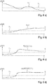
- Fig. 6a shows a pQoS profile for the Uu1 link.
- Fig. 6b shows a pQoS profile for the Uu3 link.
- Fig. 6c shows a pQoS profile for the PC5 link for direct communication between vehicles V3 and V1.
- the pQoS parameter noted along the ordinate is the receiving signal power.
- QoS parameter may be used alternatively, such as Doppler compensation information, latency information, data rate information, throughput information, packet error rate information, signal to noise ratio, and packet inter-reception time (PIR).
- PIR packet inter-reception time
- step S5 it is checked if from any of the vehicles V1 to V3 registered at the base station 210 a request for support by a ToD session has been received. If not, the program is ended in step S11. If yes, it will be checked for the vehicle demanding the ToD session, if the pQoS profile is above a threshold Th. In the scenario of Fig. 2 the vehicle V1 will send the request for a ToD session as explained above.
- the ToD application requires a minimum receiving signal power or a minimum requirement for a different pQoS parameter such as PIR time, etc.
- the base station 210 evaluates if it can establish a relaying support via other nodes (vehicles, road side units 310, traffic lights, etc.) to increase the received power.
- Fig. 6a it is seen that the pQoS profile for Uu1 link violates the minimum requirement.
- the curve for the pQoS profile drops below the threshold Th for a certain time interval, increases again and stays above the threshold Th for another time period and drops below the threshold for the rest of the pQoS profile.
- Fig. 6b depicts the Uu3 link pQoS profile.
- Fig. 6c shows a pQoS profile for the sidelink communication from vehicle V3 to V1.
- step S6 The checking of the Uu link pQoS profile for the requesting vehicle happens in step S6. If the Uu link profile fulfills the requirement, it will be decided to use the Uu link for the requested ToD session. A corresponding entry will be set in a register memory in step S10. At the same step a corresponding message is sent to the demanding vehicle V1 to inform it about this selection. If it has been found in step S6 that the pQoS profile does not fulfill the minimum requirements, it follows in step S7 the testing of the possibility of using relaying for fulfilling the minimum requirement for the requested ToD session. The base station 210 needs to know if the sidelink communication between V1 and another vehicle may be used to guarantee the minimum requirement for the ToD session. This is not always possible.
- the step S7 includes a step of calculating a combined pQoS profile out of the profiles for the Uu3 and PC5 (V3, V1) link.
- Fig. 6d shows a resulting pQoS profile for the combination of Uu3 and PC5 (V3, V1) link. As seen in Fig. 6a and 6d , where the Uu1 link profile drops below the threshold Th, the combined profile exceeds the threshold Th.
- step S8 it is checked if the combined profile for relaying might be used at the trajectory section where the Uu1 pQoS profile drops below the threshold Th. If not, the program is ended in step S11. If the result in query S8 is that both profiles complement each other, it follows in step S9 the setting of a corresponding entry in said register memory and the sending of a message to demanding vehicle V1.
- the ToD session will be invoked by vehicle V1 by sending a ToD session request message to the backend server 320 in the control center.
- Fig. 7 shows the message exchange between control center with backend server 320, the base station and the involved vehicles V1 and V3.
- the vehicle V1 in need of ToD support sends a request to base station 210 for a predicted QoS profile.
- the base station 210 answers either with the message to use the Uu link for ToD session communication if pQoS profile is good enough or answers with a message to use relaying support if not good enough.
- the vehicle V1 invokes the ToD session by sending a message to the backend server 320 in the control center.
- the backend server 320 starts sending ToD messages to the base station 210.
- the base station 210 uses the Uu link or the relaying support for exchanging the ToD messages with vehicle V1.
- the proposed method and apparatus may be implemented in various forms of hardware, software, firmware, special purpose processors, or a combination thereof.
- Special purpose processors may include application specific integrated circuits (ASICs), reduced instruction set computers (RISCs) and/or field programmable gate arrays (FPGAs).
- ASICs application specific integrated circuits
- RISCs reduced instruction set computers
- FPGAs field programmable gate arrays
- the proposed method and apparatus is implemented as a combination of hardware and software.
- the software is preferably implemented as an application program tangibly embodied on a program storage device.
- the application program may be uploaded to and executed by a machine comprising any suitable architecture.
- the machine is implemented on a computer platform having hardware such as one or more central processing units (CPU), a random access memory (RAM), and input/output (I/O) interface(s).
- CPU central processing units
- RAM random access memory
- I/O input/output
- the computer platform also includes an operating system and microinstruction code.
- the various processes and functions described herein may either be part of the microinstruction code or part of the application program (or a combination thereof), which is executed via the operating system.
- various other peripheral devices may be connected to the computer platform such as an additional data storage device and a printing device.
- the elements shown in the figures may be implemented in various forms of hardware, software or combinations thereof. Preferably, these elements are implemented in a combination of hardware and software on one or more appropriately programmed general-purpose devices, which may include a processor, memory and input/output interfaces.
- general-purpose devices which may include a processor, memory and input/output interfaces.
- the phrase "coupled" is defined to mean directly connected to or indirectly connected with through one or more intermediate components. Such intermediate components may include both hardware and software based components.
Landscapes
- Engineering & Computer Science (AREA)
- Computer Networks & Wireless Communication (AREA)
- Signal Processing (AREA)
- Quality & Reliability (AREA)
- Physics & Mathematics (AREA)
- Electromagnetism (AREA)
- Mobile Radio Communication Systems (AREA)
Priority Applications (4)
| Application Number | Priority Date | Filing Date | Title |
|---|---|---|---|
| EP20171679.2A EP3905732B1 (de) | 2020-04-27 | 2020-04-27 | Verfahren und vorrichtung zur verwaltung einer kommunikation zwischen einer basisstation eines zellularen mobilkommunikationssystems und mindestens einem beweglichen kommunikationspartner, computerprogramm, vorrichtung zur durchführung der schritte des verfahrens und fahrzeug |
| US17/224,273 US11943664B2 (en) | 2020-04-27 | 2021-04-07 | Method and apparatus for managing a communication between a base station of a cellular mobile communication system and at least one moving communication partner, computer program, apparatus for performing steps of the method, and a vehicle |
| KR1020210052260A KR102555082B1 (ko) | 2020-04-27 | 2021-04-22 | 셀룰러 모바일 통신 시스템의 기지국과 적어도 하나의 이동 통신 파트너 사이의 통신을 관리하기 위한 방법 및 장치, 컴퓨터 프로그램, 상기 방법의 단계를 수행하기 위한 장치, 및 차량 |
| CN202110459280.2A CN113645575B (zh) | 2020-04-27 | 2021-04-27 | 用于管理基站与至少一个移动通信伙伴之间的通信的方法和装置、计算机程序以及车辆 |
Applications Claiming Priority (1)
| Application Number | Priority Date | Filing Date | Title |
|---|---|---|---|
| EP20171679.2A EP3905732B1 (de) | 2020-04-27 | 2020-04-27 | Verfahren und vorrichtung zur verwaltung einer kommunikation zwischen einer basisstation eines zellularen mobilkommunikationssystems und mindestens einem beweglichen kommunikationspartner, computerprogramm, vorrichtung zur durchführung der schritte des verfahrens und fahrzeug |
Publications (2)
| Publication Number | Publication Date |
|---|---|
| EP3905732A1 true EP3905732A1 (de) | 2021-11-03 |
| EP3905732B1 EP3905732B1 (de) | 2024-04-17 |
Family
ID=70470946
Family Applications (1)
| Application Number | Title | Priority Date | Filing Date |
|---|---|---|---|
| EP20171679.2A Active EP3905732B1 (de) | 2020-04-27 | 2020-04-27 | Verfahren und vorrichtung zur verwaltung einer kommunikation zwischen einer basisstation eines zellularen mobilkommunikationssystems und mindestens einem beweglichen kommunikationspartner, computerprogramm, vorrichtung zur durchführung der schritte des verfahrens und fahrzeug |
Country Status (4)
| Country | Link |
|---|---|
| US (1) | US11943664B2 (de) |
| EP (1) | EP3905732B1 (de) |
| KR (1) | KR102555082B1 (de) |
| CN (1) | CN113645575B (de) |
Cited By (1)
| Publication number | Priority date | Publication date | Assignee | Title |
|---|---|---|---|---|
| CN114727403A (zh) * | 2022-04-25 | 2022-07-08 | 中国联合网络通信集团有限公司 | 一种上行资源块分配方法、接入网设备和用户终端 |
Families Citing this family (1)
| Publication number | Priority date | Publication date | Assignee | Title |
|---|---|---|---|---|
| EP3731204B1 (de) * | 2019-04-24 | 2024-02-21 | Volkswagen Aktiengesellschaft | Verfahren, computerprogramm, vorrichtung, fahrzeug und netzwerkkomponente zur steuerung eines manövers innerhalb einer kolonne |
Citations (5)
| Publication number | Priority date | Publication date | Assignee | Title |
|---|---|---|---|---|
| US20090117851A1 (en) * | 2004-08-11 | 2009-05-07 | National Ict Australia Limited | Quality of service seeker |
| EP3253126A1 (de) * | 2016-05-31 | 2017-12-06 | Volkswagen Aktiengesellschaft | Verfahren zur planung von übertragungsressourcen in einem mobilkommunikationssystem und basisstation, relaisstation und benutzergerätestation zur verwendung in dem verfahren |
| US20180343598A1 (en) | 2015-11-05 | 2018-11-29 | Sony Corporation | Electronic device and wireless communication method in wireless communication system |
| US20190124015A1 (en) | 2016-07-18 | 2019-04-25 | Panasonic Intellectual Property Corporation Of America | Support of quality of service for v2x transmissions |
| US20190281644A1 (en) * | 2016-11-28 | 2019-09-12 | Huawei Technologies Co., Ltd. | Base station and transmitter and relay communication devices for cellular and d2d communication |
Family Cites Families (13)
| Publication number | Priority date | Publication date | Assignee | Title |
|---|---|---|---|---|
| US6400690B1 (en) * | 1998-10-15 | 2002-06-04 | International Business Machines Corporation | Dual map system for navigation and wireless communication |
| US7957757B2 (en) | 2007-07-05 | 2011-06-07 | Qualcomm Incorporated | Open loop power offset update |
| US8548463B2 (en) * | 2011-10-18 | 2013-10-01 | Alcatel Lucent | PCRN roaming agreement |
| CN107534482B (zh) | 2015-05-15 | 2021-01-29 | 索尼公司 | 移动通信系统、通信终端和方法 |
| CN105049872A (zh) | 2015-05-19 | 2015-11-11 | 上海交通大学 | 蜂窝网中车载移动用户视频业务的缓存管理方法 |
| CN105307216B (zh) | 2015-06-26 | 2019-02-12 | 哈尔滨工业大学深圳研究生院 | 一种基于lte车联网的无线资源分配方法 |
| CN206002819U (zh) | 2016-09-18 | 2017-03-08 | 京东方科技集团股份有限公司 | 阵列基板及显示器件 |
| JP2020529757A (ja) | 2017-08-08 | 2020-10-08 | アイピーコム ゲーエムベーハー ウント コー. カーゲー | 異常な高度にあるデバイスからの干渉の低減 |
| JP6801619B2 (ja) * | 2017-09-25 | 2020-12-16 | 株式会社デンソー | データ転送経路算出装置およびデータ転送端末 |
| EP3614770B8 (de) | 2018-08-23 | 2024-04-03 | Volkswagen Aktiengesellschaft | Fahrzeug, vorrichtungen, verfahren und computerprogramme für einen mobilen sender-empfänger und einen verwaltenden mobilen sender-empfänger zur zuweisung von funkressourcen |
| EP3621274B1 (de) | 2018-09-04 | 2022-04-20 | Volkswagen Aktiengesellschaft | Verfahren zur vorhersage einer dienstqualität für eine kommunikation zwischen mindestens zwei sich bewegenden kommunikationspartnern, vorrichtung zur durchführung der schritte des verfahrens, fahrzeug, backend-server und computerprogramm |
| EP3634017B1 (de) | 2018-10-02 | 2024-03-06 | Volkswagen Aktiengesellschaft | Vorhersage der servicequalität für eine kommunikationsverbindung eines geräts eines fahrzeug entlang eines geplanten wegs |
| KR102527813B1 (ko) | 2018-10-05 | 2023-05-02 | 삼성전자주식회사 | 차량 통신 서비스를 위한 정보를 제공하는 방법 및 장치 |
-
2020
- 2020-04-27 EP EP20171679.2A patent/EP3905732B1/de active Active
-
2021
- 2021-04-07 US US17/224,273 patent/US11943664B2/en active Active
- 2021-04-22 KR KR1020210052260A patent/KR102555082B1/ko active IP Right Grant
- 2021-04-27 CN CN202110459280.2A patent/CN113645575B/zh active Active
Patent Citations (5)
| Publication number | Priority date | Publication date | Assignee | Title |
|---|---|---|---|---|
| US20090117851A1 (en) * | 2004-08-11 | 2009-05-07 | National Ict Australia Limited | Quality of service seeker |
| US20180343598A1 (en) | 2015-11-05 | 2018-11-29 | Sony Corporation | Electronic device and wireless communication method in wireless communication system |
| EP3253126A1 (de) * | 2016-05-31 | 2017-12-06 | Volkswagen Aktiengesellschaft | Verfahren zur planung von übertragungsressourcen in einem mobilkommunikationssystem und basisstation, relaisstation und benutzergerätestation zur verwendung in dem verfahren |
| US20190124015A1 (en) | 2016-07-18 | 2019-04-25 | Panasonic Intellectual Property Corporation Of America | Support of quality of service for v2x transmissions |
| US20190281644A1 (en) * | 2016-11-28 | 2019-09-12 | Huawei Technologies Co., Ltd. | Base station and transmitter and relay communication devices for cellular and d2d communication |
Non-Patent Citations (1)
| Title |
|---|
| PANTHANGI M RAMYA ET AL: "Online Learning Framework for V2V Link Quality Prediction", 2019 IEEE GLOBAL COMMUNICATIONS CONFERENCE (GLOBECOM), IEEE, 9 December 2019 (2019-12-09), pages 1 - 6, XP033721985, DOI: 10.1109/GLOBECOM38437.2019.9013146 * |
Cited By (1)
| Publication number | Priority date | Publication date | Assignee | Title |
|---|---|---|---|---|
| CN114727403A (zh) * | 2022-04-25 | 2022-07-08 | 中国联合网络通信集团有限公司 | 一种上行资源块分配方法、接入网设备和用户终端 |
Also Published As
| Publication number | Publication date |
|---|---|
| EP3905732B1 (de) | 2024-04-17 |
| CN113645575A (zh) | 2021-11-12 |
| KR20210132610A (ko) | 2021-11-04 |
| CN113645575B (zh) | 2024-07-09 |
| US20210337431A1 (en) | 2021-10-28 |
| KR102555082B1 (ko) | 2023-07-12 |
| US11943664B2 (en) | 2024-03-26 |
Similar Documents
| Publication | Publication Date | Title |
|---|---|---|
| US11223969B2 (en) | Method and apparatus for predicting a quality of service for the communication about at least one communication link of at least one communication device, communication service prediction server and computer program | |
| US11129002B2 (en) | Method for supporting a first mobile station to predict the channel quality for a planned decentralized wireless communication to a communication partner station, mobile station, and transportation vehicle | |
| KR102283247B1 (ko) | 적어도 2 개의 이동 통신 파트너 간의 통신을 위한 서비스 품질을 예측하기 위한 방법, 이러한 방법의 단계들을 수행하기 위한 장치, 차량, 백엔드 서버 및 컴퓨터 프로그램 | |
| GB2574908A (en) | Network and control thereof | |
| US10271246B2 (en) | Method for transferring a mobile network subscriber station in a handover process in a mobile network, mobile network subscriber station, and mobile network management unit for use in the method and vehicle | |
| US10764808B2 (en) | Method for performing a handover process for a mobile radio network terminal in a mobile radio network, corresponding apparatuses for performing the method, transportation vehicle and core network management device, and corresponding computer programs | |
| US11323898B2 (en) | Method for monitoring the quality of a data connection, subscriber station, and network management unit for use in the method | |
| EP3742767B1 (de) | Verfahren zur vorhersage der dienstqualität einer kommunikation zwischen zwei kommunikationspartnern, einer davon möglicherweise ein bewegliches fahrzeug; vorrichtung zur ausführung der verfahrensschritte und computerprogram | |
| US10916128B2 (en) | Method for data communication between at least two participants of a wireless communication system, corresponding control unit and transportation vehicle equipped with a control unit, and computer program | |
| US11835964B2 (en) | Method for determining a high-density platooning driving maneuver, apparatus, vehicle and computer program | |
| US11943664B2 (en) | Method and apparatus for managing a communication between a base station of a cellular mobile communication system and at least one moving communication partner, computer program, apparatus for performing steps of the method, and a vehicle | |
| US12021575B2 (en) | Method for predictively estimating the transmission conditions for a communication between two communication partners, device for carrying out the method steps of the method, vehicle and computer program | |
| EP3621323B1 (de) | Verfahren zum einrichten einer abstrahierten kanaldarstellung für eine kommunikation zwischen mindestens zwei beweglichen kommunikationspartnern, vorrichtung zum durchführen eines verfahrensschrittes, fahrzeug und computerprogramm | |
| EP4228290A1 (de) | Drahtloskommunikationsvorrichtung für ein fahrzeug und drahtloskommunikationsverfahren | |
| CN115696256A (zh) | 车联网消息自适应发送方法、装置、设备及存储介质 |
Legal Events
| Date | Code | Title | Description |
|---|---|---|---|
| PUAI | Public reference made under article 153(3) epc to a published international application that has entered the european phase |
Free format text: ORIGINAL CODE: 0009012 |
|
| STAA | Information on the status of an ep patent application or granted ep patent |
Free format text: STATUS: THE APPLICATION HAS BEEN PUBLISHED |
|
| AK | Designated contracting states |
Kind code of ref document: A1 Designated state(s): AL AT BE BG CH CY CZ DE DK EE ES FI FR GB GR HR HU IE IS IT LI LT LU LV MC MK MT NL NO PL PT RO RS SE SI SK SM TR |
|
| B565 | Issuance of search results under rule 164(2) epc |
Effective date: 20201007 |
|
| STAA | Information on the status of an ep patent application or granted ep patent |
Free format text: STATUS: REQUEST FOR EXAMINATION WAS MADE |
|
| 17P | Request for examination filed |
Effective date: 20220503 |
|
| RBV | Designated contracting states (corrected) |
Designated state(s): AL AT BE BG CH CY CZ DE DK EE ES FI FR GB GR HR HU IE IS IT LI LT LU LV MC MK MT NL NO PL PT RO RS SE SI SK SM TR |
|
| STAA | Information on the status of an ep patent application or granted ep patent |
Free format text: STATUS: EXAMINATION IS IN PROGRESS |
|
| 17Q | First examination report despatched |
Effective date: 20230713 |
|
| RIC1 | Information provided on ipc code assigned before grant |
Ipc: H04W 88/04 20090101ALN20231130BHEP Ipc: H04W 28/26 20090101ALI20231130BHEP Ipc: H04W 16/18 20090101ALI20231130BHEP Ipc: H04W 40/12 20090101ALI20231130BHEP Ipc: H04L 45/122 20220101ALI20231130BHEP Ipc: H04W 4/40 20180101AFI20231130BHEP |
|
| GRAP | Despatch of communication of intention to grant a patent |
Free format text: ORIGINAL CODE: EPIDOSNIGR1 |
|
| STAA | Information on the status of an ep patent application or granted ep patent |
Free format text: STATUS: GRANT OF PATENT IS INTENDED |
|
| RIC1 | Information provided on ipc code assigned before grant |
Ipc: H04W 88/04 20090101ALN20231221BHEP Ipc: H04W 28/26 20090101ALI20231221BHEP Ipc: H04W 16/18 20090101ALI20231221BHEP Ipc: H04W 40/12 20090101ALI20231221BHEP Ipc: H04L 45/122 20220101ALI20231221BHEP Ipc: H04W 4/40 20180101AFI20231221BHEP |
|
| INTG | Intention to grant announced |
Effective date: 20240109 |
|
| P01 | Opt-out of the competence of the unified patent court (upc) registered |
Effective date: 20240112 |
|
| GRAS | Grant fee paid |
Free format text: ORIGINAL CODE: EPIDOSNIGR3 |
|
| GRAA | (expected) grant |
Free format text: ORIGINAL CODE: 0009210 |
|
| STAA | Information on the status of an ep patent application or granted ep patent |
Free format text: STATUS: THE PATENT HAS BEEN GRANTED |
|
| AK | Designated contracting states |
Kind code of ref document: B1 Designated state(s): AL AT BE BG CH CY CZ DE DK EE ES FI FR GB GR HR HU IE IS IT LI LT LU LV MC MK MT NL NO PL PT RO RS SE SI SK SM TR |
|
| REG | Reference to a national code |
Ref country code: GB Ref legal event code: FG4D |
|
| REG | Reference to a national code |
Ref country code: CH Ref legal event code: EP |
|
| REG | Reference to a national code |
Ref country code: IE Ref legal event code: FG4D Ref country code: DE Ref legal event code: R096 Ref document number: 602020029011 Country of ref document: DE |
|
| PGFP | Annual fee paid to national office [announced via postgrant information from national office to epo] |
Ref country code: GB Payment date: 20240423 Year of fee payment: 5 |
|
| PGFP | Annual fee paid to national office [announced via postgrant information from national office to epo] |
Ref country code: DE Payment date: 20240430 Year of fee payment: 5 |
|
| PGFP | Annual fee paid to national office [announced via postgrant information from national office to epo] |
Ref country code: FR Payment date: 20240430 Year of fee payment: 5 |
|
| REG | Reference to a national code |
Ref country code: LT Ref legal event code: MG9D |
|
| REG | Reference to a national code |
Ref country code: NL Ref legal event code: MP Effective date: 20240417 |
|
| REG | Reference to a national code |
Ref country code: AT Ref legal event code: MK05 Ref document number: 1678409 Country of ref document: AT Kind code of ref document: T Effective date: 20240417 |