EP3905511A1 - Drive device for dynamo-electric machine, and method for driving - Google Patents
Drive device for dynamo-electric machine, and method for driving Download PDFInfo
- Publication number
- EP3905511A1 EP3905511A1 EP19906074.0A EP19906074A EP3905511A1 EP 3905511 A1 EP3905511 A1 EP 3905511A1 EP 19906074 A EP19906074 A EP 19906074A EP 3905511 A1 EP3905511 A1 EP 3905511A1
- Authority
- EP
- European Patent Office
- Prior art keywords
- dynamo
- permanent magnet
- electric machine
- temperature
- magnet synchronous
- Prior art date
- Legal status (The legal status is an assumption and is not a legal conclusion. Google has not performed a legal analysis and makes no representation as to the accuracy of the status listed.)
- Granted
Links
Images





Classifications
-
- H—ELECTRICITY
- H02—GENERATION; CONVERSION OR DISTRIBUTION OF ELECTRIC POWER
- H02P—CONTROL OR REGULATION OF ELECTRIC MOTORS, ELECTRIC GENERATORS OR DYNAMO-ELECTRIC CONVERTERS; CONTROLLING TRANSFORMERS, REACTORS OR CHOKE COILS
- H02P29/00—Arrangements for regulating or controlling electric motors, appropriate for both AC and DC motors
- H02P29/60—Controlling or determining the temperature of the motor or of the drive
-
- B—PERFORMING OPERATIONS; TRANSPORTING
- B60—VEHICLES IN GENERAL
- B60L—PROPULSION OF ELECTRICALLY-PROPELLED VEHICLES; SUPPLYING ELECTRIC POWER FOR AUXILIARY EQUIPMENT OF ELECTRICALLY-PROPELLED VEHICLES; ELECTRODYNAMIC BRAKE SYSTEMS FOR VEHICLES IN GENERAL; MAGNETIC SUSPENSION OR LEVITATION FOR VEHICLES; MONITORING OPERATING VARIABLES OF ELECTRICALLY-PROPELLED VEHICLES; ELECTRIC SAFETY DEVICES FOR ELECTRICALLY-PROPELLED VEHICLES
- B60L15/00—Methods, circuits, or devices for controlling the traction-motor speed of electrically-propelled vehicles
- B60L15/02—Methods, circuits, or devices for controlling the traction-motor speed of electrically-propelled vehicles characterised by the form of the current used in the control circuit
- B60L15/025—Methods, circuits, or devices for controlling the traction-motor speed of electrically-propelled vehicles characterised by the form of the current used in the control circuit using field orientation; Vector control; Direct Torque Control [DTC]
-
- B—PERFORMING OPERATIONS; TRANSPORTING
- B60—VEHICLES IN GENERAL
- B60L—PROPULSION OF ELECTRICALLY-PROPELLED VEHICLES; SUPPLYING ELECTRIC POWER FOR AUXILIARY EQUIPMENT OF ELECTRICALLY-PROPELLED VEHICLES; ELECTRODYNAMIC BRAKE SYSTEMS FOR VEHICLES IN GENERAL; MAGNETIC SUSPENSION OR LEVITATION FOR VEHICLES; MONITORING OPERATING VARIABLES OF ELECTRICALLY-PROPELLED VEHICLES; ELECTRIC SAFETY DEVICES FOR ELECTRICALLY-PROPELLED VEHICLES
- B60L15/00—Methods, circuits, or devices for controlling the traction-motor speed of electrically-propelled vehicles
- B60L15/20—Methods, circuits, or devices for controlling the traction-motor speed of electrically-propelled vehicles for control of the vehicle or its driving motor to achieve a desired performance, e.g. speed, torque, programmed variation of speed
- B60L15/2045—Methods, circuits, or devices for controlling the traction-motor speed of electrically-propelled vehicles for control of the vehicle or its driving motor to achieve a desired performance, e.g. speed, torque, programmed variation of speed for optimising the use of energy
-
- B—PERFORMING OPERATIONS; TRANSPORTING
- B60—VEHICLES IN GENERAL
- B60L—PROPULSION OF ELECTRICALLY-PROPELLED VEHICLES; SUPPLYING ELECTRIC POWER FOR AUXILIARY EQUIPMENT OF ELECTRICALLY-PROPELLED VEHICLES; ELECTRODYNAMIC BRAKE SYSTEMS FOR VEHICLES IN GENERAL; MAGNETIC SUSPENSION OR LEVITATION FOR VEHICLES; MONITORING OPERATING VARIABLES OF ELECTRICALLY-PROPELLED VEHICLES; ELECTRIC SAFETY DEVICES FOR ELECTRICALLY-PROPELLED VEHICLES
- B60L9/00—Electric propulsion with power supply external to the vehicle
- B60L9/16—Electric propulsion with power supply external to the vehicle using AC induction motors
- B60L9/18—Electric propulsion with power supply external to the vehicle using AC induction motors fed from DC supply lines
- B60L9/22—Electric propulsion with power supply external to the vehicle using AC induction motors fed from DC supply lines polyphase motors
-
- H—ELECTRICITY
- H02—GENERATION; CONVERSION OR DISTRIBUTION OF ELECTRIC POWER
- H02P—CONTROL OR REGULATION OF ELECTRIC MOTORS, ELECTRIC GENERATORS OR DYNAMO-ELECTRIC CONVERTERS; CONTROLLING TRANSFORMERS, REACTORS OR CHOKE COILS
- H02P21/00—Arrangements or methods for the control of electric machines by vector control, e.g. by control of field orientation
- H02P21/02—Arrangements or methods for the control of electric machines by vector control, e.g. by control of field orientation specially adapted for optimising the efficiency at low load
-
- H—ELECTRICITY
- H02—GENERATION; CONVERSION OR DISTRIBUTION OF ELECTRIC POWER
- H02P—CONTROL OR REGULATION OF ELECTRIC MOTORS, ELECTRIC GENERATORS OR DYNAMO-ELECTRIC CONVERTERS; CONTROLLING TRANSFORMERS, REACTORS OR CHOKE COILS
- H02P5/00—Arrangements specially adapted for regulating or controlling the speed or torque of two or more electric motors
- H02P5/74—Arrangements specially adapted for regulating or controlling the speed or torque of two or more electric motors controlling two or more AC dynamo-electric motors
-
- B—PERFORMING OPERATIONS; TRANSPORTING
- B60—VEHICLES IN GENERAL
- B60L—PROPULSION OF ELECTRICALLY-PROPELLED VEHICLES; SUPPLYING ELECTRIC POWER FOR AUXILIARY EQUIPMENT OF ELECTRICALLY-PROPELLED VEHICLES; ELECTRODYNAMIC BRAKE SYSTEMS FOR VEHICLES IN GENERAL; MAGNETIC SUSPENSION OR LEVITATION FOR VEHICLES; MONITORING OPERATING VARIABLES OF ELECTRICALLY-PROPELLED VEHICLES; ELECTRIC SAFETY DEVICES FOR ELECTRICALLY-PROPELLED VEHICLES
- B60L2200/00—Type of vehicles
- B60L2200/26—Rail vehicles
-
- B—PERFORMING OPERATIONS; TRANSPORTING
- B60—VEHICLES IN GENERAL
- B60L—PROPULSION OF ELECTRICALLY-PROPELLED VEHICLES; SUPPLYING ELECTRIC POWER FOR AUXILIARY EQUIPMENT OF ELECTRICALLY-PROPELLED VEHICLES; ELECTRODYNAMIC BRAKE SYSTEMS FOR VEHICLES IN GENERAL; MAGNETIC SUSPENSION OR LEVITATION FOR VEHICLES; MONITORING OPERATING VARIABLES OF ELECTRICALLY-PROPELLED VEHICLES; ELECTRIC SAFETY DEVICES FOR ELECTRICALLY-PROPELLED VEHICLES
- B60L2220/00—Electrical machine types; Structures or applications thereof
- B60L2220/10—Electrical machine types
- B60L2220/14—Synchronous machines
-
- B—PERFORMING OPERATIONS; TRANSPORTING
- B60—VEHICLES IN GENERAL
- B60L—PROPULSION OF ELECTRICALLY-PROPELLED VEHICLES; SUPPLYING ELECTRIC POWER FOR AUXILIARY EQUIPMENT OF ELECTRICALLY-PROPELLED VEHICLES; ELECTRODYNAMIC BRAKE SYSTEMS FOR VEHICLES IN GENERAL; MAGNETIC SUSPENSION OR LEVITATION FOR VEHICLES; MONITORING OPERATING VARIABLES OF ELECTRICALLY-PROPELLED VEHICLES; ELECTRIC SAFETY DEVICES FOR ELECTRICALLY-PROPELLED VEHICLES
- B60L2220/00—Electrical machine types; Structures or applications thereof
- B60L2220/40—Electrical machine applications
- B60L2220/42—Electrical machine applications with use of more than one motor
-
- B—PERFORMING OPERATIONS; TRANSPORTING
- B60—VEHICLES IN GENERAL
- B60L—PROPULSION OF ELECTRICALLY-PROPELLED VEHICLES; SUPPLYING ELECTRIC POWER FOR AUXILIARY EQUIPMENT OF ELECTRICALLY-PROPELLED VEHICLES; ELECTRODYNAMIC BRAKE SYSTEMS FOR VEHICLES IN GENERAL; MAGNETIC SUSPENSION OR LEVITATION FOR VEHICLES; MONITORING OPERATING VARIABLES OF ELECTRICALLY-PROPELLED VEHICLES; ELECTRIC SAFETY DEVICES FOR ELECTRICALLY-PROPELLED VEHICLES
- B60L2240/00—Control parameters of input or output; Target parameters
- B60L2240/40—Drive Train control parameters
- B60L2240/42—Drive Train control parameters related to electric machines
- B60L2240/423—Torque
-
- B—PERFORMING OPERATIONS; TRANSPORTING
- B60—VEHICLES IN GENERAL
- B60L—PROPULSION OF ELECTRICALLY-PROPELLED VEHICLES; SUPPLYING ELECTRIC POWER FOR AUXILIARY EQUIPMENT OF ELECTRICALLY-PROPELLED VEHICLES; ELECTRODYNAMIC BRAKE SYSTEMS FOR VEHICLES IN GENERAL; MAGNETIC SUSPENSION OR LEVITATION FOR VEHICLES; MONITORING OPERATING VARIABLES OF ELECTRICALLY-PROPELLED VEHICLES; ELECTRIC SAFETY DEVICES FOR ELECTRICALLY-PROPELLED VEHICLES
- B60L2240/00—Control parameters of input or output; Target parameters
- B60L2240/40—Drive Train control parameters
- B60L2240/42—Drive Train control parameters related to electric machines
- B60L2240/425—Temperature
-
- B—PERFORMING OPERATIONS; TRANSPORTING
- B60—VEHICLES IN GENERAL
- B60L—PROPULSION OF ELECTRICALLY-PROPELLED VEHICLES; SUPPLYING ELECTRIC POWER FOR AUXILIARY EQUIPMENT OF ELECTRICALLY-PROPELLED VEHICLES; ELECTRODYNAMIC BRAKE SYSTEMS FOR VEHICLES IN GENERAL; MAGNETIC SUSPENSION OR LEVITATION FOR VEHICLES; MONITORING OPERATING VARIABLES OF ELECTRICALLY-PROPELLED VEHICLES; ELECTRIC SAFETY DEVICES FOR ELECTRICALLY-PROPELLED VEHICLES
- B60L2240/00—Control parameters of input or output; Target parameters
- B60L2240/40—Drive Train control parameters
- B60L2240/42—Drive Train control parameters related to electric machines
- B60L2240/429—Current
-
- Y—GENERAL TAGGING OF NEW TECHNOLOGICAL DEVELOPMENTS; GENERAL TAGGING OF CROSS-SECTIONAL TECHNOLOGIES SPANNING OVER SEVERAL SECTIONS OF THE IPC; TECHNICAL SUBJECTS COVERED BY FORMER USPC CROSS-REFERENCE ART COLLECTIONS [XRACs] AND DIGESTS
- Y02—TECHNOLOGIES OR APPLICATIONS FOR MITIGATION OR ADAPTATION AGAINST CLIMATE CHANGE
- Y02T—CLIMATE CHANGE MITIGATION TECHNOLOGIES RELATED TO TRANSPORTATION
- Y02T10/00—Road transport of goods or passengers
- Y02T10/60—Other road transportation technologies with climate change mitigation effect
- Y02T10/64—Electric machine technologies in electromobility
-
- Y—GENERAL TAGGING OF NEW TECHNOLOGICAL DEVELOPMENTS; GENERAL TAGGING OF CROSS-SECTIONAL TECHNOLOGIES SPANNING OVER SEVERAL SECTIONS OF THE IPC; TECHNICAL SUBJECTS COVERED BY FORMER USPC CROSS-REFERENCE ART COLLECTIONS [XRACs] AND DIGESTS
- Y02—TECHNOLOGIES OR APPLICATIONS FOR MITIGATION OR ADAPTATION AGAINST CLIMATE CHANGE
- Y02T—CLIMATE CHANGE MITIGATION TECHNOLOGIES RELATED TO TRANSPORTATION
- Y02T10/00—Road transport of goods or passengers
- Y02T10/60—Other road transportation technologies with climate change mitigation effect
- Y02T10/72—Electric energy management in electromobility
Definitions
- the present invention relates to a drive device for a dynamo-electric machine, and is particularly suitable as a drive device of a permanent magnet synchronous motor for a railroad vehicle.
- Patient Literature 1 proposes a control device for a railroad vehicle which has a configuration in which an AC circuit breaker is provided between a power conversion device and each of a plurality of dynamo-electric machines and a circuit breaker control unit for individually controlling the opening and closing of the AC circuit breaker based on an operation control command from a cab is provided and which is driven under operating conditions where the dynamo-electric machine is highly efficient by reducing the number of dynamo-electric machines to be driven in accordance with torque necessary for the vehicle.
- Patient Literature 2 proposes an electric vehicle control device in which when the temperature of a dynamo-electric machine exceeds or is determined to exceed a preset allowance value, in order to change into a torque command suppressing the temperature of the dynamo-electric machine within the allowance value, a dynamo-electric machine whose torque is supplemented is selected in the order in which the temperature has a margin among the other dynamo-electric machines, and the shortage of the output torque in the dynamo-electric machine where the temperature rises is compensated.
- Patent Literature 1 discloses a technique for improving efficiency by driving a dynamo-electric machine at a point where the efficiency of the dynamo-electric machine is enhanced while switching the number of dynamo-electric machines using a circuit breaker. Then, although the dynamo-electric machine is selectively driven so that the temperature of the dynamo-electric machine to be driven is not biased against the temperature fluctuation of the dynamo-electric machine, only by operating the dynamo-electric machine with a low temperature to equalize the losses of a plurality of dynamo-electric machines, the losses themselves generated in the plurality of dynamo-electric machines are not reduced, and there is room for improvement to realize high efficiency.
- Patent Literature 1 if the technique described in Patent Literature 1 is applied to a permanent magnet synchronous motor, since a rotor is provided with a permanent magnet, an iron loss occurs during the free-run of the rotor when an AC circuit breaker is opened, and there is a problem that the temperature of the permanent magnet synchronous motor rises.
- the magnetic flux is weakened by weaker field control during the normal control period, the magnetic flux is not weakened during the free-run at the time of opening, and thus the iron loss increases.
- heat generation possibly increases in the open period rather than in the normal control period, and there is a problem in terms of cooling performance and reliability.
- Patent Literature 2 discloses a technique in which when the temperature of a dynamo-electric machine exceeds or is determined to exceed a preset allowance value, a dynamo-electric machine is selected in the order in which the temperature has a margin, and torque is supplemented.
- An object of the present invention is to improve the efficiency of a system for obtaining, when driving and controlling a plurality of dynamo-electric machines, power by the plurality of dynamo-electric machines by individually changing a torque operation amount in consideration of the temperature dependency of the dynamo-electric machines.
- the present invention is provided with a plurality of voltage generation devices for outputting arbitrary voltages to a plurality of dynamo-electric machines and a control device for adjusting the output voltages of the voltage generation devices, and the control device acquires temperature information of each of the plurality of dynamo-electric machines, selects a relatively highly-efficient dynamo-electric machine from among the plurality of dynamo-electric machines based on each temperature information, and increases a torque command value for the selected dynamo-electric machine relative to the plurality of other dynamo-electric machines.
- the high efficiency of the drive system can be realized and power consumption can be further reduced by individually changing the output torque of the plurality of dynamo-electric machines in consideration of the temperature dependency of the efficiency of the dynamo-electric machines.
- Fig. 1 is a diagram for showing an example of functional blocks of a drive device for a permanent magnet synchronous motor according to a first embodiment.
- a configuration for adjusting a torque command value is shown as functional blocks so that the total efficiency of a drive system configured using plural permanent magnet synchronous motors is enhanced based on temperature information of each permanent magnet synchronous motor.
- Fig. 1 Although two permanent magnet synchronous motors 4a and 4b are shown in Fig. 1 , the number of permanent magnet synchronous motors is not limited to two as long as plural motors are used. Hereinafter, components and functions related to two motors are distinguished by using subscripts a and b so as to correspond to two motors.
- a current between the overhead wire side and the permanent magnet synchronous motor side can be cut off by a high-speed circuit breaker 23 and a line breaker 22.
- an LC filter circuit for smoothing a DC current that is configured using a filter reactor 21 and a filter capacitor 20 is provided between voltage generation devices 3a and 3b and the overhead wire 25.
- a control device for drive control of the permanent magnet synchronous motors includes an integrated control unit 1 and sub control units 2a and 2b. Based on switching commands from the sub control units 2a and 2b, the voltage generation devices 3a and 3b output voltages, and obtain power by allowing the permanent magnet synchronous motors 4a and 4b to output predetermined torque.
- a torque calculation unit 12 included in the integrated control unit 1 outputs torque command values ⁇ m1 * and ⁇ m2 * to be generated in the permanent magnet synchronous motors 4a and 4b to the sub control units 2a and 2b, respectively, in accordance with a power command ⁇ m0 * or a control mode switching command from a higher-level system control unit (not shown in the drawing).
- Control programs for driving and controlling the permanent magnet synchronous motors 4a and 4b connected as loads are installed in the sub control units 2a and 2b.
- the sub control units 2a and 2b output switching commands SW 1 and SW 2 for outputting predetermined torque from the permanent magnet synchronous motors 4a and 4b.
- the voltage generation devices 3a and 3b perform switching control in response to the switching commands SW 1 and SW 2 and output voltages.
- Fig. 1 shows only the minimum functional blocks necessary for the first embodiment, and a power converter configured using power devices such as a driving transistor such as an IGBT (Insulated Gate Bipora Transistor) and a diode and a control configuration for the power converter are shown using the block diagrams of the voltage generation devices 3a and 3b, and detailed illustration thereof is omitted.
- a driving transistor such as an IGBT (Insulated Gate Bipora Transistor)
- IGBT Insulated Gate Bipora Transistor
- the permanent magnet synchronous motors 4a and 4b generate rotational torque by magnet torque generated by attraction and repulsion between a magnetic pole of a rotational magnetic field generated on the stator side by application of a three-phase AC voltage and a magnetic pole of a permanent magnet of a rotor, and reluctance torque generated by attraction force between the magnetic pole of the rotational magnetic field of the stator and a magnetic salient pole of the rotor.
- Current detectors 5a and 5b detect waveforms of three-phase currents I u1 , I v1 , and I w1 and I u2 , I v2 , and I w2 of the U-phase, V-phase, and W-phase flowing in the permanent magnet synchronous motors 4a and 4b, respectively.
- the current detectors 5a and 5b it is not always necessary for the current detectors 5a and 5b to detect the currents of all the three phases, and any two phases among the three phases may be detected, and the remaining one phase may be obtained by calculation on the assumption that the three-phase currents are in an equilibrium state.
- AC contactors 6a and 6b are provided between the voltage generation devices 3a and 3b and the permanent magnet synchronous motors 4a and 4b, and cut off the current when an abnormality occurs.
- the AC contactors 6a and 6b open and close in accordance with control signals (not shown in the drawing) output from the integrated control unit 1 or the sub control units 2a and 2b.
- the sub control units 2a and 2b estimate temperature information T1 ⁇ and T2 ⁇ of the permanent magnet synchronous motors 4a and 4b, respectively, by using the current detection values of the current detectors 5a and 5b, and transmit the same to the integrated control unit 1.
- Fig. 2 shows a configuration in which temperature detectors 40a and 40b are installed in the permanent magnet synchronous motors 4a and 4b to detect the temperature information T1 ⁇ and T2 ⁇ .
- a frame temperature, a winding temperature, a permanent magnet temperature, or the like may be detected.
- Losses generated in the permanent magnet synchronous motor can be largely classified into a copper loss, a mechanical loss, and an iron loss.
- the input electric power is P in
- the output electric power is P out
- the torque is ⁇ m
- the copper loss is W s
- the iron loss is W i
- the mechanical loss is W m
- the angular frequency of the mechanical angle of the dynamo-electric machine is ⁇ m
- the efficiency n of the permanent magnet synchronous motor is represented by Equation (1) .
- Equation (2) the torque ⁇ m of the permanent magnet synchronous motor is represented by Equation (2).
- m is the number of phases
- P m is the number of pole pairs
- K e is a magnet magnetic flux (power generation constant)
- I d is a d-axis current
- I q is a q-axis current
- L d is a d-axis inductance
- L q is a q-axis inductance.
- Equation (2) The first term in Equation (2) is the above-described magnet torque (torque generated by attraction and repulsion between the magnetic pole of the rotational magnetic field and the magnetic pole of the permanent magnet of the rotor), and the second term in Equation (2) is the above-described reluctance torque (torque generated by attraction force between the magnetic pole of the rotational magnetic field of the stator and the magnetic salient pole of the rotor).
- the magnet torque is determined by the product of the magnet magnetic flux K e and the q-axis current I q , the magnet torque fluctuates due to the influence of the fluctuation of the magnet magnetic flux K e , and the output torque increases or decreases.
- a demagnetization of -0.1%/°C of the permanent magnet means that when the temperature rises by 10°C, the magnet magnetic flux K e decreases by 1%. That is, it is often considered that the lowtemperature condition in which the magnet magnetic flux increases results in a more highly efficient operation because the output torque of molecules in Equation (1) increases.
- the inventors focused on the temperature dependency of the loss indicated by the denominator of Equation (1) based on detailed study, and found that the permanent magnet synchronous motor with a low temperature does not simply becomes high efficiency, but becomes high efficiency in different operation regions at low and high temperatures depending on the operating conditions of torque and frequency.
- the copper loss W s is a loss generated in a stator winding, and can be calculated from the current value flowing in the permanent magnet synchronous motor and the resistance value. Regarding the temperature dependency of the copper loss W s , since the resistance value is changed in accordance with the temperature coefficient of a material used for the stator winding, the resistance value increases and the copper loss W s tends to increase as the temperature rises.
- the mechanical loss W m is generated by a pressure loss due to a cooling fan provided in the rotor, friction of a bearing supporting the rotor at a frame of the permanent magnet synchronous motor, or the like, and can be generally calculated as a function of a drive frequency.
- a temperature dependency of the mechanical loss W m strictly speaking, although there is a change in the viscosity of grease used for a bearing, the change can be ignored in the dynamo-electric machine for railroad vehicles. Therefore, the mechanical loss W m of the dynamo-electric machine for railroad vehicles is often treated as not being affected by temperature.
- the iron loss W i is a magnetic loss corresponding to the area of a hysteresis loop when the magnetic flux in a magnetic material used for a stator core or a rotor core is changed by applying an AC magnetic field, and is defined as the sum of a hysteresis loss and an eddy current loss and can be generally calculated as a function of magnetic flux density and a frequency.
- the temperature dependency of the iron loss W i the magnet magnetic flux itself largely affecting the iron loss in the permanent magnet synchronous motor has temperature dependency, and demagnetizes at, for example, about -0.1%/°C when the temperature rises as described above.
- the hysteresis loss in the iron loss W i is often considered to have substantially no temperature dependency.
- the electric resistance of the iron core increases due to the temperature rise, the eddy current loss tends to decrease. Therefore, the iron loss W i in the permanent magnet synchronous motor tends to decrease as the temperature becomes higher.
- the loss in the permanent magnet synchronous motor when the temperature is low, the copper loss decreases and the iron loss increases, whereas when the temperature is high, the copper loss increases and the iron loss decreases. That is, since the copper loss and the iron loss have a trade-off relationship with respect to the temperature, when considering a change in the loss at the time of temperature change under certain operating conditions, the loss as a dynamo-electric machine differently decreases under low or high temperature conditions depending on the ratio of the iron loss to the copper loss.
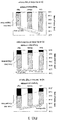
- Figs. 3 are diagrams each showing the change characteristics of the ratio of the copper loss to the iron loss when the permanent magnet synchronous motors are driven at the same rotational speed and the torque and the temperature are changed.
- Figs. 3(a), 3(b), and 3(c) show calculation results by magnetic field analysis at the time of high torque, at the time of middle torque, and at the time of low torque, respectively, and the current value is adjusted so that the output torque becomes the same even when the temperature is changed.
- the values in each drawing are normalized by the loss under the temperature condition where the total of the copper loss and the iron loss is maximized under each condition. Note that the resistance and the magnet temperature are assumed to be similarly changed.
- the condition at the time of middle torque is, as shown in Fig. 3(b) , a condition where the load torque becomes smaller and the current becomes smaller than those in Fig. 3(a) , and thus when the temperature of the dynamo-electric machine is higher, the efficiency becomes slightly higher.
- the torque command value of the permanent magnet synchronous motor with a high temperature is intentionally increased, whereas the torque command value of the permanent magnet synchronous motor with a low temperature is decreased, so that it can be understood that the permanent magnet synchronous motors can be driven with high efficiency as a whole.
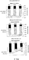
- Figs. 4 are diagrams each showing the change characteristics of the ratio of the copper loss to the iron loss when the permanent magnet synchronous motors are driven with the same torque and the rotational speed and the temperature are changed.
- Figs. 4(a), 4(b), and 4(c) show calculation results by magnetic field analysis in a low-speed range, in a medium-speed range, and in a high-speed range, respectively, and the current is adjusted so that the output torque becomes the same even when the temperature is changed.
- the values in each drawing are normalized by the loss under the temperature condition where the total of the copper loss and the iron loss is maximized under each condition. Note that the resistance and the magnet temperature are assumed to be similarly changed.
- the iron loss is small and the ratio of the copper loss accordingly becomes relatively higher in the operating condition where the rotational speed is low.
- an increase in the copper loss becomes larger than a decrease in the iron loss, and when the temperature of the permanent magnet synchronous motor becomes lower, the efficiency becomes higher.
- the condition in the medium-speed range is, as shown in Fig. 4(b) , is a condition where the rotational speed is higher and the ratio of the iron loss becomes relatively larger than those in Fig. 4(a) , and thus is a region where the efficiency is not substantially changed even when the temperature of the dynamo-electric machine is changed.
- the rotational speed is higher than that in Fig. 4(b) , and under such a condition, as shown in Fig. 4(c) , the total of the copper loss and the iron loss can be reduced by nearly 10% when the temperature is high as compared to when the temperature is low.
- the torque command value of the permanent magnet synchronous motor with a high temperature is intentionally increased, whereas the torque command value of the permanent magnet synchronous motor with a low temperature is decreased, so that it can be understood that the permanent magnet synchronous motors can be driven with high efficiency as a whole.
- Fig. 5 is a diagram for showing an example of an operation region where the permanent magnet synchronous motor becomes highly efficient when the temperature of the permanent magnet synchronous motor is higher or lower than a reference value with respect to the speed (horizontal axis) and the torque (vertical axis).
- the region of high efficiency due to temperatures has a boundary with respect to the torque and the speed.
- the high efficiency of the system can be realized by changing the distribution of the torque command values so as to maximize the total efficiency in accordance with the temperature, speed, and torque.
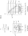
- Figs. 6 are diagrams each showing an example of functional blocks of the torque calculation unit 12 provided in the integrated control unit 1 shown in Fig. 1 .
- the torque calculation unit 12 is configured by using torque operation amount calculation units 26, and outputs the torque command value by adding a torque operation amount to the power command ⁇ m0 * in accordance with a map indicating the efficiency of the permanent magnet synchronous motor at the time of temperature change or a calculation formula for obtaining the efficiency.
- the map indicating the efficiency or the calculation formula for obtaining the efficiency is derived from measured values or magnetic field analysis, and is recorded in a storage device (not shown in the drawing) appropriately provided in the integrated control unit 1 or the torque calculation unit 12.
- the torque command values ⁇ m1 * and ⁇ m2 * are calculated by adding ⁇ m1 * and ⁇ m2 * to the power command ⁇ m0 *.
- the torque command values ⁇ m1 *, ⁇ m2 *, ⁇ m3 *, and ⁇ m4 * are calculated by adding ⁇ m1 *, ⁇ m2 *, ⁇ m3 *, and ⁇ m4 * to the power command ⁇ m0 *.
- the torque operation amount calculation units 26 discriminate the permanent magnet synchronous motor with high efficiency based on each of the temperature estimated values of the permanent magnet synchronous motors, and determines the torque operation amount from the discrimination result.
- the calculation of the operation amounts of the torque command values ⁇ m1 * to ⁇ m4 * shown in Figs. 6 and the compensation method thereof are merely examples, and if the configuration is such that each of the torque operation amounts is adjusted in accordance with the speed and the frequency in consideration of the temperature dependency of the dynamo-electric machine, the present invention is not limited that shown in Fig. 6 .
- the magnetic flux does not decrease when the temperature rises. Therefore, the iron loss (magnetic loss excluding the secondary copper loss generated in the rotor) becomes approximately constant regardless of the temperature.
- the total efficiency of the drive system can be improved by simply increasing the distribution of the torque commands to the dynamo-electric machine (induction motor) with a low temperature.
- Fig. 7 is a diagram for showing an outline configuration of a part of a railroad vehicle on which the drive device for the permanent magnet synchronous motor according to the present invention is mounted.
- a plurality of permanent magnet synchronous motors 4a, 4b, 4c, and 4d driven by an inverter 30 is coupled to axles of the railroad vehicle via reduction gears (not shown in the drawing).
- the railroad vehicle travels by tangential force generated between wheels 27 connected to the axles and rails 28.
- the temperature varies depending on each dynamo-electric machine because control of changing the distribution of torque for each shaft with respect to the travel direction is used due to a change in the center of gravity according to the travel direction, because of the influence of the way the traveling wind blows against the dynamo-electric machine, and because of the influence of the state of defacement of a ventilation duct of the dynamo-electric machine. Therefore, by applying the present invention to a railroad vehicle, it is possible to obtain an effect of improving the efficiency of the drive system of the railroad vehicle.
- the first embodiment it is possible to improve the total efficiency of a plurality of permanent magnet synchronous motors by individually changing the torque operation amount in consideration of the temperature dependency of each permanent magnet synchronous motor.
- a second embodiment is different from the first embodiment in that an estimated magnet temperature at the time of zero-torque control during driving under sensorless control is used as the temperature information of the permanent magnet synchronous motor. Accordingly, the temperature sensors shown in Fig. 2 are not necessary, and the temperature of the permanent magnet can be robustly estimated against the constant error of the inductance and resistance of the permanent magnet synchronous motor.
- Fig. 8 is a diagram for showing an example of functional blocks of a drive device for a permanent magnet synchronous motor according to a second embodiment.
- the sub control unit 2a of the second embodiment includes a PWM control unit 7a, a coordinate converter 8a, a vector control unit 9a, a current command calculation unit 10a, a temperature estimation unit 11a, and a speed estimation unit 31a.
- the current command calculation unit 10a outputs current command values I d1 * and I q1 * based on a torque command value ⁇ m1 * from the integrated control unit 1.
- the coordinate converter 8a converts three-phase currents I u1 , I v1 , and I w1 of a permanent magnet synchronous motor 3 detected by the current detector 5a into dq coordinates of the rotating coordinate system by using a phase angle ⁇ 1 , and outputs the same to the vector control unit 9a as I d1 and I q1 .
- the vector control unit 9a outputs voltage command values V d1 * and V q1 * so as to converge the current deviation to 0 by PI (Proportional-Integral) control or the like so that a d-axis current detection value I d1 and a q-axis current detection value I q1 match I d1 * and I q1 *, respectively.
- PI Proportional-Integral
- the PWM control unit 7a outputs a switching command SW 1 for controlling the voltage generation device 3a based on the voltage command values V d1 * and V q1 *.
- the speed estimation unit 31a estimates the angular frequency ⁇ 1 * of the rotor based on the current detection values I d1 and I q1 and the voltage command values V d1 * and V q1 *.
- the temperature estimation unit 11a outputs a magnet temperature estimated value T 1 ⁇ or a magnet magnetic flux estimated value K e1 ⁇ based on the current command values I d1 * and I q1 * or the current detection values I d1 and I q1 , the voltage command values V d1 * and V q1 *, and the angular frequency ⁇ 1 *.
- the magnet temperature and the magnet magnetic flux are calculated at a rate of -0.1%/°C with respect to a reference value, and either of them may be output as an estimated value.
- the magnet magnetic flux estimated value K e1 ⁇ will be used in the following description.
- the voltage command values v d * and v q * of the voltage generation device 3 may be referred to for the voltages v d and v q , and the current detection values i d and i q may be used for the currents.
- a resistance r 1 and inductances L d and L q depend on the winding temperature of the permanent magnet synchronous motor, the magnetic saturation characteristics of a magnetic material used for the iron core, the motor structure, and the current conditions, it is difficult to accurately grasp them.
- the inventors have found that the magnet magnetic flux K e can be estimated without being affected by the constant errors of the resistance r 1 and the inductances L d and L q by using the voltage command value V q * and the angular frequency ⁇ 1 * in a controlstabilized state in a state where the torque shown in Equation (2) is controlled to be 0 while intentionally setting the current command values I d1 * and I q1 * of the d-axis and the q-axis to 0.
- Equations (2) and (3) when the current command values I d * and I q * are set to 0 and the error of the current control by the vector control unit 10 is regarded as 0, the voltage command values V d * and V q * in a settled state are represented by the following equations (6) and (7).
- Equation (7) does not include the terms of the resistance r 1 and the inductances L d and L q , and the voltage command value V q * can be calculated only by ⁇ 1 * and K e .
- the drive control is performed by setting the current command values I d * and I q * to 0, and the q-axis voltage command value V q * and the angular frequency command value ⁇ 1 * in a state where the control is settled are used.
- a filtering process, a moving average process, or an integration process may be performed.
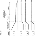
- the estimation of the magnet magnetic flux to be executed in the zero-torque control period is executed by using the zero-torque control period before the torque rising when the permanent magnet synchronous motor is restarted from the gate off and the free-run (coasting) of the rotor, or by using the zero-torque control period immediately before the gate off after the torque falling.
- Fig. 9 is a diagram for showing a time flow in which the magnet magnetic flux is estimated during a zero-torque control period before the torque rising at the time of coasting restart.
- Fig. 10 is a diagram for showing a time flow in which the magnet magnetic flux is estimated during the zero-torque control period immediately before the gate off after the torque falling.
- the current need not be exactly 0, and a minute d-axis current may flow.
- the voltage generation devices 3a and 3b since a period in which upper and lower output elements are simultaneously turned off is provided in order to prevent short-circuit of elements such as IGBTs included in upper and lower arms provided in each phase, the output voltage during the simultaneous turning-off period becomes insufficient when voltage compensation is not applied. Therefore, a well-known dead time compensation technique is used to compensate the voltage command value so as to output the voltage in accordance with the command value based on the polarity of the current detection value or the current command value.
- both of the d-axis current command value I d * and the q-axis current command value I q * shown in the first embodiment are set to 0 in the low speed region, if the polarity of the current detection value or the current command value used for the dead time compensation cannot be accurately grasped and the voltage is compensated based on the incorrect polarity as described above, the voltage error is adversely increased by the dead time compensation, and there is a possibility of deteriorating the estimation accuracy.
- a minute value is intentionally given to the d-axis current command value while setting the q-axis current command value to 0, so that the polarity of the current command value or the current detection value can be determined. Accordingly, even at the time of the zero-torque command, the polarity of the current can be discriminated, the dead time compensation can be accurately operated, and the voltage output accuracy can be improved.
- the magnitude of the minute current command value I d is set so that the magnetic flux (product of L d and I d ) due to the armature reaction is about 1/5 or less of the magnet magnetic flux K e so as not to be affected by the constant error of the d-axis inductance L d .
- the magnitude of the minute current command value I d * may be set in the range of Equation (11) with respect to the set value (reference value) K e * of the power generation constant and the d-axis inductance L d * set in the controller.
- temperature information can be obtained with high accuracy without using a temperature sensor by calculating the magnet temperature (or the magnet magnetic flux) in a period in which the torque command value in the sensorless control is controlled to 0.
- the second embodiment can accurately distribute the allocation of the torque operation amount described in the first embodiment, and can further improve the efficiency and simplify the system as compared to the first embodiment.
Landscapes
- Engineering & Computer Science (AREA)
- Power Engineering (AREA)
- Transportation (AREA)
- Mechanical Engineering (AREA)
- Life Sciences & Earth Sciences (AREA)
- Sustainable Development (AREA)
- Sustainable Energy (AREA)
- Control Of Ac Motors In General (AREA)
- Electric Propulsion And Braking For Vehicles (AREA)
- Control Of Multiple Motors (AREA)
Abstract
Description
- The present invention relates to a drive device for a dynamo-electric machine, and is particularly suitable as a drive device of a permanent magnet synchronous motor for a railroad vehicle.
- In recent years, railroad vehicles with high energy efficiency capable of large-scale transportation are attracting attention. More energy saving and improvement in efficiency are expected for railroad vehicles by introduction of a highly-efficient dynamo-electric machine, energy saving operation control, and control in accordance with the characteristics of the dynamo-electric machine.
- As one of these types of techniques, a technique for improving the efficiency and reliability of a drive system for a railroad vehicle by individually controlling a plurality of dynamo-electric machines because the railroad vehicle obtains power by the plurality of dynamo-electric machines is being studied.
- In order to improve the efficiency of a railroad vehicle, Patient
Literature 1 proposes a control device for a railroad vehicle which has a configuration in which an AC circuit breaker is provided between a power conversion device and each of a plurality of dynamo-electric machines and a circuit breaker control unit for individually controlling the opening and closing of the AC circuit breaker based on an operation control command from a cab is provided and which is driven under operating conditions where the dynamo-electric machine is highly efficient by reducing the number of dynamo-electric machines to be driven in accordance with torque necessary for the vehicle. - In order to maintain the output torque of an electric vehicle even in an open operation, Patient Literature 2 proposes an electric vehicle control device in which when the temperature of a dynamo-electric machine exceeds or is determined to exceed a preset allowance value, in order to change into a torque command suppressing the temperature of the dynamo-electric machine within the allowance value, a dynamo-electric machine whose torque is supplemented is selected in the order in which the temperature has a margin among the other dynamo-electric machines, and the shortage of the output torque in the dynamo-electric machine where the temperature rises is compensated.
-
- [Patent Literature 1]
Japanese Unexamined Patent Application Publication No. 2018-57185 - [Patent Literature 2]
Japanese Patent No. 5060266 - As a result of intensive studies for the purpose of further improving the efficiency of a drive device for a railroad vehicle, the inventors of the application have obtained the following findings.
- 1)
Patent Literature 1 discloses a technique for improving efficiency by driving a dynamo-electric machine at a point where the efficiency of the dynamo-electric machine is enhanced while switching the number of dynamo-electric machines using a circuit breaker. Then, although the dynamo-electric machine is selectively driven so that the temperature of the dynamo-electric machine to be driven is not biased against the temperature fluctuation of the dynamo-electric machine, only by operating the dynamo-electric machine with a low temperature to equalize the losses of a plurality of dynamo-electric machines, the losses themselves generated in the plurality of dynamo-electric machines are not reduced, and there is room for improvement to realize high efficiency. - In addition, if the technique described in
Patent Literature 1 is applied to a permanent magnet synchronous motor, since a rotor is provided with a permanent magnet, an iron loss occurs during the free-run of the rotor when an AC circuit breaker is opened, and there is a problem that the temperature of the permanent magnet synchronous motor rises. In particular, in a high speed region, although the magnetic flux is weakened by weaker field control during the normal control period, the magnetic flux is not weakened during the free-run at the time of opening, and thus the iron loss increases. In the vicinity of the highest speed, heat generation possibly increases in the open period rather than in the normal control period, and there is a problem in terms of cooling performance and reliability. - 2) In order to maintain the output torque of a vehicle even in an open operation,
Patent Literature 2 discloses a technique in which when the temperature of a dynamo-electric machine exceeds or is determined to exceed a preset allowance value, a dynamo-electric machine is selected in the order in which the temperature has a margin, and torque is supplemented. Although the effect of high efficiency cannot be obtained at the time of normal operation because of being operated only when the temperature is exceeded, if the technique ofPatent Literature 2 is applied and the torque of the dynamo-electric machine is allocated in the order in which the temperature has a margin, the resistance value becomes smaller and the effect of high efficiency can be obtained as the temperature decreases due to operating conditions where a copper loss is dominant among the losses of the dynamo-electric machine at the time of low-speed rotation and high torque. - However, there is a problem that the magnet magnetic flux increases and the efficiency is deteriorated as the temperature decreases due to operating conditions where an iron loss is dominant at the time of high-speed rotation and low torque In other words, it is not sufficient to realize high efficiency only by allocating the torque of the dynamo-electric machine in the order in which the temperature has a margin based on the temperature of the permanent magnet synchronous motor, and there is a possibility that the efficiency is deteriorated depending on operating conditions.
- 3) For the reasons described above, there is room for improvement to realize the high efficiency of a drive system using a plurality of dynamo-electric machines, in particular, permanent magnet synchronous motors.
- An object of the present invention is to improve the efficiency of a system for obtaining, when driving and controlling a plurality of dynamo-electric machines, power by the plurality of dynamo-electric machines by individually changing a torque operation amount in consideration of the temperature dependency of the dynamo-electric machines. Solution to Problem
- The present invention is provided with a plurality of voltage generation devices for outputting arbitrary voltages to a plurality of dynamo-electric machines and a control device for adjusting the output voltages of the voltage generation devices, and the control device acquires temperature information of each of the plurality of dynamo-electric machines, selects a relatively highly-efficient dynamo-electric machine from among the plurality of dynamo-electric machines based on each temperature information, and increases a torque command value for the selected dynamo-electric machine relative to the plurality of other dynamo-electric machines.
- According to the present invention, in a system driven by using a plurality of dynamo-electric machines, the high efficiency of the drive system can be realized and power consumption can be further reduced by individually changing the output torque of the plurality of dynamo-electric machines in consideration of the temperature dependency of the efficiency of the dynamo-electric machines.
-
-
Fig. 1 is a diagram for showing an example of functional blocks of a drive device for a permanent magnet synchronous motor according to a first embodiment. -
Fig. 2 is a diagram for showing an example in which a temperature detector is installed in the permanent magnet synchronous motor as a modified example of the drive device for the permanent magnet synchronous motor according to the first embodiment. -
Figs. 3 are diagrams each showing changes in the ratio of a copper loss to an iron loss when the permanent magnet synchronous motors are driven at the same rotational speed and the torque and the temperature are changed. -
Figs. 4 are diagrams each showing changes in the ratio of the copper loss to the iron loss when the permanent magnet synchronous motors are driven with the same torque and the rotational speed and the temperature are changed. -
Fig. 5 is a diagram for showing an example of an operation region where the permanent magnet synchronous motor becomes highly efficient when the temperature of the permanent magnet synchronous motor is higher or lower than a reference value. -
Figs. 6 are diagrams each showing an example of functional blocks of a torque calculation unit provided in an integrated control unit shown inFig. 1 . -
Fig. 7 is a diagram for showing an outline configuration of a part of a railroad vehicle on which the drive device for the permanent magnet synchronous motor according to the present invention is mounted. -
Fig. 8 is a diagram for showing an example of functional blocks of a drive device for a permanent magnet synchronous motor according to a second embodiment. -
Fig. 9 is a diagram for showing a time flow in which the magnet magnetic flux is estimated during a zero-torque control period before the torque rising at the time of coasting restart. -
Fig. 10 is a diagram for showing a time flow in which the magnet magnetic flux is estimated during the zero-torque control period immediately before the gate off after the torque falling. - Hereinafter, as forms of carrying out the present invention, first and second embodiments will be described in detail in accordance with the drawings. In each embodiment, requirements having the same reference numerals are shown as the same requirements or requirements having similar functions.
- Note that configurations described below are merely presented as embodiments, and implementation modes according to the present invention are not limited to the following embodiments.
-
Fig. 1 is a diagram for showing an example of functional blocks of a drive device for a permanent magnet synchronous motor according to a first embodiment. A configuration for adjusting a torque command value is shown as functional blocks so that the total efficiency of a drive system configured using plural permanent magnet synchronous motors is enhanced based on temperature information of each permanent magnet synchronous motor. - Although two permanent magnet
synchronous motors Fig. 1 , the number of permanent magnet synchronous motors is not limited to two as long as plural motors are used. Hereinafter, components and functions related to two motors are distinguished by using subscripts a and b so as to correspond to two motors. - In addition, in
Fig. 1 , electric power is transferred to and from anoverhead wire 25 via apantograph 24, and a current between the overhead wire side and the permanent magnet synchronous motor side can be cut off by a high-speed circuit breaker 23 and aline breaker 22. In addition, an LC filter circuit for smoothing a DC current that is configured using afilter reactor 21 and afilter capacitor 20 is provided betweenvoltage generation devices overhead wire 25. - A control device for drive control of the permanent magnet synchronous motors includes an integrated
control unit 1 andsub control units sub control units voltage generation devices synchronous motors - A
torque calculation unit 12 included in the integratedcontrol unit 1 outputs torque command values τm1* and τm2* to be generated in the permanent magnetsynchronous motors sub control units - Control programs for driving and controlling the permanent magnet
synchronous motors sub control units sub control units synchronous motors voltage generation devices - Here,
Fig. 1 shows only the minimum functional blocks necessary for the first embodiment, and a power converter configured using power devices such as a driving transistor such as an IGBT (Insulated Gate Bipora Transistor) and a diode and a control configuration for the power converter are shown using the block diagrams of thevoltage generation devices - The permanent magnet
synchronous motors -
Current detectors synchronous motors current detectors - In addition,
AC contactors voltage generation devices synchronous motors AC contactors control unit 1 or thesub control units - The
sub control units synchronous motors current detectors control unit 1. - In addition, as a modified example of the first embodiment,
Fig. 2 shows a configuration in whichtemperature detectors synchronous motors - Hereinafter, the relationship between the temperature and efficiency of the permanent magnet synchronous motor that is the main point of the present invention will be described.
- Losses generated in the permanent magnet synchronous motor can be largely classified into a copper loss, a mechanical loss, and an iron loss. When it is assumed for the permanent magnet synchronous motor that the input electric power is Pin, the output electric power is Pout, the torque is τm, the copper loss is Ws, the iron loss is Wi, the mechanical loss is Wm, and the angular frequency of the mechanical angle of the dynamo-electric machine is ωm, the efficiency n of the permanent magnet synchronous motor is represented by Equation (1) .
[Equation 1]
- In addition, the torque τm of the permanent magnet synchronous motor is represented by Equation (2).
[Equation 2]
- Here, m is the number of phases, Pm is the number of pole pairs, Ke is a magnet magnetic flux (power generation constant), Id is a d-axis current, Iq is a q-axis current, Ld is a d-axis inductance, and Lq is a q-axis inductance.
- The first term in Equation (2) is the above-described magnet torque (torque generated by attraction and repulsion between the magnetic pole of the rotational magnetic field and the magnetic pole of the permanent magnet of the rotor), and the second term in Equation (2) is the above-described reluctance torque (torque generated by attraction force between the magnetic pole of the rotational magnetic field of the stator and the magnetic salient pole of the rotor).
- It is well known that since the magnet torque is determined by the product of the magnet magnetic flux Ke and the q-axis current Iq, the magnet torque fluctuates due to the influence of the fluctuation of the magnet magnetic flux Ke, and the output torque increases or decreases. For example, a demagnetization of -0.1%/°C of the permanent magnet means that when the temperature rises by 10°C, the magnet magnetic flux Ke decreases by 1%. That is, it is often considered that the lowtemperature condition in which the magnet magnetic flux increases results in a more highly efficient operation because the output torque of molecules in Equation (1) increases.
- In order to improve the efficiency of the drive system based on such an idea, for example, it is conceivable to supplement torque in the order in which the temperature of the dynamo-electric machine has a margin by applying the technique described in
Patent Literature 2 for realizing high efficiency. - However, the inventors focused on the temperature dependency of the loss indicated by the denominator of Equation (1) based on detailed study, and found that the permanent magnet synchronous motor with a low temperature does not simply becomes high efficiency, but becomes high efficiency in different operation regions at low and high temperatures depending on the operating conditions of torque and frequency.
- Hereinafter, outlines of the copper loss Ws, the mechanical loss Wm, and the iron loss Wi and the temperature dependency thereof will be described.
- The copper loss Ws is a loss generated in a stator winding, and can be calculated from the current value flowing in the permanent magnet synchronous motor and the resistance value. Regarding the temperature dependency of the copper loss Ws, since the resistance value is changed in accordance with the temperature coefficient of a material used for the stator winding, the resistance value increases and the copper loss Ws tends to increase as the temperature rises.
- The mechanical loss Wm is generated by a pressure loss due to a cooling fan provided in the rotor, friction of a bearing supporting the rotor at a frame of the permanent magnet synchronous motor, or the like, and can be generally calculated as a function of a drive frequency. Regarding the temperature dependency of the mechanical loss Wm, strictly speaking, although there is a change in the viscosity of grease used for a bearing, the change can be ignored in the dynamo-electric machine for railroad vehicles. Therefore, the mechanical loss Wm of the dynamo-electric machine for railroad vehicles is often treated as not being affected by temperature.
- The iron loss Wi is a magnetic loss corresponding to the area of a hysteresis loop when the magnetic flux in a magnetic material used for a stator core or a rotor core is changed by applying an AC magnetic field, and is defined as the sum of a hysteresis loss and an eddy current loss and can be generally calculated as a function of magnetic flux density and a frequency. Regarding the temperature dependency of the iron loss Wi, the magnet magnetic flux itself largely affecting the iron loss in the permanent magnet synchronous motor has temperature dependency, and demagnetizes at, for example, about -0.1%/°C when the temperature rises as described above.
- Further, the hysteresis loss in the iron loss Wi is often considered to have substantially no temperature dependency. However, when the electric resistance of the iron core increases due to the temperature rise, the eddy current loss tends to decrease. Therefore, the iron loss Wi in the permanent magnet synchronous motor tends to decrease as the temperature becomes higher.
- As described above, in terms of the loss in the permanent magnet synchronous motor, when the temperature is low, the copper loss decreases and the iron loss increases, whereas when the temperature is high, the copper loss increases and the iron loss decreases. That is, since the copper loss and the iron loss have a trade-off relationship with respect to the temperature, when considering a change in the loss at the time of temperature change under certain operating conditions, the loss as a dynamo-electric machine differently decreases under low or high temperature conditions depending on the ratio of the iron loss to the copper loss.
-
Figs. 3 are diagrams each showing the change characteristics of the ratio of the copper loss to the iron loss when the permanent magnet synchronous motors are driven at the same rotational speed and the torque and the temperature are changed. -
Figs. 3(a), 3(b), and 3(c) show calculation results by magnetic field analysis at the time of high torque, at the time of middle torque, and at the time of low torque, respectively, and the current value is adjusted so that the output torque becomes the same even when the temperature is changed. In addition, the values in each drawing are normalized by the loss under the temperature condition where the total of the copper loss and the iron loss is maximized under each condition. Note that the resistance and the magnet temperature are assumed to be similarly changed. - At the time of high torque, as shown in
Fig. 3(a) , a large current flows under the operating condition of large torque, and thus the ratio of the copper loss becomes large with respect toFigs. 3(b) and 3(c) . In addition, when the temperature rises, an increase in the copper loss becomes larger than a decrease in the iron loss, and when the temperature of the permanent magnet synchronous motor becomes lower, the efficiency becomes higher. - The condition at the time of middle torque is, as shown in
Fig. 3(b) , a condition where the load torque becomes smaller and the current becomes smaller than those inFig. 3(a) , and thus when the temperature of the dynamo-electric machine is higher, the efficiency becomes slightly higher. - The condition at the time of low torque an operating condition where the torque is substantially 0, and under such a condition, as shown in
Fig. 3(c) , the total of the copper loss and the iron loss can be reduced by nearly 30% when the temperature is high as compared to when the temperature is low. - That is, under the operating condition where the load torque is small, among the plurality of permanent magnet synchronous motors, the torque command value of the permanent magnet synchronous motor with a high temperature is intentionally increased, whereas the torque command value of the permanent magnet synchronous motor with a low temperature is decreased, so that it can be understood that the permanent magnet synchronous motors can be driven with high efficiency as a whole.
-
Figs. 4 are diagrams each showing the change characteristics of the ratio of the copper loss to the iron loss when the permanent magnet synchronous motors are driven with the same torque and the rotational speed and the temperature are changed. -
Figs. 4(a), 4(b), and 4(c) show calculation results by magnetic field analysis in a low-speed range, in a medium-speed range, and in a high-speed range, respectively, and the current is adjusted so that the output torque becomes the same even when the temperature is changed. In addition, the values in each drawing are normalized by the loss under the temperature condition where the total of the copper loss and the iron loss is maximized under each condition. Note that the resistance and the magnet temperature are assumed to be similarly changed. - In the low-speed range, as shown in
Fig. 4(a) , the iron loss is small and the ratio of the copper loss accordingly becomes relatively higher in the operating condition where the rotational speed is low. In addition, when the temperature rises, an increase in the copper loss becomes larger than a decrease in the iron loss, and when the temperature of the permanent magnet synchronous motor becomes lower, the efficiency becomes higher. - The condition in the medium-speed range is, as shown in
Fig. 4(b) , is a condition where the rotational speed is higher and the ratio of the iron loss becomes relatively larger than those inFig. 4(a) , and thus is a region where the efficiency is not substantially changed even when the temperature of the dynamo-electric machine is changed. - In the high-speed range, the rotational speed is higher than that in
Fig. 4(b) , and under such a condition, as shown inFig. 4(c) , the total of the copper loss and the iron loss can be reduced by nearly 10% when the temperature is high as compared to when the temperature is low. - That is, under the condition where the rotational speed is high, among the plurality of permanent magnet synchronous motors, the torque command value of the permanent magnet synchronous motor with a high temperature is intentionally increased, whereas the torque command value of the permanent magnet synchronous motor with a low temperature is decreased, so that it can be understood that the permanent magnet synchronous motors can be driven with high efficiency as a whole.
-
Fig. 5 is a diagram for showing an example of an operation region where the permanent magnet synchronous motor becomes highly efficient when the temperature of the permanent magnet synchronous motor is higher or lower than a reference value with respect to the speed (horizontal axis) and the torque (vertical axis). - As shown in
Figs. 3 andFigs. 4 , when the median value of the specification range of temperatures is used as a reference, the region of high efficiency due to temperatures has a boundary with respect to the torque and the speed. In other words, when power is obtained by using at least two or more permanent magnet synchronous motors, the high efficiency of the system can be realized by changing the distribution of the torque command values so as to maximize the total efficiency in accordance with the temperature, speed, and torque. - Here,
Figs. 6 are diagrams each showing an example of functional blocks of thetorque calculation unit 12 provided in theintegrated control unit 1 shown inFig. 1 . - Specifically, the torque command values τm1* and τm2* shown in
Fig. 1 will be described usingFigs. 6 . As shown inFigs. 6(b) and 6(c) , thetorque calculation unit 12 is configured by using torque operationamount calculation units 26, and outputs the torque command value by adding a torque operation amount to the power command τm0* in accordance with a map indicating the efficiency of the permanent magnet synchronous motor at the time of temperature change or a calculation formula for obtaining the efficiency. The map indicating the efficiency or the calculation formula for obtaining the efficiency is derived from measured values or magnetic field analysis, and is recorded in a storage device (not shown in the drawing) appropriately provided in theintegrated control unit 1 or thetorque calculation unit 12. - For example, when being applied to two motor units, as shown in (b), the torque command values τm1* and τm2* are calculated by adding Δτm1* and Δτm2* to the power command τm0*.
- In addition, when being applied to four motor units, as shown in (c), the torque command values τm1*, τm2*, τm3*, and τm4* are calculated by adding Δτm1*, Δτm2*, Δτm3*, and Δτm4* to the power command τm0*.
- The torque operation
amount calculation units 26 discriminate the permanent magnet synchronous motor with high efficiency based on each of the temperature estimated values of the permanent magnet synchronous motors, and determines the torque operation amount from the discrimination result. However, in order not to change the total amount of torque output from the drive system with respect to the conventional configuration shown inFig. 6 (a) , as shown inFig. 6 (b) or 6(c), the sum of torque compensation amounts is adjusted so as to be approximately 0 (Δτm1*+Δτm2*=0 or Δτm1*+Δτm2*+Δτm3*+Δτm4*=0), in other words, the total amount of the torque command values in the drive system is adjusted so as to be approximately constant. - Here, the calculation of the operation amounts of the torque command values Δτm1* to Δτm4* shown in
Figs. 6 and the compensation method thereof are merely examples, and if the configuration is such that each of the torque operation amounts is adjusted in accordance with the speed and the frequency in consideration of the temperature dependency of the dynamo-electric machine, the present invention is not limited that shown inFig. 6 . - In addition, although the example of operating the torque command values is shown in the first embodiment, a configuration of operating the current command values or the voltage command values corresponding to the torque command values may be employed.
- However, there is a concern that the temperature rises by actively using the dynamo-electric machine with a high temperature at the time of low torque or in the high-speed range. However, since a railroad vehicle does not continue a normal operation at the same frequency or the torque operating point and repeats stop, acceleration, deceleration, and stop operations, only the dynamo-electric machine with a high temperature is not unevenly driven, and thus abnormal heat generation or the like does not occur. However, when it is predicted that the temperature exceeds a temperature allowance value considering the irreversible demagnetization of the permanent magnet, a limiter for temperature is provided to stop the compensation without increasing the torque command value of the dynamo-electric machine with a high temperature.
- On the other hand, in the case of the drive system using an induction motor as the dynamo-electric machine, since no permanent magnet is used as the dynamo-electric machine, the magnetic flux does not decrease when the temperature rises. Therefore, the iron loss (magnetic loss excluding the secondary copper loss generated in the rotor) becomes approximately constant regardless of the temperature. In other words, in the case of the induction motor, the total efficiency of the drive system can be improved by simply increasing the distribution of the torque commands to the dynamo-electric machine (induction motor) with a low temperature.
-
Fig. 7 is a diagram for showing an outline configuration of a part of a railroad vehicle on which the drive device for the permanent magnet synchronous motor according to the present invention is mounted. A plurality of permanentmagnet synchronous motors inverter 30 is coupled to axles of the railroad vehicle via reduction gears (not shown in the drawing). The railroad vehicle travels by tangential force generated betweenwheels 27 connected to the axles and rails 28. - In the railroad vehicle, the temperature varies depending on each dynamo-electric machine because control of changing the distribution of torque for each shaft with respect to the travel direction is used due to a change in the center of gravity according to the travel direction, because of the influence of the way the traveling wind blows against the dynamo-electric machine, and because of the influence of the state of defacement of a ventilation duct of the dynamo-electric machine. Therefore, by applying the present invention to a railroad vehicle, it is possible to obtain an effect of improving the efficiency of the drive system of the railroad vehicle.
- As described above, in the first embodiment, it is possible to improve the total efficiency of a plurality of permanent magnet synchronous motors by individually changing the torque operation amount in consideration of the temperature dependency of each permanent magnet synchronous motor.
- A second embodiment is different from the first embodiment in that an estimated magnet temperature at the time of zero-torque control during driving under sensorless control is used as the temperature information of the permanent magnet synchronous motor. Accordingly, the temperature sensors shown in
Fig. 2 are not necessary, and the temperature of the permanent magnet can be robustly estimated against the constant error of the inductance and resistance of the permanent magnet synchronous motor. -
Fig. 8 is a diagram for showing an example of functional blocks of a drive device for a permanent magnet synchronous motor according to a second embodiment. - The
sub control unit 2a of the second embodiment includes aPWM control unit 7a, a coordinateconverter 8a, avector control unit 9a, a currentcommand calculation unit 10a, atemperature estimation unit 11a, and aspeed estimation unit 31a. - The current
command calculation unit 10a outputs current command values Id1* and Iq1* based on a torque command value τm1* from theintegrated control unit 1. - The coordinate
converter 8a converts three-phase currents Iu1, Iv1, and Iw1 of a permanent magnet synchronous motor 3 detected by thecurrent detector 5a into dq coordinates of the rotating coordinate system by using a phase angle θ1, and outputs the same to thevector control unit 9a as Id1 and Iq1. - The
vector control unit 9a outputs voltage command values Vd1* and Vq1* so as to converge the current deviation to 0 by PI (Proportional-Integral) control or the like so that a d-axis current detection value Id1 and a q-axis current detection value Iq1 match Id1* and Iq1*, respectively. - The
PWM control unit 7a outputs a switching command SW1 for controlling thevoltage generation device 3a based on the voltage command values Vd1* and Vq1*. - The
speed estimation unit 31a estimates the angular frequency ω1* of the rotor based on the current detection values Id1 and Iq1 and the voltage command values Vd1* and Vq1*. - The
temperature estimation unit 11a outputs a magnet temperature estimated value T1^ or a magnet magnetic flux estimated value Ke1^ based on the current command values Id1* and Iq1* or the current detection values Id1 and Iq1, the voltage command values Vd1* and Vq1*, and the angular frequency ω1*. The magnet temperature and the magnet magnetic flux are calculated at a rate of -0.1%/°C with respect to a reference value, and either of them may be output as an estimated value. The magnet magnetic flux estimated value Ke1^ will be used in the following description. - In addition, since the block diagram inside the
sub control unit 2b has the same configuration as that of thesub control unit 2a, the illustration thereof is omitted. - Hereinafter, the principle of estimating the temperature of the permanent magnet with high accuracy will be described. The voltage equations of the permanent magnet synchronous motor are represented by the following equations (3) and (4).
[Equation 3]
[Equation 4]
- If it is assumed that the state quantities of the actual voltage, current, resistance value, and inductance of the permanent magnet synchronous motor can be accurately grasped, the estimated value Ke^ of the magnetic flux can be calculated by Equation (5).
[Equation 5]
- Considering the calculation of the constant Ke^ of the magnet magnetic flux in accordance with Equation (5), the voltage command values vd* and vq* of the voltage generation device 3 may be referred to for the voltages vd and vq, and the current detection values id and iq may be used for the currents. However, since a resistance r1 and inductances Ld and Lq depend on the winding temperature of the permanent magnet synchronous motor, the magnetic saturation characteristics of a magnetic material used for the iron core, the motor structure, and the current conditions, it is difficult to accurately grasp them.
- Thus, in order to estimate the magnet magnetic flux Ke without being affected by the constant error, the inventors have found that the magnet magnetic flux Ke can be estimated without being affected by the constant errors of the resistance r1 and the inductances Ld and Lq by using the voltage command value Vq* and the angular frequency ω1* in a controlstabilized state in a state where the torque shown in Equation (2) is controlled to be 0 while intentionally setting the current command values Id1* and Iq1* of the d-axis and the q-axis to 0.
- In Equations (2) and (3), when the current command values Id* and Iq* are set to 0 and the error of the current control by the vector control unit 10 is regarded as 0, the voltage command values Vd* and Vq* in a settled state are represented by the following equations (6) and (7).
[Equation 6]
[Equation 7]
- That is, the estimated value Ke^ of the magnet magnetic flux can be calculated by the following equation (8).
[Equation 8] - When the current command values Id* and Ip* are set to 0 and the error by the current control is 0, the voltage command value Vq* of the q-axis is put in a state of outputting a voltage to cancel an induced voltage by the actual magnet magnetic flux Ke. Accordingly, it can be understood that Equation (7) does not include the terms of the resistance r1 and the inductances Ld and Lq, and the voltage command value Vq* can be calculated only by ω1* and Ke.
- In addition, when a case in which the magnet magnetic flux fluctuates at the same frequency is exemplified, according to Equation (7), when the temperature of the permanent magnet rises and the actual magnet magnetic flux Ke decreases, Vq* in a settled state also decreases. On the other hand, when the temperature of the permanent magnet is lowered and the actual magnet magnetic flux Ke increases, Vq* in a settled state also increases. Thus, the magnet magnetic flux Ke can be estimated based on the q-axis voltage command value Vq* when the current command values Id* and Iq* are set to 0. However, according to Equation (8), the estimation method of the second embodiment cannot be applied in principle under the condition that the rotor speed ω1 of the permanent magnet synchronous motor is 0.
- Here, in the estimation method of the second embodiment, since it is necessary that the current deviation by the current control is 0, the drive control is performed by setting the current command values Id* and Iq* to 0, and the q-axis voltage command value Vq* and the angular frequency command value ω1* in a state where the control is settled are used. In addition, in order to eliminate the influence of noise, a filtering process, a moving average process, or an integration process may be performed.
- Next, the estimation of the magnet magnetic flux to be executed in the zero-torque control period is executed by using the zero-torque control period before the torque rising when the permanent magnet synchronous motor is restarted from the gate off and the free-run (coasting) of the rotor, or by using the zero-torque control period immediately before the gate off after the torque falling.
-
Fig. 9 is a diagram for showing a time flow in which the magnet magnetic flux is estimated during a zero-torque control period before the torque rising at the time of coasting restart. In addition,Fig. 10 is a diagram for showing a time flow in which the magnet magnetic flux is estimated during the zero-torque control period immediately before the gate off after the torque falling. - However, at the time of the zero-torque command, the current need not be exactly 0, and a minute d-axis current may flow. In the
voltage generation devices - In particular, in a low speed region where the induced voltage of the permanent magnet synchronous motor is low and the modulation rate is low, a number of voltage pulses having a narrow width are output, so that the ratio of the simultaneous turning-off period to the output voltage becomes relatively large, and the influence on the output voltage is likely to become large.
- That is, when both of the d-axis current command value Id* and the q-axis current command value Iq* shown in the first embodiment are set to 0 in the low speed region, if the polarity of the current detection value or the current command value used for the dead time compensation cannot be accurately grasped and the voltage is compensated based on the incorrect polarity as described above, the voltage error is adversely increased by the dead time compensation, and there is a possibility of deteriorating the estimation accuracy.
- In response to this, a minute value is intentionally given to the d-axis current command value while setting the q-axis current command value to 0, so that the polarity of the current command value or the current detection value can be determined. Accordingly, even at the time of the zero-torque command, the polarity of the current can be discriminated, the dead time compensation can be accurately operated, and the voltage output accuracy can be improved.
- However, as shown in Equation (10), the magnitude of the minute current command value Id is set so that the magnetic flux (product of Ld and Id) due to the armature reaction is about 1/5 or less of the magnet magnetic flux Ke so as not to be affected by the constant error of the d-axis inductance Ld. For example, in the case of 1/5 or less, the magnitude of the minute current command value Id* may be set in the range of Equation (11) with respect to the set value (reference value) Ke* of the power generation constant and the d-axis inductance Ld* set in the controller.
[Equation 9]
[Equation 10]
[Equation 11]
- As described above, in the second embodiment, temperature information can be obtained with high accuracy without using a temperature sensor by calculating the magnet temperature (or the magnet magnetic flux) in a period in which the torque command value in the sensorless control is controlled to 0. In addition, the second embodiment can accurately distribute the allocation of the torque operation amount described in the first embodiment, and can further improve the efficiency and simplify the system as compared to the first embodiment.
-
- 1
- ...integrated control unit
- 2
- ...sub control unit
- 3 ...
- voltage generation device
- 4 ...
- permanent magnet synchronous motor
- 5 ...
- current detector
- 6 ...
- AC contactor
- 7 ...
- PWM control unit
- 8 ...
- coordinate converter
- 9 ...
- vector control unit
- 10 ...
- current command calculation unit
- 11 ...
- magnet temperature estimation unit
- 12 ...
- torque command calculation unit
- 20 ...
- filter capacitor
- 21 ...
- filter reactor
- 22 ...
- line breaker
- 23 ...
- high-speed circuit breaker
- 24 ...
- pantograph
- 25 ...
- overhead wire
- 26 ...
- torque compensation calculation unit
- 27 ...
- wheel
- 28 ...
- rail
- 30 ...
- inverter
- 31 ...
- speed estimation calculation unit
- 40 ...
- temperature detector
Claims (19)
- A drive device for a dynamo-electric machine, comprising:a plurality of voltage generation devices for outputting arbitrary voltages to a plurality of dynamo-electric machines; anda control device for adjusting the output voltages of the voltage generation devices,wherein the control device acquires the temperature of each of the plurality of dynamo-electric machines, selects a relatively highly-efficient dynamo-electric machine from among the plurality of dynamo-electric machines based on each temperature, and increases a torque command value for the selected dynamo-electric machine relative to the plurality of other dynamo-electric machines.
- The drive device for a dynamo-electric machine according to claim 1,
wherein the total amount of the torque command values for the plurality of dynamo-electric machines is approximately constant. - The drive device for a dynamo-electric machine according to claim 1 or 2,
wherein the dynamo-electric machines are permanent magnet synchronous motors. - The drive device for a dynamo-electric machine according to claim 3,
wherein, in a low speed region, the control device selects a motor with a relatively low temperature among the plurality of permanent magnet synchronous motors, and in a high speed region, the control device selects a motor with a relatively high temperature among the plurality of permanent magnet synchronous motors. - The drive device for a dynamo-electric machine according to claim 3,
wherein the control device selects a motor with a relatively low temperature among the plurality of permanent magnet synchronous motors when the torque command value is large, and selects a motor with a relatively high temperature among the plurality of permanent magnet synchronous motors when the torque command value is small. - The drive device for a dynamo-electric machine according to any one of claims 3 to 5,
wherein the control device records a map indicating the efficiency of each permanent magnet synchronous motor at the time of temperature changes of the permanent magnet synchronous motors or a calculation formula for obtaining the efficiency, and selects a relatively highly-efficient motor from among the plurality of permanent magnet synchronous motors against the temperature changes of the permanent magnet synchronous motors based on the map or the calculation formula. - The drive device for a dynamo-electric machine according to any one of claims 3 to 6,
wherein the control device does not increase the torque command value for the permanent magnet synchronous motor with a high temperature when the temperature exceeds a preset allowable temperature in a high speed region or a low torque region of the permanent magnet synchronous motor. - The drive device for a dynamo-electric machine according to any one of claims 3 to 7,
wherein the temperature estimated value of a permanent magnet in a rotor of the permanent magnet synchronous motor is used as the temperature. - The drive device for a dynamo-electric machine according to claim 8,
wherein the control device estimates the temperature or the amount of magnetic flux of the permanent magnet by using a period of driving while setting the torque command value for the permanent magnet synchronous motor to approximately 0. - The drive device for a dynamo-electric machine according to claim 9,
wherein when the direction of a magnetic pole formed by the permanent magnet in the rotor is a d-axis, the direction orthogonal to the d-axis by an electric angle is a q-axis, a set value of inductance in the d-axis and a set value of the magnet magnetic flux in the control device are Ld* and Ke*, respectively, and a current command value of the d-axis is id*, substantially 0 of the torque command value means that the current command value of the q-axis is 0 and the current command value id* of the d-axis is
- The drive device for a dynamo-electric machine according to claim 9 or 10,
wherein the control device estimates the temperature or the amount of magnetic flux during a period of setting the torque command value to 0 provided before rising the torque command value at the time of coasting restart from the time the voltage output to the permanent magnet synchronous motor is stopped and the free-run state of the rotor of the permanent magnet synchronous motor. - The drive device for a dynamo-electric machine according to any one of claims 9 to 11,
wherein when the rotor speed of the permanent magnet synchronous motor is a predetermined value or larger after the torque command value is narrowed down to 0, the control device estimates the temperature or the amount of magnetic flux in a period of driving while setting the torque command value to 0. - The drive device for a dynamo-electric machine according to claim 1 or 2,
wherein the dynamo-electric machine is an induction motor. - The drive device for a dynamo-electric machine according to claim 13,
wherein the control device increases the torque command value for the induction motor with a low temperature relative to other induction motors. - A railroad vehicle wherein the drive device for a dynamo-electric machine according to any one of claims 1 to 14 is mounted and the dynamo-electric machine is a motor for driving wheels.
- A method for driving a dynamo-electric machine, comprising:acquiring temperature information of each of a plurality of dynamo-electric machines driven by a plurality of voltage generation devices for outputting arbitrary voltages,selecting a relatively highly-efficient dynamo-electric machine from among the plurality of dynamo-electric machines based on each temperature information, andincreasing a torque command value for the selected dynamo-electric machine relative to the plurality of other dynamo-electric machines.
- The method for driving a dynamo-electric machine according to claim 16,
wherein the total amount of the torque command values for the plurality of dynamo-electric machines is approximately constant. - The method for driving a dynamo-electric machine according to claim 16 or 17,wherein the dynamo-electric machines are permanent magnet synchronous motors, andwherein, in a low speed region, a motor with a relatively small value of the temperature information is selected among the plurality of permanent magnet synchronous motors, and in a high speed region, a motor with a relatively large value of the temperature information is selected among the plurality of permanent magnet synchronous motors.
- The method for driving a dynamo-electric machine according to claim 16 or 17,wherein the dynamo-electric machines are permanent magnet synchronous motors, andwherein a motor with a relatively small value of the temperature information is selected among the plurality of permanent magnet synchronous motors when the torque command value is large, and a motor with a relatively large value of the temperature information is selected among the plurality of permanent magnet synchronous motors when the torque command value is small.
Applications Claiming Priority (2)
| Application Number | Priority Date | Filing Date | Title |
|---|---|---|---|
| JP2018247828 | 2018-12-28 | ||
| PCT/JP2019/044581 WO2020137219A1 (en) | 2018-12-28 | 2019-11-13 | Drive device for dynamo-electric machine, and method for driving |
Publications (3)
| Publication Number | Publication Date |
|---|---|
| EP3905511A1 true EP3905511A1 (en) | 2021-11-03 |
| EP3905511A4 EP3905511A4 (en) | 2022-10-05 |
| EP3905511B1 EP3905511B1 (en) | 2024-11-06 |
Family
ID=71126551
Family Applications (1)
| Application Number | Title | Priority Date | Filing Date |
|---|---|---|---|
| EP19906074.0A Active EP3905511B1 (en) | 2018-12-28 | 2019-11-13 | Drive device for dynamo-electric machine, and method for driving |
Country Status (4)
| Country | Link |
|---|---|
| EP (1) | EP3905511B1 (en) |
| JP (1) | JP7181946B2 (en) |
| CN (1) | CN113196642B (en) |
| WO (1) | WO2020137219A1 (en) |
Cited By (2)
| Publication number | Priority date | Publication date | Assignee | Title |
|---|---|---|---|---|
| EP4617100A1 (en) * | 2024-03-13 | 2025-09-17 | Christian Rudolph | Electric drive for a system for maintaining switch points |
| EP4704329A1 (en) * | 2024-09-03 | 2026-03-04 | Volvo Truck Corporation | System and method for controlling an electrical machine |
Families Citing this family (6)
| Publication number | Priority date | Publication date | Assignee | Title |
|---|---|---|---|---|
| US20240014765A1 (en) * | 2020-10-20 | 2024-01-11 | Fanuc Corporation | Parameter setting device for setting parameter of electric motor model |
| WO2022085545A1 (en) * | 2020-10-20 | 2022-04-28 | ファナック株式会社 | Temperature estimation device for estimating temperature of temperature detector of electric motor |
| CN113400953B (en) * | 2021-07-30 | 2024-03-26 | 精进电动科技股份有限公司 | Dual-motor torque distribution method and dual-motor system |
| DE102022208756A1 (en) * | 2022-08-24 | 2024-02-29 | Siemens Mobility GmbH | Electric drive system |
| JP2024061945A (en) * | 2022-10-24 | 2024-05-09 | 三菱電機株式会社 | Power Conversion Equipment |
| CN119636443B (en) * | 2025-02-18 | 2025-06-10 | 西安建筑科技大学 | Method and system for controlling torque optimization distribution of electric drive multi-axle vehicle |
Family Cites Families (20)
| Publication number | Priority date | Publication date | Assignee | Title |
|---|---|---|---|---|
| AU586358B2 (en) * | 1986-10-08 | 1989-07-06 | Hitachi Limited | A control apparatus for an induction motor |
| JPH0538182A (en) * | 1991-07-24 | 1993-02-12 | Hitachi Ltd | Elevator equipment |
| JPH0739018A (en) * | 1993-07-16 | 1995-02-07 | Nissan Motor Co Ltd | Power control device for electric vehicle |
| JPH07131994A (en) * | 1993-10-29 | 1995-05-19 | Nissan Motor Co Ltd | Drive controller for multiple motors |
| JPH1118496A (en) * | 1997-06-18 | 1999-01-22 | Hitachi Ltd | Electric vehicle control device and control method |
| JPH1169871A (en) * | 1997-08-14 | 1999-03-09 | Oki Electric Ind Co Ltd | Motor controlling device and automatic apparatus |
| JP4023249B2 (en) | 2002-07-25 | 2007-12-19 | ダイキン工業株式会社 | Compressor internal state estimation device and air conditioner |
| JP2006297506A (en) * | 2005-04-18 | 2006-11-02 | Amada Co Ltd | Tapping device for punch press and method for controlling tapping for punch press |
| JP5060266B2 (en) | 2007-12-14 | 2012-10-31 | 株式会社東芝 | Electric vehicle control device |
| JP5281370B2 (en) | 2008-11-25 | 2013-09-04 | トヨタ自動車株式会社 | AC motor control device |
| US7979171B2 (en) * | 2010-09-21 | 2011-07-12 | Ford Global Technologies, Llc | Permanent magnet temperature estimation |
| JP5420006B2 (en) * | 2012-03-22 | 2014-02-19 | 三菱電機株式会社 | Synchronous machine controller |
| JP2014024442A (en) * | 2012-07-26 | 2014-02-06 | Toyota Motor Corp | Control device for hybrid vehicle power device |
| JP2014068443A (en) * | 2012-09-25 | 2014-04-17 | Hitachi Automotive Systems Ltd | Drive controller for rotary electric machine and electric vehicle drive system |
| CN104718694B (en) | 2012-10-12 | 2017-05-10 | 三菱电机株式会社 | Synchronous machine control device |
| JP5652489B2 (en) | 2013-03-21 | 2015-01-14 | ダイキン工業株式会社 | Power control board for refrigeration equipment |
| JP2015035874A (en) | 2013-08-08 | 2015-02-19 | トヨタ自動車株式会社 | Power controller |
| JP6111291B2 (en) * | 2015-06-22 | 2017-04-05 | 株式会社神戸製鋼所 | Mobile crane |
| JP2018057185A (en) | 2016-09-29 | 2018-04-05 | 株式会社日立製作所 | Railway vehicular control device |
| JP2018137932A (en) | 2017-02-23 | 2018-08-30 | コニカミノルタ株式会社 | Motor control device, control method, and image forming apparatus |
-
2019
- 2019-11-13 WO PCT/JP2019/044581 patent/WO2020137219A1/en not_active Ceased
- 2019-11-13 CN CN201980083421.6A patent/CN113196642B/en active Active
- 2019-11-13 JP JP2020562907A patent/JP7181946B2/en active Active
- 2019-11-13 EP EP19906074.0A patent/EP3905511B1/en active Active
Cited By (2)
| Publication number | Priority date | Publication date | Assignee | Title |
|---|---|---|---|---|
| EP4617100A1 (en) * | 2024-03-13 | 2025-09-17 | Christian Rudolph | Electric drive for a system for maintaining switch points |
| EP4704329A1 (en) * | 2024-09-03 | 2026-03-04 | Volvo Truck Corporation | System and method for controlling an electrical machine |
Also Published As
| Publication number | Publication date |
|---|---|
| WO2020137219A1 (en) | 2020-07-02 |
| CN113196642B (en) | 2024-06-28 |
| CN113196642A (en) | 2021-07-30 |
| JP7181946B2 (en) | 2022-12-01 |
| EP3905511A4 (en) | 2022-10-05 |
| JPWO2020137219A1 (en) | 2021-10-21 |
| EP3905511B1 (en) | 2024-11-06 |
Similar Documents
| Publication | Publication Date | Title |
|---|---|---|
| EP3905511B1 (en) | Drive device for dynamo-electric machine, and method for driving | |
| EP2642658B1 (en) | Controller for electric motor | |
| US8278855B2 (en) | Controller of motor preventing an increase in inverter loss | |
| JP7312065B2 (en) | Motor control device, electromechanical integrated unit, generator system, motor drive device and electric vehicle system | |
| KR101199038B1 (en) | Power converter for driving motor | |
| EP2322374B1 (en) | Power conversion device | |
| CN102624314B (en) | Variable-flux motor drive system | |
| CN107005181B (en) | Motor drive control device | |
| CN101529714A (en) | Vector control device for permanent magnet synchronous motor | |
| CN103633920A (en) | Control apparatus for rotary electric machine, rotary electric machine drive system, and control method for rotary electric machine | |
| EP2804311B1 (en) | Inverter control device | |
| CN101490946A (en) | Variable flux motor drive system | |
| CN104718694A (en) | Synchronous machine control device | |
| EP2713502B1 (en) | AC motor drive system and motor vehicle | |
| EP3985862A1 (en) | Device and method for driving permanent magnet synchronous motor, and railway vehicle | |
| EP4123898A1 (en) | Synchronous machine control device, synchronous machine control method, and electric vehicle | |
| JP6203036B2 (en) | Electric vehicle control device | |
| JP2015006067A (en) | Motor control device and electric vehicle control device | |
| CN110089022B (en) | Motor control device and electric vehicle | |
| JP4462207B2 (en) | Electric drive control device and electric drive control method | |
| JP2003018887A (en) | Motor control device and method | |
| JP5325806B2 (en) | Railway vehicle drive control device | |
| JP2017208892A (en) | Electric motor control device and electric vehicle equipped with the same | |
| JP2018064314A (en) | Motor control system |
Legal Events
| Date | Code | Title | Description |
|---|---|---|---|
| STAA | Information on the status of an ep patent application or granted ep patent |
Free format text: STATUS: THE INTERNATIONAL PUBLICATION HAS BEEN MADE |
|
| PUAI | Public reference made under article 153(3) epc to a published international application that has entered the european phase |
Free format text: ORIGINAL CODE: 0009012 |
|
| STAA | Information on the status of an ep patent application or granted ep patent |
Free format text: STATUS: REQUEST FOR EXAMINATION WAS MADE |
|
| 17P | Request for examination filed |
Effective date: 20210616 |
|
| AK | Designated contracting states |
Kind code of ref document: A1 Designated state(s): AL AT BE BG CH CY CZ DE DK EE ES FI FR GB GR HR HU IE IS IT LI LT LU LV MC MK MT NL NO PL PT RO RS SE SI SK SM TR |
|
| DAV | Request for validation of the european patent (deleted) | ||
| DAX | Request for extension of the european patent (deleted) | ||
| REG | Reference to a national code |
Ref country code: DE Ref legal event code: R079 Free format text: PREVIOUS MAIN CLASS: H02P0005460000 Ipc: H02P0021020000 Ref country code: DE Ref legal event code: R079 Ref document number: 602019061738 Country of ref document: DE Free format text: PREVIOUS MAIN CLASS: H02P0005460000 Ipc: H02P0021020000 |
|
| A4 | Supplementary search report drawn up and despatched |
Effective date: 20220905 |
|
| RIC1 | Information provided on ipc code assigned before grant |
Ipc: B60L 9/22 20060101ALI20220830BHEP Ipc: H02P 29/60 20160101ALI20220830BHEP Ipc: H02P 5/74 20060101ALI20220830BHEP Ipc: H02P 21/02 20060101AFI20220830BHEP |
|
| STAA | Information on the status of an ep patent application or granted ep patent |
Free format text: STATUS: EXAMINATION IS IN PROGRESS |
|
| 17Q | First examination report despatched |
Effective date: 20230510 |
|
| GRAJ | Information related to disapproval of communication of intention to grant by the applicant or resumption of examination proceedings by the epo deleted |
Free format text: ORIGINAL CODE: EPIDOSDIGR1 |
|
| GRAP | Despatch of communication of intention to grant a patent |
Free format text: ORIGINAL CODE: EPIDOSNIGR1 |
|
| GRAP | Despatch of communication of intention to grant a patent |
Free format text: ORIGINAL CODE: EPIDOSNIGR1 |
|
| STAA | Information on the status of an ep patent application or granted ep patent |
Free format text: STATUS: GRANT OF PATENT IS INTENDED |
|
| RIC1 | Information provided on ipc code assigned before grant |
Ipc: B60L 15/02 20060101ALI20240528BHEP Ipc: B60L 15/20 20060101ALI20240528BHEP Ipc: B60L 9/22 20060101ALI20240528BHEP Ipc: H02P 29/60 20160101ALI20240528BHEP Ipc: H02P 5/74 20060101ALI20240528BHEP Ipc: H02P 21/02 20060101AFI20240528BHEP |
|
| INTG | Intention to grant announced |
Effective date: 20240702 |
|
| GRAS | Grant fee paid |
Free format text: ORIGINAL CODE: EPIDOSNIGR3 |
|
| GRAA | (expected) grant |
Free format text: ORIGINAL CODE: 0009210 |
|
| STAA | Information on the status of an ep patent application or granted ep patent |
Free format text: STATUS: THE PATENT HAS BEEN GRANTED |
|
| AK | Designated contracting states |
Kind code of ref document: B1 Designated state(s): AL AT BE BG CH CY CZ DE DK EE ES FI FR GB GR HR HU IE IS IT LI LT LU LV MC MK MT NL NO PL PT RO RS SE SI SK SM TR |
|
| REG | Reference to a national code |
Ref country code: GB Ref legal event code: FG4D |
|
| REG | Reference to a national code |
Ref country code: CH Ref legal event code: EP |
|
| REG | Reference to a national code |
Ref country code: DE Ref legal event code: R096 Ref document number: 602019061738 Country of ref document: DE |
|
| REG | Reference to a national code |
Ref country code: IE Ref legal event code: FG4D |
|
| REG | Reference to a national code |
Ref country code: LT Ref legal event code: MG9D |
|
| REG | Reference to a national code |
Ref country code: NL Ref legal event code: MP Effective date: 20241106 |
|
| PG25 | Lapsed in a contracting state [announced via postgrant information from national office to epo] |
Ref country code: PT Free format text: LAPSE BECAUSE OF FAILURE TO SUBMIT A TRANSLATION OF THE DESCRIPTION OR TO PAY THE FEE WITHIN THE PRESCRIBED TIME-LIMIT Effective date: 20250306 Ref country code: HR Free format text: LAPSE BECAUSE OF FAILURE TO SUBMIT A TRANSLATION OF THE DESCRIPTION OR TO PAY THE FEE WITHIN THE PRESCRIBED TIME-LIMIT Effective date: 20241106 Ref country code: IS Free format text: LAPSE BECAUSE OF FAILURE TO SUBMIT A TRANSLATION OF THE DESCRIPTION OR TO PAY THE FEE WITHIN THE PRESCRIBED TIME-LIMIT Effective date: 20250306 |
|
| PG25 | Lapsed in a contracting state [announced via postgrant information from national office to epo] |
Ref country code: FI Free format text: LAPSE BECAUSE OF FAILURE TO SUBMIT A TRANSLATION OF THE DESCRIPTION OR TO PAY THE FEE WITHIN THE PRESCRIBED TIME-LIMIT Effective date: 20241106 Ref country code: NL Free format text: LAPSE BECAUSE OF FAILURE TO SUBMIT A TRANSLATION OF THE DESCRIPTION OR TO PAY THE FEE WITHIN THE PRESCRIBED TIME-LIMIT Effective date: 20241106 |
|
| REG | Reference to a national code |
Ref country code: AT Ref legal event code: MK05 Ref document number: 1740492 Country of ref document: AT Kind code of ref document: T Effective date: 20241106 |
|
| PG25 | Lapsed in a contracting state [announced via postgrant information from national office to epo] |
Ref country code: BG Free format text: LAPSE BECAUSE OF FAILURE TO SUBMIT A TRANSLATION OF THE DESCRIPTION OR TO PAY THE FEE WITHIN THE PRESCRIBED TIME-LIMIT Effective date: 20241106 |
|
| PG25 | Lapsed in a contracting state [announced via postgrant information from national office to epo] |
Ref country code: ES Free format text: LAPSE BECAUSE OF FAILURE TO SUBMIT A TRANSLATION OF THE DESCRIPTION OR TO PAY THE FEE WITHIN THE PRESCRIBED TIME-LIMIT Effective date: 20241106 |
|
| PG25 | Lapsed in a contracting state [announced via postgrant information from national office to epo] |
Ref country code: NO Free format text: LAPSE BECAUSE OF FAILURE TO SUBMIT A TRANSLATION OF THE DESCRIPTION OR TO PAY THE FEE WITHIN THE PRESCRIBED TIME-LIMIT Effective date: 20250206 |
|
| PG25 | Lapsed in a contracting state [announced via postgrant information from national office to epo] |
Ref country code: LV Free format text: LAPSE BECAUSE OF FAILURE TO SUBMIT A TRANSLATION OF THE DESCRIPTION OR TO PAY THE FEE WITHIN THE PRESCRIBED TIME-LIMIT Effective date: 20241106 Ref country code: GR Free format text: LAPSE BECAUSE OF FAILURE TO SUBMIT A TRANSLATION OF THE DESCRIPTION OR TO PAY THE FEE WITHIN THE PRESCRIBED TIME-LIMIT Effective date: 20250207 Ref country code: AT Free format text: LAPSE BECAUSE OF FAILURE TO SUBMIT A TRANSLATION OF THE DESCRIPTION OR TO PAY THE FEE WITHIN THE PRESCRIBED TIME-LIMIT Effective date: 20241106 |
|
| PG25 | Lapsed in a contracting state [announced via postgrant information from national office to epo] |
Ref country code: PL Free format text: LAPSE BECAUSE OF FAILURE TO SUBMIT A TRANSLATION OF THE DESCRIPTION OR TO PAY THE FEE WITHIN THE PRESCRIBED TIME-LIMIT Effective date: 20241106 |
|
| PG25 | Lapsed in a contracting state [announced via postgrant information from national office to epo] |
Ref country code: RS Free format text: LAPSE BECAUSE OF FAILURE TO SUBMIT A TRANSLATION OF THE DESCRIPTION OR TO PAY THE FEE WITHIN THE PRESCRIBED TIME-LIMIT Effective date: 20250206 |
|
| REG | Reference to a national code |
Ref country code: DE Ref legal event code: R119 Ref document number: 602019061738 Country of ref document: DE |
|
| REG | Reference to a national code |
Ref country code: CH Ref legal event code: PL |
|
| PG25 | Lapsed in a contracting state [announced via postgrant information from national office to epo] |
Ref country code: SM Free format text: LAPSE BECAUSE OF FAILURE TO SUBMIT A TRANSLATION OF THE DESCRIPTION OR TO PAY THE FEE WITHIN THE PRESCRIBED TIME-LIMIT Effective date: 20241106 |
|
| PG25 | Lapsed in a contracting state [announced via postgrant information from national office to epo] |
Ref country code: DK Free format text: LAPSE BECAUSE OF FAILURE TO SUBMIT A TRANSLATION OF THE DESCRIPTION OR TO PAY THE FEE WITHIN THE PRESCRIBED TIME-LIMIT Effective date: 20241106 |
|
| PG25 | Lapsed in a contracting state [announced via postgrant information from national office to epo] |
Ref country code: LU Free format text: LAPSE BECAUSE OF NON-PAYMENT OF DUE FEES Effective date: 20241113 |
|
| REG | Reference to a national code |
Ref country code: CH Ref legal event code: PL |
|
| PG25 | Lapsed in a contracting state [announced via postgrant information from national office to epo] |
Ref country code: EE Free format text: LAPSE BECAUSE OF FAILURE TO SUBMIT A TRANSLATION OF THE DESCRIPTION OR TO PAY THE FEE WITHIN THE PRESCRIBED TIME-LIMIT Effective date: 20241106 |
|
| PG25 | Lapsed in a contracting state [announced via postgrant information from national office to epo] |
Ref country code: CH Free format text: LAPSE BECAUSE OF NON-PAYMENT OF DUE FEES Effective date: 20241130 |
|
| PG25 | Lapsed in a contracting state [announced via postgrant information from national office to epo] |
Ref country code: RO Free format text: LAPSE BECAUSE OF FAILURE TO SUBMIT A TRANSLATION OF THE DESCRIPTION OR TO PAY THE FEE WITHIN THE PRESCRIBED TIME-LIMIT Effective date: 20241106 |
|
| PG25 | Lapsed in a contracting state [announced via postgrant information from national office to epo] |
Ref country code: SK Free format text: LAPSE BECAUSE OF FAILURE TO SUBMIT A TRANSLATION OF THE DESCRIPTION OR TO PAY THE FEE WITHIN THE PRESCRIBED TIME-LIMIT Effective date: 20241106 |
|
| PG25 | Lapsed in a contracting state [announced via postgrant information from national office to epo] |
Ref country code: CZ Free format text: LAPSE BECAUSE OF FAILURE TO SUBMIT A TRANSLATION OF THE DESCRIPTION OR TO PAY THE FEE WITHIN THE PRESCRIBED TIME-LIMIT Effective date: 20241106 |
|
| REG | Reference to a national code |
Ref country code: BE Ref legal event code: MM Effective date: 20241130 |
|
| PG25 | Lapsed in a contracting state [announced via postgrant information from national office to epo] |
Ref country code: SE Free format text: LAPSE BECAUSE OF FAILURE TO SUBMIT A TRANSLATION OF THE DESCRIPTION OR TO PAY THE FEE WITHIN THE PRESCRIBED TIME-LIMIT Effective date: 20241106 |
|
| PLBE | No opposition filed within time limit |
Free format text: ORIGINAL CODE: 0009261 |
|
| STAA | Information on the status of an ep patent application or granted ep patent |
Free format text: STATUS: NO OPPOSITION FILED WITHIN TIME LIMIT |
|
| PG25 | Lapsed in a contracting state [announced via postgrant information from national office to epo] |
Ref country code: MC Free format text: LAPSE BECAUSE OF FAILURE TO SUBMIT A TRANSLATION OF THE DESCRIPTION OR TO PAY THE FEE WITHIN THE PRESCRIBED TIME-LIMIT Effective date: 20241106 |
|
| PG25 | Lapsed in a contracting state [announced via postgrant information from national office to epo] |
Ref country code: DE Free format text: LAPSE BECAUSE OF NON-PAYMENT OF DUE FEES Effective date: 20250603 |
|
| 26N | No opposition filed |
Effective date: 20250807 |
|
| PG25 | Lapsed in a contracting state [announced via postgrant information from national office to epo] |
Ref country code: BE Free format text: LAPSE BECAUSE OF NON-PAYMENT OF DUE FEES Effective date: 20241130 |
|
| PG25 | Lapsed in a contracting state [announced via postgrant information from national office to epo] |
Ref country code: FR Free format text: LAPSE BECAUSE OF NON-PAYMENT OF DUE FEES Effective date: 20250106 |
|
| PG25 | Lapsed in a contracting state [announced via postgrant information from national office to epo] |
Ref country code: IE Free format text: LAPSE BECAUSE OF NON-PAYMENT OF DUE FEES Effective date: 20241113 |
|
| PGFP | Annual fee paid to national office [announced via postgrant information from national office to epo] |
Ref country code: GB Payment date: 20251119 Year of fee payment: 7 |
|
| PGFP | Annual fee paid to national office [announced via postgrant information from national office to epo] |
Ref country code: IT Payment date: 20251020 Year of fee payment: 7 |
|
| PG25 | Lapsed in a contracting state [announced via postgrant information from national office to epo] |
Ref country code: HU Free format text: LAPSE BECAUSE OF FAILURE TO SUBMIT A TRANSLATION OF THE DESCRIPTION OR TO PAY THE FEE WITHIN THE PRESCRIBED TIME-LIMIT; INVALID AB INITIO Effective date: 20191113 |
|
| PG25 | Lapsed in a contracting state [announced via postgrant information from national office to epo] |
Ref country code: CY Free format text: LAPSE BECAUSE OF FAILURE TO SUBMIT A TRANSLATION OF THE DESCRIPTION OR TO PAY THE FEE WITHIN THE PRESCRIBED TIME-LIMIT; INVALID AB INITIO Effective date: 20191113 |