EP3905492A1 - Laminated iron core and production method for laminated iron core - Google Patents
Laminated iron core and production method for laminated iron core Download PDFInfo
- Publication number
- EP3905492A1 EP3905492A1 EP19902516.4A EP19902516A EP3905492A1 EP 3905492 A1 EP3905492 A1 EP 3905492A1 EP 19902516 A EP19902516 A EP 19902516A EP 3905492 A1 EP3905492 A1 EP 3905492A1
- Authority
- EP
- European Patent Office
- Prior art keywords
- iron core
- laminated iron
- ring
- lamination direction
- shaped iron
- Prior art date
- Legal status (The legal status is an assumption and is not a legal conclusion. Google has not performed a legal analysis and makes no representation as to the accuracy of the status listed.)
- Pending
Links
- XEEYBQQBJWHFJM-UHFFFAOYSA-N Iron Chemical group [Fe] XEEYBQQBJWHFJM-UHFFFAOYSA-N 0.000 title claims abstract description 290
- 238000004519 manufacturing process Methods 0.000 title claims description 21
- 238000003475 lamination Methods 0.000 claims abstract description 87
- 238000010030 laminating Methods 0.000 claims abstract description 15
- 238000003466 welding Methods 0.000 claims description 101
- 238000000034 method Methods 0.000 claims description 72
- 230000008569 process Effects 0.000 claims description 65
- 230000000052 comparative effect Effects 0.000 description 6
- 230000002708 enhancing effect Effects 0.000 description 5
- 230000000694 effects Effects 0.000 description 4
- 239000011324 bead Substances 0.000 description 3
- 239000000835 fiber Substances 0.000 description 3
- 238000007689 inspection Methods 0.000 description 3
- 238000005304 joining Methods 0.000 description 3
- 230000009467 reduction Effects 0.000 description 3
- 229910000831 Steel Inorganic materials 0.000 description 2
- 230000015572 biosynthetic process Effects 0.000 description 2
- 238000010894 electron beam technology Methods 0.000 description 2
- 230000005484 gravity Effects 0.000 description 2
- 238000003825 pressing Methods 0.000 description 2
- 230000000717 retained effect Effects 0.000 description 2
- 239000010959 steel Substances 0.000 description 2
- 230000007704 transition Effects 0.000 description 2
- 230000008878 coupling Effects 0.000 description 1
- 238000010168 coupling process Methods 0.000 description 1
- 238000005859 coupling reaction Methods 0.000 description 1
- 230000007547 defect Effects 0.000 description 1
- 238000010586 diagram Methods 0.000 description 1
- 238000003780 insertion Methods 0.000 description 1
- 230000037431 insertion Effects 0.000 description 1
- 238000002844 melting Methods 0.000 description 1
- 230000008018 melting Effects 0.000 description 1
- 238000012986 modification Methods 0.000 description 1
- 230000004048 modification Effects 0.000 description 1
- 239000012768 molten material Substances 0.000 description 1
- 238000007711 solidification Methods 0.000 description 1
- 230000008023 solidification Effects 0.000 description 1
Images


Classifications
-
- H—ELECTRICITY
- H02—GENERATION; CONVERSION OR DISTRIBUTION OF ELECTRIC POWER
- H02K—DYNAMO-ELECTRIC MACHINES
- H02K1/00—Details of the magnetic circuit
- H02K1/06—Details of the magnetic circuit characterised by the shape, form or construction
- H02K1/22—Rotating parts of the magnetic circuit
- H02K1/27—Rotor cores with permanent magnets
- H02K1/2706—Inner rotors
- H02K1/272—Inner rotors the magnetisation axis of the magnets being perpendicular to the rotor axis
- H02K1/274—Inner rotors the magnetisation axis of the magnets being perpendicular to the rotor axis the rotor consisting of two or more circumferentially positioned magnets
- H02K1/2753—Inner rotors the magnetisation axis of the magnets being perpendicular to the rotor axis the rotor consisting of two or more circumferentially positioned magnets the rotor consisting of magnets or groups of magnets arranged with alternating polarity
- H02K1/276—Magnets embedded in the magnetic core, e.g. interior permanent magnets [IPM]
-
- H—ELECTRICITY
- H02—GENERATION; CONVERSION OR DISTRIBUTION OF ELECTRIC POWER
- H02K—DYNAMO-ELECTRIC MACHINES
- H02K15/00—Processes or apparatus specially adapted for manufacturing, assembling, maintaining or repairing of dynamo-electric machines
- H02K15/02—Processes or apparatus specially adapted for manufacturing, assembling, maintaining or repairing of dynamo-electric machines of stator or rotor bodies
- H02K15/03—Processes or apparatus specially adapted for manufacturing, assembling, maintaining or repairing of dynamo-electric machines of stator or rotor bodies having permanent magnets
-
- H—ELECTRICITY
- H02—GENERATION; CONVERSION OR DISTRIBUTION OF ELECTRIC POWER
- H02K—DYNAMO-ELECTRIC MACHINES
- H02K2213/00—Specific aspects, not otherwise provided for and not covered by codes H02K2201/00 - H02K2211/00
- H02K2213/03—Machines characterised by numerical values, ranges, mathematical expressions or similar information
Definitions
- the present invention relates to a laminated iron core and a laminated iron core manufacturing method.
- JP-A Japanese Patent Application Laid-Open (JP-A) No. 2015-208066 discloses a laminated iron core formed by arranging plural circular arc-shaped iron core pieces in a ring shape to configure ring-shaped iron core pieces, laminating the ring-shaped iron core pieces so as to be phase-offset with respect to one another around a circumferential direction, and welding the ring-shaped iron core pieces together along a lamination direction.
- the ring-shaped iron core pieces at outermost layers of the laminated iron core are only joined to another layer on one side, unlike the ring-shaped iron core pieces at intermediate layers.
- the join strength provided by welding is only half the join strength provided by welding the ring-shaped iron core pieces at the intermediate layers.
- the ring-shaped iron core pieces at the outermost layers may shift or detach from the body of the laminated iron core.
- additional welding of the ring-shaped iron core pieces at the outermost layers is a conceivable solution to this issue, depending on the welding method, so doing may cause the resultant weld portions to project out from the laminated iron core body.
- an object of the present invention is to obtain a laminated iron core that suppresses an iron core piece from shifting or detaching without causing a weld portion to project out.
- a laminated iron core according to a first aspect of the present invention includes a ring-shaped iron core piece configured by arranging magnetic circular arc-shaped iron core pieces in a ring shape, a laminated iron core body formed by laminating plural of the ring-shaped iron core pieces, a first weld portion provided at the laminated iron core body so as to run along a lamination direction of the ring-shaped iron core pieces, and a second weld portion provided at some of the ring-shaped iron core pieces, including a ring-shaped iron core piece at an outermost layer, the second weld portion extending toward a lamination direction inside.
- the laminated iron core according to the first aspect includes the first weld portion that joins the ring-shaped iron core pieces of the respective layers into an integral unit, and the second weld portion that joins together the ring-shaped iron core pieces of some layers, including the ring-shaped iron core piece at the outermost layer.
- the second weld portion extends from the ring-shaped iron core piece at the outermost layer toward the lamination direction inside. Providing the second weld portion in addition to the first weld portion in this manner enables the join strength to be increased at the ring-shaped iron core piece at the outermost layer of the laminated iron core body.
- the second weld portion is formed extending from the lamination direction outside toward the lamination direction inside, the second weld portion is suppressed from projecting out beyond an end face of the laminated iron core body.
- the first aspect is thus capable of enhancing the join strength of the ring-shaped iron core piece at the outermost layer and of suppressing shifting or detachment of the ring-shaped iron core pieces, without causing the weld portions to project out.
- configuration is made such that the second weld portion tapers on progression toward a lamination direction inside end portion of the second weld portion.
- the second weld portion is formed so as to taper on progression toward the lamination direction inside end portion of the second weld portion, thus suppressing the second weld portion from projecting out beyond a circumferential face of the laminated iron core body to which the second weld portion is provided.
- configuration is made such that a lamination direction outside end portion of the second weld portion is positioned either at a same position as a lamination direction outside end face of the laminated iron core body, or at the lamination direction inside of the end face.
- the join strength of the ring-shaped iron core piece at the outermost layer can be enhanced while suppressing any reduction in assembly precision when assembling the laminated iron core configured from the laminated iron core body to a rotor shaft or the like.
- configuration is made such that an end portion of the second weld portion in a radial direction of the laminated iron core body is positioned either at a same position as a circle contacting a circumferential face on a side of the laminated iron core body where the second weld portion is provided, or further within the laminated iron core body than the circle.
- the join strength of the ring-shaped iron core piece at the outermost layer can be enhanced while suppressing any reduction in assembly precision when assembling the laminated iron core configured from the laminated iron core body to a rotor shaft or the like.
- a laminated iron core manufacturing method includes a laminating process of laminating plural ring-shaped iron core pieces to form a laminated iron core body while arranging magnetic circular arc-shaped iron core pieces in a ring shape to form the ring-shaped iron core pieces, a first welding process of welding the laminated iron core body along a lamination direction of the ring-shaped iron core pieces, and a second welding process of welding some of the ring-shaped iron core pieces, including a ring-shaped iron core piece at an outermost layer, from a lamination direction outside toward a lamination direction inside.
- the laminated iron core manufacturing method includes the first welding process of joining the ring-shaped iron core pieces of the respective layers into an integral unit, and the second welding process of joining together the ring-shaped iron core pieces of some layers, including the ring-shaped iron core piece at the outermost layer.
- the second welding process welding is performed from the ring-shaped iron core piece at the outermost layer toward the lamination direction inside. Performing the second welding process in addition to the first welding process in this manner enables the join strength to be increased at the ring-shaped iron core piece at the outermost layer of the laminated iron core body.
- the fifth aspect is thus capable of enhancing the join strength of the ring-shaped iron core piece at the outermost layer and of suppressing shifting or detachment of the ring-shaped iron core pieces, without causing the weld portions to project out.
- a welding heat input amount is reduced on progression toward the lamination direction inside.
- the welding heat input amount is reduced on progression toward the lamination direction inside, thereby suppressing the weld portion from projecting out beyond a circumferential face of the laminated iron core body to which the weld portion is provided.
- a direction of heat input to the laminated iron core body is tilted at an oblique angle relative to the lamination direction.
- the laminated iron core manufacturing method by for example tilting the processing head of a welding torch so as to perform welding with the direction of heat input set to an oblique angle, the next location to be welded can be preheated, thus enabling a wider weld bead and enhanced weld strength.
- the second welding process is performed on the ring-shaped iron core piece at the outermost layer on one out of two lamination direction sides, and the laminated iron core body is then inverted in the lamination direction, after which the second welding process is performed on the ring-shaped iron core piece at the outermost layer on the other out of the two lamination direction sides.
- the laminated iron core manufacturing method according to the eighth aspect is capable of enhancing the join strength of the ring-shaped iron core pieces at the outermost layers on both lamination direction sides, and suppressing the ring-shaped iron core pieces from shifting or detaching.
- the present invention is capable of suppressing an iron core piece from shifting or detaching without causing a projecting weld portion to project out.
- the laminated iron core 10 is a laminated rotor core employed in the rotor of a vehicle drive motor (an electric motor), and is an element configuring a magnetic rotor.
- plural ring-shaped iron core pieces 14, each configured by arranging four separate circular arc-shaped iron core pieces 12 (divided iron core pieces) in a ring shape, are laminated on one another to configure a laminated iron core body 16.
- the laminated iron core 10 is formed by integrating the laminated iron core body 16 using plural weld portions 18.
- each of the circular arc-shaped iron core pieces 12 is made of magnetic sheet steel, and is set with a circular arc angle ⁇ of 90°.
- Plural (four in this example) circular arc shaped magnet mounting portions 20 (magnetic pole pieces) arranged around a circumferential direction are formed at a circumferential outside of each of the circular arc-shaped iron core pieces 12.
- the magnet mounting portions 20 are each set with a circular arc angle ⁇ of 22.5°, and a magnet mounting hole 22 for mounting a magnet is formed through each of the magnet mounting portions 20.
- plural (four in this example) circular guide holes 24 arranged around the circumferential direction are formed in a width direction intermediate portion (intermediate portion between the outer circumference and the inner circumference) of each of the circular arc-shaped iron core pieces 12.
- the guide holes 24 are pilot holes for insertion of guide pins 68 (see Fig. 5 ) that are provided to an alignment jig 62 employed when laminating the plural ring-shaped iron core pieces 14 and when welding the laminated iron core body 16.
- the guide holes 24 and the magnet mounting portions 20 are respectively provided so as to be disposed at intervals of 22.5° in a state in which the circular arc-shaped iron core pieces 12 have been arranged in a ring shape to configure one of the ring-shaped iron core pieces 14.
- the guide holes 24 are provided in-phase with the magnet mounting portions 20 around the circumferential direction of the ring-shaped iron core piece 14.
- the mutually overlapping ring-shaped iron core pieces 14 are laminated in a specific number of layers using a so-called bricklaying technique, in which circumferential direction joints 26 between the circular arc-shaped iron core pieces 12 are phase-offset with respect to each other around the circumferential direction.
- the phase-offset angle is set to 22.5°, this being the same as the circular arc angle ⁇ of the magnet mounting portions 20.
- the magnet mounting portions 20 and the guide holes 24 are disposed at intervals of 22.5°, such that the positions of the respective magnet mounting portions 20 and guide holes 24 are aligned along a lamination direction of the ring-shaped iron core pieces 14 (hereafter simply referred to as the lamination direction).
- the magnet mounting portions 20 and the guide holes 24 thus penetrate from one lamination direction end side to the other lamination direction end side of the laminated iron core body 16.
- the plural ring-shaped iron core pieces 14 that have been laminated as described above are joined together by the plural weld portions 18.
- the plural weld portions 18 are provided at a face on the opposite side of the guide holes 24 to the magnet mounting portions 20, namely, at the circumferential inside of the laminated iron core body 16.
- the respective weld portions 18 are provided in grooves 28 formed at the circumferential inside of the respective ring-shaped iron core pieces 14 at positions aligned with the guide holes 24.
- Each of the weld portions 18 include a linear first weld portion 18A running along the lamination direction of the laminated iron core body 16, and linear second weld portions 18B provided at some of the ring-shaped iron core pieces 14, including a ring-shaped iron core piece 14 at an outermost layer, and extending toward the lamination direction inside (see Fig. 3A ).
- meltable protrusions 30 are formed projecting out from each of the grooves 28.
- the meltable protrusions 30 include a first protrusion 30A provided at a central side of each of the corresponding groove 28 when viewed from above, and second protrusions 30B provided on both circumferential direction sides of the first protrusion 30A.
- the second protrusions 30B are each formed at a position offset by approximately 3° to 4° from the first protrusion 30A in plan view.
- plural of the first weld portions 18A are provided arranged around the circumferential direction at the circumferential inside of the laminated iron core body 16.
- the number of first weld portions 18A is the same as the number of magnetic poles provided at the laminated iron core body 16 (sixteen in this example). Namely, the first weld portions 18A are provided at intervals of 22.5° around the circumferential inside of the laminated iron core body 16.
- the first weld portions 18A are provided at positions corresponding to the first protrusions 30A, the first protrusions 30A being melted during formation of the first weld portions 18A, in other words during welding.
- the first weld portions 18A weld (join) together the respective layers of circular arc-shaped iron core pieces 12, which are phase-offset with respect to each other around the circumferential direction, along the lamination direction.
- the second weld portions 18B are provided adjacent to the respective first weld portions 18A at the circumferential inside of the laminated iron core body 16.
- the same number of the second weld portions 18B as the number of first weld portions 18A (sixteen in this example) is provided at each lamination direction side (at an upper portion and a lower portion) of the laminated iron core body 16.
- the second weld portions 18B are provided at the circumferential inside of the laminated iron core body 16 at intervals of 22.5° at both the upper portion and the lower portion of the laminated iron core body 16.
- the second weld portions 18B are provided at positions corresponding to the second protrusions 30B, the second protrusions 30B corresponding to the second weld portions 18B being melted during formation of the second weld portions 18B, in other words during welding.
- the second weld portions 18B at the upper portion of the laminated iron core body 16 are provided 3° to 4° counterclockwise from the respective first weld portions 18A in plan view.
- the second weld portions 18B at the lower portion of the laminated iron core body 16 are provided 3° to 4° clockwise from the respective first weld portions 18A in plan view.
- the second weld portions 18B extend for a length of several millimeters from the upper faces of the laminated iron core body 16 so as to weld (join) together plural (approximately ten in this example) of the ring-shaped iron core pieces 14, including the ring-shaped iron core pieces 14 of the outermost layers, along the lamination direction.
- Fig. 4A to Fig. 4D are enlarged diagrams of one of the second weld portions 18B.
- the second weld portion 18B of the present exemplary embodiment has the following properties. Namely, as illustrated in Fig. 4B , the second weld portion 18B is formed so as to taper on progression toward a lower side end portion 19C at the lamination direction inside thereof.
- an upper side end portion 19A of the second weld portion 18B is positioned further toward the lamination direction inside than a lamination direction outside end face (upper face) of the laminated iron core body 16. Namely, the lamination direction outside end portion 19A of the second weld portion 18B is formed so as not to project out beyond the lamination direction outside end face (upper face) of the laminated iron core body 16.
- the second weld portion 18B does not project out beyond the second protrusion 30B in either plan view or bottom view.
- an end portion 19B of the second weld portion 18B at a radial direction inside of the laminated iron core body 16 is positioned further within the laminated iron core body 16 than a circle S inscribed at an inner circumferential face 32 of the laminated iron core body 16.
- the radial direction inside end portion 19B of the second weld portion 18B is formed so as not to project out beyond the circle S inscribed at the inner circumferential face 32 of the laminated iron core body 16.
- a radial direction inside end portion of the first weld portion 18A is also formed so as not to project out beyond the circle S inscribed at the inner circumferential face 32 of the laminated iron core body 16.
- the method of manufacturing the laminated iron core 10 is configured by: a pressing process, this being a first process; a laminating process, this being a second process; a welding process, this being a third process; and an inspection process, this being a fourth process.
- a strip shaped magnetic steel sheet is pressed by a die to manufacture a carrier-mounted single sheet (not illustrated in the drawings) in which plural of the circular arc-shaped iron core pieces 12 are coupled together by pairs of coupling portions.
- the manufactured carrier-mounted single sheet is wound onto a reel (not illustrated in the drawings), and then processing transitions to the laminating process.
- the circular arc-shaped iron core pieces 12 are sequentially cut out from the carrier-mounted single sheet as it is conveyed, after which the cutout circular arc-shaped iron core pieces 12 are arranged in ring shapes to form the ring-shaped iron core pieces 14, while laminating the plural ring-shaped iron core pieces 14 so as to be phase-offset with respect to one another around the circumferential direction in order to manufacture the laminated iron core body 16.
- the circular arc-shaped iron core pieces 12 that have been cut out from the carrier-mounted single sheet 30 are placed on the alignment jig 62 (see Fig. 5 ) that is detachably attached to a turntable of an electric indexer (not illustrated in the drawings). As illustrated in Fig.
- the alignment jig 62 includes a ring shaped lower plate 64, plural (sixteen in this example) of the guide pins 68 (pilot pins) that project out upward from the lower plate 64, and plural (eight in this example) support columns 70 that project out upward from the alignment jig 62. Note that the numbers of the guide pins 68 and the support columns 70 may be modified as appropriate.
- the sixteen guide pins 68 are arranged around the circumferential direction of the lower plate 64 at uniform spacings (at spacings of 22.5°) and securely fixed to the lower plate 64.
- the eight support columns 70 which are further to the circumferential inside of the lower plate 64 than the sixteen guide pins 68, are arranged around the circumferential direction of the lower plate 64 at uniform spacings (at spacings of 45°), and are securely fixed to the lower plate 64.
- the alignment jig 62 is configured including a ring shaped upper plate 72 illustrated in Fig. 6 , in the laminating process the alignment jig 62 is employed in a state in which this upper plate has been removed.
- each of the circular arc-shaped iron core pieces 12 that has been pushed onto the alignment jig 62 is retained on the alignment jig 62 in a state in which the respective guide pins 68 have been inserted through its four guide holes 24.
- the alignment jig 62 is rotated 90° (the circular arc angle ⁇ of the circular arc-shaped iron core pieces 12) in the arrow A direction in Fig. 5 .
- One layer of the ring-shaped iron core pieces 14 is completed by repeating this 90° rotation three times.
- the alignment jig 62 is lowered by an amount corresponding to the plate thickness of a single circular arc-shaped iron core piece 12, and the alignment jig 62 is rotated 22.5° (the phase-offset angle ⁇ ) in the arrow A direction in Fig. 5 .
- the plural ring-shaped iron core pieces 14 are laminated (rotationally laminated) so as to be phase-offset with respect to each other around the circumferential direction in order to manufacture the laminated iron core body 16.
- the circumferential direction positions of the first protrusions 30A and the second protrusions 30B of the ring-shaped iron core pieces 14 are aligned with each other. Namely, the first protrusions 30A and the second protrusions 30B form rows along the lamination direction.
- the manufactured laminated iron core body 16 is then removed from the turntable together with the alignment jig 62, and processing transitions to the welding process.
- the respective layers of the circular arc-shaped iron core pieces 12, which are phase-offset with respect to each other around the circumferential direction, are welded together along the lamination direction at plural circumferential direction locations at the circumferential inside of the laminated iron core body 16.
- the upper plate 72 is attached to the alignment jig 62.
- the upper plate 72 is fixed to upper ends of the eight support columns 70, for example by fastening with bolts, thereby retaining the laminated iron core body 16 at a specific thickness.
- the laminated iron core body 16 may be retained at the specific thickness by a dedicated clamping device that clamps the upper plate 72 and the lower plate 64 above and below the eight support columns 70.
- the alignment jig 62 is attached onto a turntable 74 that includes a fiber laser welding torch, and the welding previously described is performed using the fiber laser welding torch (note that the member allocated the reference numeral 76 in Fig. 6 is a torch serving as a processing head of the fiber laser welding torch).
- the welding processing includes a first welding process to form the first weld portions 18A, and a second welding process to form the second weld portions 18B.
- the torch 76 is tilted upward, namely toward the lamination direction outside, by 45° with respect to the laminated iron core body 16, while moving the torch 76 downward along the lamination direction (the arrow B direction) to weld the laminated ring-shaped iron core pieces 14 together.
- a welding laser is continuously or intermittently scanned across each of the first protrusions 30A disposed along the lamination direction on progression from the ring-shaped iron core piece 14 at the uppermost layer to the ring-shaped iron core piece 14 at the lowermost layer.
- the first protrusions 30A scanned by the laser melt as a result, thus forming the linear first weld portion 18A.
- the turntable 74 is rotated by 22.5° (the phase-offset angle ⁇ ) in the arrow A direction in Fig. 6 , and the welding laser is scanned across the next first protrusions 30A in order to form the next first weld portion 18A.
- the above processing is sequentially repeated to form the sixteen first weld portions 18A at the circumferential inside of the laminated iron core body 16.
- the second welding process is performed following the first welding process.
- the torch 76 is tilted upward, namely toward the lamination direction outside, by 45° with respect to the laminated iron core body 16, while moving the torch 76 downward along the lamination direction (the arrow B direction) in order to weld the plural layers of the laminated ring-shaped iron core pieces 14 together.
- the welding laser is scanned across each of the second protrusions 30B of the ring-shaped iron core pieces 14 from the lamination direction outside at an oblique angle, specifically from an oblique upward angle of 45°.
- the second protrusions 30B scanned with the laser are the second protrusions 30B disposed on the counterclockwise side of the corresponding first protrusions 30A as viewed from above.
- a direction of heat input matches the laser beam direction, and is tilted at an oblique angle with respect to the lamination direction.
- the direction of the torch 76 with respect to the laminated iron core body 16 matches the beam direction of the laser, namely the direction of heat input, in Fig. 7 , there is no limitation thereto. As long as the laser is scanned while tilted to an oblique angle with respect to the lamination direction, the torch 76 itself does not need to be tilted to an oblique angle with respect to the lamination direction.
- the torch 76 is then moved downward along the lamination direction (arrow B direction) by several millimeters.
- the welding laser is continuously or intermittently scanned across an upper end side portion of the second protrusions 30B disposed running along the lamination direction, from the ring-shaped iron core piece 14 at the uppermost layer toward the ring-shaped iron core piece 14 at the lowermost layer.
- the second protrusions 30B scanned by the laser melt as a result, thus forming the linear second weld portion 18B.
- the welding heat input amount is reduced as the torch 76 moves from the lamination direction outside toward the lamination direction inside.
- the second weld portion 18B tapers on progression toward the lower side end portion 19C at the lamination direction inside.
- the turntable 74 is rotated by 22.5° (the phase-offset angle ⁇ ) in the arrow A direction in Fig. 6 and the welding laser is scanned across the next second protrusions 30B to form the next second weld portion 18B.
- the above processing is sequentially repeated to form the sixteen second weld portions 18B at the circumferential inside of the upper portion of the laminated iron core body 16.
- the first weld portions 18A and the second weld portion 18B are formed, thus completing the laminated iron core 10.
- the completed laminated iron core then undergoes a specific inspection in the next process, this being the inspection process.
- the ring-shaped iron core pieces 14 are joined together in the lamination direction in the first welding process and the second welding process.
- first weld portions 18A formed in the first welding process are linear weld portions provided along the lamination direction of the laminated iron core body 16.
- the first weld portions 18A join the ring-shaped iron core pieces 14 of the respective layers into an integral unit.
- the second weld portions 18B formed in the second welding process are provided at some of the ring-shaped iron core pieces 14, including the ring-shaped iron core piece 14 at the corresponding outermost layer, and are linear weld portions that extend toward the lamination direction inside.
- the second weld portions 18B join together the ring-shaped iron core pieces 14 in some of the layers, including the ring-shaped iron core piece 14 at the corresponding outermost layer.
- the ring-shaped iron core piece 14 of any given intermediate layer is welded to the ring-shaped iron core pieces 14 of the two adjacent layers, whereas the ring-shaped iron core pieces 14 of the outermost layers are only welded to the ring-shaped iron core piece 14 of the adjacent layer on one side thereof.
- the laminated iron core body 16 to be formed with only the first weld portions 18A, and the laminated iron core 10 configured from this laminated iron core body 16 then to be used in a motor rotor, the following defect may arise. Namely, depending on the usage environment, the ring-shaped iron core pieces 14 of the outermost layers may shift or detach from the laminated iron core body 16.
- the second weld portions 18B of the present exemplary embodiment enable the join strength to be enhanced at the ring-shaped iron core pieces 14 of the respective outermost layers of the laminated iron core body 16.
- Fig. 8A to Fig. 8D illustrate a comparative example in which a second weld portion 118B has been laser spot welded by shining a laser at a single location.
- the second weld portion 118B of the comparative example projects out beyond the upper face of the laminated iron core body 16.
- the second weld portion 18B is formed from the lamination direction outside toward the lamination direction inside.
- the second weld portion 18B is suppressed from projecting out beyond the upper face of the laminated iron core body 16.
- the present exemplary embodiment is therefore capable of enhancing the join strength of the ring-shaped iron core pieces 14 of the respective outermost layers, and of suppressing shifting or detachment of the ring-shaped iron core pieces 14, without causing the weld portions to project out beyond the upper face of the laminated iron core body 16.
- each of the second weld portions 18B is formed by reducing the welding heat input amount as the torch 76 is moved downward toward the lamination direction inside. Note that if the welding heat input amount were not changed as the torch 76 moves, a molten portion would remain at a lower side end portion of the second weld portion 18B, which would be liable to project out toward the circumferential inside of the laminated iron core body 16.
- reducing the welding heat input amount as the torch 76 is moved downward causes the second weld portion 18B to taper on progression toward the lower side end portion 19C at the lamination direction inside, as illustrated in Fig. 4B . As illustrated in Fig.
- the radial direction inside end portion 19B of the second weld portion 18B formed in this manner does not project out toward the circumferential inside of the laminated iron core body 16. Furthermore, the radial direction inside end portion 19B of the second weld portion 18B does not project out beyond the circle S inscribed at the inner circumferential face 32 of the laminated iron core body 16.
- the second weld portions 18B do not project out beyond either the upper face or lower face, these being lamination direction outside faces, of the laminated iron core body 16, and do not project out beyond the circle S inscribed at the inner circumferential face 32 of the laminated iron core body 16, thereby obtaining the following advantageous effects.
- the present exemplary embodiment is capable of enhancing the join strength of the ring-shaped iron core pieces 14 at the respective outermost layers, while suppressing any reduction in assembly precision when assembling the laminated iron core 10 configured from the laminated iron core body 16 to a rotor shaft or the like.
- the welding laser is scanned at an oblique upward tilt of 45° with respect to the laminated iron core body 16 along a direction of progress from the lamination direction outside. Directing the direction of heat input along the welding direction enables the next location to be welded to be preheated, thus enabling a wider weld bead and enhanced weld strength. Furthermore, as illustrated in Fig. 4B , in cases in which the welding direction coincides with the direction of gravity, molten material flows along the welding direction, resulting in a desirable duration between melting and solidification, and thus imparting the weld bead with a smooth surface.
- the second weld portions 18B can be provided at both lamination direction sides by forming the second weld portions 18B from one welding direction outside, inverting the laminated iron core body 16, and then forming the second weld portions 18B from the other welding direction outside. This enables the join strength of the ring-shaped iron core pieces 14 of the respective outermost layers to be enhanced, enabling the ring-shaped iron core pieces 14 to be suppressed from shifting or detaching.
- the laminated iron core body 16 is fixed to the alignment jig 62 and laser welding is performed with the lamination direction aligned with the up-down direction (direction of gravity) as illustrated in Fig. 6 in the present exemplary embodiment, there is no limitation thereto.
- the lamination direction may be set and welding performed in a horizontal direction or an oblique direction.
- laser welding is employed as the method of joining the plural layers of ring-shaped iron core pieces 14 in the present exemplary embodiment
- another method may be employed.
- a method other than laser welding such as electron beam welding, light beam welding, or arc welding
- the torch corresponds to a processing head, and the direction of heat input matches the beam direction.
- the electrode rod corresponds to a processing head and the direction of heat input matches the arc electrical discharge direction.
- sixteen of the second weld portions 18B are formed after forming the sixteen first weld portions 18A in the present exemplary embodiment, there is no limitation thereto.
- the first weld portions 18A and the second weld portions 18B may be alternately formed at an upper portion of the laminated iron core body 16.
- the second weld portions 18B are provided counterclockwise of the respective first weld portions 18A at the upper portion of the laminated iron core body 16 in plan view, and provided clockwise of the respective first weld portions 18A at the lower portion of the laminated iron core body 16 in plan view in the present exemplary embodiment, there is no limitation thereto.
- the second weld portions 18B may be provided clockwise of the respective first weld portions 18A at the upper portion of the laminated iron core body 16 in plan view, and provided counterclockwise of the respective first weld portions 18A at the lower portion of the laminated iron core body 16 in plan view.
- the second weld portions 18B may be provided in the same direction relative to the respective first weld portions 18A at both the upper portion and the lower portion of the laminated iron core body 16 in plan view.
- the second weld portions 18B may be provided at both sides of the respective first weld portions 18A at both the upper portion and the lower portion of the laminated iron core body 16 in plan view, namely at thirty-two locations respectively in the present exemplary embodiment. Note that in consideration of the welding process, the welding process can be simplified by forming the second weld portions 18B at uniform angular intervals around the circumferential direction.
- both the first weld portions 18A and the second weld portions 18B at uniform angular intervals around the circumferential direction enables the laminated iron core 10 to be provided with a good rotational balance.
- the second weld portions 18B should be formed toward the sides of the joints 26 (see Fig. 1 ), namely toward the circumferential direction outer sides of the iron core piece 12. Providing the second weld portions 18B as far toward these outer sides as possible enables enhanced join strength with respect to centrifugal force that acts on the laminated iron core 10.
- meltable protrusions 30 are provided for each single groove 28 in the present exemplary embodiment, there is no limitation thereto.
- a groove may be provided for each first protrusion 30A and for each second protrusion 30B. In such cases, if there is only a short distance between the first protrusion 30A and the respective second protrusions 30B, projecting locations between neighboring grooves may deform or the like during welding, which may create weak points.
- the first protrusion 30A and the second protrusions 30B are preferably formed projecting out from a single groove 28 as in the present exemplary embodiment.
- the laminated iron core body 16 is configured with sixteen poles in the present exemplary embodiment, the present invention is not limited thereto, and the number of magnetic poles in the laminated iron core body 16 may be modified as appropriate.
- the present exemplary embodiment is applied with a configuration in which the number of weld portions 18 provided is the same as the number of the magnetic poles of the laminated iron core body 16, there is no limitation thereto, and the number of weld portions 18 may be modified as appropriate. For example, a configuration may be applied in which the number of weld portions provided is half the number of the magnetic poles of the laminated iron core body 16.
- the present exemplary embodiment is applied with a configuration in which the weld portions 18 and the magnet mounting portions 20 are provided on opposite sides of the guide holes 24 to each other, there is no limitation thereto.
- a configuration may be applied in which the weld portions and the guide holes are provided offset with respect to each other around the circumferential direction of the circular arc-shaped iron core pieces.
- the present exemplary embodiment is applied with a configuration in which the weld portions 18 are provided at the circumferential inside of the laminated iron core body 16, there is no limitation thereto.
- the weld portions may be provided at the circumferential outside of the laminated iron core body.
- the weld portions including the first weld portions and the second weld portions are formed such that radial direction outside end portions thereof do not project out beyond a circumscribed circle at an outer circumferential face of the laminated iron core body.
Landscapes
- Engineering & Computer Science (AREA)
- Power Engineering (AREA)
- Manufacturing & Machinery (AREA)
- Iron Core Of Rotating Electric Machines (AREA)
- Manufacture Of Motors, Generators (AREA)
Abstract
Description
- The present invention relates to a laminated iron core and a laminated iron core manufacturing method.
-
Japanese Patent Application Laid-Open (JP-A) No. 2015-208066 - In the above-described laminated iron core, the ring-shaped iron core pieces at outermost layers of the laminated iron core are only joined to another layer on one side, unlike the ring-shaped iron core pieces at intermediate layers. Thus, the join strength provided by welding is only half the join strength provided by welding the ring-shaped iron core pieces at the intermediate layers.
- When such a laminated iron core is used in a rotor or stator of a motor, depending on the usage environment the ring-shaped iron core pieces at the outermost layers may shift or detach from the body of the laminated iron core. Although additional welding of the ring-shaped iron core pieces at the outermost layers is a conceivable solution to this issue, depending on the welding method, so doing may cause the resultant weld portions to project out from the laminated iron core body.
- In consideration of the above circumstances, an object of the present invention is to obtain a laminated iron core that suppresses an iron core piece from shifting or detaching without causing a weld portion to project out.
- A laminated iron core according to a first aspect of the present invention includes a ring-shaped iron core piece configured by arranging magnetic circular arc-shaped iron core pieces in a ring shape, a laminated iron core body formed by laminating plural of the ring-shaped iron core pieces, a first weld portion provided at the laminated iron core body so as to run along a lamination direction of the ring-shaped iron core pieces, and a second weld portion provided at some of the ring-shaped iron core pieces, including a ring-shaped iron core piece at an outermost layer, the second weld portion extending toward a lamination direction inside.
- The laminated iron core according to the first aspect includes the first weld portion that joins the ring-shaped iron core pieces of the respective layers into an integral unit, and the second weld portion that joins together the ring-shaped iron core pieces of some layers, including the ring-shaped iron core piece at the outermost layer. The second weld portion extends from the ring-shaped iron core piece at the outermost layer toward the lamination direction inside. Providing the second weld portion in addition to the first weld portion in this manner enables the join strength to be increased at the ring-shaped iron core piece at the outermost layer of the laminated iron core body. Moreover, since the second weld portion is formed extending from the lamination direction outside toward the lamination direction inside, the second weld portion is suppressed from projecting out beyond an end face of the laminated iron core body. The first aspect is thus capable of enhancing the join strength of the ring-shaped iron core piece at the outermost layer and of suppressing shifting or detachment of the ring-shaped iron core pieces, without causing the weld portions to project out.
- In a laminated iron core according to a second aspect of the present invention, configuration is made such that the second weld portion tapers on progression toward a lamination direction inside end portion of the second weld portion.
- In the laminated iron core according to the second aspect, the second weld portion is formed so as to taper on progression toward the lamination direction inside end portion of the second weld portion, thus suppressing the second weld portion from projecting out beyond a circumferential face of the laminated iron core body to which the second weld portion is provided.
- In a laminated iron core according to a third aspect of the present invention, configuration is made such that a lamination direction outside end portion of the second weld portion is positioned either at a same position as a lamination direction outside end face of the laminated iron core body, or at the lamination direction inside of the end face.
- In the laminated iron core according to the third aspect, since the second weld portion does not create a location that projects out in the lamination direction of the laminated iron core body, the join strength of the ring-shaped iron core piece at the outermost layer can be enhanced while suppressing any reduction in assembly precision when assembling the laminated iron core configured from the laminated iron core body to a rotor shaft or the like.
- In a laminated iron core according to a fourth aspect of the present invention, configuration is made such that an end portion of the second weld portion in a radial direction of the laminated iron core body is positioned either at a same position as a circle contacting a circumferential face on a side of the laminated iron core body where the second weld portion is provided, or further within the laminated iron core body than the circle.
- In the laminated iron core according to the fourth aspect, since the second weld portion does not form a location that projects from the circumferential face of the laminated iron core body, the join strength of the ring-shaped iron core piece at the outermost layer can be enhanced while suppressing any reduction in assembly precision when assembling the laminated iron core configured from the laminated iron core body to a rotor shaft or the like.
- A laminated iron core manufacturing method according to a fifth aspect of the present invention includes a laminating process of laminating plural ring-shaped iron core pieces to form a laminated iron core body while arranging magnetic circular arc-shaped iron core pieces in a ring shape to form the ring-shaped iron core pieces, a first welding process of welding the laminated iron core body along a lamination direction of the ring-shaped iron core pieces, and a second welding process of welding some of the ring-shaped iron core pieces, including a ring-shaped iron core piece at an outermost layer, from a lamination direction outside toward a lamination direction inside.
- The laminated iron core manufacturing method according to the fifth aspect includes the first welding process of joining the ring-shaped iron core pieces of the respective layers into an integral unit, and the second welding process of joining together the ring-shaped iron core pieces of some layers, including the ring-shaped iron core piece at the outermost layer. In the second welding process, welding is performed from the ring-shaped iron core piece at the outermost layer toward the lamination direction inside. Performing the second welding process in addition to the first welding process in this manner enables the join strength to be increased at the ring-shaped iron core piece at the outermost layer of the laminated iron core body. Moreover, since a weld portion is formed extending from the lamination direction outside toward the lamination direction inside in the second welding process, the weld portion is suppressed from projecting out beyond an end face of the laminated iron core body. The fifth aspect is thus capable of enhancing the join strength of the ring-shaped iron core piece at the outermost layer and of suppressing shifting or detachment of the ring-shaped iron core pieces, without causing the weld portions to project out.
- In a laminated iron core manufacturing method according to a sixth aspect of the present invention, in the second welding process, a welding heat input amount is reduced on progression toward the lamination direction inside.
- In the laminated iron core manufacturing method according to the sixth aspect, in the second welding process the welding heat input amount is reduced on progression toward the lamination direction inside, thereby suppressing the weld portion from projecting out beyond a circumferential face of the laminated iron core body to which the weld portion is provided.
- In a laminated iron core manufacturing method according to a seventh aspect of the present invention, in the second welding process, a direction of heat input to the laminated iron core body is tilted at an oblique angle relative to the lamination direction.
- In the laminated iron core manufacturing method according to the seventh aspect, by for example tilting the processing head of a welding torch so as to perform welding with the direction of heat input set to an oblique angle, the next location to be welded can be preheated, thus enabling a wider weld bead and enhanced weld strength.
- In a laminated iron core manufacturing method according to an eighth aspect of the present invention, the second welding process is performed on the ring-shaped iron core piece at the outermost layer on one out of two lamination direction sides, and the laminated iron core body is then inverted in the lamination direction, after which the second welding process is performed on the ring-shaped iron core piece at the outermost layer on the other out of the two lamination direction sides.
- The laminated iron core manufacturing method according to the eighth aspect is capable of enhancing the join strength of the ring-shaped iron core pieces at the outermost layers on both lamination direction sides, and suppressing the ring-shaped iron core pieces from shifting or detaching.
- The present invention is capable of suppressing an iron core piece from shifting or detaching without causing a projecting weld portion to project out.
-
-
Fig. 1 is a perspective view illustrating a laminated iron core according to an exemplary embodiment of the present invention. -
Fig. 2 is an exploded perspective view illustrating partial configuration of a laminated iron core. -
Fig. 3A is an enlarged plan view illustrating weld portions provided in a groove of a circular arc-shaped iron core piece. -
Fig. 3B is an enlarged plan view illustrating meltable protrusions provided in a groove of a circular arc-shaped iron core piece. -
Fig. 4A is a plan view illustrating a second weld portion of an exemplary embodiment. -
Fig. 4B is a side view illustrating a second weld portion of an exemplary embodiment. -
Fig. 4C is a cross-section taken along line X-X inFig. 4B , illustrating a second weld portion of an exemplary embodiment. -
Fig. 4D is a bottom view illustrating a second weld portion of an exemplary embodiment. -
Fig. 5 is a perspective view illustrating a laminated iron core body laminated on an alignment jig. -
Fig. 6 is a perspective view illustrating a situation in which a laminated iron core body is being welded in a welding process. -
Fig. 7 is a cross-section illustrating a situation in which a laminated iron core body is being welded in a welding process. -
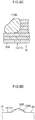
Fig. 8A is a plan view illustrating a second weld portion of a comparative example. -
Fig. 8B is a side view illustrating a second weld portion of a comparative example. -
Fig. 8C is a cross-section taken along line Y-Y inFig. 8B , illustrating a second weld portion of a comparative example. -
Fig. 8D is a bottom view illustrating a second weld portion of a comparative example. - Explanation follows regarding a laminated iron core and a manufacturing method thereof according to an exemplary embodiment of the present invention.
- First, explanation follows regarding a
laminated iron core 10 according to the present exemplary embodiment. Thelaminated iron core 10 is a laminated rotor core employed in the rotor of a vehicle drive motor (an electric motor), and is an element configuring a magnetic rotor. As illustrated inFig. 1 , plural ring-shapediron core pieces 14, each configured by arranging four separate circular arc-shaped iron core pieces 12 (divided iron core pieces) in a ring shape, are laminated on one another to configure a laminatediron core body 16. Thelaminated iron core 10 is formed by integrating the laminatediron core body 16 usingplural weld portions 18. - In the present exemplary embodiment, each of the circular arc-shaped
iron core pieces 12 is made of magnetic sheet steel, and is set with a circular arc angle θ of 90°. Plural (four in this example) circular arc shaped magnet mounting portions 20 (magnetic pole pieces) arranged around a circumferential direction are formed at a circumferential outside of each of the circular arc-shapediron core pieces 12. Themagnet mounting portions 20 are each set with a circular arc angle δ of 22.5°, and amagnet mounting hole 22 for mounting a magnet is formed through each of themagnet mounting portions 20. - Moreover, plural (four in this example) circular guide holes 24 arranged around the circumferential direction are formed in a width direction intermediate portion (intermediate portion between the outer circumference and the inner circumference) of each of the circular arc-shaped
iron core pieces 12. The guide holes 24 are pilot holes for insertion of guide pins 68 (seeFig. 5 ) that are provided to analignment jig 62 employed when laminating the plural ring-shapediron core pieces 14 and when welding the laminatediron core body 16. - The guide holes 24 and the
magnet mounting portions 20 are respectively provided so as to be disposed at intervals of 22.5° in a state in which the circular arc-shapediron core pieces 12 have been arranged in a ring shape to configure one of the ring-shapediron core pieces 14. The guide holes 24 are provided in-phase with themagnet mounting portions 20 around the circumferential direction of the ring-shapediron core piece 14. - As illustrated in
Fig. 2 , the mutually overlapping ring-shapediron core pieces 14 are laminated in a specific number of layers using a so-called bricklaying technique, in which circumferential direction joints 26 between the circular arc-shapediron core pieces 12 are phase-offset with respect to each other around the circumferential direction. In the present exemplary embodiment, the phase-offset angle is set to 22.5°, this being the same as the circular arc angle δ of themagnet mounting portions 20. - By laminating the ring-shaped
iron core pieces 14 with a phase-offset of 22.5°, themagnet mounting portions 20 and the guide holes 24 are disposed at intervals of 22.5°, such that the positions of the respectivemagnet mounting portions 20 and guideholes 24 are aligned along a lamination direction of the ring-shaped iron core pieces 14 (hereafter simply referred to as the lamination direction). Themagnet mounting portions 20 and the guide holes 24 thus penetrate from one lamination direction end side to the other lamination direction end side of the laminatediron core body 16. - As illustrated in
Fig. 1 , the plural ring-shapediron core pieces 14 that have been laminated as described above are joined together by theplural weld portions 18. Theplural weld portions 18 are provided at a face on the opposite side of the guide holes 24 to themagnet mounting portions 20, namely, at the circumferential inside of the laminatediron core body 16. To explain in more detail, therespective weld portions 18 are provided ingrooves 28 formed at the circumferential inside of the respective ring-shapediron core pieces 14 at positions aligned with the guide holes 24. Each of theweld portions 18 include a linearfirst weld portion 18A running along the lamination direction of the laminatediron core body 16, and linearsecond weld portions 18B provided at some of the ring-shapediron core pieces 14, including a ring-shapediron core piece 14 at an outermost layer, and extending toward the lamination direction inside (seeFig. 3A ). - Note that prior to providing the
weld portions 18, pluralmeltable protrusions 30 are formed projecting out from each of thegrooves 28. As illustrated inFig. 3B , themeltable protrusions 30 include afirst protrusion 30A provided at a central side of each of the correspondinggroove 28 when viewed from above, andsecond protrusions 30B provided on both circumferential direction sides of thefirst protrusion 30A. Thesecond protrusions 30B are each formed at a position offset by approximately 3° to 4° from thefirst protrusion 30A in plan view. - As illustrated in
Fig. 1 , plural of thefirst weld portions 18A are provided arranged around the circumferential direction at the circumferential inside of the laminatediron core body 16. In the present exemplary embodiment, the number offirst weld portions 18A is the same as the number of magnetic poles provided at the laminated iron core body 16 (sixteen in this example). Namely, thefirst weld portions 18A are provided at intervals of 22.5° around the circumferential inside of the laminatediron core body 16. Thefirst weld portions 18A are provided at positions corresponding to thefirst protrusions 30A, thefirst protrusions 30A being melted during formation of thefirst weld portions 18A, in other words during welding. Thefirst weld portions 18A weld (join) together the respective layers of circular arc-shapediron core pieces 12, which are phase-offset with respect to each other around the circumferential direction, along the lamination direction. - The
second weld portions 18B are provided adjacent to the respectivefirst weld portions 18A at the circumferential inside of the laminatediron core body 16. The same number of thesecond weld portions 18B as the number offirst weld portions 18A (sixteen in this example) is provided at each lamination direction side (at an upper portion and a lower portion) of the laminatediron core body 16. Namely, thesecond weld portions 18B are provided at the circumferential inside of the laminatediron core body 16 at intervals of 22.5° at both the upper portion and the lower portion of the laminatediron core body 16. Thesecond weld portions 18B are provided at positions corresponding to thesecond protrusions 30B, thesecond protrusions 30B corresponding to thesecond weld portions 18B being melted during formation of thesecond weld portions 18B, in other words during welding. - The
second weld portions 18B at the upper portion of the laminatediron core body 16 are provided 3° to 4° counterclockwise from the respectivefirst weld portions 18A in plan view. Thesecond weld portions 18B at the lower portion of the laminatediron core body 16 are provided 3° to 4° clockwise from the respectivefirst weld portions 18A in plan view. Thesecond weld portions 18B extend for a length of several millimeters from the upper faces of the laminatediron core body 16 so as to weld (join) together plural (approximately ten in this example) of the ring-shapediron core pieces 14, including the ring-shapediron core pieces 14 of the outermost layers, along the lamination direction. -
Fig. 4A to Fig. 4D are enlarged diagrams of one of thesecond weld portions 18B. In a welded state, thesecond weld portion 18B of the present exemplary embodiment has the following properties. Namely, as illustrated inFig. 4B , thesecond weld portion 18B is formed so as to taper on progression toward a lowerside end portion 19C at the lamination direction inside thereof. - As illustrated in
Fig. 4B andFig. 4C , an upperside end portion 19A of thesecond weld portion 18B is positioned further toward the lamination direction inside than a lamination direction outside end face (upper face) of the laminatediron core body 16. Namely, the lamination direction outsideend portion 19A of thesecond weld portion 18B is formed so as not to project out beyond the lamination direction outside end face (upper face) of the laminatediron core body 16. - As illustrated in
Fig. 4A andFig. 4D , thesecond weld portion 18B does not project out beyond thesecond protrusion 30B in either plan view or bottom view. As illustrated inFig. 3A , anend portion 19B of thesecond weld portion 18B at a radial direction inside of the laminatediron core body 16 is positioned further within the laminatediron core body 16 than a circle S inscribed at an innercircumferential face 32 of the laminatediron core body 16. Namely, the radial direction insideend portion 19B of thesecond weld portion 18B is formed so as not to project out beyond the circle S inscribed at the innercircumferential face 32 of the laminatediron core body 16. Note that in the present exemplary embodiment, a radial direction inside end portion of thefirst weld portion 18A is also formed so as not to project out beyond the circle S inscribed at the innercircumferential face 32 of the laminatediron core body 16. - Next, explanation follows regarding a method of manufacturing the
laminated iron core 10 with the above configuration. - The method of manufacturing the
laminated iron core 10 is configured by: a pressing process, this being a first process; a laminating process, this being a second process; a welding process, this being a third process; and an inspection process, this being a fourth process. - In the pressing process, a strip shaped magnetic steel sheet is pressed by a die to manufacture a carrier-mounted single sheet (not illustrated in the drawings) in which plural of the circular arc-shaped
iron core pieces 12 are coupled together by pairs of coupling portions. The manufactured carrier-mounted single sheet is wound onto a reel (not illustrated in the drawings), and then processing transitions to the laminating process. - In the laminating process, the circular arc-shaped
iron core pieces 12 are sequentially cut out from the carrier-mounted single sheet as it is conveyed, after which the cutout circular arc-shapediron core pieces 12 are arranged in ring shapes to form the ring-shapediron core pieces 14, while laminating the plural ring-shapediron core pieces 14 so as to be phase-offset with respect to one another around the circumferential direction in order to manufacture the laminatediron core body 16. Specifically, the circular arc-shapediron core pieces 12 that have been cut out from the carrier-mountedsingle sheet 30 are placed on the alignment jig 62 (seeFig. 5 ) that is detachably attached to a turntable of an electric indexer (not illustrated in the drawings). As illustrated inFig. 5 , thealignment jig 62 includes a ring shapedlower plate 64, plural (sixteen in this example) of the guide pins 68 (pilot pins) that project out upward from thelower plate 64, and plural (eight in this example)support columns 70 that project out upward from thealignment jig 62. Note that the numbers of the guide pins 68 and thesupport columns 70 may be modified as appropriate. - The sixteen guide pins 68 are arranged around the circumferential direction of the
lower plate 64 at uniform spacings (at spacings of 22.5°) and securely fixed to thelower plate 64. The eightsupport columns 70, which are further to the circumferential inside of thelower plate 64 than the sixteen guide pins 68, are arranged around the circumferential direction of thelower plate 64 at uniform spacings (at spacings of 45°), and are securely fixed to thelower plate 64. Note that although thealignment jig 62 is configured including a ring shapedupper plate 72 illustrated inFig. 6 , in the laminating process thealignment jig 62 is employed in a state in which this upper plate has been removed. - As illustrated in
Fig. 5 , each of the circular arc-shapediron core pieces 12 that has been pushed onto thealignment jig 62 is retained on thealignment jig 62 in a state in which the respective guide pins 68 have been inserted through its four guide holes 24. Each time one of the circular arc-shapediron core pieces 12 is pushed onto thealignment jig 62, thealignment jig 62 is rotated 90° (the circular arc angle θ of the circular arc-shaped iron core pieces 12) in the arrow A direction inFig. 5 . One layer of the ring-shapediron core pieces 14 is completed by repeating this 90° rotation three times. Next, thealignment jig 62 is lowered by an amount corresponding to the plate thickness of a single circular arc-shapediron core piece 12, and thealignment jig 62 is rotated 22.5° (the phase-offset angle δ) in the arrow A direction inFig. 5 . By sequentially repeating the above processing, the plural ring-shapediron core pieces 14 are laminated (rotationally laminated) so as to be phase-offset with respect to each other around the circumferential direction in order to manufacture the laminatediron core body 16. - Note that when the laminated
iron core body 16 has been manufactured, the circumferential direction positions of thefirst protrusions 30A and thesecond protrusions 30B of the ring-shapediron core pieces 14 are aligned with each other. Namely, thefirst protrusions 30A and thesecond protrusions 30B form rows along the lamination direction. The manufactured laminatediron core body 16 is then removed from the turntable together with thealignment jig 62, and processing transitions to the welding process. - In the welding process, the respective layers of the circular arc-shaped
iron core pieces 12, which are phase-offset with respect to each other around the circumferential direction, are welded together along the lamination direction at plural circumferential direction locations at the circumferential inside of the laminatediron core body 16. First, as illustrated inFig. 6 , theupper plate 72 is attached to thealignment jig 62. Theupper plate 72 is fixed to upper ends of the eightsupport columns 70, for example by fastening with bolts, thereby retaining the laminatediron core body 16 at a specific thickness. Alternatively, the laminatediron core body 16 may be retained at the specific thickness by a dedicated clamping device that clamps theupper plate 72 and thelower plate 64 above and below the eightsupport columns 70. - Next, as illustrated in
Fig. 6 , thealignment jig 62 is attached onto aturntable 74 that includes a fiber laser welding torch, and the welding previously described is performed using the fiber laser welding torch (note that the member allocated thereference numeral 76 inFig. 6 is a torch serving as a processing head of the fiber laser welding torch). Note that the welding processing includes a first welding process to form thefirst weld portions 18A, and a second welding process to form thesecond weld portions 18B. - As illustrated in
Fig. 7 , in the first welding process, thetorch 76 is tilted upward, namely toward the lamination direction outside, by 45° with respect to the laminatediron core body 16, while moving thetorch 76 downward along the lamination direction (the arrow B direction) to weld the laminated ring-shapediron core pieces 14 together. Specifically, in the first welding process, a welding laser is continuously or intermittently scanned across each of thefirst protrusions 30A disposed along the lamination direction on progression from the ring-shapediron core piece 14 at the uppermost layer to the ring-shapediron core piece 14 at the lowermost layer. Thefirst protrusions 30A scanned by the laser melt as a result, thus forming the linearfirst weld portion 18A. - Next, the
turntable 74 is rotated by 22.5° (the phase-offset angle δ) in the arrow A direction inFig. 6 , and the welding laser is scanned across the nextfirst protrusions 30A in order to form the nextfirst weld portion 18A. The above processing is sequentially repeated to form the sixteenfirst weld portions 18A at the circumferential inside of the laminatediron core body 16. - The second welding process is performed following the first welding process. As illustrated in
Fig. 7 , similarly to in the first welding process, in the second welding process thetorch 76 is tilted upward, namely toward the lamination direction outside, by 45° with respect to the laminatediron core body 16, while moving thetorch 76 downward along the lamination direction (the arrow B direction) in order to weld the plural layers of the laminated ring-shapediron core pieces 14 together. Specifically, in the second welding process, the welding laser is scanned across each of thesecond protrusions 30B of the ring-shapediron core pieces 14 from the lamination direction outside at an oblique angle, specifically from an oblique upward angle of 45°. When this is performed, thesecond protrusions 30B scanned with the laser are thesecond protrusions 30B disposed on the counterclockwise side of the correspondingfirst protrusions 30A as viewed from above. - Note that in the second welding process of the present exemplary embodiment, a direction of heat input matches the laser beam direction, and is tilted at an oblique angle with respect to the lamination direction. Although the direction of the
torch 76 with respect to the laminatediron core body 16 matches the beam direction of the laser, namely the direction of heat input, inFig. 7 , there is no limitation thereto. As long as the laser is scanned while tilted to an oblique angle with respect to the lamination direction, thetorch 76 itself does not need to be tilted to an oblique angle with respect to the lamination direction. - The
torch 76 is then moved downward along the lamination direction (arrow B direction) by several millimeters. Namely, the welding laser is continuously or intermittently scanned across an upper end side portion of thesecond protrusions 30B disposed running along the lamination direction, from the ring-shapediron core piece 14 at the uppermost layer toward the ring-shapediron core piece 14 at the lowermost layer. Thesecond protrusions 30B scanned by the laser melt as a result, thus forming the linearsecond weld portion 18B. Note that in the second welding process, the welding heat input amount is reduced as thetorch 76 moves from the lamination direction outside toward the lamination direction inside. Thus, as illustrated inFig. 4B , thesecond weld portion 18B tapers on progression toward the lowerside end portion 19C at the lamination direction inside. - Next, the
turntable 74 is rotated by 22.5° (the phase-offset angle δ) in the arrow A direction inFig. 6 and the welding laser is scanned across the nextsecond protrusions 30B to form the nextsecond weld portion 18B. The above processing is sequentially repeated to form the sixteensecond weld portions 18B at the circumferential inside of the upper portion of the laminatediron core body 16. - An operator then separates the
upper plate 72 and thelower plate 64, removes the laminatediron core body 16 from thealignment jig 62, turns the laminatediron core body 16 upside-down, then fixes the laminatediron core body 16 to thealignment jig 62 once again. The second welding process is then repeated after theupper plate 72 has been reattached to thealignment jig 62. Namely, the sixteensecond weld portions 18B are formed at the circumferential inside of the upper portion (which was the lower portion during the first round of the second welding process) of the laminated iron core body 16 (seeFig. 1 ). - By performing the first welding process and the second welding process, the
first weld portions 18A and thesecond weld portion 18B are formed, thus completing thelaminated iron core 10. The completed laminated iron core then undergoes a specific inspection in the next process, this being the inspection process. - Next, explanation follows regarding operation and advantageous effects of the present exemplary embodiment.
- In the
laminated iron core 10 of the present exemplary embodiment, after performing the laminating process, the ring-shapediron core pieces 14 are joined together in the lamination direction in the first welding process and the second welding process. Note that thefirst weld portions 18A formed in the first welding process are linear weld portions provided along the lamination direction of the laminatediron core body 16. Thefirst weld portions 18A join the ring-shapediron core pieces 14 of the respective layers into an integral unit. Thesecond weld portions 18B formed in the second welding process are provided at some of the ring-shapediron core pieces 14, including the ring-shapediron core piece 14 at the corresponding outermost layer, and are linear weld portions that extend toward the lamination direction inside. Thesecond weld portions 18B join together the ring-shapediron core pieces 14 in some of the layers, including the ring-shapediron core piece 14 at the corresponding outermost layer. - Note that the ring-shaped
iron core piece 14 of any given intermediate layer is welded to the ring-shapediron core pieces 14 of the two adjacent layers, whereas the ring-shapediron core pieces 14 of the outermost layers are only welded to the ring-shapediron core piece 14 of the adjacent layer on one side thereof. Thus, were the laminatediron core body 16 to be formed with only thefirst weld portions 18A, and thelaminated iron core 10 configured from this laminatediron core body 16 then to be used in a motor rotor, the following defect may arise. Namely, depending on the usage environment, the ring-shapediron core pieces 14 of the outermost layers may shift or detach from the laminatediron core body 16. To address this, thesecond weld portions 18B of the present exemplary embodiment enable the join strength to be enhanced at the ring-shapediron core pieces 14 of the respective outermost layers of the laminatediron core body 16. - Moreover, laser welding is performed from the lamination direction outside toward the lamination direction inside in the second welding process, such that the
second weld portions 18B extend from the ring-shapediron core pieces 14 of the respective outermost layers toward the lamination direction inside.Fig. 8A to Fig. 8D illustrate a comparative example in which asecond weld portion 118B has been laser spot welded by shining a laser at a single location. As illustrated inFig. 8B andFig. 8C , thesecond weld portion 118B of the comparative example projects out beyond the upper face of the laminatediron core body 16. In contrast thereto, in the present exemplary embodiment, thesecond weld portion 18B is formed from the lamination direction outside toward the lamination direction inside. Thus, as illustrated inFig. 4B andFig. 4C , thesecond weld portion 18B is suppressed from projecting out beyond the upper face of the laminatediron core body 16. The present exemplary embodiment is therefore capable of enhancing the join strength of the ring-shapediron core pieces 14 of the respective outermost layers, and of suppressing shifting or detachment of the ring-shapediron core pieces 14, without causing the weld portions to project out beyond the upper face of the laminatediron core body 16. - Moreover, in the second welding process, each of the
second weld portions 18B is formed by reducing the welding heat input amount as thetorch 76 is moved downward toward the lamination direction inside. Note that if the welding heat input amount were not changed as thetorch 76 moves, a molten portion would remain at a lower side end portion of thesecond weld portion 18B, which would be liable to project out toward the circumferential inside of the laminatediron core body 16. In the present exemplary embodiment, reducing the welding heat input amount as thetorch 76 is moved downward causes thesecond weld portion 18B to taper on progression toward the lowerside end portion 19C at the lamination direction inside, as illustrated inFig. 4B . As illustrated inFig. 3A , the radial direction insideend portion 19B of thesecond weld portion 18B formed in this manner does not project out toward the circumferential inside of the laminatediron core body 16. Furthermore, the radial direction insideend portion 19B of thesecond weld portion 18B does not project out beyond the circle S inscribed at the innercircumferential face 32 of the laminatediron core body 16. - In the present exemplary embodiment, the
second weld portions 18B, these being additional weld portions, do not project out beyond either the upper face or lower face, these being lamination direction outside faces, of the laminatediron core body 16, and do not project out beyond the circle S inscribed at the innercircumferential face 32 of the laminatediron core body 16, thereby obtaining the following advantageous effects. Namely, the present exemplary embodiment is capable of enhancing the join strength of the ring-shapediron core pieces 14 at the respective outermost layers, while suppressing any reduction in assembly precision when assembling thelaminated iron core 10 configured from the laminatediron core body 16 to a rotor shaft or the like. - Furthermore, in the second welding process of the present exemplary embodiment the welding laser is scanned at an oblique upward tilt of 45° with respect to the laminated
iron core body 16 along a direction of progress from the lamination direction outside. Directing the direction of heat input along the welding direction enables the next location to be welded to be preheated, thus enabling a wider weld bead and enhanced weld strength. Furthermore, as illustrated inFig. 4B , in cases in which the welding direction coincides with the direction of gravity, molten material flows along the welding direction, resulting in a desirable duration between melting and solidification, and thus imparting the weld bead with a smooth surface. - In the welding process of the present exemplary embodiment, the
second weld portions 18B can be provided at both lamination direction sides by forming thesecond weld portions 18B from one welding direction outside, inverting the laminatediron core body 16, and then forming thesecond weld portions 18B from the other welding direction outside. This enables the join strength of the ring-shapediron core pieces 14 of the respective outermost layers to be enhanced, enabling the ring-shapediron core pieces 14 to be suppressed from shifting or detaching. - Although the laminated
iron core body 16 is fixed to thealignment jig 62 and laser welding is performed with the lamination direction aligned with the up-down direction (direction of gravity) as illustrated inFig. 6 in the present exemplary embodiment, there is no limitation thereto. The lamination direction may be set and welding performed in a horizontal direction or an oblique direction. - Although laser welding is employed as the method of joining the plural layers of ring-shaped
iron core pieces 14 in the present exemplary embodiment, there is no limitation thereto, and another method may be employed. For example, a method other than laser welding, such as electron beam welding, light beam welding, or arc welding, may be employed. Note that in cases in which a welding method such as electron beam welding or light beam welding is employed, the torch corresponds to a processing head, and the direction of heat input matches the beam direction. Note that in cases in which a welding method such as arc welding is employed, the electrode rod corresponds to a processing head and the direction of heat input matches the arc electrical discharge direction. - Although sixteen of the
second weld portions 18B are formed after forming the sixteenfirst weld portions 18A in the present exemplary embodiment, there is no limitation thereto. Thefirst weld portions 18A and thesecond weld portions 18B may be alternately formed at an upper portion of the laminatediron core body 16. - Although the
second weld portions 18B are provided counterclockwise of the respectivefirst weld portions 18A at the upper portion of the laminatediron core body 16 in plan view, and provided clockwise of the respectivefirst weld portions 18A at the lower portion of the laminatediron core body 16 in plan view in the present exemplary embodiment, there is no limitation thereto. For example, thesecond weld portions 18B may be provided clockwise of the respectivefirst weld portions 18A at the upper portion of the laminatediron core body 16 in plan view, and provided counterclockwise of the respectivefirst weld portions 18A at the lower portion of the laminatediron core body 16 in plan view. Alternatively, for example, thesecond weld portions 18B may be provided in the same direction relative to the respectivefirst weld portions 18A at both the upper portion and the lower portion of the laminatediron core body 16 in plan view. Alternatively, thesecond weld portions 18B may be provided at both sides of the respectivefirst weld portions 18A at both the upper portion and the lower portion of the laminatediron core body 16 in plan view, namely at thirty-two locations respectively in the present exemplary embodiment. Note that in consideration of the welding process, the welding process can be simplified by forming thesecond weld portions 18B at uniform angular intervals around the circumferential direction. - Moreover, in the present exemplary embodiment, forming both the
first weld portions 18A and thesecond weld portions 18B at uniform angular intervals around the circumferential direction enables thelaminated iron core 10 to be provided with a good rotational balance. - Regarding the weld positions of the respective circular arc-shaped
iron core pieces 12, thesecond weld portions 18B should be formed toward the sides of the joints 26 (seeFig. 1 ), namely toward the circumferential direction outer sides of theiron core piece 12. Providing thesecond weld portions 18B as far toward these outer sides as possible enables enhanced join strength with respect to centrifugal force that acts on thelaminated iron core 10. - Although three meltable protrusions 30 (the
first protrusion 30A and thesecond protrusions 30B) are provided for eachsingle groove 28 in the present exemplary embodiment, there is no limitation thereto. A groove may be provided for eachfirst protrusion 30A and for eachsecond protrusion 30B. In such cases, if there is only a short distance between thefirst protrusion 30A and the respectivesecond protrusions 30B, projecting locations between neighboring grooves may deform or the like during welding, which may create weak points. Thus, in cases in which there is only a short distance between thefirst protrusion 30A and the respectivesecond protrusions 30B, thefirst protrusion 30A and thesecond protrusions 30B are preferably formed projecting out from asingle groove 28 as in the present exemplary embodiment. - Although the laminated
iron core body 16 is configured with sixteen poles in the present exemplary embodiment, the present invention is not limited thereto, and the number of magnetic poles in the laminatediron core body 16 may be modified as appropriate. - Although the present exemplary embodiment is applied with a configuration in which the number of
weld portions 18 provided is the same as the number of the magnetic poles of the laminatediron core body 16, there is no limitation thereto, and the number ofweld portions 18 may be modified as appropriate. For example, a configuration may be applied in which the number of weld portions provided is half the number of the magnetic poles of the laminatediron core body 16. - Although the present exemplary embodiment is applied with a configuration in which the
weld portions 18 and themagnet mounting portions 20 are provided on opposite sides of the guide holes 24 to each other, there is no limitation thereto. A configuration may be applied in which the weld portions and the guide holes are provided offset with respect to each other around the circumferential direction of the circular arc-shaped iron core pieces. - Although the present exemplary embodiment is applied with a configuration in which the
weld portions 18 are provided at the circumferential inside of the laminatediron core body 16, there is no limitation thereto. The weld portions may be provided at the circumferential outside of the laminated iron core body. In such cases, the weld portions including the first weld portions and the second weld portions are formed such that radial direction outside end portions thereof do not project out beyond a circumscribed circle at an outer circumferential face of the laminated iron core body. - Various other modifications may be implemented within a range not departing from the spirit of the present invention. Obviously, the scope of rights encompassed by the present invention is not limited to the above exemplary embodiment.
- The entire content of the disclosure of
Japanese Patent Application No. 2018-248037 filed on December 28, 2018
Claims (8)
- A laminated iron core comprising:a ring-shaped iron core piece configured by arranging magnetic circular arc-shaped iron core pieces in a ring shape;a laminated iron core body formed by laminating a plurality of ring-shaped iron core pieces;a first weld portion provided at the laminated iron core body so as to run along a lamination direction of the ring-shaped iron core pieces; anda second weld portion provided at some of the plurality of ring-shaped iron core pieces, including a ring-shaped iron core piece at an outermost layer, the second weld portion extending toward a lamination direction inside.
- The laminated iron core of claim 1, wherein the second weld portion tapers on progression toward a lamination direction inside end portion of the second weld portion.
- The laminated iron core of claim 1 or claim 2, wherein a lamination direction outside end portion of the second weld portion is positioned either at a same position as a lamination direction outside end face of the laminated iron core body, or at the lamination direction inside of the end face.
- The laminated iron core of any one of claim 1 to claim 3, wherein
an end portion of the second weld portion in a radial direction of the laminated iron core body is positioned either at a same position as a circle contacting a circumferential face on a side of the laminated iron core body where the second weld portion is provided, or further within the laminated iron core body than the circle. - A laminated iron core manufacturing method comprising:a lamination process of laminating a plurality of ring-shaped iron core pieces to form a laminated iron core body while arranging magnetic circular arc-shaped iron core pieces in a ring shape to form the ring-shaped iron core pieces;a first welding process of welding the laminated iron core body along a lamination direction of the ring-shaped iron core pieces; anda second welding process of welding some of the ring-shaped iron core pieces, including a ring-shaped iron core piece at an outermost layer, from a lamination direction outside toward a lamination direction inside.
- The laminated iron core manufacturing method of claim 5, wherein, in the second welding process, a welding heat input amount is reduced on progression toward the lamination direction inside.
- The laminated iron core manufacturing method of claim 5 or claim 6, wherein, in the second welding process, a direction of heat input to the laminated iron core body is tilted at an oblique angle relative to the lamination direction.
- The laminated iron core manufacturing method of any one of claim 5 to claim 7, wherein:the second welding process is performed on the ring-shaped iron core piece at the outermost layer on one out of two lamination direction sides; andthe laminated iron core body is then inverted in the lamination direction, after which the second welding process is performed on the ring-shaped iron core piece at the outermost layer on the other out of the two lamination direction sides.
Applications Claiming Priority (2)
| Application Number | Priority Date | Filing Date | Title |
|---|---|---|---|
| JP2018248037 | 2018-12-28 | ||
| PCT/JP2019/051312 WO2020138372A1 (en) | 2018-12-28 | 2019-12-26 | Laminated iron core and production method for laminated iron core |
Publications (2)
| Publication Number | Publication Date |
|---|---|
| EP3905492A1 true EP3905492A1 (en) | 2021-11-03 |
| EP3905492A4 EP3905492A4 (en) | 2022-10-05 |
Family
ID=71129127
Family Applications (1)
| Application Number | Title | Priority Date | Filing Date |
|---|---|---|---|
| EP19902516.4A Pending EP3905492A4 (en) | 2018-12-28 | 2019-12-26 | LAMINATED IRON CORE AND METHOD OF MAKING A LAMINATED IRON CORE |
Country Status (4)
| Country | Link |
|---|---|
| EP (1) | EP3905492A4 (en) |
| JP (1) | JP6965465B2 (en) |
| CN (1) | CN113491058B (en) |
| WO (1) | WO2020138372A1 (en) |
Families Citing this family (2)
| Publication number | Priority date | Publication date | Assignee | Title |
|---|---|---|---|---|
| JP2024060339A (en) * | 2022-10-19 | 2024-05-02 | 日本発條株式会社 | Laminated core and its manufacturing method |
| EP4607775A4 (en) * | 2022-10-19 | 2026-02-18 | Nhk Spring Co Ltd | METHOD AND DEVICE FOR INSPECTING A LAMINATED IRON CORE AND REPAIR METHOD AND DEVICE |
Family Cites Families (21)
| Publication number | Priority date | Publication date | Assignee | Title |
|---|---|---|---|---|
| JPS6040111A (en) * | 1983-08-15 | 1985-03-02 | Asahi Chem Ind Co Ltd | Novel graft copolymer and its preparation |
| JPH09163691A (en) * | 1995-12-01 | 1997-06-20 | Toshiba Mec Kk | Laminated core and manufacturing method thereof |
| JP2010011645A (en) * | 2008-06-27 | 2010-01-14 | Daikin Ind Ltd | Laminated iron core, motor and compressor |
| JP5213821B2 (en) * | 2009-02-04 | 2013-06-19 | 三菱電機株式会社 | Rotating electric machine |
| JP5341614B2 (en) * | 2009-05-14 | 2013-11-13 | 株式会社三井ハイテック | Manufacturing method of laminated iron core and laminated iron core |
| JP5971418B2 (en) * | 2013-06-26 | 2016-08-17 | 日産自動車株式会社 | Synchronous rotor for rotating electrical machine and method for manufacturing synchronized rotor for rotating electrical machine |
| JP6164039B2 (en) * | 2013-10-21 | 2017-07-19 | アイシン・エィ・ダブリュ株式会社 | Manufacturing method of laminated iron core |
| CN203747521U (en) * | 2013-12-25 | 2014-07-30 | 比亚迪股份有限公司 | Stator cores for motors and motors |
| JP6469355B2 (en) | 2014-04-17 | 2019-02-13 | 日本発條株式会社 | Manufacturing method of laminated iron core of vehicle drive motor |
| US10193426B2 (en) * | 2014-07-25 | 2019-01-29 | Nhk Spring Co., Ltd. | Method for manufacturing a stacked iron core of a vehicle drive motor |
| KR101923359B1 (en) * | 2015-11-25 | 2018-11-28 | 미쓰비시덴키 가부시키가이샤 | Manufacturing method of rotary electric and rotary electric |
| JP6653560B2 (en) * | 2015-12-11 | 2020-02-26 | 株式会社三井ハイテック | Stator laminated iron core and method of manufacturing the same |
| EP3399629B1 (en) * | 2016-03-14 | 2020-11-11 | Aisin Aw Co., Ltd. | Rotor manufacturing method |
| JP6659161B2 (en) * | 2016-03-15 | 2020-03-04 | 三菱電機株式会社 | Split core of rotary electric machine, method of manufacturing the split core, and rotary electric machine |
| JP6652190B2 (en) * | 2016-03-28 | 2020-02-19 | アイシン・エィ・ダブリュ株式会社 | Method of manufacturing rotor |
| DE102016208692A1 (en) * | 2016-05-20 | 2017-11-23 | Zf Friedrichshafen Ag | Rotor of an electric machine with a laminated core |
| JP6934714B2 (en) * | 2016-10-18 | 2021-09-15 | 株式会社三井ハイテック | Manufacturing method of laminated iron core and laminated iron core |
| JP6763796B2 (en) * | 2017-02-02 | 2020-09-30 | 東芝産業機器システム株式会社 | Manufacturing method of laminated iron core |
| US11764654B2 (en) * | 2017-03-09 | 2023-09-19 | Aisin Corporation | Rotary electric machine member manufacturing method |
| WO2019111414A1 (en) * | 2017-12-08 | 2019-06-13 | 日産自動車株式会社 | Rotor core for rotating electric machine and method for manufacturing rotor core for rotating electric machine |
| JP6633171B1 (en) * | 2018-11-30 | 2020-01-22 | 三菱電機株式会社 | Laminated core, stator and rotor |
-
2019
- 2019-12-26 WO PCT/JP2019/051312 patent/WO2020138372A1/en not_active Ceased
- 2019-12-26 EP EP19902516.4A patent/EP3905492A4/en active Pending
- 2019-12-26 JP JP2020562464A patent/JP6965465B2/en active Active
- 2019-12-26 CN CN201980085742.XA patent/CN113491058B/en active Active
Also Published As
| Publication number | Publication date |
|---|---|
| JPWO2020138372A1 (en) | 2021-09-27 |
| EP3905492A4 (en) | 2022-10-05 |
| CN113491058B (en) | 2023-09-26 |
| JP6965465B2 (en) | 2021-11-10 |
| WO2020138372A1 (en) | 2020-07-02 |
| CN113491058A (en) | 2021-10-08 |
Similar Documents
| Publication | Publication Date | Title |
|---|---|---|
| KR101307097B1 (en) | Rotor and method of manufacturing the rotor | |
| US10193426B2 (en) | Method for manufacturing a stacked iron core of a vehicle drive motor | |
| CN102292898B (en) | Rotor and method for manufacturing same | |
| US10505432B2 (en) | Rotor and method for manufacturing rotor | |
| JP6652190B2 (en) | Method of manufacturing rotor | |
| JP6483079B2 (en) | Electrical conductor joining method | |
| US12390881B2 (en) | Laser welding method | |
| US12176771B2 (en) | Conductor wire insulating film separating method | |
| JP2020114062A (en) | Stator of rotating electric machine and manufacturing method thereof | |
| WO2021144900A1 (en) | Stator and method for manufacturing stator | |
| JP6965465B2 (en) | Manufacturing method of laminated iron core and laminated iron core | |
| JP2021069245A (en) | Rotary electric machine and method for manufacturing rotary electric machine | |
| JP2023098255A (en) | Rotary electric machine | |
| JP2004007949A (en) | Induction motor rotor | |
| JP2012205444A (en) | Stator core, method for manufacturing the same, and motor | |
| JP2015208066A (en) | Method of manufacturing lamination iron core of vehicle driving motor | |
| JP2017040368A (en) | Joining method of core ring of torque converter, manufacturing method of torque converter, and torque converter manufactured by using the same | |
| JP5717555B2 (en) | Stator core | |
| CN111247714A (en) | Armature iron core of rotating electrical machine, iron core block connection body, and manufacturing method of armature iron core of rotating electrical machine | |
| JP6917325B2 (en) | Manufacturing method of laminated iron core for vehicle drive motor and laminated iron core | |
| WO2024095406A1 (en) | Stator core for rotating electrical machine, stator, and rotating electrical machine | |
| JP2001037112A (en) | Magnet motor stator | |
| CN111557071A (en) | Method for manufacturing rotor | |
| JPWO2020053998A1 (en) | Laminated iron core | |
| CN111264016A (en) | Core block coupling body and method for manufacturing armature core of rotating electrical machine |
Legal Events
| Date | Code | Title | Description |
|---|---|---|---|
| STAA | Information on the status of an ep patent application or granted ep patent |
Free format text: STATUS: THE INTERNATIONAL PUBLICATION HAS BEEN MADE |
|
| PUAI | Public reference made under article 153(3) epc to a published international application that has entered the european phase |
Free format text: ORIGINAL CODE: 0009012 |
|
| STAA | Information on the status of an ep patent application or granted ep patent |
Free format text: STATUS: REQUEST FOR EXAMINATION WAS MADE |
|
| 17P | Request for examination filed |
Effective date: 20210701 |
|
| AK | Designated contracting states |
Kind code of ref document: A1 Designated state(s): AL AT BE BG CH CY CZ DE DK EE ES FI FR GB GR HR HU IE IS IT LI LT LU LV MC MK MT NL NO PL PT RO RS SE SI SK SM TR |
|
| RAP3 | Party data changed (applicant data changed or rights of an application transferred) |
Owner name: RENAULT S.A.S Owner name: NISSAN MOTOR CO., LTD. Owner name: NHK SPRING CO., LTD. |
|
| DAV | Request for validation of the european patent (deleted) | ||
| DAX | Request for extension of the european patent (deleted) | ||
| RAP3 | Party data changed (applicant data changed or rights of an application transferred) |
Owner name: RENAULT S.A.S Owner name: NISSAN MOTOR CO., LTD. Owner name: NHK SPRING CO., LTD. |
|
| REG | Reference to a national code |
Ref country code: DE Ref legal event code: R079 Free format text: PREVIOUS MAIN CLASS: H02K0015020000 Ipc: H02K0015030000 |
|
| A4 | Supplementary search report drawn up and despatched |
Effective date: 20220905 |
|
| RIC1 | Information provided on ipc code assigned before grant |
Ipc: H02K 1/276 20220101ALI20220830BHEP Ipc: H02K 15/03 20060101AFI20220830BHEP |
|
| STAA | Information on the status of an ep patent application or granted ep patent |
Free format text: STATUS: EXAMINATION IS IN PROGRESS |
|
| 17Q | First examination report despatched |
Effective date: 20241211 |