EP3905470A1 - Filtervorrichtung - Google Patents
Filtervorrichtung Download PDFInfo
- Publication number
- EP3905470A1 EP3905470A1 EP20172508.2A EP20172508A EP3905470A1 EP 3905470 A1 EP3905470 A1 EP 3905470A1 EP 20172508 A EP20172508 A EP 20172508A EP 3905470 A1 EP3905470 A1 EP 3905470A1
- Authority
- EP
- European Patent Office
- Prior art keywords
- filter device
- filter
- toroidal core
- cables
- capacitors
- Prior art date
- Legal status (The legal status is an assumption and is not a legal conclusion. Google has not performed a legal analysis and makes no representation as to the accuracy of the status listed.)
- Granted
Links
Images


Classifications
-
- H—ELECTRICITY
- H02—GENERATION; CONVERSION OR DISTRIBUTION OF ELECTRIC POWER
- H02M—APPARATUS FOR CONVERSION BETWEEN AC AND AC, BETWEEN AC AND DC, OR BETWEEN DC AND DC, AND FOR USE WITH MAINS OR SIMILAR POWER SUPPLY SYSTEMS; CONVERSION OF DC OR AC INPUT POWER INTO SURGE OUTPUT POWER; CONTROL OR REGULATION THEREOF
- H02M1/00—Details of apparatus for conversion
- H02M1/12—Arrangements for reducing harmonics from AC input or output
- H02M1/126—Arrangements for reducing harmonics from AC input or output using passive filters
-
- H—ELECTRICITY
- H02—GENERATION; CONVERSION OR DISTRIBUTION OF ELECTRIC POWER
- H02J—ELECTRIC POWER NETWORKS; CIRCUIT ARRANGEMENTS OR SYSTEMS FOR SUPPLYING OR DISTRIBUTING ELECTRIC POWER; SYSTEMS FOR STORING ELECTRIC ENERGY
- H02J3/00—Circuit arrangements for AC mains or AC distribution networks
- H02J3/01—Arrangements for reducing harmonics or ripples
-
- H—ELECTRICITY
- H02—GENERATION; CONVERSION OR DISTRIBUTION OF ELECTRIC POWER
- H02M—APPARATUS FOR CONVERSION BETWEEN AC AND AC, BETWEEN AC AND DC, OR BETWEEN DC AND DC, AND FOR USE WITH MAINS OR SIMILAR POWER SUPPLY SYSTEMS; CONVERSION OF DC OR AC INPUT POWER INTO SURGE OUTPUT POWER; CONTROL OR REGULATION THEREOF
- H02M1/00—Details of apparatus for conversion
- H02M1/12—Arrangements for reducing harmonics from AC input or output
-
- Y—GENERAL TAGGING OF NEW TECHNOLOGICAL DEVELOPMENTS; GENERAL TAGGING OF CROSS-SECTIONAL TECHNOLOGIES SPANNING OVER SEVERAL SECTIONS OF THE IPC; TECHNICAL SUBJECTS COVERED BY FORMER USPC CROSS-REFERENCE ART COLLECTIONS [XRACs] AND DIGESTS
- Y02—TECHNOLOGIES OR APPLICATIONS FOR MITIGATION OR ADAPTATION AGAINST CLIMATE CHANGE
- Y02E—REDUCTION OF GREENHOUSE GAS [GHG] EMISSIONS, RELATED TO ENERGY GENERATION, TRANSMISSION OR DISTRIBUTION
- Y02E40/00—Technologies for an efficient electrical power generation, transmission or distribution
- Y02E40/40—Arrangements for reducing harmonics
Definitions
- the invention relates to a filter device, in particular a line filter device for reducing electromagnetic interference with a modular assembly structure.
- Line filters are electrical circuits that limit electrical interference from electrical devices in a power supply network and also increase the electromagnetic compatibility of electrical devices with respect to interference from the power supply network.
- Conventional line filters usually have a flying contact with the components or components within the filter.
- conventional filters with a higher output of 50 kW or more are usually completely encapsulated for electrical insulation. On the one hand, this increases the weight and size of the filter and, on the other hand, minimizes the performance class of the filter.
- Another significant disadvantage of conventional filters is that the construction system or the assembly of such filters is very time-consuming.
- conventional line filters do not allow any replacement of defective components due to the flying contact, in which the components are soldered or the filter is completely encapsulated. A repair of such conventional filter devices is therefore largely not possible.
- the invention accordingly creates a filter device for reducing electromagnetic interference with a modular assembly structure, wherein the filter device has a filter plate for receiving first toroidal core holders, which are inserted into guide rails of the filter sheet and contain a first number of ferrite rings, with insulated alternating current cables for alternating current phases and a neutral conductor or insulated direct current cables for direct currents to form a current-compensated choke around the first toroidal core holder the filter device are wound several times, the alternating current cables and the neutral conductor or the direct current cables are connected on the one hand to connecting contacts of the filter device and on the other hand are passed through second toroidal core holders, which are mounted on the filter plate of the filter device and contain a second number of ferrite rings.
- One advantage of the modular structure of the filter device according to the invention is that no components have to be cast into a potting compound in order to create electrical insulation.
- Another advantage of the filter device according to the invention is that the components have largely detachable connections, so that individual components can be exchanged if a fault occurs. Furthermore, the modular structure of the filter device allows quick and efficient assembly of the filter device. In particular, it is not necessary to solder components together.
- connection contacts of the filter device are provided on an end face of the filter plate and each have a thread that protrudes through a corresponding opening in a first board to which a cable lug of an AC or DC cable wound around the first toroidal core holder is attached is.
- the first circuit board is equipped with electronic components.
- These electrical components can in particular be capacitors or resistors.
- the capacitors and / or resistors are attached to a component side of the first circuit board which is opposite the filter plate of the filter device.
- the alternating or direct current cables run along a rear side of the first circuit board to the Threads of the connection contacts of the filter device protruding through the openings of the first circuit board.
- a plastic cover for electrical insulation and for guiding and fastening the AC or DC cables is provided on the rear side of the first circuit board.
- a second circuit board is provided below the second toroidal core holder, which is equipped with electronic components.
- These electronic components can in particular also be capacitors.
- the second circuit board is inserted into the filter plate of the filter device and fastened there.
- the insulated AC cables are enclosed by ring powder cores.
- the toroidal powder cores are located between the first toroidal core holders and the second toroidal core holders.
- the capacitors provided on the two circuit boards of the filter device have X capacitors to attenuate push-pull interference voltages and / or Y capacitors to suppress interference voltages.
- the thread protruding through the opening in the first plate is partially enclosed by a spacer sleeve.
- the cable lug of an alternating current cable or a direct current cable is placed on the thread protruding through the opening in the first board and is releasably fastened by means of a nut.
- the filter device has a PV generator-side DC filter for filtering the direct current supply of a device by a photovoltaic generator.
- the filter device has a network-side AC filter for filtering the AC power supply of a device through an AC network.
- the filter device is a mains-side AC filter for filtering the AC power supply of an inverter.
- the first number is ferrite rings and / or the second number of ferrite rings is configurable.
- the number of windings of the alternating current cables or the direct current cables around the first toroidal core holder can be configured.
- the toroidal core holder and / or the circuit boards are interchangeably mounted on the filter plate of the filter device.
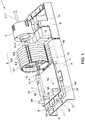
- Fig. 1 represents a first embodiment of the filter device 1 according to the invention for reducing electromagnetic interference with a modular assembly structure Fig. 1
- the filter device 1 is designed as an AC filter for alternating voltages.
- the filter device 1, as shown in Fig. 1 is shown, has a filter plate 2 for receiving first toroidal core holders 3. These toroidal core holders 3 can be pushed into guide rails of the filter plate 2 and contain a first number of ferrite rings. Insulated alternating current cables for different alternating current phases L and a neutral conductor N to form a current-compensated throttle of the filter device 1 are wound several times around the first toroidal core holder 3.
- the alternating current cables 4-L and the neutral conductor 4-N are connected, on the one hand, to connection contacts 5 of the filter device 1 and, on the other hand, passed through second toroidal core holders 6.
- the second toroidal core holders 6 are mounted on the filter plate 2 of the filter device 1 and have a second number of ferrite rings.
- the AC filter device 1 shown comprises a total of four lines, namely three AC cables 4-L1, 4-L2, 4-L3 for three different ones Current phases L1, L2, L3 and a neutral conductor 4-N.
- Fig. 1 only the winding of the alternating current cable 4-L1 for the first current phase L1 is shown.
- this alternating current cable 4-L and the neutral conductor 4-N can each be wound several times, for example three times, around the toroidal core holder 3 before they are passed through the second toroidal core holder 6.
- connection contacts 5 of the filter device 1 are provided on an end face of the filter plate 2.
- the connection contacts 5 each have a thread 5A which protrudes through a corresponding opening 7A of a first board 7.
- a cable lug 4A of an alternating current cable wound around the first toroidal core holder 3 or a neutral conductor is fastened to the thread 5A, which protrudes through the opening 7A of the first circuit board 7.
- the AC filter device 1 has four connection contacts 5 with four corresponding threads 5A, to which four cable lugs 4A for a neutral conductor 4-N and three AC cables 4-L can be connected.
- the first board 7 of the in Fig. 1 AC filter device 1 shown is equipped with electronic components 8, as in Fig. 2 recognizable. These components can in particular be capacitors and / or resistors.
- the components 8 are preferably attached to an assembly side of the first circuit board 7 which is opposite the filter plate 2 of the filter device 1, ie in Fig. 2 on the underside of the circuit board 7 shown there.
- the alternating current cables 4-L and the neutral conductor 4-N run along an in Fig. 2 back of the illustrated above first board 7 towards the threads 5A of the connection contacts 5 of the filter device 1 projecting through the opening 7A of the first board 7.
- the first board 7 has a front side that lies below and a rear side that lies above.
- the front of the first circuit board 7 forms the assembly side for the electronic components 8, in particular the capacitors provided there.
- the top rear of the first circuit board 7 is the side on which the alternating current cables 4-L and the neutral conductor 4-N run.
- a plastic cover for electrical insulation and for guiding and fastening the alternating current cables 4-L and the neutral conductor 4-N is provided on the back of the first circuit board 7. This can simplify assembly. In addition, the electrical insulation offers additional protection against short circuits.
- a second plate 9 is provided below the second toroidal core holder, as in FIG Fig. 2 shown.
- This second circuit board 9 is also equipped with electronic components 10. These electronic components 10 can also have capacitors.
- the second circuit board 9 can be inserted into the filter plate 2 of the filter device 1 and fastened there.
- the insulated alternating current cables 4 - L are enclosed by powder ring cores 19. These toroidal powder cores 19 can be located between the first toroidal core holders 3 and the second toroidal core holders 6.
- the on The capacitors 8, 10 provided on the two circuit boards 7, 9 of the filter device 1 have, in one possible embodiment, X capacitors for damping push-pull interference voltages and / or Y capacitors for suppressing interference voltages.
- the thread 5A protruding through the opening 7A of the first plate 7 is at least partially enclosed by a spacer sleeve on which the cable lug 4A of an alternating current cable 4-L or the neutral conductor 4-N is placed and releasably fastened by means of a nut. In this way, the assembly of the filter device 1 can be further facilitated.
- the illustrated embodiment of the filter device 1 is an AC filter device 1.
- the AC filter device 1 can be provided for supplying alternating current to a device through an alternating current network.
- This device can be an inverter, for example.
- the first toroidal core holders 3 contain a first number of ferrite rings.
- the second toroidal core holders 6 have a second number of ferrite rings.
- the first number of ferrite rings and / or the second number of ferrite rings is configurable. In this way, the filter device 1 according to the invention can be adapted in a simple manner for different applications. A reconfiguration of the filter device 1 for different applications is possible.
- the number of windings of the alternating current cables 4-L and of the neutral conductor 4-N around the first toroidal core holder 3 can also be configured. This offers a further degree of freedom for adapting the filter device 1 to the respective application.
- the toroidal core holders 3, 6 and the plates 7, 9 are interchangeably mounted on the filter plate 2 of the filter device 1. If, for example, a component of one of the filter boards 7, 9 is damaged, the board in question can be replaced in order to restore the functionality of the filter device 1.
- the electronic components 8, 10 with which the two circuit boards 7, 9 are fitted are detachably connected to the circuit boards 7, 9, in particular plugged in. In this embodiment it is possible to pull individual defective electronic components 8, 10 out of the circuit board 7, 9 and to replace them with a functional electronic component 8, 10. This allows the filter device 1 according to the invention to be repaired quickly and efficiently even if individual electronic components are damaged.
- the filter device 1 according to the invention allows a compact design to maintain air and creepage distances. It is not necessary to cast components for electrical insulation.
- the modular construction allows a quick and efficient assembly of the filter device 1 as well as an efficient and quick interchangeability of defective components.
- the modular assembly structure also leads to a relatively low weight of the filter device 1 according to the invention compared to conventional filter devices.
- a further advantage of the filter device 1 according to the invention is that the current-compensated throttle can be wound directly on the toroidal core holders 3 mounted on the mounting plate or filter plate 2, with no additional manufacturing aids being required. This leads to a further time savings when assembling the filter device 1 according to the invention.
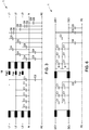
- FIG. 3 shows a circuit diagram of a possible embodiment of the AC filter device 1 according to the invention, the modular structure of which is shown in FIG Figures 1 , 2 is shown.
- the one in the Figure 3 The illustrated embodiment, the capacitors C1 to C6 are mounted on the circuit boards 7, 9.
- the capacitors C1, C4 are so-called X capacitors, which are provided for damping push-pull interference voltages and interference voltages between the supply lines.
- capacitors C2, C3, C5 and C6 are Y capacitors. These Y capacitors are intended to suppress interference voltages that occur on the same phase on the outer conductor and neutral conductor with respect to earth (common mode interference).
- the ring powder cores 19 can also be seen.
- AC filter device 1 shown has a power of 50 kW.
- the AC filter device 1 can also have an output of 100 kW, for example.
- the number of cores, turns and inductance can vary.
- the filter device 1 has a current-compensated throttle in which alternating current cables 4-L are wound around the toroidal cores contained in the first toroidal core holders 3.
- This current-compensated choke or common-mode choke CMC (English: common mode choke) has several windings that can flow in opposite directions to the working current, so that their magnetic fields cancel each other out in the core of the current-compensated choke.
- the current-compensated choke is used to attenuate interference emissions.
- the current-compensated choke suppresses asymmetrical (common mode) or common-mode interference currents that flow in the same direction on the supply lines. For the operating current that flows in push-pull, ie on lines in the opposite direction, the chokes represent only a low inductance. The magnetic fields of a push-pull current cancel each other out and consequently cannot generate a magnetic field in the ferrite core.
- the capacities of the X and Y capacitors can be adapted to the respective application.
- the X capacitor C1 has a capacitance of 3.3 microfarads and the X capacitor C4 has a capacitance of 6.8 microfarads.
- the Y capacitor C2 has a capacitance of 1 microfarad, for example, while the Y capacitor C3 has a capacitance of 100 nanofarads.
- the Y capacitor C5 can have a capacitance of 22 nanofarads, while the Y capacitor C6 only has a capacitance of 1 nanofarad.
- FIGS Figure 6 FIG. 4 shows a circuit diagram to illustrate a possible embodiment of the FIG Figures 4 , 5 shown filter device 1.
- the filter device 1 shown is a DC filter device.
- DC filter devices can be provided for direct current supply of a device, for example by a photovoltaic system or a photovoltaic module.
- the design of the DC filter device largely corresponds to the modular design of the AC filter device, although only two direct current cables are provided for opposing direct currents.
- the filter device 1 has only two connection contacts 5, namely a positive direct current connection DC + and a negative direct current connection DC-.
- the direct current cables for direct currents DC (4-DC) are also wound around the first toroidal core holder 3 and then passed through the second toroidal core holder 6.
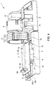
- the number of ferrite rings contained in the toroidal core holders is different from the number of ferrite rings in the AC filter device 1 as shown in FIG Figures 1 , 2 is shown. While the AC filter device 1 according to Fig. 1 in the illustrated embodiment has four first toroidal core holders 3-1,3-2,3-3,3-4, the DC filter device 1 according to FIG Fig. 5 only two toroidal core holders 3-1,3-2 Die Figure 6 FIG.
- FIG. 4 shows a circuit diagram for an implementation example of a DC filter device 1 according to the invention, the modular structure of which is shown in FIGS Figures 4 , 5 is shown.
- Fig. 6 shows a DC filter device 1 with an output of 50 kW or 100 kW, for example.
- the filter device 1 has capacitors C1, C2, C3 and discharge resistors R. These capacitors and discharge resistors can be provided as electronic components 8, 10 on the circuit boards 7, 9.
- the X capacitor C1 has a capacitance of 3.3 microfarads.
- the Y capacitors C2 have a capacitance of 1 microfarad, for example.
- the Y capacitors C3 have, for example, a capacitance of 2.2 nanofarads, while the Y capacitors C4 have a higher capacitance of 100 nanofarads.
- the discharge resistors R have a resistance value of 4.7 megohms, for example.
- the number of toroidal core holders 3 is, for example, two.
- the illustrated embodiment of the DC filter device 1 has a unit 17 for current measurement.
- One or both cables, ie one or both direct current cables, are passed through the current measuring unit 17.
- the capacitance of the capacitors with which the boards 7, 9 are equipped both in the AC filter device 1, as in the Figures 1 , 2 is shown, as well as in the DC filter device 1, as shown in FIGS Figures 4 , 5 shown vary.
- the electronic components 8, 10 on the circuit boards 7, 9 can be exchanged in order to optimize the filter device 1 for different applications.
- the electronic components 8, 10, ie the capacitors and / or the discharge resistors, are preferably plugged into corresponding plug-in devices so that they can be exchanged in a simple manner for repair purposes or for optimization purposes.
- a corresponding assembly of the circuit boards 7, 9 can take place in one possible variant before the final assembly of the filter device 1.
- the production of the filter device 1 can react flexibly to fluctuations with regard to the demand for different variants of the filter device 1.
- the various components in particular the toroidal core holders, can be used to manufacture both DC filter devices and AC filter devices.
- the assembly components of the circuit boards 7, 9, in particular the capacitors and resistors, can also be used to manufacture both DC filter devices and AC filter devices.
- the modular structure of the filter devices 1 thus enables a flexible use of stored electronic components for the production of different design variants of the filter devices 1.
- the assembly of a filter device 1 according to the invention can be carried out quickly and efficiently.
- the assembly of one of the Figures 1 , 2 AC filter device 1 shown step by step as follows.
- first toroidal core holders 3 are pushed one after the other onto a filter plate 2, which has corresponding guide rails.
- four toroidal core holders 3 are pushed one after the other into two parallel guide rails of the filter plate 2.
- a corresponding ferrite ring can be inserted into each toroidal core holder 3.
- Each toroidal core holder 3 can be pushed into the guide rails provided on the filter plate 2 on one side in the same orientation (plastic side first). Then a fixation can be done manually using a screw 11, as shown in the Figures 1 , 2 is shown.
- the connection contacts 5 can be attached to the filter plate 2. In this case, for example, each connection contact 5 can be fastened with the aid of two mounting screws.
- the first circuit board 7 is placed.
- the first circuit board 7 has openings 7A through which threads 5A of the connection contacts 5 are passed.
- a filter insulation or plastic cover can be used for electrical Insulation must be attached.
- the plastic cover is placed on the Figures 1 , 2 upwardly pointing back of the board 7 placed or placed.
- the attached plastic cover is in the Figures 1 , 2 not shown.
- the plastic cover can have guides that facilitate the assembly and laying of power cables.
- the attached plastic cover can also be fastened to the circuit board 7 with the aid of assembly elements, in particular screws.
- the circuit board 7 can be screwed on with the aid of four screws 12.
- spacer sleeves 13 are placed over the threaded heads 5A of the connection contacts 5, which partially enclose the threads 5A protruding through the openings 7A of the first board 7. These spacer sleeves 13 are in the Figures 1 , 2 shown.
- a so-called phase separator can be inserted into the cylindrical core of the toroidal core holder 3 in a next assembly step and brought into the correct orientation.
- the cable lug 4A of the first alternating current cable 4-L1 can be placed on the spacer sleeve 13 of a thread 5A of a corresponding connection contact 5.
- Each alternating current cable 4-L has an insulating hose which encloses the electrical line. For assembly, the insulation hose must not be pushed too far onto the cable lug 4A of the cable.
- the various AC cables 4-L1, 4-L2, 4-L3 are installed one after the other.
- the first alternating current cable 4-L1 for the first current phase L1 is wound around the first toroidal core holder 3 several times.
- the number of windings or turns can vary depending on the application.
- the one in the Figures 1 , 2 illustrated embodiment is the AC power cable 4-L1 wound three times around the four toroidal core holders 3 of the current-compensated choke.
- the second alternating current cable 4-L2 for the second alternating current phase L2 is then mounted in the same way by the alternating current cable 4-L2 also being wound three times around the four toroidal core holders 3 of the current-compensated choke.
- the third alternating current cable 4-L3 is wound around the four toroidal core holders 3 of the current-compensated choke.
- the neutral conductor N is then mounted by being connected to the corresponding connection contact 5 and also being repeatedly wound around the four toroidal core holders 3 of the current-compensated choke.
- the three alternating current cables 4-L1, 4-L2, 4-L3 and the neutral conductor 4-N mounted in this way preferably lie on the one in the Figures 1 , 2 insulating plastic cover, not shown.
- the plastic cover has guides for the various cables in which the cables can be hung. At least the slightly thinner neutral conductor 4-N can be mechanically attached to the plastic cover.
- the second circuit board 9, as shown in FIG Fig. 2 is shown, inserted into the filter plate 2 and fastened with the aid of four screws 15, for example.
- ring powder cores 19 can also be attached.
- three toroidal powder cores 19 are pushed onto the alternating current cables 4-L1, 4-L2, 4-L3 wound around the first toroidal core holder 3.
- the neutral conductor 4-N is not enclosed by any toroidal powder core 19.
- ferrite ring cores can be inserted into the second ring core holder 6.
- the alternating current lines 4-L1, 4-L2, 4-L3, which are each enclosed by a toroidal powder core 19, and the neutral conductor 4-N are passed through the inner cylindrical opening of the second toroidal core holder 6, as in FIG Figures 1 , 2 for the first power supply cable 4-L1.
- CMCs Common Mode Choke
- the second toroidal core holder 6 can be fixed to the mounting plate 2, for example with the aid of screws 14, as in FIG Fig. 1 recognizable.
- the second toroidal core holder 6 is thus above the components 10 of the second circuit board 9, as in FIG Figures 1 , 2 shown.
- star point lines can then be placed on the threads 5A of the connection contacts 5 and each fastened with a washer and a hexagon nut.
- the external thread 5A of the connection contact 5 is then enclosed with a spacer sleeve 13 in the cable lug 4A of a star point line, a washer and a hexagon nut located at the top.
- the hexagon nut is then tightened in a final assembly step. In this way, an assembly is created that is connected as a filter device 1 to other devices.
- the DC filter device 1 shown is carried out in an analogous manner.
- the fully assembled filter device 1 can also be dismantled again into its individual components in the reverse order of the assembly steps. In this way it is possible to recycle individual structural components of a filter device 1.
- the filter plate 2 of the filter device 1 serves as Carrier for mounting the assembly.
- the filter plate 2 is preferably made of a heat-dissipating material for cooling the assembly.
- the filter device 1 according to the invention can be configured or reconfigured for various application scenarios.
- the filter device 1 can also be used for currents with high current amplitudes.
- the modular design allows several levels to be used, so that the assembly according to the invention is compact and takes up little space within a device housing.
- the second toroidal core holder 6 is arranged above the second circuit board 9 equipped with components 10.
- the power cables run on the rear side of the first circuit board 7 above the components 8 which are attached to the front side of the circuit board 7.
- the current-carrying cables ie the alternating current cables 4-L and the direct current cables 4-DC as well as the neutral conductor 4-N, are flexible conductors that can be mounted directly on the first toroidal core holder 3, which is already inserted into the mounting plate or filter plate 2. In this way, a different winding can be made for a different number of winding turns during assembly, depending on the application. The orientation of the windings can also be changed depending on the application.
- the filter device 1 is not based on the Figures 1 to 6 illustrated embodiments limited.
- the number of current-carrying lines, in particular alternating current lines, can vary depending on the application.
Landscapes
- Engineering & Computer Science (AREA)
- Power Engineering (AREA)
- Coils Or Transformers For Communication (AREA)
- Filters And Equalizers (AREA)
- Centrifugal Separators (AREA)
- Surgical Instruments (AREA)
- Separation By Low-Temperature Treatments (AREA)
Abstract
Description
- Die Erfindung betrifft eine Filtervorrichtung, insbesondere eine Netzfiltervorrichtung zur Reduzierung elektromagnetischer Störungen mit einem modularen Montageaufbau.
- Netzfilter sind elektrische Schaltungen, die sowohl elektrische Störungen von elektrischen Geräten in einem Stromversorgungsnetz begrenzen als auch die elektromagnetische Verträglichkeit elektrischer Geräte gegenüber Störungen aus dem Stromversorgungsnetz erhöhen.
- Herkömmliche Netzfilter weisen meist eine fliegende Kontaktierung der Bauelemente bzw. Komponenten innerhalb des Filters auf. Zudem sind herkömmliche Filter mit einer höheren Leistung ab 50kW zur elektrischen Isolation meist vollständig vergossen. Dies erhöht einerseits das Gewicht und die Größe des Filters und minimiert andererseits die Leistungsklasse des Filters. Ein weiterer erheblicher Nachteil herkömmlicher Filter ist, dass das Aufbausystem bzw. die Montage derartiger Filter sehr zeitaufwendig ist. Weiterhin erlauben herkömmliche Netzfilter aufgrund der fliegenden Kontaktierung, bei dem die Bauteile verlötet werden oder das Filter vollständig vergossen wird, keinen Austausch von defekten Bauteilen. Eine Reparatur von derartigen herkömmlichen Filtervorrichtungen ist daher weitestgehend nicht möglich.
- Es ist daher eine Aufgabe der vorliegenden Erfindung, eine Filtervorrichtung zu schaffen, welche die oben genannten Nachteile vermeidet und insbesondere in einfacher und effizienter Weise innerhalb geringer Zeit montiert werden kann. Diese Aufgabe wird erfindungsgemäß durch eine Filtervorrichtung zur Reduzierung elektromagnetischer Störungen mit modularem Aufbau mit den in Patentanspruch 1 angegebenen Merkmalen gelöst.
- Die Erfindung schafft demnach eine Filtervorrichtung zur Reduzierung elektromagnetischer Störungen mit modularem Montageaufbau,
wobei die Filtervorrichtung ein Filterblech zur Aufnahme von ersten Ringkernhaltern aufweist, die in Führungsschienen des Filterblechs eingeschoben sind und eine erste Anzahl von Ferritringen enthalten, wobei um die ersten Ringkernhalter herum isolierte Wechselstromkabel für Wechselstromphasen und ein Neutralleiter oder isolierte Gleichstromkabel für Gleichströme zur Bildung einer stromkompensierten Drossel der Filtervorrichtung mehrfach gewickelt sind, wobei die Wechselstromkabel und der Neutralleiter oder die Gleichstromkabel einerseits mit Anschlusskontakten der Filtervorrichtung verbunden sind und andererseits durch zweite Ringkernhalter, die auf das Filterblech der Filtervorrichtung montiert sind und eine zweite Anzahl von Ferritringen enthalten, hindurchgeführt sind. - Ein Vorteil des modularen Aufbaus der erfindungsgemäßen Filtervorrichtung besteht darin, dass keine Bauelemente in eine Vergussmasse eingegossen werden müssen, um eine elektrische Isolation zu schaffen.
- Dies führt auch zu einer Gewichtsreduzierung und zu einer Verringerung der Größe der Filtervorrichtung gegenüber herkömmlichen Filtervorrichtungen.
- Ein weiterer Vorteil der erfindungsgemäßen Filtervorrichtung besteht darin, dass die Bauteile weitestgehend lösbare Verbindungen aufweisen, sodass einzelne Baukomponenten bei Auftreten eines Fehlers austauschbar sind. Weiterhin erlaubt der modulare Aufbau der Filtervorrichtung eine schnelle und effiziente Montage der Filtervorrichtung. Insbesondere ist es nicht notwendig, Bauteile miteinander zu verlöten.
- Bei einer möglichen Ausführungsform der erfindungsgemäßen Filtervorrichtung sind die Anschlusskontakte der Filtervorrichtung an einer Stirnseite des Filterblechs vorgesehen und weisen jeweils ein Gewinde auf, das durch eine entsprechende Öffnung einer ersten Platine hindurchragt, an dem ein Kabelschuh eines um die ersten Ringkernhalter herumgewickelten Wechsel- oder Gleichstromkabels befestigt ist.
- Bei einer weiteren möglichen Ausführungsform der erfindungsgemäßen Filtervorrichtung ist die erste Platine mit elektronischen Komponenten bestückt.
- Bei diesen elektrischen Komponenten kann es sich insbesondere um Kondensatoren oder Widerstände handeln.
- Bei einer weiteren möglichen Ausführungsform der erfindungsgemäßen Filtervorrichtung sind die Kondensatoren und/oder Widerstände auf einer Bestückungsseite der ersten Platine angebracht, die dem Filterblech der Filtervorrichtung gegenüberliegt.
- Bei einer möglichen Ausführungsform der erfindungsgemäßen Filtervorrichtung verlaufen die Wechsel- oder Gleichstromkabel entlang einer Rückseite der ersten Platine zu den durch die Öffnungen der ersten Platine hindurchragenden Gewinden der Anschlusskontakte der Filtervorrichtung.
- Bei einer weiteren möglichen Ausführungsform der erfindungsgemäßen Filtervorrichtung ist auf der Rückseite der ersten Platine eine Kunststoffabdeckung zur elektrischen Isolierung sowie zur Führung und Befestigung der Wechsel- oder Gleichstromkabel vorgesehen.
- Bei einer weiteren möglichen Ausführungsform der erfindungsgemäßen Filtervorrichtung ist unterhalb der zweiten Ringkernhalter eine zweite Platine vorgesehen, welche mit elektronischen Komponenten bestückt ist.
- Bei diesen elektronischen Komponenten kann es sich insbesondere auch um Kondensatoren handeln.
- Bei einer möglichen Ausführungsform der erfindungsgemäßen Filtervorrichtung ist die zweite Platine in das Filterblech der Filtervorrichtung eingelegt und dort befestigt.
- Bei einer weiteren möglichen Ausführungsform der erfindungsgemäßen Filtervorrichtung sind die isolierten Wechselstromkabel von Ringpulverkernen umschlossen.
- Bei einer möglichen Ausführungsform der erfindungsgemäßen Filtervorrichtung befinden sich die Ringpulverkerne zwischen den ersten Ringkernhaltern und den zweiten Ringkernhaltern.
- Bei einer weiteren möglichen Ausführungsform der erfindungsgemäßen Filtervorrichtung weisen die auf den beiden Platinen der Filtervorrichtung vorgesehenen Kondensatoren X-Kondensatoren zur Dämpfung von Gegentakt-Störspannungen und/oder Y-Kondensatoren zur Unterdrückung von Störspannungen auf.
- Bei einer weiteren möglichen Ausführungsform der erfindungsgemäßen Filtervorrichtung wird das durch die Öffnung der ersten Platine hindurchragende Gewinde teilweise von einer Distanzhülse umschlossen.
- Bei einer weiteren möglichen Ausführungsform der erfindungsgemäßen Filtervorrichtung wird auf das durch die Öffnung der ersten Platine hindurchragende Gewinde der Kabelschuh eines Wechselstromkabels oder eines Gleichstromkabels aufgesetzt und mittels einer Mutter lösbar befestigt.
- Bei einer weiteren möglichen Ausführungsform der erfindungsgemäßen Filtervorrichtung weist die Filtervorrichtung ein PV-Generator-seitiges DC-Filter zur Filterung der Gleichstromversorgung eines Gerätes durch einen Photovoltaikgenerator auf.
- Bei einer weiteren möglichen Ausführungsform der erfindungsgemäßen Filtervorrichtung weist die Filtervorrichtung ein netzseitiges AC-Filter zur Filterung der Wechselstromversorgung eines Gerätes durch ein Wechselstromnetz auf.
- Bei einer weiteren möglichen Ausführungsform der erfindungsgemäßen Filtervorrichtung ist die Filtervorrichtung ein netzseitiges AC-Filter zur Filterung der Wechselstromversorgung eines Wechselrichters.
- Bei einer weiteren möglichen Ausführungsform der erfindungsgemäßen Filtervorrichtung ist die erste Anzahl von Ferritringen und/oder die zweite Anzahl von Ferritringen konfigurierbar.
- Bei einer weiteren möglichen Ausführungsform der erfindungsgemäßen Filtervorrichtung ist die Anzahl von Wicklungen der Wechselstromkabel oder der Gleichstromkabel um die ersten Ringkernhalter herum konfigurierbar.
- Bei einer weiteren möglichen Ausführungsform der erfindungsgemäßen Filtervorrichtung sind die Ringkernhalter und/oder die Platinen austauschbar an dem Filterblech der Filtervorrichtung montiert.
- Im Weiteren werden mögliche Ausführungsformen der erfindungsgemäßen Filtervorrichtung unter Bezugnahme auf die beigefügten Figuren näher erläutert.
-
- Fig. 1
- eine perspektivische Seitenansicht auf eine erste mögliche Ausführungsform der erfindungsgemäßen Filtervorrichtung;
- Fig. 2
- eine weitere perspektivische Seitenansicht auf das in
Fig. 1 dargestellte Filter ohne das Filterblech; - Figur 3
- ein Schaltkreisdiagram für ein mögliches Ausführungsbeispiel der in den
Figuren 1 ,2 dargestellten Filtervorrichtung; - Fig. 4
- eine perspektivische Seitenansicht auf eine zweite Ausführungsform der erfindungsgemäßen Filtervorrichtung;
- Fig. 5
- eine weitere perspektivische Seitenansicht auf der in
Fig. 4 dargestellten Filtervorrichtung ohne Filterblech; - Figur 6
- ein Schaltkreisdiagram möglicher Ausführungsbeispiele der in den
Figuren 4 ,5 dargestellten Filtervorrichtung. -
Fig. 1 stellt eine erste Ausführungsform der erfindungsgemäßen Filtervorrichtung 1 zur Reduzierung elektromagnetischer Störungen mit modularem Montageaufbau dar. Bei der inFig. 1 dargestellten Ausführungsform ist die Filtervorrichtung 1 als AC-Filter für Wechselspannungen ausgelegt. Die Filtervorrichtung 1, wie sie inFig. 1 dargestellt ist, weist ein Filterblech 2 zur Aufnahme von ersten Ringkernhaltern 3 auf. Diese Ringkernhalter 3 können in Führungsschienen des Filterblechs 2 eingeschoben werden und eine erste Anzahl von Ferritringen enthalten. Um die ersten Ringkernhalter 3 herum sind isolierte Wechselstromkabel für verschiedene Wechselstromphasen L sowie ein Neutraleiter N zur Bildung einer stromkompensierten Drossel der Filtervorrichtung 1 mehrfach gewickelt. Die Wechselstromkabel 4-L und der Neutralleiter 4-N sind einerseits mit Anschlusskontakten 5 der Filtervorrichtung 1 verbunden und andererseits durch zweite Ringkernhalter 6 hindurchgeführt. Die zweiten Ringkernhalter 6 sind auf das Filterblech 2 der Filtervorrichtung 1 montiert und weisen eine zweite Anzahl von Ferritringen auf. Die inFig. 1 dargestellte AC-Filtervorrichtung 1 umfasst insgesamt vier Leitungen, nämlich drei Wechselstromkabel 4-L1, 4-L2, 4-L3 für drei verschiedenen Stromphasen L1, L2, L3 sowie einen Neutralleiter 4-N. InFig. 1 ist lediglich die Wicklung des Wechselstromkabels 4-L1 für die erste Stromphase L1 dargestellt. Bei dem inFig. 1 dargestellten Ausführungsbeispiel der AC-Filtervorrichtung 1 kann dieses Wechselstromkabel 4-L und der Neutralleiterleiter 4-N jeweils mehrfach, beispielsweise dreimal, um die Ringkernhalter 3 herumgewickelt werden, bevor sie durch den zweiten Ringkernhalter 6 hindurchgeführt werden. - Wie in den
Figuren 1 ,2 erkennbar, sind die Anschlusskontakte 5 der Filtervorrichtung 1 an einer Stirnseite des Filterblechs 2 vorgesehen. Die Anschlusskontakte 5 weisen jeweils ein Gewinde 5A auf, das durch eine entsprechende Öffnung 7A einer ersten Platine 7 hindurchragt. An dem Gewinde 5A, welches durch die Öffnung 7A der ersten Platine 7 hindurchragt, ist ein Kabelschuh 4A eines um die ersten Ringkernhalter 3 herumgewickelten Wechselstromkabels oder eines Neutralleiterleiters befestigt. Bei dem inFig. 1 dargestellten Ausführungsbeispiel weist die AC-Filtervorrichtung 1 vier Anschlusskontakte 5 mit vier entsprechenden Gewinden 5A auf, an denen vier Kabelschuhe 4A für einen Neutralleiterleiter 4-N und drei Wechselstromkabel 4-L angeschlossen werden können. - Die erste Platine 7 der in
Fig. 1 dargestellten AC-Filtervorrichtung 1 ist mit elektronischen Komponenten 8 bestückt, wie inFig. 2 erkennbar. Bei diesen Komponenten kann es sich insbesondere um Kondensatoren und/oder Widerständehandeln. Die Komponenten 8 sind dabei vorzugsweise auf einer Bestückungsseite der ersten Platine 7 angebracht, die dem Filterblech 2 der Filtervorrichtung 1 gegenüberliegt, d.h. inFig. 2 auf der Unterseite der dort dargestellten Platine 7. Die Wechselstromkabel 4-L sowie der Neutralleiter 4-N verlaufen entlang einer inFig. 2 oben dargestellten Rückseite der ersten Platine 7 hin zu den durch die Öffnung 7A der ersten Platine 7 hindurchragenden Gewinden 5A der Anschlusskontakte 5 der Filtervorrichtung 1. In der Darstellung gemäßFig. 1 ,2 weist die erste Platine 7 eine Vorderseite auf, die unten liegt und eine Rückseite, die oben liegt. Die Vorderseite der ersten Platine 7 bildet die Bestückungsseite für die elektronischen Komponenten 8, insbesondere die dort vorgesehenen Kondensatoren. Die oben liegende Rückseite der ersten Platine 7 ist diejenige Seite, auf welcher die Wechselstromkabel 4-L und der Neutralleiter 4-N verlaufen. - Bei einer bevorzugten Ausführungsform der erfindungsgemäßen Filtervorrichtung 1 ist auf der Rückseite der ersten Platine 7 eine Kunststoffabdeckung zur elektrischen Isolierung sowie zur Führung und Befestigung der Wechselstromkabel 4-L und des Neutralleiters 4-N vorgesehen. Hierdurch kann die Montage vereinfacht werden. Darüber hinaus bietet die elektrische Isolierung eine zusätzliche Absicherung gegenüber Kurzschlüssen.
- Bei einer weiteren möglichen Ausführungsform ist unterhalb der zweiten Ringkernhalter eine zweite Platine 9 vorgesehen, wie in
Fig. 2 dargestellt. Diese zweite Platine 9 ist ebenfalls mit elektronischen Komponenten 10 bestückt. Diese elektronischen Komponenten 10 können ebenfalls Kondensatoren aufweisen. Die zweite Platine 9 kann in das Filterblech 2 der Filtervorrichtung 1 eingelegt werden und dort befestigt werden. - Bei einer möglichen Ausführungsform sind die isolierten Wechselstromkabel 4-L von Ringpulverkernen 19 umschlossen. Diese Ringpulverkerne 19 können sich zwischen den ersten Ringkernhaltern 3 und den zweiten Ringkernhaltern 6 befinden. Die auf den beiden Platinen 7, 9 der Filtervorrichtung 1 vorgesehenen Kondensatoren 8, 10 weisen bei einer möglichen Ausführungsform X-Kondensatoren zur Dämpfung von Gegentakt-Störspannungen und/oder Y-Kondensatoren zur Unterdrückung von Störspannungen auf. Bei einer möglichen Ausführungsform wird das durch die Öffnung 7A der ersten Platine 7 hindurchragende Gewinde 5A zumindest teilweise von einer Distanzhülse umschlossen, auf die der Kabelschuh 4A eines Wechselstromkabels 4-L oder des Neutralleiters 4-N aufgesetzt und mittels einer Mutter lösbar befestigt ist. Hierdurch kann die Montage der Filtervorrichtung 1 weiter erleichtert werden.
- Die in
Fig. 2 dargestellte Ausführungsform der Filtervorrichtung 1 stellt eine AC-Filtervorrichtung 1 dar. Die AC-Filtervorrichtung 1 kann zur Wechselstromversorgung eines Gerätes durch ein Wechselstromnetz vorgesehen sein. Bei diesem Gerät kann es sich beispielsweise um einen Wechselrichter handeln. Die ersten Ringkernhalter 3 enthalten eine erste Anzahl von Ferritringen. Die zweiten Ringkernhalter 6 weisen eine zweite Anzahl von Ferritringen auf. Bei einer möglichen Ausführungsform ist die erste Anzahl von Ferritringen und/oder die zweite Anzahl von Ferritringen konfigurierbar. Hierdurch kann die erfindungsgemäße Filtervorrichtung 1 für verschiedene Anwendungsfälle in einfacher Weise angepasst werden. Eine Umkonfigurierung der Filtervorrichtung 1 für verschiedene Anwendungsfälle ist möglich. - Bei einer weiteren möglichen Ausführungsform der erfindungsgemäßen Filtervorrichtung 1 ist die Anzahl von Wicklungen der Wechselstromkabel 4-L und des Neutralleiters 4-N um die ersten Ringkernhalter 3 herum ebenfalls konfigurierbar. Dies bietet einen weiteren Freiheitsgrad zur Anpassung der Filtervorrichtung 1 an den jeweiligen Anwendungsfall.
- Weiterhin sind die Ringkernhalter 3, 6 und die Platinen 7, 9 bei einer möglichen Ausführungsform an dem Filterblech 2 der Filtervorrichtung 1 austauschbar montiert. Ist beispielsweise eine Komponente einer der Filterplatinen 7, 9 beschädigt, kann die betreffende Platine ausgetauscht werden, um die Funktionsfähigkeit der Filtervorrichtung 1 wiederherzustellen. Bei einer möglichen Ausführungsform sind die elektronischen Komponenten 8, 10, mit welchen die beiden Platinen 7, 9 bestückt sind, lösbar mit den Platinen 7, 9 verbunden, insbesondere eingesteckt. Bei dieser Ausführungsform ist es möglich, einzelne fehlerhafte elektronische Komponenten 8, 10 aus der Platine 7, 9 herauszuziehen und durch eine funktionsfähige elektronische Komponente 8, 10 zu ersetzen. Dies erlaubt es, die erfindungsgemäße Filtervorrichtung 1 selbst bei Beschädigung einzelner elektronischer Komponenten schnell und effizient zu reparieren.
- Die erfindungsgemäße Filtervorrichtung 1, wie sie in den Figuren 1, 2 dargestellt ist, erlaubt eine kompakte Bauweise zur Einhaltung von Luft- und Kriechstrecken. Ein Verguss von Bauelementen zur elektrischen Isolation ist nicht erforderlich. Die modulare Bauweise erlaubt eine schnelle und effiziente Montage der Filtervorrichtung 1 sowie eine effiziente und schnelle Austauschbarkeit von fehlerhaften Komponenten. Der modulare Montageaufbau führt darüber hinaus zu einem relativ geringen Gewicht der erfindungsgemäßen Filtervorrichtung 1 im Vergleich zu herkömmlichen Filtervorrichtungen. Ein weiterer Vorteil der erfindungsgemäßen Filtervorrichtung 1 besteht darin, dass die stromkompensierte Drossel direkt an den am das Montageblech bzw. Filterblech 2 montierten Ringkernhaltern 3 gewickelt werden kann, wobei keine zusätzlichen Fertigungshilfsmittel erforderlich sind. Dies führt zu einer weiteren Zeitersparnis bei der Montage der erfindungsgemäßen Filtervorrichtung 1.
-
Figur 3 zeigt ein Schaltkreisdiagram eines möglichen Ausführungsbeispiels der erfindungsgemäßen AC-Filtervorrichtung 1, deren modularer Aufbau in denFiguren 1 ,2 dargestellt ist. Bei dem in derFigur 3 dargestellten Ausführungsbeispiel sind die Kondensatoren C1 bis C6 auf den Platinen 7, 9 montiert. Bei den Kondensatoren C1, C4 handelt es sich um sogenannte X-Kondensatoren, die zur Dämpfung von Gegentakt-Störspannungen und Störspannungen zwischen den Zuleitungen vorgesehen sind. Demgegenüber sind die Kondensatoren C2, C3, C5 und C6 Y-Kondensatoren. Diese Y-Kondensatoren sind zur Unterdrückung von Störspannungen, die auf der gleichen Phase auf Außenleiter und Neutralleiter gegenüber Erde auftreten (Gleichtaktstörungen), vorgesehen. - In der
Figur 3 sind zudem die Ringpulverkerne 19 (Fep) erkennbar. Die inFig. 3 dargestellte AC-Filtervorrichtung 1 hat eine Leistung von 50 kW. Die AC-Filtervorrichtung 1 kann auch beispielsweise eine Leistung von 100 kW aufweisen. Die Anzahl der Kerne, Windungen und Induktivität kann variieren. Beispielsweise weist die Implementierung gemäßFig. 3 drei Kerne mit fünf Windungen und einer Induktivität von L = 500 Mikrohenry auf. Bei einer AC-Filtervorrichtung 1 mit einer Leistung von 100 kW beträgt die Anzahl der Kerne vier und die Anzahl der Windungen ebenfalls vier und die Induktivität L = 450 Mikrohenry. - Die erfindungsgemäße Filtervorrichtung 1 besitzt eine stromkompensierte Drossel, bei der Wechselstromkabel 4-L um die in den ersten Ringkernhaltern 3 enthaltenen Ringkerne herumgewickelt sind. Diese stromkompensierte Drossel bzw. Gleichtaktdrossel CMC(englisch: common mode choke) besitzt mehrere Wicklungen, die gegensinnig zum Arbeitsstrom durchflossen werden können, sodass sich deren magnetische Felder im Kern der stromkompensierten Drossel aufheben. Die stromkompensierte Drossel wird zur Dämpfung von Störemissionen verwendet. Die stromkompensierte Drossel unterdrückt asymmetrische (common mode) oder Gleichtaktstörströme, die in gleicher Richtung auf den Zuleitungen fließen. Für den Betriebsstrom, der im Gegentakt, d.h. auf Leitungen entgegengesetzter Richtung, fließt, stellen die Drosseln dagegen nur eine geringe Induktivität dar. Die Magnetfelder eines Gegentaktstromes heben sich auf und können folglich auch kein Magnetfeld im Ferritkern erzeugen.
- Die Kapazitäten der X- und Y-Kondensatoren können an den jeweiligen Anwendungsfall angepasst werden. Bei dem in der Figur 3 dargestellten Ausführungsbeispiel weist der X-Kondensator C1 eine Kapazität von 3,3 Mikrofarad und der X-Kondensator C4 eine Kapazität von 6,8 Mikrofarad auf. Der Y-Kondensator C2 weist beispielsweise eine Kapazität von 1 Mikrofarad auf, während der Y-Kondensator C3 eine Kapazität von 100 Nanofarad besitzt. Weiterhin kann der Y-Kondensator C5 eine Kapazität von 22 Nanofarad aufweisen, während der Y-Kondensator C6 lediglich eine Kapazität von 1 Nanofarad besitzt.
- Die
Figuren 4 und5 zeigen eine weitere Ausführungsform der erfindungsgemäßen Filtervorrichtung 1. DieFiguren 4 ,5 zeigen den modularen und Hardware-Aufbau bei dieser Ausführungsform der Filtervorrichtung 1. DieFigur 6 zeigt ein Schaltkreisdiagramm zur Darstellung eines möglichen Ausführungsbeispiels der in denFiguren 4 ,5 dargestellten Filtervorrichtung 1. Die in denFiguren 4 bis 6 dargestellte Filtervorrichtung 1 ist eine DC-Filtervorrichtung. DC-Filtervorrichtungen können für eine Gleichstromversorgung eines Gerätes, beispielsweise durch eine Photovoltaikanlage oder ein Photovoltaikmodul vorgesehen sein. Der Aufbau der DC-Filtervorrichtung entspricht weitestgehend dem modularen Aufbau der AC-Filtervorrichtung, wobei allerdings lediglich zwei Gleichstromkabel für entgegengesetzte Gleichströme vorgesehen sind. Dementsprechend weist die Filtervorrichtung 1 nur zwei Anschlusskontakte 5 auf, nämlich einen positiven Gleichstromanschluss DC+ und einen negativen Gleichstromanschluss DC-. Die Gleichstromkabel für Gleichströme DC (4-DC) werden ebenfalls um den ersten Ringkernhalter 3 herumgewickelt und anschließend durch zweite Ringkernhalter 6 hindurchgeführt. Die Anzahl der in den Ringkernhaltern enthaltenen Ferritringe ist unterschiedlich zu der Anzahl der Ferritringen bei der AC-Filtervorrichtung 1, wie sie in denFiguren 1 ,2 dargestellt ist. Während die AC-Filtervorrichtung 1 gemäßFig. 1 in dem dargestellten Ausführungsbeispiel vier erste Ringkernhalter 3-1,3-2,3-3,3-4aufweist, besitzt die DC-Filtervorrichtung 1 gemäßFig. 5 lediglich zwei Ringkernhalter 3-1,3-2 DieFigur 6 zeigt ein Schaltkreisdiagramm für ein Implementierungsbeispiel einer erfindungsgemäßen DC-Filtervorrichtung 1, deren modularer Aufbau in denFiguren 4 ,5 dargestellt ist.Fig. 6 zeigt eine DC-Filtervorrichtung 1 mit einer Leistung von beispielsweise 50 kW oder 100 kW. Die Filtervorrichtung 1 besitzt Kondensatoren C1, C2, C3 und Entladewiderstände R. Diese Kondensatoren und Entladewiderstände können als elektronische Komponenten 8, 10 auf den Platinen 7, 9 vorgesehen sein. Bei einer möglichen Implementierung weist der X-Kondensator C1 eine Kapazität von 3,3 Mikrofarad auf. Die Y-Kondensatoren C2 besitzen beispielsweise eine Kapazität von 1 Mikrofarad. Die Y-Kondensatoren C3 weisen beispielsweise eine Kapazität von 2,2 Nanofarad auf, während die Y-Kondensatoren C4 eine höhere Kapazität von 100 Nanofarad besitzen. Die Entladewiderstände R weisen beispielsweise einen Widerstandswert von 4,7 Megaohm auf. Wie in denFiguren 4 ,5 erkennbar, ist die Anzahl der Ringkernhalter 3 beispielsweise zwei. Die Anzahl der Windungen bzw. Wicklungen der Gleichstromkabel beträgt beispielsweise N = 5. Weiterhin kann die Induktivität L = 300 Mikrohenry sein. - Die in den
Figuren 4 ,5 dargestellte Ausführungsform der DC-Filtervorrichtung 1 weist eine Einheit 17 zur Strommessung auf. Durch die Stromesseinheit 17 werden eines oderbeide Kabel, d.h. eines oder beide Gleichstromkabel, geführt. - Je nach Anwendungsfall kann die Kapazität der Kondensatoren, mit welchen die Platinen 7, 9 bestückt sind, sowohl bei der AC-Filtervorrichtung 1, wie sie in den
Figuren 1 ,2 dargestellt ist, als auch in der DC-Filtervorrichtung 1, wie sie in denFiguren 4 ,5 dargestellt ist, variieren. Bei einer bevorzugten Ausführungsform können die elektronischen Komponenten 8, 10 an den Platinen 7, 9 ausgetauscht werden, um die Filtervorrichtung 1 für verschiedene Anwendungsfälle zu optimieren. Vorzugsweisesind die elektronischen Komponenten 8, 10, d.h. die Kondensatoren und/oder die Entladewiderstände, in entsprechende Steckeinrichtungen eingesteckt, sodass sie einfacher Weise zu Reparaturzwecken oder Optimierungszwecken ausgetauscht werden können. Eine entsprechende Bestückung der Platinen 7, 9 kann in einer möglichen Variante vor der Endmontage der Filtervorrichtung 1 erfolgen. Hierdurch kann die Produktion der Filtervorrichtung 1 flexibel auf Schwankungen hinsichtlich der Nachfrage von unterschiedlichen Varianten der Filtervorrichtung 1 reagieren. - Die verschiedenen Komponenten, insbesondere die Ringkernhalter, können zur Fertigung sowohl von DC-Filtervorrichtungen als auch AC-Filtervorrichtungen verwendet werden. Auch die Bestückungskomponenten der Platinen 7, 9, insbesondere die Kondensatoren und Widerstände, können zur Fertigung sowohl von DC-Filtervorrichtungen als auch AC-Filtervorrichtungen verwendet werden. Der modulare Aufbau der Filtervorrichtungen 1 ermöglicht somit eine flexible Verwendung von gelagerten elektronischen Komponenten zur Herstellung unterschiedlicher Ausführungsvarianten der Filtervorrichtungen 1.
- Die Montage einer erfindungsgemäßen Filtervorrichtung 1 kann schnell und effizient durchgeführt werden. Beispielsweise kann die Montage einer der in den
Figuren 1 ,2 dargestellten AC-Filtervorrichtung 1 wie folgt schrittweise erfolgen. In einem ersten Montageschritt werden auf ein Filterblech 2, welches über entsprechende Führungsschienen verfügt, erste Ringkernhalter 3 nacheinander eingeschoben. Beispielsweise werden nacheinander vier Ringkernhalter 3 in zwei parallel verlaufende Führungsschienen des Filterbleches 2 eingeschoben. Hierzu weisen die vier Ringkernhalter 3 der AC-Filtervorrichtung 1, wie inFig. 2 dargestellt, an der Unterseite entsprechende Führungseinrichtungen 16 auf, die es erlauben, die Ringkernhalter 3 in Führungsschienen des Filterbleches 2 in einfacher Weise mechanisch einzuschieben. In jeden Ringkernhalter 3 kann ein entsprechender Ferritring eingelegt werden. Jeder Ringkernhalter 3 kann in gleicher Orientierung (Kunststoffseite voran) auf einer Seite in die vorgesehenen Führungsschienen des Filterblechs 2 eingeschoben werden. Anschließend kann eine Fixierung mithilfe einer Schraube 11 manuell erfolgen, wie sie in denFiguren 1 ,2 dargestellt ist. In einem weiteren Schritt können die Anschlusskontakte 5 an das Filterblech 2 angebracht werden. Dabei kann beispielsweise jeder Anschlusskontakt 5 mithilfe von zwei Montageschrauben befestigt werden. Nach Anbringung der Anschlusskontakte 5 auf dem Filterblech 2 wird die erste Platine 7 aufgelegt. Die erste Platine 7 weist Öffnungen 7A auf, durch welche hindurch Gewinde 5A der Anschlusskontakte 5 hindurchgeführt werden. In einem weiteren Montageschritt kann eine Filterisolierung bzw. Kunststoffabdeckung zur elektrischen Isolierung angebracht werden. Hierzu wird die Kunststoffabdeckung auf der in denFiguren 1 ,2 nach oben zeigenden Rückseite der Platine 7 aufgesetzt bzw. aufgelegt. Die aufgesetzte Kunststoffabdeckung ist in denFiguren 1 ,2 nicht dargestellt. Die Kunststoffabdeckung kann Führungen aufweisen, welche die Montage und Verlegung von Stromkabeln erleichtern. Die aufgesetzte Kunststoffabdeckung kann ebenfalls mithilfe von Montageelementen, insbesondere Schrauben, an die Platine 7 befestigt werden. Beispielsweise kann die Platine 7 mithilfe von vier Schrauben 12 angeschraubt werden. In einem weiteren Montageschritt werden Distanzhülsen 13 über die Gewindeköpfe 5A der Anschlusskontakte 5 aufgesetzt, welche die durch die Öffnungen 7A der ersten Platine 7 hindurchragenden Gewinde 5A teilweise umschließen. Diese Distanzhülsen 13 sind in denFiguren 1 ,2 dargestellt. - Bei einer möglichen Ausführungsvariante kann in einem nächsten Montageschritt ein sogenannter Phasentrenner in den zylindrischen Kern der Ringkernhalter 3 eingesetzt werden und in die richtige Orientierung verbracht werden. Nach Anbringen des Phasentrenners kann der Kabelschuh 4A des ersten Wechselstromkabels 4-L1 auf die Distanzhülse 13 eines Gewindes 5A eines entsprechenden Anschlusskontaktes 5 aufgesetzt werden. Jedes Wechselstromkabel 4-L weist einen Isolationsschlauch auf, welcher die elektrische Leitung umhüllt. Zur Montage darf der Isolationsschlauch nicht zu weit auf den Kabelschuh 4A des Kabels geschoben werden. Die verschiedenen Wechselstromkabel 4-L1, 4-L2, 4-L3 werden nacheinander montiert. Zunächst wird das erste Wechselstromkabel 4-L1 für die erste Stromphase L1 um die ersten Ringkernhalter 3 herum mehrfach gewickelt. Die Anzahl der Wicklungen bzw. Windungen kann je nach Anwendungsfall variieren. Bei dem in den
Figuren 1 ,2 dargestellten Ausführungsbeispiel wird das Wechselstromkabel 4-L1 dreimal um die vier Ringkernhalter 3 der stromkompensierten Drossel gewickelt. In einem weiteren Montageschritt wird anschließend das zweite Wechselstromkabel 4-L2 für die zweite Wechselstromphase L2 in gleicher Weise montiert, indem das Wechselstromkabel 4-L2 ebenfalls dreimal um die vier Ringkernhalter 3 der stromkompensierten Drossel herumgewickelt wird. Anschließend wird in einem weiteren Montageschritt das dritte Wechselstromkabel 4-L3 um die vier Ringkernhalter 3 der stromkompensierten Drossel herumgewickelt. In einem weiteren Montageschritt wird anschließend der Neutralleiter N montiert, indem er an dem entsprechenden Anschlusskontakt 5 angeschlossen wird und ebenfalls mehrfach um die vier Ringkernhalter 3 der stromkompensierten Drossel herumgewickelt wird. Die in dieser Weise montierten drei Wechselstromkabel 4-L1, 4-L2, 4-L3 und der Neutralleiter 4-N liegen dabei vorzugsweise auf der in denFiguren 1 ,2 nicht dargestellten isolierenden Kunststoffabdeckung auf. Die Kunststoffabdeckung besitzt Führungen für die verschiedenen Kabel, in welche die Kabel eingehängt werden können. Zumindest der etwas dünnere Neutralleiter 4-N kann mechanisch an der Kunststoffabdeckung eingehängt werden. - In einem weiteren Montageschritt wird die zweite Platine 9, wie sie in
Fig. 2 dargestellt ist, in das Filterblech 2 eingelegt und beispielsweise mithilfe von vier Schrauben 15 befestigt. - In einem weiteren Montageschritt können zudem Ringpulverkerne 19 angebracht werden. Hierzu werden beispielsweise drei Ringpulverkerne 19 auf die um die ersten Ringkernhalter 3 herumgewickelten Wechselstromkabel 4-L1, 4-L2, 4-L3 aufgeschoben. Der Neutralleiter 4-N wird von keinem Ringpulverkern 19 umschlossen.
- In einem weiteren Montageschritt können Ferritringkerne in den zweiten Ringkernhalter 6 eingesetzt bzw. eingelegt werden. In einem weiteren Montageschritt werden die Wechselstromleitungen 4-L1, 4-L2, 4-L3, welche jeweils durch einen Ringpulverkern 19 umschlossen sind, sowie der Neutralleiter 4-N durch die innere zylindrische Öffnung der zweiten Ringkernhalter 6 hindurchgeführt, wie in den
Figuren 1 ,2 für das erste Stromversorgungskabel 4-L1 dargestellt. Auf diese Weise werden CMCs (Common Mode Choke)gebildet. In einem weiteren Montageschritt können die zweiten Ringkernhalter 6 an dem Montageblech 2 fixiert werden, beispielsweise mithilfe von Schrauben 14, wie inFig. 1 erkennbar. Der zweite Ringkernhalter 6 liegt somit oberhalb der Komponenten 10 der zweiten Platine 9, wie in denFiguren 1 ,2 dargestellt. Bei einer möglichen Ausführungsform können anschließend an den Gewinden 5A der Anschlusskontakte 5 Sternpunktleitungen aufgelegt werden und jeweils mit einer Beilagscheibe und einer Sechskantmutter befestigt werden. Von unten nach oben ist das Außengewinde 5A des Anschlusskontaktes 5 dann mit einer Distanzhülse 13 im Kabelschuh 4A einer Sternpunktleitung, einer Beilagscheibe und einer oben liegenden Sechskantmutter umschlossen. Die Sechskantmutter wird anschließend in einem finalen Montageschritt festgezogen. Auf diese Weise entsteht eine Baugruppe, die als Filtervorrichtung 1 mit weiteren Geräten verbunden werden. Die Montage der in denFiguren 4 ,5 dargestellten DC-Filtervorrichtung 1 erfolgt in analoger Weise. - Die fertig montierte Filtervorrichtung 1 kann in umgekehrter Reihenfolge der Montageschritte auch wieder in ihre Einzelbestandteile zerlegt werden. Auf diese Weise ist es möglich, einzelne Baukomponenten einer Filtervorrichtung 1 zu recyceln. Das Filterblech 2 der Filtervorrichtung 1 dient als Träger zur Montage der Baugruppe. Das Filterblech 2 besteht vorzugsweise aus einem wärmeableitenden Material zur Kühlung der Baugruppe. Die erfindungsgemäße Filtervorrichtung 1 kann für verschiedene Anwendungsszenarien konfiguriert bzw. umkonfiguriert werden. Dabei kann die Filtervorrichtung 1 auch für Ströme mit hohen Stromamplitudeneingesetzt werden. Bei der erfindungsgemäßen Filtervorrichtung 1 erlaubt die modulare Bauweise, mehrere Ebenen auszunutzen, sodass die erfindungsgemäße Baugruppe kompakt ist und innerhalb eines Gerätegehäuses wenig Platz einnimmt. Beispielsweise ist der zweite Ringkernhalter 6 oberhalb der mit Komponenten 10 bestückten zweiten Platine 9 angeordnet. Weiterhin verlaufen die Stromkabel auf der Rückseite der ersten Platine 7 oberhalb der Komponenten 8, die auf der Vorderseite der Platine 7 angebracht sind. Die stromführenden Kabel, d.h. die Wechselstromkabel 4-L und die Gleichstromkabel 4-DC sowie der Neutralleiter 4-N, sind flexible Leiter, die direkt auf die ersten Ringkernhalter 3 montiert werden können, welche bereits in das Montageblech bzw. Filterblech 2 eingeschoben sind. Damit kann während der laufenden Montage eine unterschiedliche Wicklung für eine unterschiedliche Anzahl der Wicklungswindungen erfolgen, je nach Anwendungsfall. Auch die Orientierung der Wicklungen kann je nach Anwendungsfall geändert werden.
- Die erfindungsgemäße Filtervorrichtung 1 ist nicht auf die in den
Figuren 1 bis 6 dargestellten Ausführungsbeispiele beschränkt. Beispielsweise kann die Anzahl der stromführenden Leitungen, insbesondere Wechselstromleitungen, je nach Anwendungsfall variieren.
Claims (15)
- Filtervorrichtung (1) zur Reduzierung elektromagnetischer Störungen mit modularem Montageaufbau,
wobei die Filtervorrichtung (1) ein Filterblech (2) zur Aufnahme von ersten Ringkernhaltern (3) aufweist, die in Führungsschienen des Filterblechs (2) eingeschoben sind und eine erste Anzahl von Ferritringen enthalten, wobei um die ersten Ringkernhalter (3) herum isolierte Wechselstromkabel (4-L) für Wechselstromphasen (L) und ein Neutralleiter (4-N) oder isolierte Gleichstromkabel (4-DC) für Gleichströme (DC) zur Bildung einer stromkompensierten Drossel der Filtervorrichtung (1) mehrfach gewickelt sind, wobei die Wechselstromkabel (4-L) und der Neutralleiter (4-N) oder die Gleichstromkabel (4-DC) einerseits mit Anschlusskontakten (5) der Filtervorrichtung (1) verbunden sind und andererseits durch zweite Ringkernhalter (6), die auf das Filterblech (2) der Filtervorrichtung (1) montiert sind und eine zweite Anzahl von Ferritringen enthalten, hindurchgeführt sind. - Filtervorrichtung nach Anspruch 1,
wobei die Anschlusskontakte (5) der Filtervorrichtung (1) an einer Stirnseite des Filterblechs (2) vorgesehen sind und jeweils ein Gewinde (5A) aufweisen, das durch eine entsprechende Öffnung (7A) einer ersten Platine (7) hindurchragt, an dem ein Kabelschuh (4A) eines um die ersten Ringkernhalter (3) herumgewickelten Wechsel- oder Gleichstromkabels (4) befestigt ist. - Filtervorrichtung nach Anspruch 2,
wobei die erste Platine (7) mit elektronischen Komponenten (8), insbesondere Kondensatoren und/oder Widerständen, bestückt ist. - Filtervorrichtung nach Anspruch 1,
wobei die Kondensatoren (8) auf einer Bestückungsseite der ersten Platine (7) angebracht sind, die dem Filterblech (2) der Filtervorrichtung (1) gegenüberliegt und die Wechsel- und Gleichstromkabel (4) entlang einer Rückseite der ersten Platine (7) zu den durch die Öffnungen (7A) der ersten Platine (7) hindurchragenden Gewinden (5A) der Anschlusskontakte (5) der Filtervorrichtung (1) verlaufen. - Filtervorrichtung nach einem der vorangehenden Ansprüche 2 bis 4,
wobei auf der Rückseite der ersten Platine (7) eine Kunststoffabdeckung zur elektrischen Isolierung sowie zur Führung und Befestigung der Wechsel- oder Gleichstromkabel (4) vorgesehen ist. - Filtervorrichtung nach einem der vorangehenden Ansprüche,
wobei unterhalb der zweiten Ringkernhalter (6) eine zweite Platine (9), welche mit elektronischen Komponenten (10), insbesondere Kondensatoren und/oder Widerständen, bestückt ist, in das Filterblech (2) der Filtervorrichtung (1) eingelegt und befestigt ist. - Filtervorrichtung nach einem der vorangehenden Ansprüche 1 bis 6,
wobei die isolierten Wechselstromkabel (4-L) von Ringpulverkernen (19) umschlossen sind, die sich zwischen den ersten Ringkernhaltern (3) und den zweiten Ringkernhaltern (6) befinden. - Filtervorrichtung nach einem der vorangehenden Ansprüche,
wobei die auf den beiden Platinen (7, 9) der Filtervorrichtung (1) vorgesehenen Kondensatoren (8, 10) X-Kondensatoren zur Dämpfung von Gegentakt-Störspannungen und/oder Y-Kondensatoren zur Unterdrückung von Störspannungen aufweisen. - Filtervorrichtung nach einem der vorangehenden Ansprüche 2 bis 8,
wobei das durch die Öffnung (7A) der ersten Platine (7) hindurchragende Gewinde (5A) teilweise von einer Distanzhülse umschlossen wird, auf die der Kabelschuh (4A) eines Wechselstromkabels (4-L) oder Gleichstromkabels (4-DC) aufgesetzt und mittels einer Mutter befestigt ist. - Filtervorrichtung nach einem der vorangehenden Ansprüche 1 bis 9,
wobei die Filtervorrichtung (1) ein PV-Generator-seitiges DC-Filter zur Filterung der Gleichstromversorgung eines Gerätes durch einen Photovoltaikgenerator aufweist. - Filtervorrichtung nach einem der vorangehenden Ansprüche 1 bis 9,
wobei die Filtervorrichtung (1) ein netzseitiges AC-Filter zur Filterung der Wechselstromversorgung eines Gerätes durch ein Wechselstromnetz aufweist. - Filtervorrichtung nach Anspruch 10 oder 11,
wobei das Gerät ein Wechselrichter ist. - Filtervorrichtung nach einem der vorangehenden Ansprüche 1 bis 12,
wobei die erste Anzahl von Ferritringen und/oder die zweite Anzahl von Ferritringen konfigurierbar ist. - Filtervorrichtung nach einem der vorangehenden Ansprüche 1 bis 13,
wobei die Anzahl von Wicklungen der Wechselstromkabel (4-L) oder Gleichstromkabel (4-DC) um die ersten Ringkernhalter (3) herum konfigurierbar ist. - Filtervorrichtung nach einem der vorangehenden Ansprüche,
wobei die Ringkernhalter (3, 6) und/oder die Platinen (7, 9) austauschbar an dem Filterblech (2) der Filtervorrichtung (1) montiert sind.
Priority Applications (3)
| Application Number | Priority Date | Filing Date | Title |
|---|---|---|---|
| ES20172508T ES2930244T3 (es) | 2020-04-30 | 2020-04-30 | Dispositivo de filtrado |
| EP20172508.2A EP3905470B1 (de) | 2020-04-30 | 2020-04-30 | Filtervorrichtung |
| PL20172508.2T PL3905470T3 (pl) | 2020-04-30 | 2020-04-30 | Urządzenie filtrujące |
Applications Claiming Priority (1)
| Application Number | Priority Date | Filing Date | Title |
|---|---|---|---|
| EP20172508.2A EP3905470B1 (de) | 2020-04-30 | 2020-04-30 | Filtervorrichtung |
Publications (2)
| Publication Number | Publication Date |
|---|---|
| EP3905470A1 true EP3905470A1 (de) | 2021-11-03 |
| EP3905470B1 EP3905470B1 (de) | 2022-09-28 |
Family
ID=70482452
Family Applications (1)
| Application Number | Title | Priority Date | Filing Date |
|---|---|---|---|
| EP20172508.2A Active EP3905470B1 (de) | 2020-04-30 | 2020-04-30 | Filtervorrichtung |
Country Status (3)
| Country | Link |
|---|---|
| EP (1) | EP3905470B1 (de) |
| ES (1) | ES2930244T3 (de) |
| PL (1) | PL3905470T3 (de) |
Cited By (1)
| Publication number | Priority date | Publication date | Assignee | Title |
|---|---|---|---|---|
| WO2023110201A1 (de) * | 2021-12-14 | 2023-06-22 | Robert Bosch Gmbh | Vorrichtung zur elektrischen filterung einer eingangsgleichspannung eines wechselrichters |
Citations (3)
| Publication number | Priority date | Publication date | Assignee | Title |
|---|---|---|---|---|
| WO2006133671A1 (de) * | 2005-06-16 | 2006-12-21 | Epcos Ag | Haltevorrichtung, trägervorrichtung für eine ringkerndrossel und induktives bauelement |
| DE102013100246A1 (de) * | 2013-01-11 | 2014-07-17 | Refusol Gmbh | Stromsensor- und Entstörfilteranordnung, insbesondere für transformatorlose Photovoltaik-Wechselrichter |
| EP3255642A1 (de) * | 2016-06-01 | 2017-12-13 | Würth Elektronik Eisos Gmbh & CO. KG | Montagesatz für eine drossel und drossel |
-
2020
- 2020-04-30 PL PL20172508.2T patent/PL3905470T3/pl unknown
- 2020-04-30 EP EP20172508.2A patent/EP3905470B1/de active Active
- 2020-04-30 ES ES20172508T patent/ES2930244T3/es active Active
Patent Citations (3)
| Publication number | Priority date | Publication date | Assignee | Title |
|---|---|---|---|---|
| WO2006133671A1 (de) * | 2005-06-16 | 2006-12-21 | Epcos Ag | Haltevorrichtung, trägervorrichtung für eine ringkerndrossel und induktives bauelement |
| DE102013100246A1 (de) * | 2013-01-11 | 2014-07-17 | Refusol Gmbh | Stromsensor- und Entstörfilteranordnung, insbesondere für transformatorlose Photovoltaik-Wechselrichter |
| EP3255642A1 (de) * | 2016-06-01 | 2017-12-13 | Würth Elektronik Eisos Gmbh & CO. KG | Montagesatz für eine drossel und drossel |
Non-Patent Citations (1)
| Title |
|---|
| VOLKER KEDDIG ET AL: "Entstörung von PV-Anlagen mit dreiphasiger Einspeisung", EP ELEKTROPRAKTIKER, 1 August 2009 (2009-08-01), Internet, pages 50 - 52, XP055730717, Retrieved from the Internet <URL:https://www.elektropraktiker.de/pv-2009-07-50-52.pdf?eID=tx_nawsecuredl&falId=14432&hash=f1ea54319a2dc77f78b279733eff09b0> [retrieved on 20200915] * |
Cited By (1)
| Publication number | Priority date | Publication date | Assignee | Title |
|---|---|---|---|---|
| WO2023110201A1 (de) * | 2021-12-14 | 2023-06-22 | Robert Bosch Gmbh | Vorrichtung zur elektrischen filterung einer eingangsgleichspannung eines wechselrichters |
Also Published As
| Publication number | Publication date |
|---|---|
| ES2930244T3 (es) | 2022-12-09 |
| EP3905470B1 (de) | 2022-09-28 |
| PL3905470T3 (pl) | 2023-01-30 |
Similar Documents
| Publication | Publication Date | Title |
|---|---|---|
| DE102017120924B4 (de) | EMV-Filter zur Unterdrückung von Störsignalen | |
| DE102007028077B4 (de) | Vorrichtung zur Einspeisung elektrischer Energie in ein Energieversorgungsnetz und Gleichspannungswandler für eine solche Vorrichtung | |
| EP0183045B1 (de) | Stromversorgungsgerät | |
| DE102017009352A1 (de) | Energiekoppler zum elektrischen Koppeln von elektrischen Bordnetzen und Verfahren zum elektrischen Koppeln von elektrischen Bordnetzen | |
| DE102019106485A1 (de) | Weissach-Gleichrichteranordnung | |
| DE19502772C2 (de) | Elektronisches Vorschaltgerät für Leuchtstofflampen | |
| EP3905470B1 (de) | Filtervorrichtung | |
| DE102022132613A1 (de) | Kraftfahrzeug mit einem Gleichspannungsbordnetz | |
| DE102022132448A1 (de) | EMV-Filtervorrichtung in bauraumsparender Bauweise; Steuerungselektronik sowie elektrische Maschine | |
| WO1994006177A1 (de) | Netzgerät für einen elektrischen kleinverbraucher | |
| EP1349270B1 (de) | Elektrischer Filter und Kraftfahrzeug-Bordnetzversorgung mit einem solchen Filter | |
| DE102010010782A1 (de) | Anordnung aus Gleichrichter und elektrischer Maschine | |
| EP3577667B1 (de) | Transformator für einen gleichspannungswandler | |
| DE102020126925B4 (de) | Regler | |
| DE102024207034B4 (de) | Traktionsnetz und EMV-Filter | |
| DE10216330A1 (de) | Messeinrichtung für die Prozesstechnik mit Zentralstromversorgung | |
| DE4311125B4 (de) | EMV-Filter für Anlagen, Systeme und geschirmte Räume | |
| DE19510659C1 (de) | Anordnung zur Ankopplung eines Rundsteuersenders | |
| EP3764376A1 (de) | Kompensationseinrichtung für stromversorgungsnetze | |
| EP3629460A1 (de) | Stromkompensierte drosselvorrichtung | |
| EP0263936A1 (de) | Sekundärseitig schaltbares Netzgerät | |
| DE102023134986A1 (de) | Leistungswandler mit mehreren wandlermodulen | |
| DE19534828C1 (de) | Elektrische Anlage für den Mittelspannungsbereich, insbesondere Schaltanlage | |
| WO2017133962A1 (de) | Gleichspannungswandler-anordnung für eine elektrische maschine | |
| DE4410069A1 (de) | Schaltungsanordnung zur oberschwingungsfreien Gleichspannungsversorgung eines Verbrauchers aus einer Wechselspannungsquelle durch einen gesteuerten Stromrichter |
Legal Events
| Date | Code | Title | Description |
|---|---|---|---|
| PUAI | Public reference made under article 153(3) epc to a published international application that has entered the european phase |
Free format text: ORIGINAL CODE: 0009012 |
|
| STAA | Information on the status of an ep patent application or granted ep patent |
Free format text: STATUS: THE APPLICATION HAS BEEN PUBLISHED |
|
| AK | Designated contracting states |
Kind code of ref document: A1 Designated state(s): AL AT BE BG CH CY CZ DE DK EE ES FI FR GB GR HR HU IE IS IT LI LT LU LV MC MK MT NL NO PL PT RO RS SE SI SK SM TR |
|
| B565 | Issuance of search results under rule 164(2) epc |
Effective date: 20201013 |
|
| STAA | Information on the status of an ep patent application or granted ep patent |
Free format text: STATUS: REQUEST FOR EXAMINATION WAS MADE |
|
| 17P | Request for examination filed |
Effective date: 20211217 |
|
| RBV | Designated contracting states (corrected) |
Designated state(s): AL AT BE BG CH CY CZ DE DK EE ES FI FR GB GR HR HU IE IS IT LI LT LU LV MC MK MT NL NO PL PT RO RS SE SI SK SM TR |
|
| GRAP | Despatch of communication of intention to grant a patent |
Free format text: ORIGINAL CODE: EPIDOSNIGR1 |
|
| STAA | Information on the status of an ep patent application or granted ep patent |
Free format text: STATUS: GRANT OF PATENT IS INTENDED |
|
| RIC1 | Information provided on ipc code assigned before grant |
Ipc: H02M 1/12 20060101ALI20220411BHEP Ipc: H02J 3/01 20060101AFI20220411BHEP |
|
| INTG | Intention to grant announced |
Effective date: 20220510 |
|
| GRAS | Grant fee paid |
Free format text: ORIGINAL CODE: EPIDOSNIGR3 |
|
| GRAA | (expected) grant |
Free format text: ORIGINAL CODE: 0009210 |
|
| STAA | Information on the status of an ep patent application or granted ep patent |
Free format text: STATUS: THE PATENT HAS BEEN GRANTED |
|
| AK | Designated contracting states |
Kind code of ref document: B1 Designated state(s): AL AT BE BG CH CY CZ DE DK EE ES FI FR GB GR HR HU IE IS IT LI LT LU LV MC MK MT NL NO PL PT RO RS SE SI SK SM TR |
|
| REG | Reference to a national code |
Ref country code: GB Ref legal event code: FG4D Free format text: NOT ENGLISH |
|
| REG | Reference to a national code |
Ref country code: CH Ref legal event code: EP |
|
| REG | Reference to a national code |
Ref country code: DE Ref legal event code: R096 Ref document number: 502020001757 Country of ref document: DE |
|
| REG | Reference to a national code |
Ref country code: AT Ref legal event code: REF Ref document number: 1521883 Country of ref document: AT Kind code of ref document: T Effective date: 20221015 |
|
| REG | Reference to a national code |
Ref country code: IE Ref legal event code: FG4D Free format text: LANGUAGE OF EP DOCUMENT: GERMAN |
|
| REG | Reference to a national code |
Ref country code: ES Ref legal event code: FG2A Ref document number: 2930244 Country of ref document: ES Kind code of ref document: T3 Effective date: 20221209 |
|
| REG | Reference to a national code |
Ref country code: LT Ref legal event code: MG9D |
|
| PG25 | Lapsed in a contracting state [announced via postgrant information from national office to epo] |
Ref country code: SE Free format text: LAPSE BECAUSE OF FAILURE TO SUBMIT A TRANSLATION OF THE DESCRIPTION OR TO PAY THE FEE WITHIN THE PRESCRIBED TIME-LIMIT Effective date: 20220928 Ref country code: RS Free format text: LAPSE BECAUSE OF FAILURE TO SUBMIT A TRANSLATION OF THE DESCRIPTION OR TO PAY THE FEE WITHIN THE PRESCRIBED TIME-LIMIT Effective date: 20220928 Ref country code: NO Free format text: LAPSE BECAUSE OF FAILURE TO SUBMIT A TRANSLATION OF THE DESCRIPTION OR TO PAY THE FEE WITHIN THE PRESCRIBED TIME-LIMIT Effective date: 20221228 Ref country code: LV Free format text: LAPSE BECAUSE OF FAILURE TO SUBMIT A TRANSLATION OF THE DESCRIPTION OR TO PAY THE FEE WITHIN THE PRESCRIBED TIME-LIMIT Effective date: 20220928 Ref country code: LT Free format text: LAPSE BECAUSE OF FAILURE TO SUBMIT A TRANSLATION OF THE DESCRIPTION OR TO PAY THE FEE WITHIN THE PRESCRIBED TIME-LIMIT Effective date: 20220928 Ref country code: FI Free format text: LAPSE BECAUSE OF FAILURE TO SUBMIT A TRANSLATION OF THE DESCRIPTION OR TO PAY THE FEE WITHIN THE PRESCRIBED TIME-LIMIT Effective date: 20220928 |
|
| REG | Reference to a national code |
Ref country code: NL Ref legal event code: MP Effective date: 20220928 |
|
| PG25 | Lapsed in a contracting state [announced via postgrant information from national office to epo] |
Ref country code: HR Free format text: LAPSE BECAUSE OF FAILURE TO SUBMIT A TRANSLATION OF THE DESCRIPTION OR TO PAY THE FEE WITHIN THE PRESCRIBED TIME-LIMIT Effective date: 20220928 Ref country code: GR Free format text: LAPSE BECAUSE OF FAILURE TO SUBMIT A TRANSLATION OF THE DESCRIPTION OR TO PAY THE FEE WITHIN THE PRESCRIBED TIME-LIMIT Effective date: 20221229 |
|
| PG25 | Lapsed in a contracting state [announced via postgrant information from national office to epo] |
Ref country code: SM Free format text: LAPSE BECAUSE OF FAILURE TO SUBMIT A TRANSLATION OF THE DESCRIPTION OR TO PAY THE FEE WITHIN THE PRESCRIBED TIME-LIMIT Effective date: 20220928 Ref country code: RO Free format text: LAPSE BECAUSE OF FAILURE TO SUBMIT A TRANSLATION OF THE DESCRIPTION OR TO PAY THE FEE WITHIN THE PRESCRIBED TIME-LIMIT Effective date: 20220928 Ref country code: PT Free format text: LAPSE BECAUSE OF FAILURE TO SUBMIT A TRANSLATION OF THE DESCRIPTION OR TO PAY THE FEE WITHIN THE PRESCRIBED TIME-LIMIT Effective date: 20230130 Ref country code: CZ Free format text: LAPSE BECAUSE OF FAILURE TO SUBMIT A TRANSLATION OF THE DESCRIPTION OR TO PAY THE FEE WITHIN THE PRESCRIBED TIME-LIMIT Effective date: 20220928 |
|
| PG25 | Lapsed in a contracting state [announced via postgrant information from national office to epo] |
Ref country code: SK Free format text: LAPSE BECAUSE OF FAILURE TO SUBMIT A TRANSLATION OF THE DESCRIPTION OR TO PAY THE FEE WITHIN THE PRESCRIBED TIME-LIMIT Effective date: 20220928 Ref country code: IS Free format text: LAPSE BECAUSE OF FAILURE TO SUBMIT A TRANSLATION OF THE DESCRIPTION OR TO PAY THE FEE WITHIN THE PRESCRIBED TIME-LIMIT Effective date: 20230128 Ref country code: EE Free format text: LAPSE BECAUSE OF FAILURE TO SUBMIT A TRANSLATION OF THE DESCRIPTION OR TO PAY THE FEE WITHIN THE PRESCRIBED TIME-LIMIT Effective date: 20220928 |
|
| REG | Reference to a national code |
Ref country code: DE Ref legal event code: R097 Ref document number: 502020001757 Country of ref document: DE |
|
| PG25 | Lapsed in a contracting state [announced via postgrant information from national office to epo] |
Ref country code: NL Free format text: LAPSE BECAUSE OF FAILURE TO SUBMIT A TRANSLATION OF THE DESCRIPTION OR TO PAY THE FEE WITHIN THE PRESCRIBED TIME-LIMIT Effective date: 20220928 Ref country code: AL Free format text: LAPSE BECAUSE OF FAILURE TO SUBMIT A TRANSLATION OF THE DESCRIPTION OR TO PAY THE FEE WITHIN THE PRESCRIBED TIME-LIMIT Effective date: 20220928 |
|
| P01 | Opt-out of the competence of the unified patent court (upc) registered |
Effective date: 20230525 |
|
| PG25 | Lapsed in a contracting state [announced via postgrant information from national office to epo] |
Ref country code: DK Free format text: LAPSE BECAUSE OF FAILURE TO SUBMIT A TRANSLATION OF THE DESCRIPTION OR TO PAY THE FEE WITHIN THE PRESCRIBED TIME-LIMIT Effective date: 20220928 |
|
| PLBE | No opposition filed within time limit |
Free format text: ORIGINAL CODE: 0009261 |
|
| STAA | Information on the status of an ep patent application or granted ep patent |
Free format text: STATUS: NO OPPOSITION FILED WITHIN TIME LIMIT |
|
| 26N | No opposition filed |
Effective date: 20230629 |
|
| REG | Reference to a national code |
Ref country code: DE Ref legal event code: R082 Ref document number: 502020001757 Country of ref document: DE Representative=s name: BRATOVIC, NINO, DR. RER. NAT., DE |
|
| PG25 | Lapsed in a contracting state [announced via postgrant information from national office to epo] |
Ref country code: SI Free format text: LAPSE BECAUSE OF FAILURE TO SUBMIT A TRANSLATION OF THE DESCRIPTION OR TO PAY THE FEE WITHIN THE PRESCRIBED TIME-LIMIT Effective date: 20220928 |
|
| REG | Reference to a national code |
Ref country code: CH Ref legal event code: PL |
|
| PG25 | Lapsed in a contracting state [announced via postgrant information from national office to epo] |
Ref country code: LU Free format text: LAPSE BECAUSE OF NON-PAYMENT OF DUE FEES Effective date: 20230430 |
|
| REG | Reference to a national code |
Ref country code: BE Ref legal event code: MM Effective date: 20230430 |
|
| PG25 | Lapsed in a contracting state [announced via postgrant information from national office to epo] |
Ref country code: MC Free format text: LAPSE BECAUSE OF FAILURE TO SUBMIT A TRANSLATION OF THE DESCRIPTION OR TO PAY THE FEE WITHIN THE PRESCRIBED TIME-LIMIT Effective date: 20220928 |
|
| PG25 | Lapsed in a contracting state [announced via postgrant information from national office to epo] |
Ref country code: MC Free format text: LAPSE BECAUSE OF FAILURE TO SUBMIT A TRANSLATION OF THE DESCRIPTION OR TO PAY THE FEE WITHIN THE PRESCRIBED TIME-LIMIT Effective date: 20220928 Ref country code: LI Free format text: LAPSE BECAUSE OF NON-PAYMENT OF DUE FEES Effective date: 20230430 Ref country code: CH Free format text: LAPSE BECAUSE OF NON-PAYMENT OF DUE FEES Effective date: 20230430 |
|
| REG | Reference to a national code |
Ref country code: IE Ref legal event code: MM4A |
|
| PG25 | Lapsed in a contracting state [announced via postgrant information from national office to epo] |
Ref country code: BE Free format text: LAPSE BECAUSE OF NON-PAYMENT OF DUE FEES Effective date: 20230430 |
|
| PG25 | Lapsed in a contracting state [announced via postgrant information from national office to epo] |
Ref country code: IE Free format text: LAPSE BECAUSE OF NON-PAYMENT OF DUE FEES Effective date: 20230430 |
|
| PG25 | Lapsed in a contracting state [announced via postgrant information from national office to epo] |
Ref country code: IE Free format text: LAPSE BECAUSE OF NON-PAYMENT OF DUE FEES Effective date: 20230430 |
|
| PG25 | Lapsed in a contracting state [announced via postgrant information from national office to epo] |
Ref country code: BG Free format text: LAPSE BECAUSE OF FAILURE TO SUBMIT A TRANSLATION OF THE DESCRIPTION OR TO PAY THE FEE WITHIN THE PRESCRIBED TIME-LIMIT Effective date: 20220928 |
|
| PG25 | Lapsed in a contracting state [announced via postgrant information from national office to epo] |
Ref country code: BG Free format text: LAPSE BECAUSE OF FAILURE TO SUBMIT A TRANSLATION OF THE DESCRIPTION OR TO PAY THE FEE WITHIN THE PRESCRIBED TIME-LIMIT Effective date: 20220928 |
|
| GBPC | Gb: european patent ceased through non-payment of renewal fee |
Effective date: 20240430 |
|
| PG25 | Lapsed in a contracting state [announced via postgrant information from national office to epo] |
Ref country code: GB Free format text: LAPSE BECAUSE OF NON-PAYMENT OF DUE FEES Effective date: 20240430 |
|
| PG25 | Lapsed in a contracting state [announced via postgrant information from national office to epo] |
Ref country code: GB Free format text: LAPSE BECAUSE OF NON-PAYMENT OF DUE FEES Effective date: 20240430 |
|
| PGFP | Annual fee paid to national office [announced via postgrant information from national office to epo] |
Ref country code: PL Payment date: 20250418 Year of fee payment: 6 Ref country code: DE Payment date: 20250428 Year of fee payment: 6 |
|
| PGFP | Annual fee paid to national office [announced via postgrant information from national office to epo] |
Ref country code: ES Payment date: 20250513 Year of fee payment: 6 |
|
| PGFP | Annual fee paid to national office [announced via postgrant information from national office to epo] |
Ref country code: IT Payment date: 20250422 Year of fee payment: 6 |
|
| PGFP | Annual fee paid to national office [announced via postgrant information from national office to epo] |
Ref country code: FR Payment date: 20250424 Year of fee payment: 6 |
|
| PGFP | Annual fee paid to national office [announced via postgrant information from national office to epo] |
Ref country code: AT Payment date: 20250417 Year of fee payment: 6 |
|
| PG25 | Lapsed in a contracting state [announced via postgrant information from national office to epo] |
Ref country code: CY Free format text: LAPSE BECAUSE OF FAILURE TO SUBMIT A TRANSLATION OF THE DESCRIPTION OR TO PAY THE FEE WITHIN THE PRESCRIBED TIME-LIMIT; INVALID AB INITIO Effective date: 20200430 |
|
| PG25 | Lapsed in a contracting state [announced via postgrant information from national office to epo] |
Ref country code: HU Free format text: LAPSE BECAUSE OF FAILURE TO SUBMIT A TRANSLATION OF THE DESCRIPTION OR TO PAY THE FEE WITHIN THE PRESCRIBED TIME-LIMIT; INVALID AB INITIO Effective date: 20200430 |
|
| PG25 | Lapsed in a contracting state [announced via postgrant information from national office to epo] |
Ref country code: TR Free format text: LAPSE BECAUSE OF FAILURE TO SUBMIT A TRANSLATION OF THE DESCRIPTION OR TO PAY THE FEE WITHIN THE PRESCRIBED TIME-LIMIT Effective date: 20220928 |