EP3905458A1 - Light source unit, projection display device, and method for manufacturing light source unit - Google Patents
Light source unit, projection display device, and method for manufacturing light source unit Download PDFInfo
- Publication number
- EP3905458A1 EP3905458A1 EP19904970.1A EP19904970A EP3905458A1 EP 3905458 A1 EP3905458 A1 EP 3905458A1 EP 19904970 A EP19904970 A EP 19904970A EP 3905458 A1 EP3905458 A1 EP 3905458A1
- Authority
- EP
- European Patent Office
- Prior art keywords
- light source
- receiving surface
- holding member
- optical axis
- support member
- Prior art date
- Legal status (The legal status is an assumption and is not a legal conclusion. Google has not performed a legal analysis and makes no representation as to the accuracy of the status listed.)
- Granted
Links
Images







Classifications
-
- H—ELECTRICITY
- H01—ELECTRIC ELEMENTS
- H01S—DEVICES USING THE PROCESS OF LIGHT AMPLIFICATION BY STIMULATED EMISSION OF RADIATION [LASER] TO AMPLIFY OR GENERATE LIGHT; DEVICES USING STIMULATED EMISSION OF ELECTROMAGNETIC RADIATION IN WAVE RANGES OTHER THAN OPTICAL
- H01S5/00—Semiconductor lasers
- H01S5/02—Structural details or components not essential to laser action
-
- G—PHYSICS
- G03—PHOTOGRAPHY; CINEMATOGRAPHY; ANALOGOUS TECHNIQUES USING WAVES OTHER THAN OPTICAL WAVES; ELECTROGRAPHY; HOLOGRAPHY
- G03B—APPARATUS OR ARRANGEMENTS FOR TAKING PHOTOGRAPHS OR FOR PROJECTING OR VIEWING THEM; APPARATUS OR ARRANGEMENTS EMPLOYING ANALOGOUS TECHNIQUES USING WAVES OTHER THAN OPTICAL WAVES; ACCESSORIES THEREFOR
- G03B21/00—Projectors or projection-type viewers; Accessories therefor
- G03B21/14—Details
- G03B21/20—Lamp housings
- G03B21/2046—Positional adjustment of light sources
-
- G—PHYSICS
- G02—OPTICS
- G02B—OPTICAL ELEMENTS, SYSTEMS OR APPARATUS
- G02B19/00—Condensers, e.g. light collectors or similar non-imaging optics
- G02B19/0033—Condensers, e.g. light collectors or similar non-imaging optics characterised by the use
- G02B19/0047—Condensers, e.g. light collectors or similar non-imaging optics characterised by the use for use with a light source
- G02B19/0052—Condensers, e.g. light collectors or similar non-imaging optics characterised by the use for use with a light source the light source comprising a laser diode
-
- G—PHYSICS
- G02—OPTICS
- G02B—OPTICAL ELEMENTS, SYSTEMS OR APPARATUS
- G02B7/00—Mountings, adjusting means, or light-tight connections, for optical elements
- G02B7/02—Mountings, adjusting means, or light-tight connections, for optical elements for lenses
- G02B7/023—Mountings, adjusting means, or light-tight connections, for optical elements for lenses permitting adjustment
-
- G—PHYSICS
- G03—PHOTOGRAPHY; CINEMATOGRAPHY; ANALOGOUS TECHNIQUES USING WAVES OTHER THAN OPTICAL WAVES; ELECTROGRAPHY; HOLOGRAPHY
- G03B—APPARATUS OR ARRANGEMENTS FOR TAKING PHOTOGRAPHS OR FOR PROJECTING OR VIEWING THEM; APPARATUS OR ARRANGEMENTS EMPLOYING ANALOGOUS TECHNIQUES USING WAVES OTHER THAN OPTICAL WAVES; ACCESSORIES THEREFOR
- G03B21/00—Projectors or projection-type viewers; Accessories therefor
- G03B21/14—Details
- G03B21/20—Lamp housings
- G03B21/208—Homogenising, shaping of the illumination light
-
- H—ELECTRICITY
- H01—ELECTRIC ELEMENTS
- H01S—DEVICES USING THE PROCESS OF LIGHT AMPLIFICATION BY STIMULATED EMISSION OF RADIATION [LASER] TO AMPLIFY OR GENERATE LIGHT; DEVICES USING STIMULATED EMISSION OF ELECTROMAGNETIC RADIATION IN WAVE RANGES OTHER THAN OPTICAL
- H01S5/00—Semiconductor lasers
- H01S5/02—Structural details or components not essential to laser action
- H01S5/022—Mountings; Housings
- H01S5/0239—Combinations of electrical or optical elements
-
- H—ELECTRICITY
- H04—ELECTRIC COMMUNICATION TECHNIQUE
- H04N—PICTORIAL COMMUNICATION, e.g. TELEVISION
- H04N9/00—Details of colour television systems
- H04N9/12—Picture reproducers
- H04N9/31—Projection devices for colour picture display, e.g. using electronic spatial light modulators [ESLM]
- H04N9/3129—Projection devices for colour picture display, e.g. using electronic spatial light modulators [ESLM] scanning a light beam on the display screen
-
- H—ELECTRICITY
- H04—ELECTRIC COMMUNICATION TECHNIQUE
- H04N—PICTORIAL COMMUNICATION, e.g. TELEVISION
- H04N9/00—Details of colour television systems
- H04N9/12—Picture reproducers
- H04N9/31—Projection devices for colour picture display, e.g. using electronic spatial light modulators [ESLM]
- H04N9/3141—Constructional details thereof
-
- H—ELECTRICITY
- H04—ELECTRIC COMMUNICATION TECHNIQUE
- H04N—PICTORIAL COMMUNICATION, e.g. TELEVISION
- H04N9/00—Details of colour television systems
- H04N9/12—Picture reproducers
- H04N9/31—Projection devices for colour picture display, e.g. using electronic spatial light modulators [ESLM]
- H04N9/3141—Constructional details thereof
- H04N9/315—Modulator illumination systems
- H04N9/3152—Modulator illumination systems for shaping the light beam
-
- G—PHYSICS
- G02—OPTICS
- G02B—OPTICAL ELEMENTS, SYSTEMS OR APPARATUS
- G02B27/00—Optical systems or apparatus not provided for by any of the groups G02B1/00 - G02B26/00, G02B30/00
- G02B27/01—Head-up displays
- G02B27/0101—Head-up displays characterised by optical features
-
- G—PHYSICS
- G02—OPTICS
- G02B—OPTICAL ELEMENTS, SYSTEMS OR APPARATUS
- G02B27/00—Optical systems or apparatus not provided for by any of the groups G02B1/00 - G02B26/00, G02B30/00
- G02B27/10—Beam splitting or combining systems
- G02B27/14—Beam splitting or combining systems operating by reflection only
- G02B27/141—Beam splitting or combining systems operating by reflection only using dichroic mirrors
-
- G—PHYSICS
- G02—OPTICS
- G02B—OPTICAL ELEMENTS, SYSTEMS OR APPARATUS
- G02B5/00—Optical elements other than lenses
- G02B5/02—Diffusing elements; Afocal elements
- G02B5/0273—Diffusing elements; Afocal elements characterized by the use
- G02B5/0278—Diffusing elements; Afocal elements characterized by the use used in transmission
-
- H—ELECTRICITY
- H01—ELECTRIC ELEMENTS
- H01S—DEVICES USING THE PROCESS OF LIGHT AMPLIFICATION BY STIMULATED EMISSION OF RADIATION [LASER] TO AMPLIFY OR GENERATE LIGHT; DEVICES USING STIMULATED EMISSION OF ELECTROMAGNETIC RADIATION IN WAVE RANGES OTHER THAN OPTICAL
- H01S5/00—Semiconductor lasers
- H01S5/005—Optical components external to the laser cavity, specially adapted therefor, e.g. for homogenisation or merging of the beams or for manipulating laser pulses, e.g. pulse shaping
- H01S5/0071—Optical components external to the laser cavity, specially adapted therefor, e.g. for homogenisation or merging of the beams or for manipulating laser pulses, e.g. pulse shaping for beam steering, e.g. using a mirror outside the cavity to change the beam direction
-
- H—ELECTRICITY
- H01—ELECTRIC ELEMENTS
- H01S—DEVICES USING THE PROCESS OF LIGHT AMPLIFICATION BY STIMULATED EMISSION OF RADIATION [LASER] TO AMPLIFY OR GENERATE LIGHT; DEVICES USING STIMULATED EMISSION OF ELECTROMAGNETIC RADIATION IN WAVE RANGES OTHER THAN OPTICAL
- H01S5/00—Semiconductor lasers
- H01S5/02—Structural details or components not essential to laser action
- H01S5/022—Mountings; Housings
- H01S5/02208—Mountings; Housings characterised by the shape of the housings
- H01S5/02212—Can-type, e.g. TO-CAN housings with emission along or parallel to symmetry axis
-
- H—ELECTRICITY
- H01—ELECTRIC ELEMENTS
- H01S—DEVICES USING THE PROCESS OF LIGHT AMPLIFICATION BY STIMULATED EMISSION OF RADIATION [LASER] TO AMPLIFY OR GENERATE LIGHT; DEVICES USING STIMULATED EMISSION OF ELECTROMAGNETIC RADIATION IN WAVE RANGES OTHER THAN OPTICAL
- H01S5/00—Semiconductor lasers
- H01S5/40—Arrangement of two or more semiconductor lasers, not provided for in groups H01S5/02 - H01S5/30
- H01S5/4012—Beam combining, e.g. by the use of fibres, gratings, polarisers, prisms
-
- H—ELECTRICITY
- H01—ELECTRIC ELEMENTS
- H01S—DEVICES USING THE PROCESS OF LIGHT AMPLIFICATION BY STIMULATED EMISSION OF RADIATION [LASER] TO AMPLIFY OR GENERATE LIGHT; DEVICES USING STIMULATED EMISSION OF ELECTROMAGNETIC RADIATION IN WAVE RANGES OTHER THAN OPTICAL
- H01S5/00—Semiconductor lasers
- H01S5/40—Arrangement of two or more semiconductor lasers, not provided for in groups H01S5/02 - H01S5/30
- H01S5/4025—Array arrangements, e.g. constituted by discrete laser diodes or laser bar
- H01S5/4087—Array arrangements, e.g. constituted by discrete laser diodes or laser bar emitting more than one wavelength
- H01S5/4093—Red, green and blue [RGB] generated directly by laser action or by a combination of laser action with nonlinear frequency conversion
Definitions
- An aspect of the present disclosure relates to a light source unit, a projection display device, and a method for manufacturing a light source unit.
- the light source assembly includes a light source that emits laser light and a lens disposed on an optical axis of the laser light. The laser light emitted from the light source is condensed by the lens and passes through the opening of the base.
- a light source unit includes: a base provided with an opening; a support member fixed to the base at the opening; a light source assembly fixed to the support member at the opening; in which the light source assembly includes a light source that emits laser light, a lens disposed on an optical axis of the laser light, and a holding member that holds the light source and the lens, the support member has a convex receiving surface extending along a spherical surface so as to surround the optical axis when viewed from a direction parallel to the optical axis, the light source assembly is fixed to the support member by coupling the holding member to the receiving surface at a contact portion with the receiving surface, and the receiving surface has a portion located on a side away from the optical axis with respect to a coupling part with the holding member.
- the support member has a convex receiving surface extending along a spherical surface so as to surround the optical axis of the laser light when viewed from a direction parallel to the optical axis.
- the light source assembly is fixed to the support member by coupling the holding member to the receiving surface at a contact portion with the receiving surface.
- the inclination of the light source assembly can be adjusted by sliding the holding member with respect to the receiving surface.
- the position of the light source assembly can be adjusted by sliding the support member together with the light source assembly with respect to the base. Therefore, the position of the optical axis of the laser light can be adjusted with high accuracy.
- the receiving surface has a portion located on the side away from the optical axis with respect to the coupling part with the holding member. Accordingly, the holding member can be easily coupled to the receiving surface, and the position of the optical axis of the laser light can be prevented from being shifted when the holding member is coupled to the receiving surface. As described above, in this light source unit, the positional accuracy of the optical axis of the laser light is improved.
- the holding member may include a cylindrical main body surrounding the optical axis and a protruding portion protruding from the main body so as to be away from the optical axis, and may be in contact with and coupled to the receiving surface at the protruding portion. In this case, the position of the optical axis of the laser light can be adjusted more accurately, and the holding member can be more easily coupled to the receiving surface.
- the holding member may have an inclined surface inclined with respect to the optical axis, and may be in contact with and coupled to the receiving surface at the inclined surface. In this case, the position of the optical axis of the laser light can be adjusted more accurately, and the holding member can be more easily coupled to the receiving surface.
- the holding member may be in line contact with the receiving surface. In this case, the position of the optical axis of the laser light can be adjusted more accurately, and the holding member can be more easily coupled to the receiving surface.
- the holding member may have a concave contact surface extending along the spherical surface, and may be in contact with and coupled to the receiving surface at the contact surface. Also in this case, the position of the optical axis of the laser light can be adjusted with high accuracy, and the holding member can be easily coupled to the receiving surface.
- the holding member may be coupled to the receiving surface by laser welding.
- the holding member can be easily coupled to the receiving surface by laser welding.
- the holding member may have a first portion disposed in a space defined by the support member.
- the light source unit can be downsized.
- the holding member may have a second portion disposed in the opening of the base.
- the light source unit can be further downsized.
- the light source assembly and the support member may be configured such that a portion of the first portion on a side opposite to the base contacts the support member before a portion of the first portion on a side of the base contacts the support member when the holding member is slid with respect to the receiving surface such that the optical axis is gradually inclined with respect to a central axis of the opening in a state where the holding member is not coupled to the receiving surface.
- the portion of the first portion on the side of the base can be prevented from coming into contact with the support member.
- the holding member may include a light source holder that holds the light source and a lens holder that holds the lens, the light source holder may be provided with a first screw portion, and the lens holder may be provided with a second screw portion that is screwed with the first screw portion so that the light source holder and the lens holder are relatively movable in a direction parallel to the optical axis.
- the distance between the light source and the lens in the direction parallel to the optical axis can be adjusted by adjusting the amount of screwing between the first screwing portion and the second screwing portion.
- a distance from a center of curvature of the receiving surface to the lens on the optical axis may be shorter than a distance from a light emitting point of the light source to the lens on the optical axis. In this case, the amount of movement of the lens when the inclination of the light source assembly is adjusted by sliding the holding member with respect to the receiving surface can be reduced.
- the holding member may be made of the same material as the support member. In this case, since the holding member and the support member have the same thermal expansion coefficient, positional deviation between the holding member and the support member due to a change in ambient temperature can be suppressed.
- the light source unit according to an aspect of the present disclosure may further include a dichroic mirror on which the laser light emitted from the lens is incident, and the dichroic mirror may be bonded to the base by resin. In this case, the manufacture of the light source unit can be simplified.
- the light source assembly and the support member may be configured such that the receiving surface has a portion located on a side away from the optical axis with respect to a contact portion with the holding member over an entire circumference when the holding member is slid with respect to the receiving surface to a position where the optical axis is maximally inclined with respect to a central axis of the opening in a state where the holding member is not coupled to the receiving surface.
- the position of the optical axis of the laser light can be adjusted more accurately, and the holding member can be more easily coupled to the receiving surface.
- the receiving surface may have a portion located outside the holding member when viewed from a direction parallel to the optical axis. In this case, the position of the optical axis of the laser light can be adjusted more accurately, and the holding member can be more easily coupled to the receiving surface.
- a tangent line of the receiving surface at a contact point between the holding member and the receiving surface may form an obtuse angle with an outer surface of the holding member continuous with the contact point.
- the position of the optical axis of the laser light can be adjusted more accurately, and the holding member can be more easily coupled to the receiving surface.
- a projection display device includes the light source unit described above and a light diffuser that transmits and diffuses laser light emitted from the light source unit.
- the positional accuracy of the optical axis of the laser light is enhanced for the reasons described above.
- a method for manufacturing a light source unit including: a distance adjusting step of adjusting, in a holding member of a light source assembly including a light source that emits a laser light, a lens disposed on an optical axis of the laser light and the holding member that holds the light source and the lens, a distance between the light source and the lens in a direction parallel to the optical axis of the laser light by adjusting a screwing amount between a light source holder holding the light source and a lens holder holding the lens; a disposing step of disposing a cylindrical support member on a base provided with an opening, the cylindrical support member having a convex receiving surface extending along a spherical surface so as to surround the optical axis when viewed from a direction parallel to the optical axis, and disposing the light source assembly on the support member such that the holding member is in contact with the receiving surface, after the distance adjusting step; an inclination adjusting step of adjusting an inclination of the light source assembly by
- the distance between the light source and the lens in the direction parallel to the optical axis of the laser light is adjusted by adjusting the amount of screwing between the light source holder and the lens holder (distance adjusting step). Accordingly, the positional relationship between the light source and the lens can be adjusted with high accuracy.
- the support member is fixed to the base, and the light source assembly is fixed to the support member by coupling the holding member to the receiving surface at a contact portion with the receiving surface (fixing step).
- each element can be fixed after the position of the optical axis of the laser light is accurately adjusted. Therefore, according to the method for manufacturing the light source unit, it is possible to obtain the light source unit in which the positional accuracy of the optical axis of the laser light is improved.
- the light source unit may further include a position adjusting step of adjusting the position of the light source assembly by sliding the support member together with the light source assembly with respect to the base, between the disposing step and the fixing step.
- each element can be fixed after the position of the optical axis of the laser light is adjusted more accurately.
- the light source assembly may be fixed to the support member by coupling the holding member to the receiving surface at a coupling-planned portion in a state in which the receiving surface has a portion located on a side away from the optical axis with respect to the coupling-planned portion with the holding member.
- the positional accuracy of the optical axis of the laser light can be further improved.
- the light source assembly may be fixed to the support member by coupling the holding member to the receiving surface at a contact portion with the receiving surface by laser welding. According to this method for manufacturing a light source unit, even when the holding member is coupled to the receiving surface by laser welding, the positional accuracy of the optical axis of the laser light can be improved.
- a light source unit and a projection display device in which the positional accuracy of the optical axis of laser light is improved, and a method for manufacturing such a light source unit.
- the projection display device 1 includes a light source device 2 and a light diffuser 4.
- the projection display device 1 is, for example, a laser-scanning projection display (head-up display) mounted on an automobile, and projects and displays an image on the windshield of the automobile.
- the light source device 2 emits laser light L for projection display.
- the light source device 2 includes a scanning mirror 3.
- the scanning mirror 3 is, for example, an electromagnetically driven optical mirror manufactured by MEMS (Micro Electro Mechanical Systems) technology. By swinging the mirror 3a, the scanning mirror 3 reflects the laser light L emitted from the light source device 2 and scans the laser light L in a predetermined region of the light diffuser 4.
- MEMS Micro Electro Mechanical Systems
- the light diffuser 4 is, for example, a microlens array having a plurality of microlenses arranged in matrix, and transmits and diffuses the laser light L for projection display scanned by the scanning mirror 3.
- the incident surface of the light diffuser 4 is a flat surface, and the emission surface of the light diffuser 4 is constituted by a plurality of convex surfaces corresponding to the plurality of microlenses.
- the laser light L diffused by the light diffuser 4 is guided to the windshield of the automobile via, for example, a plurality of mirrors, and reaches the eyes of the driver as an image via reflection at the windshield.
- the light source device 2 includes, in addition to the scanning mirror 3, a light source unit 10, and a box-shaped housing 6 that accommodates the scanning mirror 3 and the light source unit 10.
- the housing 6 is provided with a light emission window 6a through which light is emitted from the light source device 2 to the outside.
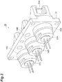
- the light source unit 10 includes a base 20, three light source assemblies 30A, 30B, and 30C, three support members 40A, 40B, and 40C, and three dichroic mirrors 50A, 50B, and 50C.
- the light source assemblies 30A, 30B, and 30C, the support members 40A, 40B, and 40C, and the dichroic mirrors 50A, 50B, and 50C are fixed to the base 20.
- Each of the light source assemblies 30A, 30B, and 30C includes a light source 31 that emits laser light L, a lens 32 disposed on an optical axis A of the laser light L, and a holding member 33 that integrally holds the light source 31 and the lens 32.
- the light source assembly 30A will be described with reference to FIG. 6 , but the light source assemblies 30B and 30C have a similar configuration with the light source assembly 30A.
- the light source 31 is, for example, a red laser diode, and emits laser light L for projection display.
- the light source 31 of the light source assembly 30B is, for example, a green laser diode
- the light source 31 of the light source assembly 30C is, for example, a blue laser diode.
- Each laser diode has, for example, a configuration in which a laser chip 8 is disposed in a package 7 including a stem 7a and a cap 7b, and emits laser light L from a light emission window provided in the cap 7b.
- the lens 32 is, for example, a convex lens and is a condensing lens that condenses the laser light L. The lens 32 is used to obtain a predetermined beam characteristic (spot size).
- the holding member 33 includes a light source holder 34 that holds the light source 31 and a lens holder 35 that holds the lens 32.
- the holding member 33 is made of a metal material such as stainless steel or the like.
- the light source holder 34 includes a fixing portion 36 to which the light source 31 is fixed, and an extending portion 37 extending cylindrically from the fixing portion 36.
- the light source holder 34 is formed in a substantially cylindrical shape as a whole, and surrounds the optical axis A of the light source 31.
- the light source 31 is fixed to the fixing portion 36 at an opening 36a provided in the fixing portion 36.
- the light source 31 emits laser light L toward the lens 32.
- a screw groove (first screw portion) 37a extending spirally around the optical axis A is provided on the inner peripheral surface of the extending portion 37.
- a protruding portion 38 protruding from the fixing portion 36 so as to be away from the optical axis A is provided on the outer peripheral surface of the fixing portion 36.
- the protruding portion 38 is disposed over the entire circumference of the outer circumferential surface of the fixing portion 36 and is formed in a substantially cylindrical shape.
- the projection 38 is provided with an inclined surface 38a inclined with respect to the optical axis A.
- the inclined surface 38a is, for example, a flat surface and extends in an annular shape when viewed from a direction parallel to the optical axis A (hereinafter, also referred to as an "optical axis direction").
- the inclined surface 38a is inclined so as to go toward the light emission side (the side where the lens 32 is located with respect to the light source 31 in the optical axis direction) as the distance from the optical axis A increases.
- An angle formed by the inclined surface 38a and the optical axis A in the cross section including the optical axis A is, for example, about 50 degrees.
- the outer edge of the inclined surface 38a is directly continuous with the outer surface of the protruding portion 38.
- the lens holder 35 is formed in a substantially cylindrical shape as a whole, and surrounds the optical axis A.
- the lens 32 is disposed in the lens holder 35 and fixed to the lens holder 35.
- a screw thread (second screw portion) 35a to be screwed with the screw groove 37a is provided on the outer peripheral surface of the lens holder 35.
- the screw thread 35a extends spirally around the optical axis A.
- a part of the lens holder 35 is inserted into the extending portion 37 of the light source holder 34, and the lens holder 35 is fixed to the light source holder 34 by screwing the screw thread 35a into the screw groove 37a.
- the light source holder 34 and the lens holder 35 can be moved relative to each other in the optical axis direction by adjusting the amount of screwing between the screw thread 35a and the screw groove 37a.
- the light source holder 34 and the lens holder 35 are moved relative to each other by adjusting the amount of screwing between the screw thread 35a and the screw groove 37a, so that the distance between the light source 31 and the lens 32 in the optical axis direction can be adjusted.
- the accuracy of the adjustment depends on the pitch of the thread 35a and the thread groove 37a.
- the pitch is 0.5 mm
- the distance adjustment amount by the relative rotation of 1 degree is about 1.4 ⁇ m obtained by dividing 0.5 mm by 360 degrees. Therefore, for example, by using a jig capable of adjusting an angle of about 1 degree, the positional relationship between the light source 31 and the lens 32 can be adjusted with a resolution of about several micrometers.
- the light source holder 34 and the lens holder 35 are also fixed to each other by a thermosetting resin provided between the screw thread 35a and the screw groove 37a. That is, when the light source assembly 30A is assembled, a thermosetting resin may be applied in advance between the screw thread 35a and the screw groove 37a, and the thermosetting resin may be heated and cured after the position between the light source 31 and the lens 32 is adjusted. As a result, the light source holder 34 and the lens holder 35 can be fixed more firmly. In addition to or instead of this, the light source holder 34 and the lens holder 35 can be fixed more firmly by making the tightening torque of the screw thread 35a and the screw groove 37a larger than that of a general screw structure.
- the holding member 33 includes the cylindrical main body surrounding the optical axis A and the protruding portion 38 protruding from the main body so as to be away from the optical axis A.
- the main body is formed by the fixing portion 36 and the extending portion 37 of the light source holder 34 and the lens holder 35.
- the light source assemblies 30A, 30B, and 30C are fixed to the base 20 at three openings 20a provided in the base 20 respectively.
- the dichroic mirrors 50A, 50B, and 50C are disposed so as to face the light source assemblies 30A, 30B, and 30C, respectively, via the openings 20a.
- the dichroic mirrors 50A, 50B, and 50C are bonded to the base 20 by resin.
- the resin material for the adhesion for example, a epoxy resin having a thermosetting characteristic can be used.
- the laser light L emitted from the light sources 31 of the light source assemblies 30A, 30B, and 30C enter the dichroic mirrors 50A, 50B, and 50C via the lenses 32 and the openings 20a, respectively.
- the laser light L from the light source assemblies 30A, 30B, and 30C are multiplexed (combined) by the dichroic mirror 50A, and reach the scanning mirror 6 via the light emission window 6a.
- the laser light L emitted from the light source 31 of the light source assembly 30A is reflected by the dichroic mirror 50A and reaches the scanning mirror 3.
- the laser light L emitted from the light source 31 of the light source assembly 30B is reflected by the dichroic mirror 50B, passes through the dichroic mirror 50A, and reaches the scanning mirror 3.
- the laser light L emitted from the light source 31 of the light source assembly 30C is reflected by the dichroic mirror 50C, passes through the dichroic mirrors 50A and 50B, and reaches the scanning mirror 3.
- the light source unit 10 further includes a light amount sensor 9 that detects the laser light L transmitted through the dichroic mirror 50A.
- the light amount sensor 9 is, for example, a photodiode, and is used to monitor the light amount of the laser light L emitted from the light source unit 10. In this example, the light amount sensor 9 is fixed to the base 20.
- the light source unit 10 will be further described with reference to FIGS. 7 to 11 .
- the fixing structure of the light source assembly 30A and the support member 40A to the base 20 will be described, but the fixing structure of the light source assemblies 30B and 30C and the support members 40B and 40C to the base 20 is configured in a similar manner.
- the light source assembly 30A is fixed to the base 20 via a support member 40A.
- the support member 40A is interposed between the attaching surface 20b of the base 20 and the light source assembly 30A.
- the attaching surface 20b is, for example, a flat surface.
- the support member 40A is made of, for example, the same material as the holding member 33.
- FIGS. 7 to 9 illustrate a state in which the optical axis A of the light source 31 coincides with the central axis X of the opening 20a of the base 20.
- the support member 40A has a sliding surface 41 and a receiving surface 42 in addition to a cylindrical outer peripheral surface.
- the sliding surface 41 is, for example, a flat surface and is in contact with the attaching surface 20b.
- the receiving surface 42 is a part of a surface of the support member 40A opposite to the base 20.
- the receiving surface 42 extends annularly and surrounds the optical axis A when viewed from the optical axis direction.
- the receiving surface 42 is a convex surface extending along a spherical surface, and has one center of curvature (spherical center) C.
- the center of curvature C is located on the optical axis A and is located on the light emission side with respect to the lens 32.
- a distance L1 from the center of curvature C to the lens 32 on the optical axis A is shorter than a distance L2 from the light emitting point Q of the light source 31 to the lens 32 on the optical axis A.
- the distance L1 is the distance from the center of curvature C to the surface of the lens 32 opposite to the light source 31 on the optical axis A.
- the distance L2 is a distance from the light emitting point Q to the surface of the lens 32 on the light source 31 side on the optical axis A.
- the distance L1 is 0.
- the distance L1 may be equal to or less than the thickness of the lens 32.
- the outer edge of the receiving surface 42 is directly continuous with the outer peripheral surface of the support member 40A.
- a part of the light source assembly 30A is disposed in the support member 40A and the opening 20a of the base 20. More particularly, the holding member 33 is disposed so as to penetrate the support member 40A and reach the opening 20a, and has a first portion 61 disposed in the space S defined by the support member 40A and a second portion 62 disposed in the opening 20a.
- the first portion 61 is constituted by a part of the extending portion 37 and the lens holder 35
- the second portion 62 is constituted by another part of the extending portion 37 and the lens holder 35.
- the holding member 33 is in contact with the receiving surface 42 at the inclined surface 38a of the protruding portion 38. More specifically, the holding member 33 is in contact with the receiving surface 42 at the entire periphery of the outer edge of the inclined surface 38a. That is, the holding member 33 is in line contact with the receiving surface 42.
- the light source assembly 30A is fixed to the support member 40A by coupling the holding member 33 to the receiving surface 42 at a contact portion with the receiving surface 42.
- the holding member 33 is coupled to the receiving surface 38a at the outer edge of the inclined surface 42 by laser welding.
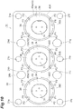
- the holding member 33 is coupled to the receiving surface 42 at, for example, four point-like coupling parts P1 shown in FIG. 10 .
- the irradiation direction of the laser light in the laser welding is, for example, a direction along the optical axis direction.
- the support member 40A is fixed to the base 20 by coupling the sliding surface 41 to the attaching surface 20b.
- the sliding surface 41 is coupled to the attaching surface 20b at the outer edge of the sliding surface 41 by laser welding.
- the support member 40A is coupled to the attaching surface 20b at, for example, four point-like coupling parts P2 shown in FIG. 10 .
- the irradiation direction of the laser light in the laser welding is, for example, a direction along the optical axis direction.
- the receiving surface 42 has an outer portion 42a located on a side away from the optical axis A of the light source 31 with respect to the coupling part P1 with the holding member 33.
- the outer portion 42a extends in an annular shape when viewed from the optical axis direction.
- the outer portion 42a is located outside the holding member 33 when viewed from the optical axis direction.
- the outer portion 42a is exposed from the holding member 33 (not covered by the holding member 33).
- the coupling part P1 of the holding member 33 to the receiving surface 42 is exposed.
- a cross section including the optical axis A cross section shown in FIG.
- an angle ⁇ formed by a tangent line B of the receiving surface 42 at a contact point P3 between the holding member 33 and the receiving surface 42 and an outer surface (in this example, the outer peripheral surface 38b of the protruding portion 38) continuous with the contact point P3 in the holding member 33 is an obtuse angle.
- the angle ⁇ is, for example, about 130 degrees.
- the light source assembly 30A is assembled (assembly step). That is, the light source holder 34 holding the light source 31 and the lens holder 35 holding the lens 32 are prepared and assembled to each other. Subsequently, the distance between the light source 31 and the lens 32 in the optical axis direction is adjusted by adjusting the amount of screwing between the screw thread 35a and the screw groove 37a to relatively move the light source holder 34 and the lens holder 35 (distance adjusting step).
- the support member 40A is disposed on the attaching surface 20b of the base 20, and the light source assembly 30A is disposed on the support member 40A such that the holding member 33 is in contact with the receiving surface 42 (disposing step).
- the inclination of the light source assembly 30A is adjusted by sliding the holding member 33 with respect to the receiving surface 42 (inclination adjusting step). More specifically, the inclination of the light source assembly 30A with respect to the base 20 is adjusted by sliding the outer edge of the inclined surface 38a of the protruding portion 38 with respect to the receiving surface 42.
- the inclination angle of the optical axis A of the light source 31 with respect to the central axis X of the opening 20a can be adjusted.
- FIG. 11 shows a state in which the optical axis A is inclined with respect to the central axis X.
- the position of the light source assembly 30A with respect to the base 20 in the direction perpendicular to the optical axis A is adjusted (position adjusting step).
- position adjusting step the position of the optical axis A with respect to the central axis X can be adjusted.
- the inclination adjusting step and the position adjusting step may be repeatedly performed such that the inclination angle and the position of the optical axis A with respect to the central axis X become a desired angle and position.
- Each of the inclination adjusting step and the position adjusting step may be performed once or a plurality of times.
- the inclination adjusting step and the position adjusting step may be performed in any order.
- the inclination angle and the position of the optical axis A with respect to the central axis X can be adjusted to a desired angle and position. Accordingly, for example, the laser light L is incident on the dichroic mirror 50A at a predetermined angle and position.
- the adjustment is necessary because the angle of the optical axis A may vary in the light source assembly 30A.
- the adjustment is necessary because the arrangement accuracy of the dichroic mirror 50A may vary due to the processing accuracy of the base 20.
- the support member 40A is fixed to the base 20 at the opening 20a, and the light source assembly 30A is fixed to the support member 40A at the opening 20a (fixing step).
- the support member 40A is fixed to the base 20 by joining the sliding surface 41 of the support member 40A to the attaching surface 20b of the base 20 by laser welding.
- the light source assembly 30A is fixed to the support member 40A by joining the holding member 33 to the receiving surface 42 at the contact portion with the receiving surface 42 by laser welding.
- the laser welding is performed by coupling the holding member 33 to the receiving surface 42 at the coupling-planned portion in a state where the receiving surface 42 has a portion (outer portion 42a) located on a side away from the optical axis A with respect to the coupling-planned portion with the holding member 33.
- the light source assemblies 30B and 30C and the support members 40B and 40C are fixed to the base 20 in a state where the inclination angles and positions of the optical axes A with respect to the central axes X are adjusted to desired angles and positions by the assembling step, the distance adjusting step, the disposing step, the inclination adjusting step, the position adjusting step, and the fixing step. Accordingly, the inclination angles and positions of the optical axes A of the light source assemblies 30A, 30B, and 30C and the support members 40A, 40B, and 40C can be adjusted with high accuracy, and as a result, the laser light L from the light source assemblies 30A, 30B, and 30C can be multiplexed with high accuracy.
- the inclination angles and positions of the optical axes A of the light source assemblies 30B, 30C and the support members 40B, 40C may be adjusted, and after the inclination angles and positions of the optical axes A of the light source assemblies 30A, 30B, 30C and the support members 40A, 40B, 40C are adjusted, the fixing step may be performed for the light source assemblies 30A, 30B, 30C and the support members 40A, 40B, 40C.
- the light source assembly 30A and the support 40A are configured such that the receiving surface 42 has a portion (outer portion 42a) located on the side away from the contact portion with the holding member 33 over the entire circumference even when the holding member 33 is slid with respect to the receiving surface 42 to a position (position shown in FIG. 11 ) where the optical axis A is maximally inclined with respect to the central axis X of the openings 20a in a state where the holding member 33 is not coupled to the receiving surface 42. That is, in the state shown in FIG. 11 , the outer portion 42a of the receiving surface 42 is exposed from the holding member 33 over the entire circumference (not covered by the holding member 33).
- the light source assembly 30A and the support member 40A are configured such that the portion of the extending portion 37 (first portion 61) on the side opposite to the base 20 comes into contact with the support member 40A before the portion of the extending portion 37 on the side of the base 20 comes into contact with the support member 40A when the holding member 33 is slid with respect to the receiving surface 42 such that the optical axis A are gradually inclined with respect to the central axis X.
- the fixing structure of the base 20 will be described with reference to FIG. 10 .
- the base 20 is fixed to, for example, a predetermined housing (not shown) by a fastening member (not shown) such as a bolt.
- the base 20 is provided with a plurality of through holes 21a to 21j.
- the through holes 21a to 21e are arranged on one side in the second direction with respect to the light source assemblies 30A, 30B, and 30C, and the through holes 21f to 21j are arranged on the other side in the second direction with respect to the light source assemblies 30A, 30B, and 30C.
- the first direction is the longitudinal direction of the base 20
- the second direction is the short direction of the base 20.
- the through holes 21a to 21j may have different sizes or the same size.
- the base 20 is fixed to the housing by fastening members at the through holes 21b, 21d, 21g, and 21i arranged around the light source assembly 30B. More specifically, bolts inserted through the through holes 21b, 21d, 21g, and 21i are fastened to fastening holes provided in the base 20, thereby fixing the base 20 to the housing.
- the base 20 is fixed in the through holes 21a, 21e, 21f, and 21j disposed at the four corners of the base 20, the base 20 is warped due to the influence of heat or the like, and the angle of the optical axis A may be deviated among the light source assemblies 30A, 30B, and 30C.
- the portions of the base 20 outside the fixing positions are only deformed so as to extend outward in the first direction. Therefore, it is possible to suppress the angle of the optical axis A from deviating among the light source assemblies 30A, 30B, and 30C.
- the plurality of fixing positions of the base 20 with respect to the housing may include only pairs of fixing positions that sandwich one of the light source assemblies 30A, 30B, and 30C in the second direction.
- the plurality of fixing positions may include only pairs of fixing positions that do not sandwich two or more of the light source assemblies 30A, 30B, and 30C in the second direction.
- the fixing position may be the position of the through holes 21a and 21j.
- the fixing position may be the position of the through holes 21b and 21j.
- the fixing positions may be the positions of the through holes 21c and 21h.
- the fixing positions may be the positions of the through holes 21d, 21e, 21f, and 21g.
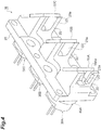
- the fixing structure of the dichroic mirrors 50A, 50B, and 50C will be described with reference to FIG. 4 , etc..
- the dichroic mirrors 50A, 50B, and 50C are fixed to the base 20 on the side opposite to the light source assemblies 30A, 30B, and 30C with respect to the base 20.
- the base 20 is provided with a plurality of fixing portions 22 for fixing the dichroic mirrors 50A, 50B, and 50C. As described above, the dichroic mirrors 50A, 50B, and 50C are bonded to the fixing portion 22 by resin.
- the fixed portion 22 is provided with a light passing portion 23 through which the laser light L reflected by the dichroic mirrors 50A, 50B, and 50C passes.
- the light passing portion 23 is open in the direction in which the laser light L is directed and is also open in the optical axis direction. That is, the light passing portion 23 has an opening portion 23a opened in the optical axis direction.
- the dichroic mirror 50A is formed in, for example, a rectangular shape and is bonded to the fixing portion 22 at four sides thereof, but is not in contact with or bonded to the fixing portion 22 at an intermediate portion of the first side 50Aa corresponding to the opening portion 23a.
- the dichroic mirror 50A is not in contact with or bonded to the fixing portion 22 also in the intermediate portion of the second side 50Ab opposite to the first side 50Aa.
- the fixing portion 22 has a shape that does not contact the intermediate portion of the second side 50Ab of the dichroic mirror 50A.
- the dichroic mirror 50A As a result, it is possible to prevent the position of the dichroic mirror 50A from deviating, and it is possible to improve the positional accuracy of the dichroic mirror 50A. That is, for example, in a case where the dichroic mirror 50A is not bonded to the fixing portion 22 at the intermediate portion of the first side 50Aa but is bonded to the fixing portion 22 at the entire second side 50Ab, there is a concern that the bonding balance of the dichroic mirror 50A is lost between the first side 50Aa side and the second side 50Ab side, and the position of the dichroic mirror 50A is shifted.
- the dichroic mirror 50A since the dichroic mirror 50A is not bonded to the fixing portion 22 at the intermediate portion of the second side 50Ab as well, the bonding balance of the dichroic mirror 50A can be improved, and as a result, the position of the dichroic mirror 50A can be prevented from being shifted.
- the dichroic mirrors 50B and 50C are also bonded to the fixing portion 22 in a similar manner with the dichroic mirror 50A, so that the positional accuracy is improved.
- the entire first side 50Aa may not be bonded to the fixing portion 22, and the entire second side 50Ab may not be bonded to the fixing portion 22.
- the support member 40A has the convex receiving surface 42 extending along the spherical surface so as to surround the optical axis A when viewed from the optical axis direction.
- the light source assembly 30A is fixed to the support member 40A by coupling the holding member 33 to the receiving surface 42 at a contact portion with the receiving surface 42.
- the inclination of the light source assembly 30A can be adjusted by sliding the holding member 33 with respect to the receiving surface 42.
- the position of the light source assembly 30A can also be adjusted by sliding the support member 40A together with the light source assembly 30A with respect to the base 20. Therefore, the position of the optical axis A of the laser light L can be adjusted with high accuracy.
- the receiving surface 42 has an outer portion 42a located on the side away from the optical axis A with respect to the coupling part P1 with the holding member 33. Accordingly, the holding member 33 can be easily coupled to the receiving surface 42, and the position of the optical axis A can be prevented from being displaced when the holding member 33 is coupled to the receiving surface 42. As described above, in the light source unit 10, the positional accuracy of the optical axis A of the laser light L is improved. Further, since the receiving surface 42 has the outer portion 42a, a welding margin between the holding member 33 and the receiving surface 42 can be sufficiently ensured, and the holding member 33 can be stably coupled to the receiving surface 42.
- the holding member 33 has the cylindrical main body surrounding the optical axis A and the projecting portion 38 projecting from the main body so as to be away from the optical axis A, and is in contact with and coupled to the receiving surface 42 at the projecting portion 38.
- the position of the optical axis A of the laser light L can be adjusted more accurately, and the holding member 33 can be more easily coupled to the receiving surface 42.
- the holding member 33 has the inclined surface 38a inclined with respect to the optical axis A, and is in contact with and coupled to the receiving surface 42 at the inclined surface 38a. Accordingly, the position of the optical axis A of the laser light L can be adjusted more accurately, and the holding member 33 can be more easily coupled to the receiving surface 42.
- the holding member 33 is in line contact with the receiving surface 42. Accordingly, the position of the optical axis A of the laser light L can be adjusted more accurately, and the holding member 33 can be more easily coupled to the receiving surface 42. Further, since the contact area between the holding member 33 and the support member 40A is reduced, the heat generated by the light source 31 can be easily transmitted not to the base 20 side but to the heat dissipation member (not shown) disposed on the side opposite to the base 20. As a result, the heat generated by the light source 31 can be efficiently dissipated.
- the holding member 33 is coupled to the receiving surface 42 by laser welding.
- the holding member 33 can be easily coupled to the receiving surface 42 by laser welding.
- the holding member 33 has the first part 61 disposed in the space S defined by the support member 40A. Thus, the light source unit 10 can be downsized.
- the holding member 33 has the second portion 62 disposed in the opening 20a of the base 20. Thus, the light source unit 10 can be further downsized.
- the light source assembly 30A and the support member 40A are configured such that when the holding member 33 is slid with respect to the receiving surface 42 such that the optical axis A is gradually inclined with respect to the central axis X of the openings 20a in a state where the holding member 33 is not coupled to the receiving surface 42, a portion of the extending portion 37 (first portion 61) on a side opposite to the base 20 contacts the support member 40A before a portion of the extending portion 37 on the base 20 side contacts the support member 40A. Accordingly, when the inclination of the light source assembly 30A is adjusted by sliding the holding member 33 with respect to the receiving surface 42, the portion of the extending portion 37 on the base 20 side can be prevented from contacting the support member 40A. As a result, it is possible to prevent the position of the lens 32 held on the base 20 side in the holding member 33 from shifting.
- the light source holder 34 is provided with the screw groove 37a
- the lens holder 35 is provided with the screw thread 35a to be screwed with the screw groove 37a so that the light source holder 37 and the lens holder 35 are relatively movable in the optical axis direction. Accordingly, when the light source unit 10 is manufactured, the distance between the light source 31 and the lens 32 in the optical axis direction can be adjusted by adjusting the amount of screwing between the screw groove 37a and the screw thread 35a.
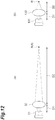
- FIG. 12(a) is a diagram illustrating a case where the condensing distance of the lens is long
- FIG. 12(b) is a diagram illustrating a case where the condensing distance of the lens is short.
- a condensing distance D2 between the lens 132 and the condensing point R is as short as, for example, about several millimeters, and a ratio of the condensing distance D2 to a distance D1 between the light source 131 and the lens 132 is small.
- the condensing distance D2 from the lens 32 to the condensing point R is relatively long, for example, about 150 mm, and the ratio of the condensing distance D2 to the distance D1 between the light source 31 and the lens 32 is large.
- the light source holder 35 and the lens holder 37 are fixed by screwing the screw thread 37a and the screw groove 35a, so that the positional relationship between the light source 31 and the lens 32 can be adjusted with a resolution of about several ⁇ m.
- the positional accuracy of the lens 32 with respect to the light source 31 can be improved compared to fixing by curing of a UV resin or fixing by welding using a YAG laser.
- the position of the lens 32 may vary due to expansion and contraction of the UV resin caused by a temperature change in the case of fixing with the UV resin, and in the case of welding using the YAG laser, the position deviation is likely to occur because the temperature of the welded portion becomes extremely high, and the required accuracy cannot be realized.
- laser welding is used to fix the light source assembly 30A to the support member 40A and to fix the support member 40A to the base 20.
- high accuracy of about several ⁇ m is not required at these fixing portions. This is because the positional relationship between the light source 31 and the lens 32 is already fixed at the time of assembling the light source assembly 30A, and even if the position of the light source assembly 30A is shifted at the time of fixing to the base 20, the positional shift does not appear to be magnified many times.
- positional deviation is less likely to occur even when a temperature change occurs after fixing, compared to fixing using resin.
- the distance L1 from the center of curvature C to the lens 32 on the optical axis A is shorter than the distance L2 from the light emitting point Q of the light source 31 to the lens 32 on the optical axis A.
- the holding member 33 is made of the same material as the support member 40A. As a result, since the thermal expansion coefficients of the holding member 33 and the support member 40A are the same, it is possible to suppress the positional deviation between the holding member 33 and the support member 40A due to the change in the ambient temperature.
- the dichroic mirror 50A is bonded to the base 20 by resin. This can simplify the manufacture of the light source unit 10. Since the heat generated by the light source 31 is hardly transmitted to the position where the dichroic mirror 50A is disposed, a resin can be used for coupling the dichroic mirror 50A to the base 20.
- the light source assembly 30A and the support member 40A are configured such that the receiving surface 42 has a portion (outer portion 42a) located on the side away from the optical axis A with respect to the contact portion with the holding member 33 even when the holding member 33 is slid with respect to the receiving surface 42 to a position where the optical axis A is maximally inclined with respect to the central axis X of the openings 20a in a state the holding member 33 is not coupled to the receiving surface 42. Accordingly, the position of the optical axis A of the laser light L can be adjusted more accurately, and the holding member 33 can be more easily coupled to the receiving surface 42.
- the receiving surface 42 has the outer portion 42a located outside the holding member 33 when viewed from the optical axis direction. Accordingly, the position of the optical axis A of the laser light L can be adjusted more accurately, and the holding member 33 can be more easily coupled to the receiving surface 42.
- the tangent line B of the receiving surface 42 at the contact point P3 between the holding member 33 and the receiving surface 42 forms an obtuse angle with an outer surface (in the above embodiment, the outer peripheral surface 38b of the protruding portion 38) continuous with the contact point P3 in the holding member 33. Accordingly, the position of the optical axis A of the laser light L can be adjusted more accurately, and the holding member 33 can be more easily coupled to the receiving surface 42.
- the fixing portion 36 to which the light source 31 is fixed has a portion 36b extending between the fixing portion of the light source 31 and the inclined surface 38a in the optical axis direction. Accordingly, the thickness of the fixing portion 36 in the direction perpendicular to the optical axis A can be increased, and the strength of the fixing portion 36 can be improved. Further, it is possible to prevent the temperature of the fixing portion 36 from increasing due to the heat from the light source 31.
- the protruding portion 38 includes a cylindrical first portion 38e and a second portion 38f protruding from the first portion 38e in the optical axis direction.
- the inclined surface 38a is provided in the second portion 38f. Accordingly, the thickness of the protruding portion 38 in the optical axis direction can be increased, and the strength of the protruding portion 38 can be improved. Further, it is possible to prevent the temperature of the protruding portion 38 from increasing due to heat from the light source 31. Thus, in combination with the fact that the holding member 33 is in line contact with the receiving surface 42, the heat generated by the light source 31 can be effectively prevented from being transmitted to the base 20 side.
- the distance between the light source 31 and the lens 32 in the optical axis direction is adjusted by adjusting the amount of screwing between the light source holder 34 and the lens holder 35 (distance adjusting step). Accordingly, the positional relationship between the light source 31 and the lens 32 can be adjusted with high accuracy.
- the support member 40A is fixed to the base 20, and the light source assembly 30A is fixed to the support member 40A by coupling the holding member 33 to the receiving surface 42 at the contact portion with the receiving surface 42 (fixing step).
- each element can be fixed after the position of the optical axis A of the laser light L is accurately adjusted. Therefore, according to the above-described manufacturing method, it is possible to obtain the light source unit 10 in which the positional accuracy of the optical axis A of the laser light L is improved.
- the above-described manufacturing method includes, between the disposing step and the fixing step, the position adjusting step of adjusting the position of the light source assembly 30A by sliding the support member 40A together with the light source assembly 30A with respect to the base 20.
- each element can be fixed after the position of the optical axis A of the laser light L is more accurately adjusted.
- the light source assembly 30A is fixed to the support member 40A by coupling the holding member 33 to the receiving surface 42 at the coupling-planned portion in a state in which the receiving surface 42 has the outer portion 42a located on the side away from the optical axis A with respect to the coupling-planned portion with the holding member 33.
- the positional accuracy of the optical axis A of the laser light L can be further enhanced.
- the light source assembly 30A is fixed to the support member 40A by coupling the holding member 33 to the receiving surface 42 at the contact portion with the receiving surface 42 by laser welding. According to the above-described manufacturing method, even when the holding member 33 is coupled to the receiving surface 42 by laser welding, the positional accuracy of the optical axis A of the laser light L can be improved.
- the light source assembly 30A and the support member 40A may be configured as in the first to third modifications shown in FIGS. 13(a) to 13(c) or the fourth to sixth modifications shown in FIGS. 14(a) to 14(c) .
- FIGS. 13(a) to 13(c) and FIGS. 14(a) to 14(c) the periphery of the protruding portion 38 of the holding member 33 and the receiving surface 42 of the support member 40A is schematically and partially shown.
- the inclined surface 38a of the protruding portion 38 is inclined so as to go toward the side opposite to the light emission side (the side where the light source 31 is located with respect to the lens 32 in the optical axis direction) as the distance from the optical axis A increases.
- the holding member 33 is in contact with the receiving surface 42 at the inner edge of the inclined surface 38a.
- the receiving surface 42 has an outer portion 42a.
- the coupling part P1 of the holding member 33 to the receiving surface 42 overlaps the holding member 33 and is not exposed when viewed from the optical axis direction, but is exposed when viewed from the direction perpendicular to the optical axis A.
- the coupling part P1 is exposed when viewed from a direction Y slightly inclined to the side opposite to the light emission side with respect to the direction perpendicular to the optical axis A. That is, the coupling part P1 is exposed when viewed from a position away from a straight line orthogonal to the optical axis A and passing through the coupling part P1 toward the light emission side.
- an angle ⁇ formed by a tangent line B of the receiving surface 42 at a contact point P3 between the holding member 33 and the receiving surface 42 and an outer surface (in this example, the inclined surface 38a) continuous with the contact point P3 in the holding member 33 is an obtuse angle.
- the protruding portion 38 does not have the inclined surface 38a but has a cylindrical portion 38c.
- the holding member 33 is in line contact with the receiving surface 42 at the inner edge of the distal end of the cylindrical portion 38c.
- the receiving surface 42 has an outer portion 42a.
- the coupling part P1 of the holding member 33 to the receiving surface 42 overlaps the holding member 33 and is not exposed when viewed from the optical axis direction, but is exposed when viewed from the direction perpendicular to the optical axis A.
- the coupling part P1 is not exposed when viewed from a direction Y slightly inclined to the side opposite to the light emission side with respect to the direction perpendicular to the optical axis A.
- an angle ⁇ formed by a tangent line B of the receiving surface 42 at a contact point P3 between the holding member 33 and the receiving surface 42 and an outer surface (in this example, a distal end surface of the cylindrical portion 38c) continuous with the contact point P3 in the holding member 38 is an acute angle.
- the protruding portion 38 has a concave contact surface 38d extending along a spherical surface instead of the inclined surface 38a.
- the center of curvature of the contact surface 38d does not coincide with the center of curvature of the receiving surface 42.
- the holding member 33 is in line contact with the receiving surface 42 at the outer edge of the contact surface 38d.
- the receiving surface 42 has an outer portion 42a.
- the coupling part P1 of the holding member 33 to the receiving surface 42 is exposed both when viewed from the optical axis direction and when viewed from the direction perpendicular to the optical axis A.
- an angle ⁇ formed by a tangent line B of the receiving surface 42 at a contact point P3 between the holding member 33 and the receiving surface 42 and an outer surface (in this example, an outer peripheral surface of the protruding portion 38) continuous with the contact point P3 in the holding member 33 is an obtuse angle.
- the fourth modification shown in FIG. 14(a) is different from the third modification in the outer shape of the protruding portion 38.
- the receiving surface 42 has an outer portion 42a.
- the coupling part P1 of the holding member 33 to the receiving surface 42 overlaps the holding member 33 and is not exposed when viewed from the optical axis direction, but is exposed when viewed from the direction perpendicular to the optical axis A.
- the coupling part P1 is exposed when viewed from a direction Y slightly inclined to the side opposite to the light emission side with respect to the direction perpendicular to the optical axis A.
- an angle ⁇ formed by a tangent line B of the receiving surface 42 at a contact point P3 between the holding member 33 and the receiving surface 42 and an outer surface (in this example, an outer surface of the protruding portion 38) continuous with the contact point P3 in the holding member 33 is an acute angle.
- the fifth modification shown in FIG. 14(b) is different from the third modification in the outer shape of the protruding portion 38.
- the receiving surface 42 has an outer portion 42a.
- the coupling part P1 of the holding member 33 to the receiving surface 42 overlaps the holding member 33 and is not exposed when viewed from the optical axis direction, but is exposed when viewed from the direction perpendicular to the optical axis A.
- the coupling part P1 is not exposed when viewed from a direction Y slightly inclined to the side opposite to the light emission side with respect to the direction perpendicular to the optical axis A.
- an angle ⁇ formed by a tangent line B of the receiving surface 42 at a contact point P3 between the holding member 33 and the receiving surface 42 and an outer surface (in this example, a distal end surface of the protruding portion 38) continuous with the contact point P3 in the holding member 33 is an acute angle.
- the protruding portion 38 has a contact surface 38d along a concave spherical surface instead of the inclined surface 38a.
- the center of curvature of the contact surface 38d coincides with the center of curvature of the receiving surface 42.
- the holding member 33 is in surface contact with the receiving surface 42 at the contact surface 38d.
- the holding member 33 is coupled to the receiving surface 42 at the outer edge of the contact surface 38d.
- the receiving surface 42 has an outer portion 42a.
- the coupling part P1 of the holding member 33 to the receiving surface 42 is exposed both when viewed from the optical axis direction and when viewed from the direction perpendicular to the optical axis A. According to the first to sixth modifications, the positional accuracy of the optical axis A of the laser light L can be improved as in the above embodiment.
- the protruding portion 38 is disposed over the entire circumference of the outer circumferential surface of the fixing portion 36.
- the protruding portion 38 may be configured by a plurality of protruding portions arranged along the circumferential direction on the outer circumferential surface of the fixing portion 36. That is, the protruding portion 38 may be partially disposed in the circumferential direction.
- the holding member 33 may not contact and be coupled to the receiving surface 42 at the protrusion 38.
- the end portion of the lens holder 35 on the base 20 side may be brought into contact with and coupled to the receiving surface 42.
- the holding member 33 may not be provided with the protruding portion 38.
- the center of curvature C of the receiving surface 42 may be located on the lens 32.
- the holding member 33 may be coupled to the receiving surface 42 by a welding means other than laser welding or an adhesive made of a resin material.
- the support member 40A may be coupled to the base 20 by a welding means other than laser welding or an adhesive made of a resin material.
- the coupling means of the holding member 33 to the receiving surface 42 may be different from the coupling means of the support member 40A to the base 20.
- the optical axes A of the light source assemblies 30A, 30B, and 30C are parallel to each other, but at least one optical axis A of the light source assemblies 30A, 30B, and 30C may intersect (for example, be orthogonal to) the optical axes A of the other light source assemblies 30A, 30B, and 30C.
- the base 20 (attaching surface 20b) may be formed in an L shape or a U shape when viewed from a direction perpendicular to the optical axis A.
- the holding member 33 may not be coupled to the receiving surface 42.
- the light source assembly 30A may be fixed to the base 20 by directly coupling the holding member 33 to the base 20 on the outer side of the support member 40A.
- the holding member 33 may be coupled to the receiving surface 42 at a portion of the receiving surface 42 on the inner side (the side closer to the optical axis A) of the contact point P3 between the holding member 33 and the receiving surface 42.
- an adhesive made of a resin material may be applied to the inner portion (and the contact point P3), and the resin material may be heated and cured after assembly.
- the receiving surface 42 may extend so as to surround the optical axis A, and may not necessarily surround the optical axis A over the entire circumference.
- the receiving surface 42 may be discontinuous in a part of the circumferential direction by forming a notch or the like in the receiving surface 42. That is, the receiving surface 42 may partially surround the optical axis A and may extend around the optical axis A.
- the support member 40A may not be formed in a cylindrical shape and may be formed in a C-shape when viewed from the optical axis direction, for example.
- the receiving surface 42 may have a spherical shape.
- Such a spherical surface includes a spherical surface having different radius of curvature at a plurality of points due to manufacturing errors or the like.
- the spherical surface may be a surface having a radius of curvature within a range of ⁇ 0.1 mm of a set value.
- 1 projection display device
- 4 light diffuser
- 10 light source unit
- 20 base
- 20a opening
- 30A, 30B, 30C light source assembly
- 31 light source
- 32 lens
- 33 holding member
- 34 light source holder
- 35 lens holder
- 35a thread (second screwing part)
- 37a thread groove (first screwing part)
- 38 protruding portion
- 38a inclined surface
- 40A, 40B, 40C support member
- 42 receiving surface
- 42a outer portion
- 50A, 50B, 50C dichroic mirror
- 61 first portion
- 62 second portion
- A optical axis
- B tangent line
- C center of curvature
- L laser light
- P1 coupling part
- P3 contact point
- X center axis
Landscapes
- Physics & Mathematics (AREA)
- General Physics & Mathematics (AREA)
- Optics & Photonics (AREA)
- Multimedia (AREA)
- Signal Processing (AREA)
- Engineering & Computer Science (AREA)
- Electromagnetism (AREA)
- Condensed Matter Physics & Semiconductors (AREA)
- Semiconductor Lasers (AREA)
- Projection Apparatus (AREA)
- Transforming Electric Information Into Light Information (AREA)
- Mechanical Optical Scanning Systems (AREA)
- Fastening Of Light Sources Or Lamp Holders (AREA)
Abstract
Description
- An aspect of the present disclosure relates to a light source unit, a projection display device, and a method for manufacturing a light source unit.
- There has been light source units that include a base provided with an opening, a cylindrical support member fixed to the base at the opening, and a light source assembly fixed to the support member at the opening (for example, see
Patent Literature 1, 2). The light source assembly includes a light source that emits laser light and a lens disposed on an optical axis of the laser light. The laser light emitted from the light source is condensed by the lens and passes through the opening of the base. -
- Patent Literature 1:
Japanese Unexamined Patent Publication No. 2010-263070 - Patent Literature 2:
Japanese Unexamined Patent Publication No. 2011-151308 - In the light source units as described above, extremely high accuracy is required for the position of the optical axis of the laser light. Therefore, it is an object of an aspect of the present disclosure to provide a light source unit and a projection display device in which the positional accuracy of the optical axis of the laser light is improved, and a method for manufacturing such a light source unit.
- A light source unit according to an aspect of the present disclosure includes: a base provided with an opening; a support member fixed to the base at the opening; a light source assembly fixed to the support member at the opening; in which the light source assembly includes a light source that emits laser light, a lens disposed on an optical axis of the laser light, and a holding member that holds the light source and the lens, the support member has a convex receiving surface extending along a spherical surface so as to surround the optical axis when viewed from a direction parallel to the optical axis, the light source assembly is fixed to the support member by coupling the holding member to the receiving surface at a contact portion with the receiving surface, and the receiving surface has a portion located on a side away from the optical axis with respect to a coupling part with the holding member.
- In this light source unit, the support member has a convex receiving surface extending along a spherical surface so as to surround the optical axis of the laser light when viewed from a direction parallel to the optical axis. The light source assembly is fixed to the support member by coupling the holding member to the receiving surface at a contact portion with the receiving surface. When the light source unit is manufactured, for example, the inclination of the light source assembly can be adjusted by sliding the holding member with respect to the receiving surface. Further, the position of the light source assembly can be adjusted by sliding the support member together with the light source assembly with respect to the base. Therefore, the position of the optical axis of the laser light can be adjusted with high accuracy. Further, in this light source unit, the receiving surface has a portion located on the side away from the optical axis with respect to the coupling part with the holding member. Accordingly, the holding member can be easily coupled to the receiving surface, and the position of the optical axis of the laser light can be prevented from being shifted when the holding member is coupled to the receiving surface. As described above, in this light source unit, the positional accuracy of the optical axis of the laser light is improved.
- The holding member may include a cylindrical main body surrounding the optical axis and a protruding portion protruding from the main body so as to be away from the optical axis, and may be in contact with and coupled to the receiving surface at the protruding portion. In this case, the position of the optical axis of the laser light can be adjusted more accurately, and the holding member can be more easily coupled to the receiving surface.
- The holding member may have an inclined surface inclined with respect to the optical axis, and may be in contact with and coupled to the receiving surface at the inclined surface. In this case, the position of the optical axis of the laser light can be adjusted more accurately, and the holding member can be more easily coupled to the receiving surface.
- The holding member may be in line contact with the receiving surface. In this case, the position of the optical axis of the laser light can be adjusted more accurately, and the holding member can be more easily coupled to the receiving surface.
- The holding member may have a concave contact surface extending along the spherical surface, and may be in contact with and coupled to the receiving surface at the contact surface. Also in this case, the position of the optical axis of the laser light can be adjusted with high accuracy, and the holding member can be easily coupled to the receiving surface.
- The holding member may be coupled to the receiving surface by laser welding. In this light source unit, the holding member can be easily coupled to the receiving surface by laser welding.
- The holding member may have a first portion disposed in a space defined by the support member. In this case, the light source unit can be downsized.
- The holding member may have a second portion disposed in the opening of the base. In this case, the light source unit can be further downsized.
- The light source assembly and the support member may be configured such that a portion of the first portion on a side opposite to the base contacts the support member before a portion of the first portion on a side of the base contacts the support member when the holding member is slid with respect to the receiving surface such that the optical axis is gradually inclined with respect to a central axis of the opening in a state where the holding member is not coupled to the receiving surface. In this case, when the inclination of the light source assembly is adjusted by sliding the holding member with respect to the receiving surface, the portion of the first portion on the side of the base can be prevented from coming into contact with the support member. As a result, it is possible to prevent the position of the lens held on the base side in the holding member from shifting.
- The holding member may include a light source holder that holds the light source and a lens holder that holds the lens, the light source holder may be provided with a first screw portion, and the lens holder may be provided with a second screw portion that is screwed with the first screw portion so that the light source holder and the lens holder are relatively movable in a direction parallel to the optical axis. In this case, when the light source unit is manufactured, the distance between the light source and the lens in the direction parallel to the optical axis can be adjusted by adjusting the amount of screwing between the first screwing portion and the second screwing portion.
- A distance from a center of curvature of the receiving surface to the lens on the optical axis may be shorter than a distance from a light emitting point of the light source to the lens on the optical axis. In this case, the amount of movement of the lens when the inclination of the light source assembly is adjusted by sliding the holding member with respect to the receiving surface can be reduced.
- The holding member may be made of the same material as the support member. In this case, since the holding member and the support member have the same thermal expansion coefficient, positional deviation between the holding member and the support member due to a change in ambient temperature can be suppressed.
- The light source unit according to an aspect of the present disclosure may further include a dichroic mirror on which the laser light emitted from the lens is incident, and the dichroic mirror may be bonded to the base by resin. In this case, the manufacture of the light source unit can be simplified.
- The light source assembly and the support member may be configured such that the receiving surface has a portion located on a side away from the optical axis with respect to a contact portion with the holding member over an entire circumference when the holding member is slid with respect to the receiving surface to a position where the optical axis is maximally inclined with respect to a central axis of the opening in a state where the holding member is not coupled to the receiving surface. In this case, the position of the optical axis of the laser light can be adjusted more accurately, and the holding member can be more easily coupled to the receiving surface.
- The receiving surface may have a portion located outside the holding member when viewed from a direction parallel to the optical axis. In this case, the position of the optical axis of the laser light can be adjusted more accurately, and the holding member can be more easily coupled to the receiving surface.
- In a cross section including the optical axis, a tangent line of the receiving surface at a contact point between the holding member and the receiving surface may form an obtuse angle with an outer surface of the holding member continuous with the contact point. In this case, the position of the optical axis of the laser light can be adjusted more accurately, and the holding member can be more easily coupled to the receiving surface.
- A projection display device according to an aspect of the present disclosure includes the light source unit described above and a light diffuser that transmits and diffuses laser light emitted from the light source unit. In this projection display device, the positional accuracy of the optical axis of the laser light is enhanced for the reasons described above.
- A method for manufacturing a light source unit according to an aspect of the present disclosure including: a distance adjusting step of adjusting, in a holding member of a light source assembly including a light source that emits a laser light, a lens disposed on an optical axis of the laser light and the holding member that holds the light source and the lens, a distance between the light source and the lens in a direction parallel to the optical axis of the laser light by adjusting a screwing amount between a light source holder holding the light source and a lens holder holding the lens; a disposing step of disposing a cylindrical support member on a base provided with an opening, the cylindrical support member having a convex receiving surface extending along a spherical surface so as to surround the optical axis when viewed from a direction parallel to the optical axis, and disposing the light source assembly on the support member such that the holding member is in contact with the receiving surface, after the distance adjusting step; an inclination adjusting step of adjusting an inclination of the light source assembly by sliding the holding member with respect to the receiving surface, after the disposing step; and a fixing step of fixing the light source assembly to the support member at the opening by fixing the support member to the base at the opening and coupling the holding member to the receiving surface at a contact portion with the receiving surface, after the inclination adjusting step.
- In this method for manufacturing a light source unit, the distance between the light source and the lens in the direction parallel to the optical axis of the laser light is adjusted by adjusting the amount of screwing between the light source holder and the lens holder (distance adjusting step). Accordingly, the positional relationship between the light source and the lens can be adjusted with high accuracy. After the inclination of the light source assembly is adjusted by sliding the holding member with respect to the receiving surface (inclination adjusting step), the support member is fixed to the base, and the light source assembly is fixed to the support member by coupling the holding member to the receiving surface at a contact portion with the receiving surface (fixing step). Thus, each element can be fixed after the position of the optical axis of the laser light is accurately adjusted. Therefore, according to the method for manufacturing the light source unit, it is possible to obtain the light source unit in which the positional accuracy of the optical axis of the laser light is improved.
- The light source unit according to an aspect of the present disclosure may further include a position adjusting step of adjusting the position of the light source assembly by sliding the support member together with the light source assembly with respect to the base, between the disposing step and the fixing step. In this case, each element can be fixed after the position of the optical axis of the laser light is adjusted more accurately.
- In the fixing step, the light source assembly may be fixed to the support member by coupling the holding member to the receiving surface at a coupling-planned portion in a state in which the receiving surface has a portion located on a side away from the optical axis with respect to the coupling-planned portion with the holding member. In this case, the positional accuracy of the optical axis of the laser light can be further improved.
- In the fixing step, the light source assembly may be fixed to the support member by coupling the holding member to the receiving surface at a contact portion with the receiving surface by laser welding. According to this method for manufacturing a light source unit, even when the holding member is coupled to the receiving surface by laser welding, the positional accuracy of the optical axis of the laser light can be improved.
- According to an aspect of the present disclosure, it is possible to provide a light source unit and a projection display device in which the positional accuracy of the optical axis of laser light is improved, and a method for manufacturing such a light source unit.
-
-
FIG. 1 is a schematic configuration diagram of a projection display device according to an embodiment. -
FIG. 2 is a perspective view of a light source device. -
FIG. 3 is a perspective view of a light source unit as viewed from one side. -
FIG. 4 is a perspective view of the light source unit as viewed from the other side. -
FIG. 5 is a sectional view of a light source unit. -
FIG. 6 is a sectional view of a light source assembly. -
FIG. 7 is a sectional view showing a fixing structure of the light source assembly. -
FIG. 8 is a sectional view of a light source unit before assembly. -
FIG. 9 is a sectional view of the light source unit after assembly. -
FIG. 10 is a view illustrating a light source unit as viewed from a direction parallel to an optical axis. -
FIG. 11 is a sectional view illustrating a state in which the light source assembly is inclined. -
FIG. 12(a) is a diagram illustrating a case in which the condensing distance of the lens is long, andFIG. 12(b) is a diagram illustrating a case in which the condensing distance of the lens is short. -
FIGS. 13(a) to 13(c) are schematic views illustrating modifications. -
FIGS. 14(a) to 14(c) are schematic views illustrating modifications. - Hereinafter, an embodiment of the present disclosure will be described in detail with reference to the drawings. In the following description, the same reference numerals are used for the same or corresponding element, and redundant description is omitted.
- As shown in
FIG. 1 , theprojection display device 1 includes alight source device 2 and alight diffuser 4. Theprojection display device 1 is, for example, a laser-scanning projection display (head-up display) mounted on an automobile, and projects and displays an image on the windshield of the automobile. Thelight source device 2 emits laser light L for projection display. - The
light source device 2 includes ascanning mirror 3. Thescanning mirror 3 is, for example, an electromagnetically driven optical mirror manufactured by MEMS (Micro Electro Mechanical Systems) technology. By swinging themirror 3a, thescanning mirror 3 reflects the laser light L emitted from thelight source device 2 and scans the laser light L in a predetermined region of thelight diffuser 4. - The
light diffuser 4 is, for example, a microlens array having a plurality of microlenses arranged in matrix, and transmits and diffuses the laser light L for projection display scanned by thescanning mirror 3. The incident surface of thelight diffuser 4 is a flat surface, and the emission surface of thelight diffuser 4 is constituted by a plurality of convex surfaces corresponding to the plurality of microlenses. The laser light L diffused by thelight diffuser 4 is guided to the windshield of the automobile via, for example, a plurality of mirrors, and reaches the eyes of the driver as an image via reflection at the windshield. - As shown in
FIGS. 1 to 5 , thelight source device 2 includes, in addition to thescanning mirror 3, alight source unit 10, and a box-shapedhousing 6 that accommodates thescanning mirror 3 and thelight source unit 10. Thehousing 6 is provided with alight emission window 6a through which light is emitted from thelight source device 2 to the outside. - The
light source unit 10 includes abase 20, threelight source assemblies support members dichroic mirrors light source assemblies support members dichroic mirrors base 20. - Each of the
light source assemblies light source 31 that emits laser light L, alens 32 disposed on an optical axis A of the laser light L, and a holdingmember 33 that integrally holds thelight source 31 and thelens 32. Hereinafter, thelight source assembly 30A will be described with reference toFIG. 6 , but thelight source assemblies light source assembly 30A. - The
light source 31 is, for example, a red laser diode, and emits laser light L for projection display. Thelight source 31 of thelight source assembly 30B is, for example, a green laser diode, and thelight source 31 of thelight source assembly 30C is, for example, a blue laser diode. Each laser diode has, for example, a configuration in which alaser chip 8 is disposed in a package 7 including astem 7a and acap 7b, and emits laser light L from a light emission window provided in thecap 7b. Thelens 32 is, for example, a convex lens and is a condensing lens that condenses the laser light L. Thelens 32 is used to obtain a predetermined beam characteristic (spot size). - The holding
member 33 includes alight source holder 34 that holds thelight source 31 and alens holder 35 that holds thelens 32. The holdingmember 33 is made of a metal material such as stainless steel or the like. Thelight source holder 34 includes a fixingportion 36 to which thelight source 31 is fixed, and an extendingportion 37 extending cylindrically from the fixingportion 36. Thelight source holder 34 is formed in a substantially cylindrical shape as a whole, and surrounds the optical axis A of thelight source 31. Thelight source 31 is fixed to the fixingportion 36 at anopening 36a provided in the fixingportion 36. Thelight source 31 emits laser light L toward thelens 32. A screw groove (first screw portion) 37a extending spirally around the optical axis A is provided on the inner peripheral surface of the extendingportion 37. - A protruding
portion 38 protruding from the fixingportion 36 so as to be away from the optical axis A is provided on the outer peripheral surface of the fixingportion 36. In this example, the protrudingportion 38 is disposed over the entire circumference of the outer circumferential surface of the fixingportion 36 and is formed in a substantially cylindrical shape. Theprojection 38 is provided with aninclined surface 38a inclined with respect to the optical axis A. Theinclined surface 38a is, for example, a flat surface and extends in an annular shape when viewed from a direction parallel to the optical axis A (hereinafter, also referred to as an "optical axis direction"). Theinclined surface 38a is inclined so as to go toward the light emission side (the side where thelens 32 is located with respect to thelight source 31 in the optical axis direction) as the distance from the optical axis A increases. An angle formed by theinclined surface 38a and the optical axis A in the cross section including the optical axis A is, for example, about 50 degrees. In this example, the outer edge of theinclined surface 38a is directly continuous with the outer surface of the protrudingportion 38. - The
lens holder 35 is formed in a substantially cylindrical shape as a whole, and surrounds the optical axis A. Thelens 32 is disposed in thelens holder 35 and fixed to thelens holder 35. A screw thread (second screw portion) 35a to be screwed with thescrew groove 37a is provided on the outer peripheral surface of thelens holder 35. Thescrew thread 35a extends spirally around the optical axis A. A part of thelens holder 35 is inserted into the extendingportion 37 of thelight source holder 34, and thelens holder 35 is fixed to thelight source holder 34 by screwing thescrew thread 35a into thescrew groove 37a. Thelight source holder 34 and thelens holder 35 can be moved relative to each other in the optical axis direction by adjusting the amount of screwing between thescrew thread 35a and thescrew groove 37a. - When the
light source assembly 30A is assembled, thelight source holder 34 and thelens holder 35 are moved relative to each other by adjusting the amount of screwing between thescrew thread 35a and thescrew groove 37a, so that the distance between thelight source 31 and thelens 32 in the optical axis direction can be adjusted. The accuracy of the adjustment depends on the pitch of thethread 35a and thethread groove 37a. For example, when the pitch is 0.5 mm, the distance adjustment amount by the relative rotation of 1 degree is about 1.4 µm obtained by dividing 0.5 mm by 360 degrees. Therefore, for example, by using a jig capable of adjusting an angle of about 1 degree, the positional relationship between thelight source 31 and thelens 32 can be adjusted with a resolution of about several micrometers. - In this example, the
light source holder 34 and thelens holder 35 are also fixed to each other by a thermosetting resin provided between thescrew thread 35a and thescrew groove 37a. That is, when thelight source assembly 30A is assembled, a thermosetting resin may be applied in advance between thescrew thread 35a and thescrew groove 37a, and the thermosetting resin may be heated and cured after the position between thelight source 31 and thelens 32 is adjusted. As a result, thelight source holder 34 and thelens holder 35 can be fixed more firmly. In addition to or instead of this, thelight source holder 34 and thelens holder 35 can be fixed more firmly by making the tightening torque of thescrew thread 35a and thescrew groove 37a larger than that of a general screw structure. - As described above, the holding
member 33 includes the cylindrical main body surrounding the optical axis A and the protrudingportion 38 protruding from the main body so as to be away from the optical axis A. In this example, the main body is formed by the fixingportion 36 and the extendingportion 37 of thelight source holder 34 and thelens holder 35. - As shown in
FIGS. 5 and7 , thelight source assemblies openings 20a provided in thebase 20 respectively. The dichroic mirrors 50A, 50B, and 50C are disposed so as to face thelight source assemblies openings 20a. The dichroic mirrors 50A, 50B, and 50C are bonded to thebase 20 by resin. As the resin material for the adhesion, for example, a epoxy resin having a thermosetting characteristic can be used. - The laser light L emitted from the
light sources 31 of thelight source assemblies dichroic mirrors lenses 32 and theopenings 20a, respectively. The laser light L from thelight source assemblies dichroic mirror 50A, and reach thescanning mirror 6 via thelight emission window 6a. - More specifically, the laser light L emitted from the
light source 31 of thelight source assembly 30A is reflected by thedichroic mirror 50A and reaches thescanning mirror 3. The laser light L emitted from thelight source 31 of thelight source assembly 30B is reflected by thedichroic mirror 50B, passes through thedichroic mirror 50A, and reaches thescanning mirror 3. The laser light L emitted from thelight source 31 of thelight source assembly 30C is reflected by thedichroic mirror 50C, passes through thedichroic mirrors scanning mirror 3. - A part of the combined laser light L passes through the
dichroic mirror 50A. Thelight source unit 10 further includes alight amount sensor 9 that detects the laser light L transmitted through thedichroic mirror 50A. Thelight amount sensor 9 is, for example, a photodiode, and is used to monitor the light amount of the laser light L emitted from thelight source unit 10. In this example, thelight amount sensor 9 is fixed to thebase 20. - The
light source unit 10 will be further described with reference toFIGS. 7 to 11 . Hereinafter, the fixing structure of thelight source assembly 30A and thesupport member 40A to the base 20 will be described, but the fixing structure of thelight source assemblies support members base 20 is configured in a similar manner. - The
light source assembly 30A is fixed to thebase 20 via asupport member 40A. Thesupport member 40A is interposed between the attachingsurface 20b of thebase 20 and thelight source assembly 30A. The attachingsurface 20b is, for example, a flat surface. Thesupport member 40A is made of, for example, the same material as the holdingmember 33.FIGS. 7 to 9 illustrate a state in which the optical axis A of thelight source 31 coincides with the central axis X of theopening 20a of thebase 20. - The
support member 40A has a slidingsurface 41 and a receivingsurface 42 in addition to a cylindrical outer peripheral surface. The slidingsurface 41 is, for example, a flat surface and is in contact with the attachingsurface 20b. The receivingsurface 42 is a part of a surface of thesupport member 40A opposite to thebase 20. The receivingsurface 42 extends annularly and surrounds the optical axis A when viewed from the optical axis direction. The receivingsurface 42 is a convex surface extending along a spherical surface, and has one center of curvature (spherical center) C. The center of curvature C is located on the optical axis A and is located on the light emission side with respect to thelens 32. A distance L1 from the center of curvature C to thelens 32 on the optical axis A is shorter than a distance L2 from the light emitting point Q of thelight source 31 to thelens 32 on the optical axis A. In this example, the distance L1 is the distance from the center of curvature C to the surface of thelens 32 opposite to thelight source 31 on the optical axis A. The distance L2 is a distance from the light emitting point Q to the surface of thelens 32 on thelight source 31 side on the optical axis A. When the center of curvature C is located on thelens 32, the distance L1 is 0. The distance L1 may be equal to or less than the thickness of thelens 32. In this example, the outer edge of the receivingsurface 42 is directly continuous with the outer peripheral surface of thesupport member 40A. - A part of the
light source assembly 30A is disposed in thesupport member 40A and theopening 20a of thebase 20. More particularly, the holdingmember 33 is disposed so as to penetrate thesupport member 40A and reach theopening 20a, and has afirst portion 61 disposed in the space S defined by thesupport member 40A and asecond portion 62 disposed in theopening 20a. In this example, thefirst portion 61 is constituted by a part of the extendingportion 37 and thelens holder 35, and thesecond portion 62 is constituted by another part of the extendingportion 37 and thelens holder 35. - The holding
member 33 is in contact with the receivingsurface 42 at theinclined surface 38a of the protrudingportion 38. More specifically, the holdingmember 33 is in contact with the receivingsurface 42 at the entire periphery of the outer edge of theinclined surface 38a. That is, the holdingmember 33 is in line contact with the receivingsurface 42. Thelight source assembly 30A is fixed to thesupport member 40A by coupling the holdingmember 33 to the receivingsurface 42 at a contact portion with the receivingsurface 42. In this example, the holdingmember 33 is coupled to the receivingsurface 38a at the outer edge of theinclined surface 42 by laser welding. The holdingmember 33 is coupled to the receivingsurface 42 at, for example, four point-like coupling parts P1 shown inFIG. 10 . The irradiation direction of the laser light in the laser welding is, for example, a direction along the optical axis direction. - The
support member 40A is fixed to thebase 20 by coupling the slidingsurface 41 to the attachingsurface 20b. In this example, the slidingsurface 41 is coupled to the attachingsurface 20b at the outer edge of the slidingsurface 41 by laser welding. Thesupport member 40A is coupled to the attachingsurface 20b at, for example, four point-like coupling parts P2 shown inFIG. 10 . The irradiation direction of the laser light in the laser welding is, for example, a direction along the optical axis direction. - The receiving
surface 42 has anouter portion 42a located on a side away from the optical axis A of thelight source 31 with respect to the coupling part P1 with the holdingmember 33. For example, theouter portion 42a extends in an annular shape when viewed from the optical axis direction. Theouter portion 42a is located outside the holdingmember 33 when viewed from the optical axis direction. Theouter portion 42a is exposed from the holding member 33 (not covered by the holding member 33). When viewed from either one of the optical axis direction and the direction perpendicular to the optical axis A, the coupling part P1 of the holdingmember 33 to the receivingsurface 42 is exposed. In a cross section including the optical axis A (cross section shown inFIG. 9 ), an angle θ formed by a tangent line B of the receivingsurface 42 at a contact point P3 between the holdingmember 33 and the receivingsurface 42 and an outer surface (in this example, the outerperipheral surface 38b of the protruding portion 38) continuous with the contact point P3 in the holdingmember 33 is an obtuse angle. The angle θ is, for example, about 130 degrees. - When the
light source unit 10 is manufactured, first, thelight source assembly 30A is assembled (assembly step). That is, thelight source holder 34 holding thelight source 31 and thelens holder 35 holding thelens 32 are prepared and assembled to each other. Subsequently, the distance between thelight source 31 and thelens 32 in the optical axis direction is adjusted by adjusting the amount of screwing between thescrew thread 35a and thescrew groove 37a to relatively move thelight source holder 34 and the lens holder 35 (distance adjusting step). - Subsequently, the
support member 40A is disposed on the attachingsurface 20b of thebase 20, and thelight source assembly 30A is disposed on thesupport member 40A such that the holdingmember 33 is in contact with the receiving surface 42 (disposing step). Subsequently, the inclination of thelight source assembly 30A is adjusted by sliding the holdingmember 33 with respect to the receiving surface 42 (inclination adjusting step). More specifically, the inclination of thelight source assembly 30A with respect to thebase 20 is adjusted by sliding the outer edge of theinclined surface 38a of the protrudingportion 38 with respect to the receivingsurface 42. Thus, the inclination angle of the optical axis A of thelight source 31 with respect to the central axis X of theopening 20a can be adjusted. For example,FIG. 11 shows a state in which the optical axis A is inclined with respect to the central axis X. - Subsequently, by sliding the
support member 40A together with thelight source assembly 30A with respect to the attachingsurface 20b of thebase 20, the position of thelight source assembly 30A with respect to the base 20 in the direction perpendicular to the optical axis A is adjusted (position adjusting step). Thus, the position of the optical axis A with respect to the central axis X can be adjusted. - The inclination adjusting step and the position adjusting step may be repeatedly performed such that the inclination angle and the position of the optical axis A with respect to the central axis X become a desired angle and position. Each of the inclination adjusting step and the position adjusting step may be performed once or a plurality of times. The inclination adjusting step and the position adjusting step may be performed in any order.
- By the inclination adjusting step and the position adjusting step, the inclination angle and the position of the optical axis A with respect to the central axis X can be adjusted to a desired angle and position. Accordingly, for example, the laser light L is incident on the
dichroic mirror 50A at a predetermined angle and position. These adjustments are necessary because the angle of the optical axis A may vary in thelight source assembly 30A. In addition, the adjustment is necessary because the arrangement accuracy of thedichroic mirror 50A may vary due to the processing accuracy of thebase 20. - Subsequently, the
support member 40A is fixed to the base 20 at theopening 20a, and thelight source assembly 30A is fixed to thesupport member 40A at theopening 20a (fixing step). In the fixing step, thesupport member 40A is fixed to thebase 20 by joining the slidingsurface 41 of thesupport member 40A to the attachingsurface 20b of the base 20 by laser welding. In the fixing step, thelight source assembly 30A is fixed to thesupport member 40A by joining the holdingmember 33 to the receivingsurface 42 at the contact portion with the receivingsurface 42 by laser welding. The laser welding is performed by coupling the holdingmember 33 to the receivingsurface 42 at the coupling-planned portion in a state where the receivingsurface 42 has a portion (outer portion 42a) located on a side away from the optical axis A with respect to the coupling-planned portion with the holdingmember 33. - Similarly, the
light source assemblies support members light source assemblies support members light source assemblies light source assemblies 30A and thesupport members 40A are fixed to thebase 20, the inclination angles and positions of the optical axes A of thelight source assemblies support members light source assemblies support members light source assemblies support members - In the
light source unit 10, thelight source assembly 30A and thesupport 40A are configured such that the receivingsurface 42 has a portion (outer portion 42a) located on the side away from the contact portion with the holdingmember 33 over the entire circumference even when the holdingmember 33 is slid with respect to the receivingsurface 42 to a position (position shown inFIG. 11 ) where the optical axis A is maximally inclined with respect to the central axis X of theopenings 20a in a state where the holdingmember 33 is not coupled to the receivingsurface 42. That is, in the state shown inFIG. 11 , theouter portion 42a of the receivingsurface 42 is exposed from the holdingmember 33 over the entire circumference (not covered by the holding member 33). In thelight source unit 10, in a state where the holdingmember 33 is not coupled to the receivingsurface 42, when the holdingmember 33 is slid with respect to the receivingsurface 42 so that the optical axis A are gradually inclined with respect to the central axis X, as shown inFIG. 11 , a boundary portion (base end portion) 37c of the extendingportion 37 with the fixingportion 36 comes into contact with the inner surface of thesupport member 40A, thereby restricting the sliding of the holdingmember 33. That is, thelight source assembly 30A and thesupport member 40A are configured such that the portion of the extending portion 37 (first portion 61) on the side opposite to thebase 20 comes into contact with thesupport member 40A before the portion of the extendingportion 37 on the side of thebase 20 comes into contact with thesupport member 40A when the holdingmember 33 is slid with respect to the receivingsurface 42 such that the optical axis A are gradually inclined with respect to the central axis X. - The fixing structure of the base 20 will be described with reference to
FIG. 10 . Thebase 20 is fixed to, for example, a predetermined housing (not shown) by a fastening member (not shown) such as a bolt. Thebase 20 is provided with a plurality of throughholes 21a to 21j. When a direction in which thelight source assemblies holes 21a to 21e are arranged on one side in the second direction with respect to thelight source assemblies holes 21f to 21j are arranged on the other side in the second direction with respect to thelight source assemblies base 20, and the second direction is the short direction of thebase 20. The throughholes 21a to 21j may have different sizes or the same size. - In the present embodiment, the
base 20 is fixed to the housing by fastening members at the throughholes light source assembly 30B. More specifically, bolts inserted through the throughholes base 20, thereby fixing the base 20 to the housing. - Accordingly, it is possible to prevent the position of the optical axis A from deviating among the
light source assemblies base 20 is fixed in the throughholes base 20, thebase 20 is warped due to the influence of heat or the like, and the angle of the optical axis A may be deviated among thelight source assemblies base 20 outside the fixing positions (the positions of the throughholes light source assemblies - In order to achieve such a function and effect, the plurality of fixing positions of the base 20 with respect to the housing may include only pairs of fixing positions that sandwich one of the
light source assemblies light source assemblies holes holes holes holes - The fixing structure of the
dichroic mirrors FIG. 4 , etc.. The dichroic mirrors 50A, 50B, and 50C are fixed to the base 20 on the side opposite to thelight source assemblies base 20. Thebase 20 is provided with a plurality of fixingportions 22 for fixing thedichroic mirrors dichroic mirrors portion 22 by resin. - The fixed
portion 22 is provided with alight passing portion 23 through which the laser light L reflected by thedichroic mirrors light passing portion 23 is open in the direction in which the laser light L is directed and is also open in the optical axis direction. That is, thelight passing portion 23 has anopening portion 23a opened in the optical axis direction. - The
dichroic mirror 50A is formed in, for example, a rectangular shape and is bonded to the fixingportion 22 at four sides thereof, but is not in contact with or bonded to the fixingportion 22 at an intermediate portion of the first side 50Aa corresponding to theopening portion 23a. Thedichroic mirror 50A is not in contact with or bonded to the fixingportion 22 also in the intermediate portion of the second side 50Ab opposite to the first side 50Aa. In other words, the fixingportion 22 has a shape that does not contact the intermediate portion of the second side 50Ab of thedichroic mirror 50A. - As a result, it is possible to prevent the position of the
dichroic mirror 50A from deviating, and it is possible to improve the positional accuracy of thedichroic mirror 50A. That is, for example, in a case where thedichroic mirror 50A is not bonded to the fixingportion 22 at the intermediate portion of the first side 50Aa but is bonded to the fixingportion 22 at the entire second side 50Ab, there is a concern that the bonding balance of thedichroic mirror 50A is lost between the first side 50Aa side and the second side 50Ab side, and the position of thedichroic mirror 50A is shifted. On the other hand, in the present embodiment, since thedichroic mirror 50A is not bonded to the fixingportion 22 at the intermediate portion of the second side 50Ab as well, the bonding balance of thedichroic mirror 50A can be improved, and as a result, the position of thedichroic mirror 50A can be prevented from being shifted. The dichroic mirrors 50B and 50C are also bonded to the fixingportion 22 in a similar manner with thedichroic mirror 50A, so that the positional accuracy is improved. The entire first side 50Aa may not be bonded to the fixingportion 22, and the entire second side 50Ab may not be bonded to the fixingportion 22. - As described above, in the
light source unit 10, thesupport member 40A has theconvex receiving surface 42 extending along the spherical surface so as to surround the optical axis A when viewed from the optical axis direction. Thelight source assembly 30A is fixed to thesupport member 40A by coupling the holdingmember 33 to the receivingsurface 42 at a contact portion with the receivingsurface 42. When thelight source unit 10 is manufactured, for example, the inclination of thelight source assembly 30A can be adjusted by sliding the holdingmember 33 with respect to the receivingsurface 42. The position of thelight source assembly 30A can also be adjusted by sliding thesupport member 40A together with thelight source assembly 30A with respect to thebase 20. Therefore, the position of the optical axis A of the laser light L can be adjusted with high accuracy. Further, the receivingsurface 42 has anouter portion 42a located on the side away from the optical axis A with respect to the coupling part P1 with the holdingmember 33. Accordingly, the holdingmember 33 can be easily coupled to the receivingsurface 42, and the position of the optical axis A can be prevented from being displaced when the holdingmember 33 is coupled to the receivingsurface 42. As described above, in thelight source unit 10, the positional accuracy of the optical axis A of the laser light L is improved. Further, since the receivingsurface 42 has theouter portion 42a, a welding margin between the holdingmember 33 and the receivingsurface 42 can be sufficiently ensured, and the holdingmember 33 can be stably coupled to the receivingsurface 42. - The holding
member 33 has the cylindrical main body surrounding the optical axis A and the projectingportion 38 projecting from the main body so as to be away from the optical axis A, and is in contact with and coupled to the receivingsurface 42 at the projectingportion 38. Thus, the position of the optical axis A of the laser light L can be adjusted more accurately, and the holdingmember 33 can be more easily coupled to the receivingsurface 42. - The holding
member 33 has theinclined surface 38a inclined with respect to the optical axis A, and is in contact with and coupled to the receivingsurface 42 at theinclined surface 38a. Accordingly, the position of the optical axis A of the laser light L can be adjusted more accurately, and the holdingmember 33 can be more easily coupled to the receivingsurface 42. - The holding
member 33 is in line contact with the receivingsurface 42. Accordingly, the position of the optical axis A of the laser light L can be adjusted more accurately, and the holdingmember 33 can be more easily coupled to the receivingsurface 42. Further, since the contact area between the holdingmember 33 and thesupport member 40A is reduced, the heat generated by thelight source 31 can be easily transmitted not to the base 20 side but to the heat dissipation member (not shown) disposed on the side opposite to thebase 20. As a result, the heat generated by thelight source 31 can be efficiently dissipated. - The holding
member 33 is coupled to the receivingsurface 42 by laser welding. In thelight source unit 10, the holdingmember 33 can be easily coupled to the receivingsurface 42 by laser welding. - The holding
member 33 has thefirst part 61 disposed in the space S defined by thesupport member 40A. Thus, thelight source unit 10 can be downsized. The holdingmember 33 has thesecond portion 62 disposed in theopening 20a of thebase 20. Thus, thelight source unit 10 can be further downsized. - The
light source assembly 30A and thesupport member 40A are configured such that when the holdingmember 33 is slid with respect to the receivingsurface 42 such that the optical axis A is gradually inclined with respect to the central axis X of theopenings 20a in a state where the holdingmember 33 is not coupled to the receivingsurface 42, a portion of the extending portion 37 (first portion 61) on a side opposite to the base 20 contacts thesupport member 40A before a portion of the extendingportion 37 on the base 20 side contacts thesupport member 40A. Accordingly, when the inclination of thelight source assembly 30A is adjusted by sliding the holdingmember 33 with respect to the receivingsurface 42, the portion of the extendingportion 37 on the base 20 side can be prevented from contacting thesupport member 40A. As a result, it is possible to prevent the position of thelens 32 held on the base 20 side in the holdingmember 33 from shifting. - The
light source holder 34 is provided with thescrew groove 37a, and thelens holder 35 is provided with thescrew thread 35a to be screwed with thescrew groove 37a so that thelight source holder 37 and thelens holder 35 are relatively movable in the optical axis direction. Accordingly, when thelight source unit 10 is manufactured, the distance between thelight source 31 and thelens 32 in the optical axis direction can be adjusted by adjusting the amount of screwing between thescrew groove 37a and thescrew thread 35a. - Here, with reference to
FIGS. 12(a) and 12(b) , an advantage of fixing thelight source holder 37 and thelens holder 35 by screwing thescrew groove 37a and thescrew thread 35a will be described.FIG. 12(a) is a diagram illustrating a case where the condensing distance of the lens is long, andFIG. 12(b) is a diagram illustrating a case where the condensing distance of the lens is short. For example, in a DVD pickup or the like, generally, as shown inFIG. 12(b) , a condensing distance D2 between thelens 132 and the condensing point R is as short as, for example, about several millimeters, and a ratio of the condensing distance D2 to a distance D1 between thelight source 131 and thelens 132 is small. On the other hand, in theprojection display device 1 as described above, as shown inFIG. 12(a) , the condensing distance D2 from thelens 32 to the condensing point R (light diffuser 4) is relatively long, for example, about 150 mm, and the ratio of the condensing distance D2 to the distance D1 between thelight source 31 and thelens 32 is large. Therefore, in theprojection display device 1 as described above, since the positional deviation of thelens 32 with respect to thelight source 31 can appear at the condensing position as magnified several 10 times, extremely high accuracy is required for the position of thelens 32 with respect to thelight source 31. - In this regard, as described above, in the
light source assembly 30A, thelight source holder 35 and thelens holder 37 are fixed by screwing thescrew thread 37a and thescrew groove 35a, so that the positional relationship between thelight source 31 and thelens 32 can be adjusted with a resolution of about several µm. As a result, for example, the positional accuracy of thelens 32 with respect to thelight source 31 can be improved compared to fixing by curing of a UV resin or fixing by welding using a YAG laser. This is because the position of thelens 32 may vary due to expansion and contraction of the UV resin caused by a temperature change in the case of fixing with the UV resin, and in the case of welding using the YAG laser, the position deviation is likely to occur because the temperature of the welded portion becomes extremely high, and the required accuracy cannot be realized. - As described above, laser welding is used to fix the
light source assembly 30A to thesupport member 40A and to fix thesupport member 40A to thebase 20. However, high accuracy of about several µm is not required at these fixing portions. This is because the positional relationship between thelight source 31 and thelens 32 is already fixed at the time of assembling thelight source assembly 30A, and even if the position of thelight source assembly 30A is shifted at the time of fixing to thebase 20, the positional shift does not appear to be magnified many times. In the laser welding, positional deviation is less likely to occur even when a temperature change occurs after fixing, compared to fixing using resin. - In the
light source unit 10, the distance L1 from the center of curvature C to thelens 32 on the optical axis A is shorter than the distance L2 from the light emitting point Q of thelight source 31 to thelens 32 on the optical axis A. This makes it possible to reduce the amount of movement of thelens 32 when the inclination of thelight source assembly 30A is adjusted by sliding the holdingmember 33 with respect to the receivingsurface 42. When the amount of movement of thelens 32 in the inclination adjusting step is small, the amount of parallel movement of thesupport member 40A together with thelight source assembly 30A in the position adjusting step can be reduced. As a result, the size of thelight source unit 10 can be reduced. - The holding
member 33 is made of the same material as thesupport member 40A. As a result, since the thermal expansion coefficients of the holdingmember 33 and thesupport member 40A are the same, it is possible to suppress the positional deviation between the holdingmember 33 and thesupport member 40A due to the change in the ambient temperature. - The
dichroic mirror 50A is bonded to thebase 20 by resin. This can simplify the manufacture of thelight source unit 10. Since the heat generated by thelight source 31 is hardly transmitted to the position where thedichroic mirror 50A is disposed, a resin can be used for coupling thedichroic mirror 50A to thebase 20. - The
light source assembly 30A and thesupport member 40A are configured such that the receivingsurface 42 has a portion (outer portion 42a) located on the side away from the optical axis A with respect to the contact portion with the holdingmember 33 even when the holdingmember 33 is slid with respect to the receivingsurface 42 to a position where the optical axis A is maximally inclined with respect to the central axis X of theopenings 20a in a state the holdingmember 33 is not coupled to the receivingsurface 42. Accordingly, the position of the optical axis A of the laser light L can be adjusted more accurately, and the holdingmember 33 can be more easily coupled to the receivingsurface 42. - The receiving
surface 42 has theouter portion 42a located outside the holdingmember 33 when viewed from the optical axis direction. Accordingly, the position of the optical axis A of the laser light L can be adjusted more accurately, and the holdingmember 33 can be more easily coupled to the receivingsurface 42. - In a cross section including the optical axis A, the tangent line B of the receiving
surface 42 at the contact point P3 between the holdingmember 33 and the receivingsurface 42 forms an obtuse angle with an outer surface (in the above embodiment, the outerperipheral surface 38b of the protruding portion 38) continuous with the contact point P3 in the holdingmember 33. Accordingly, the position of the optical axis A of the laser light L can be adjusted more accurately, and the holdingmember 33 can be more easily coupled to the receivingsurface 42. - As shown in
FIG. 9 , the fixingportion 36 to which thelight source 31 is fixed has aportion 36b extending between the fixing portion of thelight source 31 and theinclined surface 38a in the optical axis direction. Accordingly, the thickness of the fixingportion 36 in the direction perpendicular to the optical axis A can be increased, and the strength of the fixingportion 36 can be improved. Further, it is possible to prevent the temperature of the fixingportion 36 from increasing due to the heat from thelight source 31. - As shown in
FIG. 9 , the protrudingportion 38 includes a cylindricalfirst portion 38e and a second portion 38f protruding from thefirst portion 38e in the optical axis direction. Theinclined surface 38a is provided in the second portion 38f. Accordingly, the thickness of the protrudingportion 38 in the optical axis direction can be increased, and the strength of the protrudingportion 38 can be improved. Further, it is possible to prevent the temperature of the protrudingportion 38 from increasing due to heat from thelight source 31. Thus, in combination with the fact that the holdingmember 33 is in line contact with the receivingsurface 42, the heat generated by thelight source 31 can be effectively prevented from being transmitted to the base 20 side. - In the above-described manufacturing method, the distance between the
light source 31 and thelens 32 in the optical axis direction is adjusted by adjusting the amount of screwing between thelight source holder 34 and the lens holder 35 (distance adjusting step). Accordingly, the positional relationship between thelight source 31 and thelens 32 can be adjusted with high accuracy. After the inclination of thelight source assembly 30A is adjusted by sliding the holdingmember 33 with respect to the receiving surface 42 (inclination adjusting step), thesupport member 40A is fixed to thebase 20, and thelight source assembly 30A is fixed to thesupport member 40A by coupling the holdingmember 33 to the receivingsurface 42 at the contact portion with the receiving surface 42 (fixing step). Thus, each element can be fixed after the position of the optical axis A of the laser light L is accurately adjusted. Therefore, according to the above-described manufacturing method, it is possible to obtain thelight source unit 10 in which the positional accuracy of the optical axis A of the laser light L is improved. - The above-described manufacturing method includes, between the disposing step and the fixing step, the position adjusting step of adjusting the position of the
light source assembly 30A by sliding thesupport member 40A together with thelight source assembly 30A with respect to thebase 20. As a result, each element can be fixed after the position of the optical axis A of the laser light L is more accurately adjusted. - In the fixing step, the
light source assembly 30A is fixed to thesupport member 40A by coupling the holdingmember 33 to the receivingsurface 42 at the coupling-planned portion in a state in which the receivingsurface 42 has theouter portion 42a located on the side away from the optical axis A with respect to the coupling-planned portion with the holdingmember 33. Thus, the positional accuracy of the optical axis A of the laser light L can be further enhanced. - In the fixing step, the
light source assembly 30A is fixed to thesupport member 40A by coupling the holdingmember 33 to the receivingsurface 42 at the contact portion with the receivingsurface 42 by laser welding. According to the above-described manufacturing method, even when the holdingmember 33 is coupled to the receivingsurface 42 by laser welding, the positional accuracy of the optical axis A of the laser light L can be improved. - The
light source assembly 30A and thesupport member 40A may be configured as in the first to third modifications shown inFIGS. 13(a) to 13(c) or the fourth to sixth modifications shown inFIGS. 14(a) to 14(c) . InFIGS. 13(a) to 13(c) andFIGS. 14(a) to 14(c) , the periphery of the protrudingportion 38 of the holdingmember 33 and the receivingsurface 42 of thesupport member 40A is schematically and partially shown. - In the first modification shown in
FIG. 13(a) , theinclined surface 38a of the protrudingportion 38 is inclined so as to go toward the side opposite to the light emission side (the side where thelight source 31 is located with respect to thelens 32 in the optical axis direction) as the distance from the optical axis A increases. The holdingmember 33 is in contact with the receivingsurface 42 at the inner edge of theinclined surface 38a. The receivingsurface 42 has anouter portion 42a. The coupling part P1 of the holdingmember 33 to the receivingsurface 42 overlaps the holdingmember 33 and is not exposed when viewed from the optical axis direction, but is exposed when viewed from the direction perpendicular to the optical axis A. The coupling part P1 is exposed when viewed from a direction Y slightly inclined to the side opposite to the light emission side with respect to the direction perpendicular to the optical axis A. That is, the coupling part P1 is exposed when viewed from a position away from a straight line orthogonal to the optical axis A and passing through the coupling part P1 toward the light emission side. In a cross section including the optical axis A, an angle θ formed by a tangent line B of the receivingsurface 42 at a contact point P3 between the holdingmember 33 and the receivingsurface 42 and an outer surface (in this example, theinclined surface 38a) continuous with the contact point P3 in the holdingmember 33 is an obtuse angle. - In the second modification shown in
FIG. 13(b) , the protrudingportion 38 does not have theinclined surface 38a but has acylindrical portion 38c. The holdingmember 33 is in line contact with the receivingsurface 42 at the inner edge of the distal end of thecylindrical portion 38c. The receivingsurface 42 has anouter portion 42a. The coupling part P1 of the holdingmember 33 to the receivingsurface 42 overlaps the holdingmember 33 and is not exposed when viewed from the optical axis direction, but is exposed when viewed from the direction perpendicular to the optical axis A. The coupling part P1 is not exposed when viewed from a direction Y slightly inclined to the side opposite to the light emission side with respect to the direction perpendicular to the optical axis A. In the cross section including the optical axis A, an angle θ formed by a tangent line B of the receivingsurface 42 at a contact point P3 between the holdingmember 33 and the receivingsurface 42 and an outer surface (in this example, a distal end surface of thecylindrical portion 38c) continuous with the contact point P3 in the holdingmember 38 is an acute angle. - In a third modification shown in
FIG. 13(c) , the protrudingportion 38 has aconcave contact surface 38d extending along a spherical surface instead of theinclined surface 38a. The center of curvature of thecontact surface 38d does not coincide with the center of curvature of the receivingsurface 42. The holdingmember 33 is in line contact with the receivingsurface 42 at the outer edge of thecontact surface 38d. The receivingsurface 42 has anouter portion 42a. The coupling part P1 of the holdingmember 33 to the receivingsurface 42 is exposed both when viewed from the optical axis direction and when viewed from the direction perpendicular to the optical axis A. In a cross section including the optical axis A, an angle θ formed by a tangent line B of the receivingsurface 42 at a contact point P3 between the holdingmember 33 and the receivingsurface 42 and an outer surface (in this example, an outer peripheral surface of the protruding portion 38) continuous with the contact point P3 in the holdingmember 33 is an obtuse angle. - The fourth modification shown in
FIG. 14(a) is different from the third modification in the outer shape of the protrudingportion 38. The receivingsurface 42 has anouter portion 42a. The coupling part P1 of the holdingmember 33 to the receivingsurface 42 overlaps the holdingmember 33 and is not exposed when viewed from the optical axis direction, but is exposed when viewed from the direction perpendicular to the optical axis A. The coupling part P1 is exposed when viewed from a direction Y slightly inclined to the side opposite to the light emission side with respect to the direction perpendicular to the optical axis A. In a cross section including the optical axis A, an angle θ formed by a tangent line B of the receivingsurface 42 at a contact point P3 between the holdingmember 33 and the receivingsurface 42 and an outer surface (in this example, an outer surface of the protruding portion 38) continuous with the contact point P3 in the holdingmember 33 is an acute angle. - The fifth modification shown in
FIG. 14(b) is different from the third modification in the outer shape of the protrudingportion 38. The receivingsurface 42 has anouter portion 42a. The coupling part P1 of the holdingmember 33 to the receivingsurface 42 overlaps the holdingmember 33 and is not exposed when viewed from the optical axis direction, but is exposed when viewed from the direction perpendicular to the optical axis A. The coupling part P1 is not exposed when viewed from a direction Y slightly inclined to the side opposite to the light emission side with respect to the direction perpendicular to the optical axis A. In a cross section including the optical axis A, an angle θ formed by a tangent line B of the receivingsurface 42 at a contact point P3 between the holdingmember 33 and the receivingsurface 42 and an outer surface (in this example, a distal end surface of the protruding portion 38) continuous with the contact point P3 in the holdingmember 33 is an acute angle. - In a sixth modification shown in
FIG. 14(c) , the protrudingportion 38 has acontact surface 38d along a concave spherical surface instead of theinclined surface 38a. The center of curvature of thecontact surface 38d coincides with the center of curvature of the receivingsurface 42. The holdingmember 33 is in surface contact with the receivingsurface 42 at thecontact surface 38d. The holdingmember 33 is coupled to the receivingsurface 42 at the outer edge of thecontact surface 38d. Also in the sixth modification, the receivingsurface 42 has anouter portion 42a. In the sixth modification, the coupling part P1 of the holdingmember 33 to the receivingsurface 42 is exposed both when viewed from the optical axis direction and when viewed from the direction perpendicular to the optical axis A. According to the first to sixth modifications, the positional accuracy of the optical axis A of the laser light L can be improved as in the above embodiment. - The material and shape of each component are not limited to those described above, and various materials and shapes can be adopted. For example, in the above-described embodiment, the protruding
portion 38 is disposed over the entire circumference of the outer circumferential surface of the fixingportion 36. However, the protrudingportion 38 may be configured by a plurality of protruding portions arranged along the circumferential direction on the outer circumferential surface of the fixingportion 36. That is, the protrudingportion 38 may be partially disposed in the circumferential direction. The holdingmember 33 may not contact and be coupled to the receivingsurface 42 at theprotrusion 38. For example, the end portion of thelens holder 35 on the base 20 side may be brought into contact with and coupled to the receivingsurface 42. In this case, the holdingmember 33 may not be provided with the protrudingportion 38. The center of curvature C of the receivingsurface 42 may be located on thelens 32. When the receivingsurface 42 has theouter portion 42a, an adjustment margin for position adjustment of the holdingmember 33 can be ensured, and the holdingmember 33 can be easily positioned. - The holding
member 33 may be coupled to the receivingsurface 42 by a welding means other than laser welding or an adhesive made of a resin material. Thesupport member 40A may be coupled to thebase 20 by a welding means other than laser welding or an adhesive made of a resin material. The coupling means of the holdingmember 33 to the receivingsurface 42 may be different from the coupling means of thesupport member 40A to thebase 20. In the above-described embodiment, the optical axes A of thelight source assemblies light source assemblies light source assemblies surface 20b) may be formed in an L shape or a U shape when viewed from a direction perpendicular to the optical axis A. The holdingmember 33 may not be coupled to the receivingsurface 42. In this case, thelight source assembly 30A may be fixed to thebase 20 by directly coupling the holdingmember 33 to the base 20 on the outer side of thesupport member 40A. The holdingmember 33 may be coupled to the receivingsurface 42 at a portion of the receivingsurface 42 on the inner side (the side closer to the optical axis A) of the contact point P3 between the holdingmember 33 and the receivingsurface 42. For example, an adhesive made of a resin material may be applied to the inner portion (and the contact point P3), and the resin material may be heated and cured after assembly. - The receiving
surface 42 may extend so as to surround the optical axis A, and may not necessarily surround the optical axis A over the entire circumference. For example, the receivingsurface 42 may be discontinuous in a part of the circumferential direction by forming a notch or the like in the receivingsurface 42. That is, the receivingsurface 42 may partially surround the optical axis A and may extend around the optical axis A. Thesupport member 40A may not be formed in a cylindrical shape and may be formed in a C-shape when viewed from the optical axis direction, for example. The receivingsurface 42 may have a spherical shape. Such a spherical surface includes a spherical surface having different radius of curvature at a plurality of points due to manufacturing errors or the like. For example, the spherical surface may be a surface having a radius of curvature within a range of ± 0.1 mm of a set value. - 1: projection display device, 4: light diffuser, 10: light source unit, 20: base, 20a: opening, 30A, 30B, 30C: light source assembly, 31: light source, 32: lens, 33: holding member, 34: light source holder, 35: lens holder, 35a: thread (second screwing part), 37a: thread groove (first screwing part), 38: protruding portion, 38a: inclined surface, 40A, 40B, 40C: support member, 42: receiving surface, 42a: outer portion, 50A, 50B, 50C: dichroic mirror, 61: first portion, 62: second portion, A: optical axis, B: tangent line, C: center of curvature, L: laser light, P1: coupling part, P3: contact point, X: center axis
Claims (21)
- A light source unit comprising:a base provided with an opening;a support member fixed to the base at the opening;a light source assembly fixed to the support member at the opening;wherein the light source assembly includes a light source that emits laser light, a lens disposed on an optical axis of the laser light, and a holding member that holds the light source and the lens,the support member has a convex receiving surface extending along a spherical surface so as to surround the optical axis when viewed from a direction parallel to the optical axis,the light source assembly is fixed to the support member by coupling the holding member to the receiving surface at a contact portion with the receiving surface, andthe receiving surface has a portion located on a side away from the optical axis with respect to a coupling part with the holding member.
- The light source unit according to claim 1, wherein the holding member includes a cylindrical main body surrounding the optical axis and a protruding portion protruding from the main body so as to be away from the optical axis, and is in contact with and coupled to the receiving surface at the protruding portion.
- The light source unit according to claim 1 or 2, wherein the holding member has an inclined surface inclined with respect to the optical axis and is in contact with and coupled to the receiving surface at the inclined surface.
- The light source unit according to any one of claims 1 to 3, wherein the holding member is in line contact with the receiving surface.
- The light source unit according to claim 1 or 2, wherein the holding member has a concave contact surface extending along a spherical surface, and is in contact with and coupled to the receiving surface at the contact surface.
- The light source unit according to any one of claims 1 to 5, wherein the holding member is coupled to the receiving surface by laser welding.
- The light source unit according to any one of claims 1 to 6, wherein the holding member has a first portion disposed in a space defined by the support member.
- The light source unit according to claim 7, wherein the holding member has a second portion disposed in the opening of the base.
- The light source unit according to claim 7 or 8, wherein the light source assembly and the support member are configured such that a portion of the first portion on a side opposite to the base contacts the support member before a portion of the first portion on a side of the base contacts the support member when the holding member is slid with respect to the receiving surface such that the optical axis is gradually inclined with respect to a central axis of the opening in a state where the holding member is not coupled to the receiving surface.
- The light source unit according to any one of claims 1 to 9, whereinthe holding member includes a light source holder that holds the light source and a lens holder that holds the lens, andthe light source holder is provided with a first screw portion, and the lens holder is provided with a second screw portion that is screwed with the first screw portion so that the light source holder and the lens holder are relatively movable in a direction parallel to the optical axis.
- The light source unit according to any one of claims 1 to 10, wherein a distance from a center of curvature of the receiving surface to the lens on the optical axis is shorter than a distance from a light emitting point of the light source to the lens on the optical axis.
- The light source unit according to any one of claims 1 to 11, wherein the holding member is made of the same material as the support member.
- The light source unit according to any one of claims 1 to 12, further comprising a dichroic mirror on which the laser light emitted from the lens is incident,
wherein the dichroic mirror is bonded to the base by resin. - The light source unit according to any one of claims 1 to 13, wherein the light source assembly and the support member are configured such that the receiving surface has a portion located on a side away from the optical axis with respect to a contact portion with the holding member over an entire circumference when the holding member is slid with respect to the receiving surface to a position where the optical axis is maximally inclined with respect to a central axis of the opening in a state where the holding member is not coupled to the receiving surface.
- The light source unit according to any one of claims 1 to 14, wherein the receiving surface includes a portion located outside the holding member when viewed from a direction parallel to the optical axis.
- The light source unit according to any one of claims 1 to 15, wherein in a cross section including the optical axis, a tangent line of the receiving surface at a contact point between the holding member and the receiving surface forms an obtuse angle with an outer surface of the holding member continuous with the contact point.
- A projection display device comprising:the light source unit according to any one of claims 1 to 16; anda light diffuser that transmits and diffuses the laser light emitted from the light source unit.
- A method for manufacturing a light source unit, the method comprising:a distance adjusting step of adjusting, in a holding member of a light source assembly including a light source that emits a laser light, a lens disposed on an optical axis of the laser light, and the holding member that holds the light source and the lens, a distance between the light source and the lens in a direction parallel to the optical axis of the laser light by adjusting a screwing amount between a light source holder holding the light source and a lens holder holding the lens;a disposing step of disposing a cylindrical support member on a base provided with an opening, the cylindrical support member having a convex receiving surface extending along a spherical surface so as to surround the optical axis when viewed from a direction parallel to the optical axis, and disposing the light source assembly on the support member such that the holding member is in contact with the receiving surface, after the distance adjusting step;an inclination adjusting step of adjusting an inclination of the light source assembly by sliding the holding member with respect to the receiving surface, after the disposing step; anda fixing step of fixing the light source assembly to the support member at the opening by fixing the support member to the base at the opening and coupling the holding member to the receiving surface at a contact portion with the receiving surface, after the inclination adjusting step.
- The method for manufacturing a light source unit according to claim 18, further comprising a position adjusting step of adjusting a position of the light source assembly by sliding the support member together with the light source assembly with respect to the base, between the disposing step and the fixing step.
- The method for manufacturing a light source unit according to claim 18 or 19, wherein in the fixing step, the light source assembly is fixed to the support member by coupling the holding member to the receiving surface at a coupling-planned portion in a state where the receiving surface has a portion located on a side away from the optical axis with respect to the coupling-planned portion with the holding member.
- The method for manufacturing a light source unit according to any one of claims 18 to 20, wherein in the fixing step, the light source assembly is fixed to the support member by coupling the holding member to the receiving surface at a contact portion with the receiving surface by laser welding.
Applications Claiming Priority (2)
| Application Number | Priority Date | Filing Date | Title |
|---|---|---|---|
| JP2018247888A JP7237578B2 (en) | 2018-12-28 | 2018-12-28 | Light source unit, projection display device, method for manufacturing light source unit |
| PCT/JP2019/048571 WO2020137559A1 (en) | 2018-12-28 | 2019-12-11 | Light source unit, projection display device, and method for manufacturing light source unit |
Publications (3)
| Publication Number | Publication Date |
|---|---|
| EP3905458A1 true EP3905458A1 (en) | 2021-11-03 |
| EP3905458A4 EP3905458A4 (en) | 2022-03-16 |
| EP3905458B1 EP3905458B1 (en) | 2024-08-14 |
Family
ID=71127216
Family Applications (1)
| Application Number | Title | Priority Date | Filing Date |
|---|---|---|---|
| EP19904970.1A Active EP3905458B1 (en) | 2018-12-28 | 2019-12-11 | Light source unit, projection display device, and method for manufacturing light source unit |
Country Status (6)
| Country | Link |
|---|---|
| US (2) | US11635674B2 (en) |
| EP (1) | EP3905458B1 (en) |
| JP (2) | JP7237578B2 (en) |
| CN (1) | CN113228433B (en) |
| TW (1) | TWI837253B (en) |
| WO (1) | WO2020137559A1 (en) |
Families Citing this family (3)
| Publication number | Priority date | Publication date | Assignee | Title |
|---|---|---|---|---|
| JP7515075B2 (en) * | 2020-08-07 | 2024-07-12 | パナソニックIpマネジメント株式会社 | Laser device and method for adjusting optical axis of laser device |
| EP3965147A1 (en) * | 2020-09-03 | 2022-03-09 | Schott Ag | Header for an electronic or opto-electronic component and process for manufacturing of such |
| CN119093157B (en) * | 2024-11-04 | 2025-01-10 | 丰睿成科技(深圳)股份有限公司 | Two-in-one multifunctional laser module and mounting assembly |
Family Cites Families (32)
| Publication number | Priority date | Publication date | Assignee | Title |
|---|---|---|---|---|
| US6741629B1 (en) * | 2000-09-22 | 2004-05-25 | Blueleaf, Inc. | Optical transmitter having optically pumped vertical external cavity surface emitting laser |
| US6795461B1 (en) | 2001-04-23 | 2004-09-21 | Thomas H. Blair | Optoelectric module |
| US6594090B2 (en) * | 2001-08-27 | 2003-07-15 | Eastman Kodak Company | Laser projection display system |
| TWI255360B (en) | 2002-06-19 | 2006-05-21 | Seiko Epson Corp | Production device for projection lens, production method for projection lens, projection lens produced by this production method for projection lens, and projector provided with projection lens |
| JP2004126533A (en) | 2002-08-06 | 2004-04-22 | Nichia Chem Ind Ltd | How to adjust the optical axis direction of the lens |
| JP2004207410A (en) | 2002-12-25 | 2004-07-22 | Matsushita Electric Ind Co Ltd | Point light source mounting device |
| JP2005311203A (en) | 2004-04-23 | 2005-11-04 | Sony Corp | Light-emitting element fixing holder, optical pickup and information processing apparatus |
| JP4883262B2 (en) | 2004-07-15 | 2012-02-22 | オムロン株式会社 | Manufacturing method of light emitting module |
| US8513789B2 (en) | 2006-10-10 | 2013-08-20 | Tessera, Inc. | Edge connect wafer level stacking with leads extending along edges |
| JP2009164427A (en) | 2008-01-08 | 2009-07-23 | Sony Corp | OPTICAL DEVICE, MANUFACTURING METHOD THEREOF, AND OPTICAL COMMUNICATION DEVICE |
| JP5428506B2 (en) | 2009-05-07 | 2014-02-26 | 日亜化学工業株式会社 | Semiconductor laser module and manufacturing method thereof |
| TWI426209B (en) | 2009-09-15 | 2014-02-11 | Alps Electric Co Ltd | Light emitting device |
| JP5587618B2 (en) | 2010-01-25 | 2014-09-10 | アルプス電気株式会社 | Light emitting device |
| JP2012247529A (en) | 2011-05-26 | 2012-12-13 | Hitachi Media Electoronics Co Ltd | Light source device and optical axis adjustment method |
| JP2013231937A (en) * | 2012-04-03 | 2013-11-14 | Mitsubishi Electric Corp | Optical device and manufacturing method thereof |
| DE102012213193B4 (en) | 2012-07-26 | 2023-09-14 | Coretronic Corporation | ARRANGEMENT OF OPTICAL SEMICONDUCTOR ELEMENTS |
| JP6135840B2 (en) | 2012-09-06 | 2017-05-31 | 株式会社島津製作所 | LASER DEVICE AND METHOD FOR MANUFACTURING LASER DEVICE |
| JP2014130256A (en) | 2012-12-28 | 2014-07-10 | Jvc Kenwood Corp | Image display device, image display method, and program |
| JP2015194705A (en) * | 2014-02-14 | 2015-11-05 | 船井電機株式会社 | Projector and head-up display device |
| JP2016006496A (en) | 2014-05-28 | 2016-01-14 | 日本精機株式会社 | Light source device and display device |
| JP6375695B2 (en) | 2014-05-28 | 2018-08-22 | 船井電機株式会社 | Light source unit, projector, and light source unit manufacturing method |
| US20150369991A1 (en) * | 2014-06-23 | 2015-12-24 | Corning Incorporated | Light diffusing fiber lighting device having a single lens |
| JP6394134B2 (en) * | 2014-07-11 | 2018-09-26 | 船井電機株式会社 | Projector and head-up display device |
| JP6172538B2 (en) * | 2015-05-20 | 2017-08-02 | カシオ計算機株式会社 | Electronic device, projection device, and method of manufacturing electronic device |
| JP6304575B2 (en) * | 2015-08-05 | 2018-04-04 | 株式会社パトライト | Lens component and light emitting device |
| US10976649B2 (en) * | 2016-03-31 | 2021-04-13 | Sony Corporation | Light source apparatus, image display apparatus, and optical unit |
| WO2017203977A1 (en) * | 2016-05-23 | 2017-11-30 | パナソニック株式会社 | Light emitting device and illuminating device |
| JP2018018034A (en) | 2016-07-29 | 2018-02-01 | 日本精機株式会社 | Scanning display device |
| US10444501B2 (en) * | 2017-06-20 | 2019-10-15 | Panasonic Intellectual Property Management Co., Ltd. | Image display device |
| EP3706261B1 (en) * | 2017-10-31 | 2021-12-22 | Mitsubishi Electric Corporation | Laser light source device and production method therefor |
| JPWO2019198219A1 (en) * | 2018-04-13 | 2020-12-03 | 三菱電機株式会社 | Laser light source device |
| JP6822452B2 (en) * | 2018-08-23 | 2021-01-27 | セイコーエプソン株式会社 | Light source device and projector |
-
2018
- 2018-12-28 JP JP2018247888A patent/JP7237578B2/en active Active
-
2019
- 2019-12-11 US US17/417,502 patent/US11635674B2/en active Active
- 2019-12-11 CN CN201980086499.3A patent/CN113228433B/en active Active
- 2019-12-11 EP EP19904970.1A patent/EP3905458B1/en active Active
- 2019-12-11 WO PCT/JP2019/048571 patent/WO2020137559A1/en not_active Ceased
- 2019-12-17 TW TW108146099A patent/TWI837253B/en active
-
2023
- 2023-03-01 JP JP2023031215A patent/JP7523612B2/en active Active
- 2023-03-20 US US18/123,558 patent/US12044957B2/en active Active
Also Published As
| Publication number | Publication date |
|---|---|
| JP7237578B2 (en) | 2023-03-13 |
| US20220113615A1 (en) | 2022-04-14 |
| CN113228433A (en) | 2021-08-06 |
| JP2020107836A (en) | 2020-07-09 |
| CN113228433B (en) | 2024-07-09 |
| EP3905458B1 (en) | 2024-08-14 |
| WO2020137559A1 (en) | 2020-07-02 |
| TW202030541A (en) | 2020-08-16 |
| TWI837253B (en) | 2024-04-01 |
| JP7523612B2 (en) | 2024-07-26 |
| JP2023076440A (en) | 2023-06-01 |
| US20230229069A1 (en) | 2023-07-20 |
| EP3905458A4 (en) | 2022-03-16 |
| US12044957B2 (en) | 2024-07-23 |
| US11635674B2 (en) | 2023-04-25 |
Similar Documents
| Publication | Publication Date | Title |
|---|---|---|
| US12044957B2 (en) | Light source unit, projection display device, and method for manufacturing light source unit | |
| US20260029608A1 (en) | Lens unit | |
| US20240329354A1 (en) | Lens unit | |
| US20240329356A1 (en) | Lens unit and lens alignment method | |
| US20240329355A1 (en) | Lens unit | |
| US20110170112A1 (en) | High intensity fabry-perot sensor | |
| KR20120099126A (en) | Method for producing a laser device | |
| JPH08136773A (en) | Optical coupling device for light source and optical fiber | |
| JP7778208B2 (en) | In-vehicle cameras | |
| US20050270668A1 (en) | Fixation method for optical member and optical unit | |
| JPH08122677A (en) | Mirror fixing structure of scanning optical device | |
| JP2009514021A (en) | Optical alignment system and method | |
| JP2002277676A (en) | Optical module and its assembling method | |
| JPH09218368A (en) | Scanning optical device | |
| JP4444858B2 (en) | Solid-state imaging device and electronic device | |
| WO2022024325A1 (en) | Optical component unit, optical unit, distance measuring device, and method for manufacturing optical unit | |
| US9146356B2 (en) | Optical device | |
| JPH06160685A (en) | Lens assemblage | |
| JP2005300769A (en) | Optical lens device, laser device, and optical lens positioning method | |
| JPH06300952A (en) | Scanning lens holding structure | |
| JPS63255984A (en) | Optical semiconductor element package and manufacture thereof | |
| JP2010134379A (en) | Lens unit | |
| JP2013148842A (en) | Optical scanning device | |
| JPH05113520A (en) | Joining unit for optical components | |
| WO2023189575A1 (en) | Lens unit |
Legal Events
| Date | Code | Title | Description |
|---|---|---|---|
| STAA | Information on the status of an ep patent application or granted ep patent |
Free format text: STATUS: THE INTERNATIONAL PUBLICATION HAS BEEN MADE |
|
| PUAI | Public reference made under article 153(3) epc to a published international application that has entered the european phase |
Free format text: ORIGINAL CODE: 0009012 |
|
| STAA | Information on the status of an ep patent application or granted ep patent |
Free format text: STATUS: REQUEST FOR EXAMINATION WAS MADE |
|
| 17P | Request for examination filed |
Effective date: 20210420 |
|
| AK | Designated contracting states |
Kind code of ref document: A1 Designated state(s): AL AT BE BG CH CY CZ DE DK EE ES FI FR GB GR HR HU IE IS IT LI LT LU LV MC MK MT NL NO PL PT RO RS SE SI SK SM TR |
|
| A4 | Supplementary search report drawn up and despatched |
Effective date: 20220214 |
|
| RIC1 | Information provided on ipc code assigned before grant |
Ipc: G02B 19/00 20060101ALI20220208BHEP Ipc: G02B 7/02 20210101ALI20220208BHEP Ipc: H01S 5/022 20210101AFI20220208BHEP |
|
| DAV | Request for validation of the european patent (deleted) | ||
| DAX | Request for extension of the european patent (deleted) | ||
| REG | Reference to a national code |
Ref country code: DE Ref legal event code: R079 Free format text: PREVIOUS MAIN CLASS: H01S0005022000 Ipc: H01S0005020000 Ref country code: DE Ref legal event code: R079 Ref document number: 602019057183 Country of ref document: DE Free format text: PREVIOUS MAIN CLASS: H01S0005022000 Ipc: H01S0005020000 |
|
| GRAP | Despatch of communication of intention to grant a patent |
Free format text: ORIGINAL CODE: EPIDOSNIGR1 |
|
| STAA | Information on the status of an ep patent application or granted ep patent |
Free format text: STATUS: GRANT OF PATENT IS INTENDED |
|
| RIC1 | Information provided on ipc code assigned before grant |
Ipc: G02B 19/00 20060101ALI20240304BHEP Ipc: G02B 7/02 20060101ALI20240304BHEP Ipc: H04N 9/31 20060101ALI20240304BHEP Ipc: H01S 5/0239 20210101ALI20240304BHEP Ipc: H01S 5/40 20060101ALI20240304BHEP Ipc: H01S 5/02212 20210101ALI20240304BHEP Ipc: H01S 5/00 20060101ALI20240304BHEP Ipc: H01S 5/02 20060101AFI20240304BHEP |
|
| INTG | Intention to grant announced |
Effective date: 20240318 |
|
| GRAS | Grant fee paid |
Free format text: ORIGINAL CODE: EPIDOSNIGR3 |
|
| GRAA | (expected) grant |
Free format text: ORIGINAL CODE: 0009210 |
|
| STAA | Information on the status of an ep patent application or granted ep patent |
Free format text: STATUS: THE PATENT HAS BEEN GRANTED |
|
| AK | Designated contracting states |
Kind code of ref document: B1 Designated state(s): AL AT BE BG CH CY CZ DE DK EE ES FI FR GB GR HR HU IE IS IT LI LT LU LV MC MK MT NL NO PL PT RO RS SE SI SK SM TR |
|
| REG | Reference to a national code |
Ref country code: GB Ref legal event code: FG4D |
|
| REG | Reference to a national code |
Ref country code: CH Ref legal event code: EP |
|
| REG | Reference to a national code |
Ref country code: DE Ref legal event code: R096 Ref document number: 602019057183 Country of ref document: DE |
|
| REG | Reference to a national code |
Ref country code: IE Ref legal event code: FG4D |
|
| REG | Reference to a national code |
Ref country code: SE Ref legal event code: TRGR |
|
| P01 | Opt-out of the competence of the unified patent court (upc) registered |
Free format text: CASE NUMBER: APP_52213/2024 Effective date: 20240917 |
|
| REG | Reference to a national code |
Ref country code: LT Ref legal event code: MG9D |
|
| REG | Reference to a national code |
Ref country code: NL Ref legal event code: MP Effective date: 20240814 |
|
| PG25 | Lapsed in a contracting state [announced via postgrant information from national office to epo] |
Ref country code: NO Free format text: LAPSE BECAUSE OF FAILURE TO SUBMIT A TRANSLATION OF THE DESCRIPTION OR TO PAY THE FEE WITHIN THE PRESCRIBED TIME-LIMIT Effective date: 20241114 |
|
| REG | Reference to a national code |
Ref country code: AT Ref legal event code: MK05 Ref document number: 1714175 Country of ref document: AT Kind code of ref document: T Effective date: 20240814 |
|
| PG25 | Lapsed in a contracting state [announced via postgrant information from national office to epo] |
Ref country code: FI Free format text: LAPSE BECAUSE OF FAILURE TO SUBMIT A TRANSLATION OF THE DESCRIPTION OR TO PAY THE FEE WITHIN THE PRESCRIBED TIME-LIMIT Effective date: 20240814 Ref country code: NL Free format text: LAPSE BECAUSE OF FAILURE TO SUBMIT A TRANSLATION OF THE DESCRIPTION OR TO PAY THE FEE WITHIN THE PRESCRIBED TIME-LIMIT Effective date: 20240814 Ref country code: PT Free format text: LAPSE BECAUSE OF FAILURE TO SUBMIT A TRANSLATION OF THE DESCRIPTION OR TO PAY THE FEE WITHIN THE PRESCRIBED TIME-LIMIT Effective date: 20241216 Ref country code: GR Free format text: LAPSE BECAUSE OF FAILURE TO SUBMIT A TRANSLATION OF THE DESCRIPTION OR TO PAY THE FEE WITHIN THE PRESCRIBED TIME-LIMIT Effective date: 20241115 Ref country code: PL Free format text: LAPSE BECAUSE OF FAILURE TO SUBMIT A TRANSLATION OF THE DESCRIPTION OR TO PAY THE FEE WITHIN THE PRESCRIBED TIME-LIMIT Effective date: 20240814 |
|
| PG25 | Lapsed in a contracting state [announced via postgrant information from national office to epo] |
Ref country code: BG Free format text: LAPSE BECAUSE OF FAILURE TO SUBMIT A TRANSLATION OF THE DESCRIPTION OR TO PAY THE FEE WITHIN THE PRESCRIBED TIME-LIMIT Effective date: 20240814 |
|
| PG25 | Lapsed in a contracting state [announced via postgrant information from national office to epo] |
Ref country code: LV Free format text: LAPSE BECAUSE OF FAILURE TO SUBMIT A TRANSLATION OF THE DESCRIPTION OR TO PAY THE FEE WITHIN THE PRESCRIBED TIME-LIMIT Effective date: 20240814 |
|
| PG25 | Lapsed in a contracting state [announced via postgrant information from national office to epo] |
Ref country code: AT Free format text: LAPSE BECAUSE OF FAILURE TO SUBMIT A TRANSLATION OF THE DESCRIPTION OR TO PAY THE FEE WITHIN THE PRESCRIBED TIME-LIMIT Effective date: 20240814 Ref country code: IS Free format text: LAPSE BECAUSE OF FAILURE TO SUBMIT A TRANSLATION OF THE DESCRIPTION OR TO PAY THE FEE WITHIN THE PRESCRIBED TIME-LIMIT Effective date: 20241214 |
|
| PG25 | Lapsed in a contracting state [announced via postgrant information from national office to epo] |
Ref country code: HR Free format text: LAPSE BECAUSE OF FAILURE TO SUBMIT A TRANSLATION OF THE DESCRIPTION OR TO PAY THE FEE WITHIN THE PRESCRIBED TIME-LIMIT Effective date: 20240814 |
|
| PG25 | Lapsed in a contracting state [announced via postgrant information from national office to epo] |
Ref country code: ES Free format text: LAPSE BECAUSE OF FAILURE TO SUBMIT A TRANSLATION OF THE DESCRIPTION OR TO PAY THE FEE WITHIN THE PRESCRIBED TIME-LIMIT Effective date: 20240814 Ref country code: RS Free format text: LAPSE BECAUSE OF FAILURE TO SUBMIT A TRANSLATION OF THE DESCRIPTION OR TO PAY THE FEE WITHIN THE PRESCRIBED TIME-LIMIT Effective date: 20241114 |
|
| PG25 | Lapsed in a contracting state [announced via postgrant information from national office to epo] |
Ref country code: RS Free format text: LAPSE BECAUSE OF FAILURE TO SUBMIT A TRANSLATION OF THE DESCRIPTION OR TO PAY THE FEE WITHIN THE PRESCRIBED TIME-LIMIT Effective date: 20241114 Ref country code: PT Free format text: LAPSE BECAUSE OF FAILURE TO SUBMIT A TRANSLATION OF THE DESCRIPTION OR TO PAY THE FEE WITHIN THE PRESCRIBED TIME-LIMIT Effective date: 20241216 Ref country code: PL Free format text: LAPSE BECAUSE OF FAILURE TO SUBMIT A TRANSLATION OF THE DESCRIPTION OR TO PAY THE FEE WITHIN THE PRESCRIBED TIME-LIMIT Effective date: 20240814 Ref country code: NO Free format text: LAPSE BECAUSE OF FAILURE TO SUBMIT A TRANSLATION OF THE DESCRIPTION OR TO PAY THE FEE WITHIN THE PRESCRIBED TIME-LIMIT Effective date: 20241114 Ref country code: NL Free format text: LAPSE BECAUSE OF FAILURE TO SUBMIT A TRANSLATION OF THE DESCRIPTION OR TO PAY THE FEE WITHIN THE PRESCRIBED TIME-LIMIT Effective date: 20240814 Ref country code: LV Free format text: LAPSE BECAUSE OF FAILURE TO SUBMIT A TRANSLATION OF THE DESCRIPTION OR TO PAY THE FEE WITHIN THE PRESCRIBED TIME-LIMIT Effective date: 20240814 Ref country code: IS Free format text: LAPSE BECAUSE OF FAILURE TO SUBMIT A TRANSLATION OF THE DESCRIPTION OR TO PAY THE FEE WITHIN THE PRESCRIBED TIME-LIMIT Effective date: 20241214 Ref country code: HR Free format text: LAPSE BECAUSE OF FAILURE TO SUBMIT A TRANSLATION OF THE DESCRIPTION OR TO PAY THE FEE WITHIN THE PRESCRIBED TIME-LIMIT Effective date: 20240814 Ref country code: GR Free format text: LAPSE BECAUSE OF FAILURE TO SUBMIT A TRANSLATION OF THE DESCRIPTION OR TO PAY THE FEE WITHIN THE PRESCRIBED TIME-LIMIT Effective date: 20241115 Ref country code: FI Free format text: LAPSE BECAUSE OF FAILURE TO SUBMIT A TRANSLATION OF THE DESCRIPTION OR TO PAY THE FEE WITHIN THE PRESCRIBED TIME-LIMIT Effective date: 20240814 Ref country code: ES Free format text: LAPSE BECAUSE OF FAILURE TO SUBMIT A TRANSLATION OF THE DESCRIPTION OR TO PAY THE FEE WITHIN THE PRESCRIBED TIME-LIMIT Effective date: 20240814 Ref country code: BG Free format text: LAPSE BECAUSE OF FAILURE TO SUBMIT A TRANSLATION OF THE DESCRIPTION OR TO PAY THE FEE WITHIN THE PRESCRIBED TIME-LIMIT Effective date: 20240814 Ref country code: AT Free format text: LAPSE BECAUSE OF FAILURE TO SUBMIT A TRANSLATION OF THE DESCRIPTION OR TO PAY THE FEE WITHIN THE PRESCRIBED TIME-LIMIT Effective date: 20240814 |
|
| PG25 | Lapsed in a contracting state [announced via postgrant information from national office to epo] |
Ref country code: RO Free format text: LAPSE BECAUSE OF FAILURE TO SUBMIT A TRANSLATION OF THE DESCRIPTION OR TO PAY THE FEE WITHIN THE PRESCRIBED TIME-LIMIT Effective date: 20240814 Ref country code: DK Free format text: LAPSE BECAUSE OF FAILURE TO SUBMIT A TRANSLATION OF THE DESCRIPTION OR TO PAY THE FEE WITHIN THE PRESCRIBED TIME-LIMIT Effective date: 20240814 Ref country code: SM Free format text: LAPSE BECAUSE OF FAILURE TO SUBMIT A TRANSLATION OF THE DESCRIPTION OR TO PAY THE FEE WITHIN THE PRESCRIBED TIME-LIMIT Effective date: 20240814 |
|
| PG25 | Lapsed in a contracting state [announced via postgrant information from national office to epo] |
Ref country code: EE Free format text: LAPSE BECAUSE OF FAILURE TO SUBMIT A TRANSLATION OF THE DESCRIPTION OR TO PAY THE FEE WITHIN THE PRESCRIBED TIME-LIMIT Effective date: 20240814 |
|
| PG25 | Lapsed in a contracting state [announced via postgrant information from national office to epo] |
Ref country code: CZ Free format text: LAPSE BECAUSE OF FAILURE TO SUBMIT A TRANSLATION OF THE DESCRIPTION OR TO PAY THE FEE WITHIN THE PRESCRIBED TIME-LIMIT Effective date: 20240814 |
|
| PG25 | Lapsed in a contracting state [announced via postgrant information from national office to epo] |
Ref country code: SK Free format text: LAPSE BECAUSE OF FAILURE TO SUBMIT A TRANSLATION OF THE DESCRIPTION OR TO PAY THE FEE WITHIN THE PRESCRIBED TIME-LIMIT Effective date: 20240814 |
|
| REG | Reference to a national code |
Ref country code: DE Ref legal event code: R097 Ref document number: 602019057183 Country of ref document: DE |
|
| PLBE | No opposition filed within time limit |
Free format text: ORIGINAL CODE: 0009261 |
|
| STAA | Information on the status of an ep patent application or granted ep patent |
Free format text: STATUS: NO OPPOSITION FILED WITHIN TIME LIMIT |
|
| PG25 | Lapsed in a contracting state [announced via postgrant information from national office to epo] |
Ref country code: MC Free format text: LAPSE BECAUSE OF FAILURE TO SUBMIT A TRANSLATION OF THE DESCRIPTION OR TO PAY THE FEE WITHIN THE PRESCRIBED TIME-LIMIT Effective date: 20240814 |
|
| 26N | No opposition filed |
Effective date: 20250515 |
|
| REG | Reference to a national code |
Ref country code: CH Ref legal event code: PL |
|
| PG25 | Lapsed in a contracting state [announced via postgrant information from national office to epo] |
Ref country code: LU Free format text: LAPSE BECAUSE OF NON-PAYMENT OF DUE FEES Effective date: 20241211 |
|
| REG | Reference to a national code |
Ref country code: BE Ref legal event code: MM Effective date: 20241231 |
|
| PG25 | Lapsed in a contracting state [announced via postgrant information from national office to epo] |
Ref country code: BE Free format text: LAPSE BECAUSE OF NON-PAYMENT OF DUE FEES Effective date: 20241231 |
|
| PG25 | Lapsed in a contracting state [announced via postgrant information from national office to epo] |
Ref country code: CH Free format text: LAPSE BECAUSE OF NON-PAYMENT OF DUE FEES Effective date: 20241231 |
|
| PG25 | Lapsed in a contracting state [announced via postgrant information from national office to epo] |
Ref country code: IE Free format text: LAPSE BECAUSE OF NON-PAYMENT OF DUE FEES Effective date: 20241211 |
|
| PGFP | Annual fee paid to national office [announced via postgrant information from national office to epo] |
Ref country code: DE Payment date: 20251028 Year of fee payment: 7 |
|
| PGFP | Annual fee paid to national office [announced via postgrant information from national office to epo] |
Ref country code: GB Payment date: 20251030 Year of fee payment: 7 |
|
| PGFP | Annual fee paid to national office [announced via postgrant information from national office to epo] |
Ref country code: IT Payment date: 20251121 Year of fee payment: 7 |
|
| PGFP | Annual fee paid to national office [announced via postgrant information from national office to epo] |
Ref country code: FR Payment date: 20251110 Year of fee payment: 7 |
|
| PGFP | Annual fee paid to national office [announced via postgrant information from national office to epo] |
Ref country code: SE Payment date: 20251028 Year of fee payment: 7 |