EP3905124A2 - Verfahren zur detektion eines dreidimensionalen objekts, einrichtung, vorrichtung und speichermedium - Google Patents
Verfahren zur detektion eines dreidimensionalen objekts, einrichtung, vorrichtung und speichermedium Download PDFInfo
- Publication number
- EP3905124A2 EP3905124A2 EP21179067.0A EP21179067A EP3905124A2 EP 3905124 A2 EP3905124 A2 EP 3905124A2 EP 21179067 A EP21179067 A EP 21179067A EP 3905124 A2 EP3905124 A2 EP 3905124A2
- Authority
- EP
- European Patent Office
- Prior art keywords
- target object
- vertices
- coordinates
- orientation angle
- dimensional
- Prior art date
- Legal status (The legal status is an assumption and is not a legal conclusion. Google has not performed a legal analysis and makes no representation as to the accuracy of the status listed.)
- Withdrawn
Links
Images



Classifications
-
- G—PHYSICS
- G06—COMPUTING OR CALCULATING; COUNTING
- G06T—IMAGE DATA PROCESSING OR GENERATION, IN GENERAL
- G06T17/00—Three-dimensional [3D] modelling for computer graphics
-
- G—PHYSICS
- G06—COMPUTING OR CALCULATING; COUNTING
- G06V—IMAGE OR VIDEO RECOGNITION OR UNDERSTANDING
- G06V20/00—Scenes; Scene-specific elements
- G06V20/60—Type of objects
- G06V20/64—Three-dimensional [3D] objects
- G06V20/647—Three-dimensional [3D] objects by matching two-dimensional images to three-dimensional objects
-
- G—PHYSICS
- G06—COMPUTING OR CALCULATING; COUNTING
- G06F—ELECTRIC DIGITAL DATA PROCESSING
- G06F18/00—Pattern recognition
- G06F18/20—Analysing
- G06F18/21—Design or setup of recognition systems or techniques; Extraction of features in feature space; Blind source separation
- G06F18/214—Generating training patterns; Bootstrap methods, e.g. bagging or boosting
-
- G—PHYSICS
- G06—COMPUTING OR CALCULATING; COUNTING
- G06F—ELECTRIC DIGITAL DATA PROCESSING
- G06F18/00—Pattern recognition
- G06F18/20—Analysing
- G06F18/24—Classification techniques
- G06F18/241—Classification techniques relating to the classification model, e.g. parametric or non-parametric approaches
- G06F18/2415—Classification techniques relating to the classification model, e.g. parametric or non-parametric approaches based on parametric or probabilistic models, e.g. based on likelihood ratio or false acceptance rate versus a false rejection rate
-
- G—PHYSICS
- G06—COMPUTING OR CALCULATING; COUNTING
- G06N—COMPUTING ARRANGEMENTS BASED ON SPECIFIC COMPUTATIONAL MODELS
- G06N3/00—Computing arrangements based on biological models
- G06N3/02—Neural networks
- G06N3/04—Architecture, e.g. interconnection topology
- G06N3/045—Combinations of networks
-
- G—PHYSICS
- G06—COMPUTING OR CALCULATING; COUNTING
- G06N—COMPUTING ARRANGEMENTS BASED ON SPECIFIC COMPUTATIONAL MODELS
- G06N3/00—Computing arrangements based on biological models
- G06N3/02—Neural networks
- G06N3/04—Architecture, e.g. interconnection topology
- G06N3/0464—Convolutional networks [CNN, ConvNet]
-
- G—PHYSICS
- G06—COMPUTING OR CALCULATING; COUNTING
- G06N—COMPUTING ARRANGEMENTS BASED ON SPECIFIC COMPUTATIONAL MODELS
- G06N3/00—Computing arrangements based on biological models
- G06N3/02—Neural networks
- G06N3/08—Learning methods
-
- G—PHYSICS
- G06—COMPUTING OR CALCULATING; COUNTING
- G06N—COMPUTING ARRANGEMENTS BASED ON SPECIFIC COMPUTATIONAL MODELS
- G06N3/00—Computing arrangements based on biological models
- G06N3/02—Neural networks
- G06N3/08—Learning methods
- G06N3/09—Supervised learning
-
- G—PHYSICS
- G06—COMPUTING OR CALCULATING; COUNTING
- G06T—IMAGE DATA PROCESSING OR GENERATION, IN GENERAL
- G06T17/00—Three-dimensional [3D] modelling for computer graphics
- G06T17/20—Finite element generation, e.g. wire-frame surface description, tesselation
-
- G—PHYSICS
- G06—COMPUTING OR CALCULATING; COUNTING
- G06V—IMAGE OR VIDEO RECOGNITION OR UNDERSTANDING
- G06V20/00—Scenes; Scene-specific elements
- G06V20/50—Context or environment of the image
- G06V20/56—Context or environment of the image exterior to a vehicle by using sensors mounted on the vehicle
- G06V20/58—Recognition of moving objects or obstacles, e.g. vehicles or pedestrians; Recognition of traffic objects, e.g. traffic signs, traffic lights or roads
-
- G—PHYSICS
- G06—COMPUTING OR CALCULATING; COUNTING
- G06T—IMAGE DATA PROCESSING OR GENERATION, IN GENERAL
- G06T2200/00—Indexing scheme for image data processing or generation, in general
- G06T2200/04—Indexing scheme for image data processing or generation, in general involving 3D image data
-
- G—PHYSICS
- G06—COMPUTING OR CALCULATING; COUNTING
- G06T—IMAGE DATA PROCESSING OR GENERATION, IN GENERAL
- G06T2210/00—Indexing scheme for image generation or computer graphics
- G06T2210/12—Bounding box
Definitions
- the present application relates to the field of artificial intelligence such as computer vision and deep learning technologies, can be applied to a scenario for intelligent transportation, and particularly relates to a three-dimensional object detecting method, apparatus, device, and storage medium.
- a method based on vehicle binocular data has high cost and high computational complexity and thus cannot meet requirements of real-time detection; a method based on radar data has high cost and low detection accuracy.
- the present application provides a three-dimensional object detecting method, apparatus, device and storage medium.
- a three-dimensional object detecting method including:
- a three-dimensional object detecting apparatus including:
- an electronic device including:
- a non-transitory computer-readable storage medium storing computer instructions for enabling a computer to execute the method described above.
- a computer program product including a computer program which, when executed by a processor, implements the method described above.
- the technology according to the present application improves robustness and accuracy of three-dimensional object detection.
- the present application provides a three-dimensional object detecting method, apparatus, device and storage medium, which relate to the field of artificial intelligence such as computer vision and deep learning technologies, and which can be applied to a scenario for intelligent transportation to achieve the technical effect of improving stability and precision of three-dimensional object detection.
- the three-dimensional object detecting method can be applied to a framework of a three-dimensional object detecting system as shown in FIG. 1 .
- the three-dimensional object detecting system may be specifically applied to scenarios such as intelligent information control, vehicle-road collaboration, auxiliary driving, monitoring system, etc., and can provide a reliable three-dimensional detection result for such as smart transportation and urban intelligent system.
- the three-dimensional object detecting system 10 includes an image collecting apparatus 11 and a three-dimensional object detecting apparatus 12.
- the image collecting apparatus 11 is configured to collect an image containing an object, and may be a monitoring camera provided on a roadside or other place to capture an image of an object from a monitoring perspective, which is not specifically limited here.
- the image collecting apparatus 11 collects the image containing the object, and sends same to the three-dimensional object detecting apparatus 12.
- the three-dimensional object detecting apparatus 12 performs three-dimensional detection on the object appearing in the image, and determines a three-dimensional bounding box of the object.
- the object may be a vehicle, a pedestrian, a rider, an obstacle, etc., which is not specifically limited here.
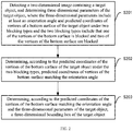
- FIG. 2 is a flowchart illustrating a three-dimensional object detecting method according to a first embodiment of the present application. As shown in FIG. 2 , specific steps of the method are as follows: Step S201, detecting a two-dimensional image containing a target object, and determining three-dimensional parameters of the target object, where the three-dimensional parameters include at least an orientation angle and predicted coordinates of vertices of a bottom surface of the target object under two blocking types where the two blocking types include that one of the vertices of the bottom surface is blocked and two of the vertices of the bottom surface are blocked.
- the image to be detected may be a two-dimensional image collected in scenarios such as intelligent information control, vehicle-road collaboration, auxiliary driving, and monitoring systems.
- the two-dimensional image contains at least one object, where one or more objects may be used as a target object for three-dimensional object detection, to determine a three-dimensional bounding box of the target object.
- the three-dimensional bounding box of the object includes 4 vertices of a top surface and 4 vertices of a bottom surface.
- two different blocking types may be determined according to a blocking relationship of the 4 vertices of the bottom surface.
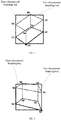
- the two blocking types include that one of the vertices of the bottom surface is blocked (as shown in FIG. 3 ) and two of the vertices of the bottom surface are blocked (as shown in FIG. 4 ). If one of the 4 vertices of the bottom surface of an object is blocked, the object corresponds to the type where one of vertices of the bottom surface is blocked. If two of the 4 vertices of the bottom surface of an object are blocked, the object corresponds to the type where two of vertices of the bottom surface are blocked.
- FIG. 3 shows a schematic diagram illustrating that one of vertices of the bottom surface is blocked.
- the three-dimensional bounding box includes 8 vertices numbered as (1) to (8), where 4 vertices numbered as (1) to (4) are vertices of the bottom surface and 4 vertices numbered as (5) to (8) are vertices of the top surface; among the 4 vertices of the bottom surface, only the vertex numbered as (4) is blocked.
- FIG. 4 shows a schematic diagram illustrating that two of vertices of the bottom surface are blocked.
- the three-dimensional bounding box includes 8 vertices numbered as (1) to (8), where 4 vertices numbered as (1) to (4) are vertices of the bottom surface and 4 vertices numbered as (5) to (8) are vertices of the top surface; among the 4 vertices of the bottom surface, the vertices numbered as (3) and (4) are blocked.
- the three-dimensional parameters of the target object refer to parameters required to determine the three-dimensional bounding box of the target object.
- the three-dimensional parameters of the target object include at least an orientation angle of the target object and predicted coordinates of vertices of the bottom surface of the target object under the two blocking types, and may also include a length, a width, and a height of the target object, etc.
- Step S202 determining, according to the predicted coordinates of the vertices of the bottom surface of the target object under the two blocking types, predicted coordinates of vertices of the bottom surface matching the orientation angle.
- predicted coordinates of vertices of the bottom surface matching the orientation angle are determined according to consistency between the orientation angle of the target object and the orientation angle predicted value calculated by the predicted coordinates of the vertices of the bottom surface of the target object under the two blocking types.
- Step S203 determining, according to the predicted coordinates of the vertices of the bottom surface matching the orientation angle and the three-dimensional parameters of the target object, a three-dimensional bounding box of the target object.
- the predicted coordinates of the vertices of the bottom surface matching the orientation angle are used as coordinates of the vertices of the bottom surface of the target object.
- the three-dimensional bounding box of the target object can be uniquely determined according to the coordinates of the vertices of the bottom surface of the target object as well as the length, the width and the height of the target object, etc.
- accuracy and robustness of the three-dimensional object detection can be effectively improved by: detecting an orientation angle and other parameters of a target object; predicting predicted coordinates of vertices of a bottom surface of the target object respectively under two blocking types; accurately determining a corresponding blocking type of the target object by selecting, based on the orientation angle of the target object, predicted coordinates of vertices of the bottom surface matching the orientation angle; using the predicted coordinates of the vertices of the bottom surface of the target object under the corresponding blocking type as coordinates of the vertices of the bottom surface of the target object; and determining a three-dimensional bounding box of the target object according to the predicted coordinates of the vertices of the bottom surface matching the orientation angle and the three-dimensional parameters of the target object.
- FIG. 5 is a flowchart illustrating a three-dimensional object detecting method according to a second embodiment of the present application.
- the two-dimensional image is input to a three-dimensional detection model, and the two-dimensional image containing the target object is detected through the three-dimensional detection model to determine the three-dimensional parameters of the target object.
- the three-dimensional parameters include the orientation angle, the predicted coordinates of the vertices of the bottom surface of the target object under the two blocking types, and a probability that the target object belongs to each blocking type.
- predicted coordinates of vertices of the bottom surface of the target object under a blocking type with a higher probability are used as the predicted coordinates of the vertices of the bottom surface matching the orientation angle. If the probability difference is less than the preset threshold, the predicted coordinates of the vertices of the bottom surface matching the orientation angle are determined according to the predicted coordinates of the vertices of the bottom surface of the target object under the two blocking types.
- the predicted coordinates of the vertices of the bottom surface matching the orientation angle may be used as coordinates of the vertices of the bottom surface of the target object, improving accuracy of the coordinates of the vertices of the bottom surface of the target object.
- Step S501 inputting a two-dimensional image into a three-dimensional detection model, and detecting the two-dimensional image containing a target object through the three-dimensional detection model to determine the three-dimensional parameter of the target object.
- the three-dimensional parameters of the target object refer to parameters required to determine the three-dimensional bounding box of the target object.
- the three-dimensional parameters may include an orientation angle, a length, a width, a height, predicted coordinates of vertices of a bottom surface of the target object under the two blocking types, and a probability that the target object belongs to each blocking type.
- a pre-trained neural network model may be used to detect the three-dimensional parameters of the target object in the two-dimensional image.
- the two-dimensional image is input into the neural network model, and parameters such as the orientation angle, the length, the width and the height of the target object, the predicted coordinates of the vertices of the bottom surface of the target object under the two blocking types and the probability that the target object belongs to each blocking type, are determined and output by the neural network model.
- the neural network model may use a two-stage 2D (two-dimensional) detection framework, such as R-CNN (Region-based Convolutional Neural Networks), or Faster R-CNN (Faster Region-based Convolutional Neural Networks), etc.
- the neural network model includes outputting at two stages: at a first stage, outputting a two-dimensional bounding box of the target object in the two-dimensional image; and at a second stage, outputting three-dimensional parameters such as the orientation angle, the length, the width and the height of the target object, the predicted coordinates of the vertices of the bottom surface of the target object under the two blocking types and the probability that the target object belongs to each blocking type.
- a training set is first acquired, where the training set includes multiple sample images and marked information of target objects in the sample images.
- the marked information includes information on a two-dimensional bounding box of the target object, coordinates of four vertices of a bottom surface of a three-dimensional bounding box, a corresponding blocking type of the target object, and an orientation angle, a length, a width and a height of the target object, etc.
- a predicted true value is acquired based on constraints of the two-dimensional bounding box, and corresponding marked information is determined.
- angle of view of a camera slopes downward.
- a corresponding blocking type of the target object, and the orientation angle, the length, the width, and the height of the target object, etc. may be marked and determined in advance.
- Coordinates of 8 vertices of the three-dimensional bounding box of the target object in a camera coordinate system may be pre-marked, and for example, can be detected and determined with other sensor.
- Coordinates of 4 vertices of the bottom surface of the three-dimensional bounding box of the target object in the sample image can be obtained by projecting the coordinates of the 4 vertices of the bottom surface of the three-dimensional bounding box of the target object in the camera coordinate system into the two-dimensional image.
- Coordinates of projection points of 4 vertices of the bottom surface of the three-dimensional bounding box of the target object on the sample image can be used as the coordinates of the 4 vertices of the bottom surface of the target object.
- the neural network model is trained based on the training set, and the trained neural network model is used as a final three-dimensional detection model.
- the two-dimensional image to be detected is input into a three-dimensional detection model, and the three-dimensional detection model is used to detect the two-dimensional image containing the target object to obtain parameters such as the orientation angle, the length, the width and the height of the target object, the predicted coordinates of the vertices of the bottom surface of the target object under the two blocking types and the probability that the target object belongs to each blocking type.
- the three-dimensional detection model may also be used to output a two-dimensional bounding box of the target object.
- Step S502 determining, according to the probability that the target object belongs to each blocking type among the three-dimensional parameters, a probability difference between probabilities that the target object belongs to the two blocking types.
- a probability difference between probabilities that the target object belongs to the two blocking types is calculated according to the probability that the target object belongs to each blocking type.
- the target object may be a vehicle, and if it is detected that a probability that the vehicle in the two-dimensional image belongs to one blocking type is PI and a probability that the vehicle belongs to the other blocking type is P2, then, in this step, the probability difference between the probabilities that the vehicle belongs to the two different blocking types may be:
- Step S503 determining whether the probability difference is less than a preset threshold.
- the blocking type to which the target object belongs and which is predicted by the three-dimensional detection model may be classified incorrectly, which results in large errors in the coordinates of the vertices of the bottom surface of the target object.
- prediction results of the three-dimensional detection model are not directly used; instead, based on probabilities that the target object belongs to the two blocking types, when it is determined that the prediction results has a low confidence, the blocking type to which the target object belongs is determined according to consistency between the orientation angle estimated by the predicted coordinates of the vertices of the bottom surface under the two blocking types and the orientation angle outputted by the three-dimensional detection model.
- Step S504 is executed, using predicted coordinates of vertices of the bottom surface of the target object under a blocking type with a higher probability as the predicted coordinates of the vertices of the bottom surface matching the orientation angle, so that a corresponding blocking type of the target object can be accurately determined.
- Steps S505-S507 are executed, determining, according to the predicted coordinates of the vertices of the bottom surface of the target object under the two blocking types, the predicted coordinates of vertices of the bottom surface matching the orientation angle.
- Step S504 using predicted coordinates of vertices of the bottom surface of the target object under a blocking type with a higher probability as the predicted coordinates of vertices of the bottom surface matching the orientation angle.
- Step S504 is executed, using the predicted coordinates of the vertices of the bottom surface of the target object under the blocking type with a higher probability as the predicted coordinates of the vertices of the bottom surface matching the orientation angle, so that a corresponding blocking type of the target object can be accurately determined.
- Step S505 calculating, according to the predicted coordinates of the vertices of the bottom surface of the target object under the two blocking types, orientation angle predicted values of the target object under the two blocking types.
- Steps S505-S507 are executed, determining, according to the predicted coordinates of the vertices of the bottom surface of the target object under the two blocking types, the predicted coordinates of the vertices of the bottom surface matching the orientation angle so as to further accurately determine a blocking type to which the target object corresponds so that the predicted coordinates of the vertices of the bottom surface of the target object under a corresponding blocking type are used as the coordinates of the vertices of the bottom surface of the target object, which improves accuracy of the coordinates of the vertices of the bottom surface of the target object.
- this step may be specifically implemented by: for any one of the blocking types, converting, according to predicted coordinates of vertices of the bottom surface of the target object under the blocking type and a camera parameter, the predicted coordinates of the vertices of the bottom surface into a camera coordinate system, and adding depth information to obtain predicted three-dimensional coordinates of the vertices of the bottom surface of the target object in the camera coordinate system; determining, according to the predicted three-dimensional coordinates of the vertices of the bottom surface of the target object, a quadrilateral formed by the vertices of the bottom surface; calculating orientation angle predicted values respectively corresponding to two adjacent sides of the quadrilateral; determining, in the orientation angle predicted values respectively corresponding to the two adjacent sides, an orientation angle predicted value having a smaller deviation from the orientation angle; and using the orientation angle predicted value having the smaller deviation from the orientation angle as the orientation angle predicted value of the target object under the blocking type.
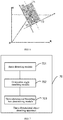
- ry 12 , ry 23 are both limited in a range of [- ⁇ , ⁇ ], and the orientation angle of the target object outputted by the three-dimensional detection model is also is the range of [ ⁇ , ⁇ ].
- the orientation angle predicted values corresponding to the two sides are determined, the one (Ry as shown in FIG. 6 , possibly ry 12 or ry 23 ) that is closer to the orientation angle of the target object outputted by the three-dimensional detection model is selected from them, that is, an orientation angle predicted value having a smaller deviation from the orientation angle is selected, to be used as the orientation angle predicted value of the target object under the blocking type, and in this way, the orientation angle predicted value of the target object under any one of the blocking types can be accurately determined.
- Step S506 calculating deviation angles between the orientation angle predicted values of the target object under the two blocking types and the orientation angle.
- Step S507 using predicted coordinates of vertices of the bottom surface of the target object under a blocking type with a smaller deviation angle as the predicted coordinates of the vertices of the bottom surface matching the orientation angle.
- the deviation angle between the orientation angle predicted value of the target object and the orientation angle is smaller, it means that the orientation angle predicted value of the target object under a corresponding blocking type is more consistent with the orientation angle of the target object outputted by the three-dimensional detection model, and the predicted coordinates of the vertices of the bottom surface of the target object under the corresponding blocking type have a higher matching degree with the orientation angle of the target object. Therefore, the predicted coordinates of the vertices of the bottom surface of the target object under the blocking type with a smaller deviation angle are used as the predicted coordinates of the vertices of the bottom surface matching the orientation angle.
- the predicted coordinates of the vertices of the bottom surface matching the orientation angle are determined, it is possible to uniquely determine, based on the predicted coordinates of 4 vertices of the bottom surface in combination with the length, the width and the height of the target object, the three-dimensional bounding box of the target object.
- Steps S508-S510 are used to determine the three-dimensional bounding box of the target object according to the predicted coordinates of the vertices of the bottom surface matching the orientation angle together and the three-dimensional parameters of the target object so that the three-dimensional bounding box of the target object can be accurately determined.
- Step S508 determining coordinates of a center point of the bottom surface of the target object according to the predicted coordinates of the vertices of the bottom surface matching the orientation angle.
- the predicted coordinates of the vertices of the bottom surface matching the orientation angle may be used as coordinates of the vertices of the bottom surface of the target object, and the coordinates of the center point of the bottom surface of the target object are determined according to the predicted coordinates of the vertices of the bottom surface matching the orientation angle.
- This step may be specifically implemented by: converting, according to a ground equation and a camera parameter, the predicted coordinates of the vertices of the bottom surface matching the orientation angle into a ground coordinate system to obtain three-dimensional coordinates of the vertices of the bottom surface of the target object in the ground coordinate system; and determining the coordinates of the center point of the bottom surface of the target object according to the three-dimensional coordinates of the vertices of the bottom surface of the target object in the ground coordinate system.
- the converting, according to the ground equation and the camera parameter, the predicted coordinates of the vertices of the bottom surface matching the orientation angle into the ground coordinate system to obtain the three-dimensional coordinates of the vertices of the bottom surface of the target object in the ground coordinate system may be implemented by: converting, according to the predicted coordinates of the vertices of the bottom surface matching the orientation angle and the camera parameter, the predicted coordinates of the vertices of the bottom surface matching the orientation angle into a camera coordinate system, and adding depth information to obtain three-dimensional coordinates of the vertices of the bottom surface of the target object in the camera coordinate system; determining a transformation matrix from the camera coordinate system to the ground coordinate system according to the ground equation; and determining the three-dimensional coordinates of the vertices of the bottom surface of the target object in the ground coordinate system according to the three-dimensional coordinates of the vertices of the bottom surface of the target object in the camera coordinate system and the transformation matrix.
- Step S505 during the process of calculating the orientation angle predicted values of the target object under the two blocking types, according to the predicted coordinates of the vertices of the bottom surface of the target object under the blocking type and the camera parameter, the predicted coordinates of the vertices of the bottom surface are converted into the camera coordinate system, and depth information is added, to obtain predicted three-dimensional coordinates of the vertices of the bottom surface of the target object in the camera coordinate system.
- a transformation matrix from the camera to the ground may be first obtained according to the ground equation, then the predicted three-dimensional coordinates of the vertices of the bottom surface of the target object in the camera coordinate system are converted into a ground coordinate system according to the transformation matrix to obtain three-dimensional coordinates of the vertices of the bottom surface of the target object in the ground coordinate system; further, the coordinates of the center point of the bottom surface of the target object are determined according to the three-dimensional coordinates of the vertices of the bottom surface of the target object in the ground coordinate system, so that the three-dimensional coordinates of the vertices of the bottom surface of the target object in the ground coordinate system can be determined based on the two-dimensional predicted coordinates of the vertices of the bottom surface of the target object output by the three-dimensional detection model.
- the transformation matrix from the camera to the ground being first obtained according to the ground equation may be specifically implemented in the following manner:
- Step S509 determining coordinates of a center point of the target object according to a height of the target object and the coordinates of the center point of the bottom surface.
- the three-dimensional parameters further include: a length, a height and a width of the target object.
- the center point of the bottom surface of the target object may be fused with size information such as the length, the width and the height to restore the center point of the three-dimensional bounding box of the target object, that is, determine the coordinates of the center point of the target object.
- Step S510 determining the three-dimensional bounding box of the target object according to the coordinates of the center point of the target object and the orientation angle, the length, the width and the height of the target object.
- the three-dimensional bounding box of the target object may be uniquely determined in combination with the length, the width, and the height of the target object.
- the embodiment of the present application involves: predicting, based on two different blocking types, predicted coordinates of vertices of a bottom surface of a target object under different blocking types and probabilities that the target object belongs to the two different blocking types, respectively; and based on a difference between the probabilities that the target object belongs to the different blocking types and when prediction results has low confidence, the blocking type to which the target object belongs is further determined according to consistency between the orientation angle estimated by the predicted coordinates of the vertices of the bottom surface under the two blocking types and the orientation angle outputted by the three-dimensional detection model so that a corresponding blocking type of the target object can be determined accurately; and using the predicted coordinates of the vertices of the bottom surface under the corresponding blocking type as coordinates of the vertices of the bottom surface of the target object so that accuracy of the coordinates of the vertices of the bottom surface of the target object is improved; and then determining a three-dimensional bounding box of the target object based on the coordinates of the vertices of the bottom surface of the
- FIG. 7 is a schematic diagram illustrating a three-dimensional object detecting apparatus according to a third embodiment of the present application.
- the three-dimensional object detecting apparatus according to the embodiment of the present application may execute processing flows provided in the embodiment of the three-dimensional object detecting method.
- the three-dimensional object detecting apparatus 70 includes: a basic detecting module 701, an orientation angle matching module 702 and a three-dimensional bounding box determining module 703.
- the basic detecting module 701 is configured to detect a two-dimensional image containing a target object, and determine a three-dimensional parameters of the target object, where the three-dimensional parameters include at least an orientation angle and predicted coordinates of vertices of a bottom surface of the target object under two blocking types, where the two blocking types include that one of vertices of the bottom surface is blocked and two of the vertices of the bottom surface are blocked.
- the orientation angle matching module 702 is configured to determine, according to the predicted coordinates of the vertices of the bottom surface of the target object under the two blocking types, predicted coordinates of vertices of the bottom surface matching the orientation angle.
- the three-dimensional bounding box determining module 703 is configured to determine, according to the predicted coordinates of the vertices of the bottom surface matching the orientation angle and the three-dimensional parameters of the target object, a three-dimensional bounding box of the target object.
- the apparatus provided in the embodiment of the present application may be specifically configured to execute the method embodiment provided in the first embodiment described above, and specific functions will not be described here again.
- the embodiment of the present application involves: detecting an orientation angle and other parameters of a target object; predicting predicted coordinates of vertices of a bottom surface of the target object respectively under two blocking types; selecting predicted coordinates of vertices of the bottom surface matching the orientation angle based on the orientation angle of the target object, thereby accurately determining a corresponding blocking type of the target object; using the predicted coordinates of the vertices of the bottom surface of the target object under the corresponding blocking type as coordinates of the vertices of the bottom surface of the target object; and determining a three-dimensional bounding box of the target object according to the predicted coordinates of the vertices of the bottom surface matching the orientation angle and the three-dimensional parameters of the target object. Therefore, accuracy and robustness of the three-dimensional object detection can be effectively improved.
- the three-dimensional parameters further include a probability that the target object belongs to each blocking type.
- the basic detecting module is further configured to determine a probability difference between probabilities that the target object belongs to the two blocking types.
- the orientation angle matching module is further configured to, if the probability difference is greater than or equal to a preset threshold, use predicted coordinates of vertices of the bottom surface of the target object under a blocking type with a higher probability as the predicted coordinates of the vertices of the bottom surface matching the orientation angle.
- the basic detecting module is further configured to: input a two-dimensional image into a three-dimensional detection model, and detect the two-dimensional image containing the target object through the three-dimensional detection model, to determine the three-dimensional parameters of the target object.
- the orientation angle matching module is further configured to: if the probability difference is less than the preset threshold, determine, according to the predicted coordinates of the vertices of the bottom surface of the target object under the two blocking types, the predicted coordinates of the vertices of the bottom surface matching the orientation angle.
- the orientation angle matching module is further configured to: calculate, according to the predicted coordinates of the vertices of the bottom surface of the target object under the two blocking types, orientation angle predicted values of the target object under the two blocking types; calculate deviation angles between the orientation angle predicted values of the target object under the two blocking types and the orientation angle; and use predicted coordinates of vertices of the bottom surface of the target object under a blocking type with a smaller deviation angle as the predicted coordinates of the vertices of the bottom surface matching the orientation angle.
- the orientation angle matching module is further configured to: for any one of the blocking types, convert, according to predicted coordinates of vertices of the bottom surface of the target object under the blocking type and a camera parameter, the predicted coordinates of the vertices of the bottom surface into a camera coordinate system, and add depth information to obtain predicted three-dimensional coordinates of the vertices of the bottom surface of the target object in the camera coordinate system; determine, according to the predicted three-dimensional coordinates of the vertices of the bottom surface of the target object, a quadrilateral formed by the vertices of the bottom surface; calculate orientation angle predicted values respectively corresponding to two adjacent sides of the quadrilateral; determine, in the orientation angle predicted values respectively corresponding to the two adjacent sides, an orientation angle predicted value having a smaller deviation from the orientation angle; and use the orientation angle predicted value having the smaller deviation from the orientation angle as the orientation angle predicted value of the target object under the blocking type.
- the three-dimensional parameters further include: a length, a height and a width of the target object.
- the three-dimensional bounding box determining module is further configured to: determine coordinates of a center point of the bottom surface of the target object according to the predicted coordinates of the vertices of the bottom surface matching the orientation angle; determine coordinates of a center point of the target object according to the height of the target object and the coordinates of the center point of the bottom surface; and determine the three-dimensional bounding box of the target object according to the coordinates of the center point of the target object as well as the orientation angle, the length, the width and the height of the target object.
- the three-dimensional bounding box determining module is further configured to: convert, according to a ground equation and a camera parameter, the predicted coordinates of the vertices of the bottom surface matching the orientation angle into a ground coordinate system to obtain three-dimensional coordinates of the vertices of the bottom surface of the target object in the ground coordinate system; and determine the coordinates of the center point of the bottom surface of the target object according to the three-dimensional coordinates of the vertices of the bottom surface of the target object in the ground coordinate system.
- the three-dimensional bounding box determining module is further configured to: convert, according to the predicted coordinates of the vertices of the bottom surface matching the orientation angle and the camera parameter, the predicted coordinates of the vertices of the bottom surface matching the orientation angle into the camera coordinate system, and add depth information to obtain three-dimensional coordinates of the vertices of the bottom surface of the target object in the camera coordinate system; determine a transformation matrix from the camera coordinate system to the ground coordinate system according to the ground equation; and determine the three-dimensional coordinates of the vertices of the bottom surface of the target object in the ground coordinate system according to the three-dimensional coordinates of the vertices of the bottom surface of the target object in the camera coordinate system and the transformation matrix.
- the apparatus provided in the embodiment of the present application may be specifically configured to execute the method embodiment provided in the second embodiment described above, and specific functions will not be described here again.
- the embodiment of the present application involves: predicting, based on two different blocking types, predicted coordinates of vertices of a bottom surface of a target object under different blocking types and probabilities that the target object belongs to the two different blocking types, respectively; based on a difference between the probabilities that the target object belongs to the different blocking types and when prediction results have low confidence, further determining the blocking type to which the target object belongs according to consistency between the orientation angle estimated by the predicted coordinates of the vertices of the bottom surface under the two blocking types and the orientation angle outputted by the three-dimensional detection model, so that a corresponding blocking type of the target object can be determined accurately; and using the predicted coordinates of the vertices of the bottom surface under the corresponding blocking type as coordinates of the vertices of the bottom surface of the target object so that accuracy of the coordinates of the vertices of the bottom surface of the target object is improved; and then determining a three-dimensional bounding box of the target object based on the coordinates of the vertices of the bottom surface of the
- the present application also provides an electronic device and a readable storage medium.
- the present application also provides a computer program product, where the program product includes a computer program stored in a readable storage medium, at least one processor of the electronic device may read a computer program from the readable medium storage, and the at least one processor executes the computer program to enable the electronic device to execute the solution provided in any of the foregoing embodiments.
- FIG. 8 shows a schematic block diagram of an exemplary electronic device 800 which can be used to implement an embodiment of the present application.
- the electronic device is intended to represent various forms of digital computers, such as a laptop computer, a desktop computer, a workstation, a personal digital assistant, a server, a blade server, a mainframe computer, and other suitable computers.
- the electronic device can also represent various forms of mobile devices, such as a personal digital assistant, a cellular phone, a smart phone, a wearable device, and other similar computing apparatuses.
- the components shown herein, their connections and relationships, and their functions are merely exemplary, and are not intended to limit the implementation of the present disclosure described and/or required herein.
- the electronic device 800 includes a computing unit 801, which may perform various appropriate actions and processes according to a computer program stored in a read-only memory (ROM) 802 or a computer program loaded from a storage unit 808 into a random access memory (RAM) 803.
- ROM read-only memory
- RAM random access memory
- various programs and data required for operations of the device 800 may also be stored.
- the computing unit 801, the ROM 802, and the RAM 803 are connected to each other through a bus 804.
- An input/output (I/O) interface 805 is also connected to the bus 804.
- the components include: an input unit 806, such as a keyboard, a mouse, etc.; an output unit 807, such as various types of displays, speakers, etc.; the storage unit 808, such as a magnetic disk, an optical disc, etc.; and a communication unit 809, such as a network card, a modem, a wireless communication transceiver, etc.
- the communication unit 809 allows the device 800 to exchange information/data with other devices over a computer network such as Internet and/or various telecommunication networks.
- the computing unit 801 may be various general-purpose and/or special-purpose processing components with processing and computing capabilities. Some examples of the computing unit 801 include, but are not limited to, central processing units (CPU), graphics processing units (GPU), various general-purpose artificial intelligence (AI) computing chips, various computing units that run machine learning model algorithms, digital signal processors (DSP), and also any appropriate processors, controllers, microcontrollers, etc.
- the computing unit 801 executes each method and process described above, for example, the three-dimensional object detecting method.
- the three-dimensional object detecting method can be implemented as a computer software program, which is tangibly contained in a machine-readable medium, such as the storage unit 808.
- part or all of the computer program may be loaded and/or installed into the device 800 via the ROM 802 and/or the communication unit 809.
- the computer program When the computer program is loaded into the RAM 803 and executed by the computing unit 801, one or more steps of the three-dimensional object detecting method as described above may be executed.
- the computing unit 801 may be configured to perform the three-dimensional object detecting method in any other suitable manner (for example, by firmware).
- Various embodiments of the systems and technologies described herein may be implemented in a digital electronic circuit system, an integrated circuit system, a field programmable gate array (FPGA), an application-specific integrated circuit (ASIC), application specific standard parts (ASSP), a system-on-chip (SOC), a complex programmable logic device (CPLD), computer hardware, firmware, software, and/or their combination.
- FPGA field programmable gate array
- ASIC application-specific integrated circuit
- ASSP application specific standard parts
- SOC system-on-chip
- CPLD complex programmable logic device
- These various implementations may include: being implemented in one or more computer programs, where the one or more computer programs may be executed and/or interpreted on a programmable system including at least one programmable processor, and where the programmable processor may be a special-purpose or general-purpose programmable processor, can receive data and instructions from a storage system, at least one input apparatus, and at least one output apparatus, and transmit the data and instructions to the storage system, the at least one input apparatus, and the at least one output apparatus.
- Program codes for implementing the method of the present disclosure can be written in one programming language or any combination of programming languages. These program codes can be provided to a processor or a controller of a general-purpose computer, a special-purpose computer, or other programmable data processing apparatus, so that functions/operations specified in flowcharts and/or block diagrams are implemented when the program codes are executed by the processor or the controller.
- the program codes may be executed entirely and partly on a machine, partly executed on the machine and partly executed on a remote machine as an independent software package, or entirely executed on the remote machine or a server.
- the machine-readable medium may be a tangible medium, which may contain or store a program that can be used by an instruction executable system, apparatus, or device or can be used in combination with the instruction executable system, apparatus, or device.
- the machine-readable medium may be a machine-readable signal medium or a machine-readable storage medium.
- the machine-readable medium may include, but is not limited to, an electronic, magnetic, optical, electromagnetic, infrared, or semiconductor system, apparatus, or device, or any suitable combination of the foregoing.
- machine-readable storage media would include electrically connected portable computer disks based on one or more wires, hard disks, random access memories (RAM), read-only memories (ROM), erasable programmable read-only memories (EPROM or flash memories), optical fibers, portable compact disk read-only memories (CD-ROM), optical storage devices, magnetic storage devices, or any suitable combination of the foregoing.
- RAM random access memories
- ROM read-only memories
- EPROM or flash memories erasable programmable read-only memories
- CD-ROM portable compact disk read-only memories
- magnetic storage devices or any suitable combination of the foregoing.
- the systems and techniques described herein can be implemented on a computer, where the computer has: a display apparatus for displaying information to users (for example, a CRT (cathode ray tube) or an LCD (liquid crystal display) monitor); and a keyboard and a pointing device (for example, a mouse or trackball) through which the users can provide input to the computer.
- a display apparatus for displaying information to users
- a keyboard and a pointing device for example, a mouse or trackball
- Other types of apparatuses can also be used to provide interaction with the users; for example, the feedback provided to the users may be any form of sensory feedback (for example, visual feedback, auditory feedback, or tactile feedback); and input from the users can be received in any form (including acoustic input, voice input, or tactile input).
- the systems and technologies described herein can be implemented in a computing system that includes background components (for example, as a data server), or a computing system that includes middleware components (for example, an application server), or a computing system that includes front-end components (for example, a user computer with a graphical user interface or a web browser through which the user can interact with implementations of the systems and technologies described herein), or a computing system that includes any combination of such background components, middleware components, or front-end components.
- the components of the system can be connected to each other through any form or medium of digital data communication (for example, a communication network). Examples of communication networks include: local area networks (LAN), wide area networks (WAN) and Internet.
- the computing system may include a client and a server.
- the client and server are generally far away from each other and usually interact through a communication network.
- the relationship between the client and the server is generated through computer programs running on the corresponding computers and having a client-server relationship with each other.
- the server may be a cloud server, also known as a cloud computing server or a cloud host, which is a host product in a cloud computing service system to overcome defects of difficult management and weak business scalability existing in a traditional physical host and a VPS service ("Virtual Private Server", or "VPS" for short).
- the server may also be a server of a distributed system, or a server combined with a block-chain.
Landscapes
- Engineering & Computer Science (AREA)
- Physics & Mathematics (AREA)
- Theoretical Computer Science (AREA)
- General Physics & Mathematics (AREA)
- Data Mining & Analysis (AREA)
- Software Systems (AREA)
- Evolutionary Computation (AREA)
- Life Sciences & Earth Sciences (AREA)
- Artificial Intelligence (AREA)
- General Engineering & Computer Science (AREA)
- Computational Linguistics (AREA)
- General Health & Medical Sciences (AREA)
- Multimedia (AREA)
- Mathematical Physics (AREA)
- Computing Systems (AREA)
- Health & Medical Sciences (AREA)
- Biomedical Technology (AREA)
- Biophysics (AREA)
- Molecular Biology (AREA)
- Computer Graphics (AREA)
- Geometry (AREA)
- Computer Vision & Pattern Recognition (AREA)
- Bioinformatics & Cheminformatics (AREA)
- Bioinformatics & Computational Biology (AREA)
- Evolutionary Biology (AREA)
- Probability & Statistics with Applications (AREA)
- Image Analysis (AREA)
Applications Claiming Priority (1)
| Application Number | Priority Date | Filing Date | Title |
|---|---|---|---|
| CN202011507625.9A CN112509126B (zh) | 2020-12-18 | 2020-12-18 | 三维物体检测的方法、装置、设备及存储介质 |
Publications (2)
| Publication Number | Publication Date |
|---|---|
| EP3905124A2 true EP3905124A2 (de) | 2021-11-03 |
| EP3905124A3 EP3905124A3 (de) | 2022-01-05 |
Family
ID=74922583
Family Applications (1)
| Application Number | Title | Priority Date | Filing Date |
|---|---|---|---|
| EP21179067.0A Withdrawn EP3905124A3 (de) | 2020-12-18 | 2021-06-11 | Verfahren zur detektion eines dreidimensionalen objekts, einrichtung, vorrichtung und speichermedium |
Country Status (3)
| Country | Link |
|---|---|
| US (1) | US20210295013A1 (de) |
| EP (1) | EP3905124A3 (de) |
| CN (1) | CN112509126B (de) |
Families Citing this family (6)
| Publication number | Priority date | Publication date | Assignee | Title |
|---|---|---|---|---|
| US11987236B2 (en) * | 2020-08-31 | 2024-05-21 | Nec Corporation | Monocular 3D object localization from temporal aggregation |
| CN114332751B (zh) * | 2021-11-24 | 2025-07-18 | 上海智能网联汽车技术中心有限公司 | 一种基于交通监控摄像的目标检测和跟踪定位方法 |
| CN114299470B (zh) * | 2021-12-31 | 2026-02-03 | 智道网联科技(北京)有限公司 | 基于中心点约束的路牌角点识别方法及装置 |
| CN114419519B (zh) * | 2022-03-25 | 2022-06-24 | 北京百度网讯科技有限公司 | 目标对象检测方法、装置、电子设备和存储介质 |
| CN115583192B (zh) * | 2022-09-30 | 2024-01-30 | 深圳市欧冶半导体有限公司 | 一种智能远光灯的控制方法及相关装置 |
| CN116823907A (zh) * | 2023-05-18 | 2023-09-29 | 嬴彻星创智能科技(上海)有限公司 | 截断目标物体深度预测方法及装置 |
Family Cites Families (26)
| Publication number | Priority date | Publication date | Assignee | Title |
|---|---|---|---|---|
| US6873998B1 (en) * | 2000-10-18 | 2005-03-29 | Navteq North America, Llc | System and method for updating a geographic database using satellite imagery |
| JP2007014476A (ja) * | 2005-07-06 | 2007-01-25 | Circle Wave:Kk | 立体盤面ゲームプログラムおよび立体盤面ゲーム器具 |
| KR20090130701A (ko) * | 2008-06-16 | 2009-12-24 | 삼성전자주식회사 | 반도체 패키지 및 그의 제조 방법 |
| CN108780576B (zh) * | 2016-04-06 | 2022-02-25 | 赫尔实验室有限公司 | 使用对象边界框的视频片段中的重影去除的系统和方法 |
| US10509947B1 (en) * | 2017-04-11 | 2019-12-17 | Zoox, Inc. | Converting multi-dimensional data for image analysis |
| CN107730503B (zh) * | 2017-09-12 | 2020-05-26 | 北京航空航天大学 | 三维特征嵌入的图像对象部件级语义分割方法与装置 |
| US10438371B2 (en) * | 2017-09-22 | 2019-10-08 | Zoox, Inc. | Three-dimensional bounding box from two-dimensional image and point cloud data |
| US10402724B2 (en) * | 2017-10-03 | 2019-09-03 | StradVision, Inc. | Method for acquiring a pseudo-3D box from a 2D bounding box by regression analysis and learning device and testing device using the same |
| US11062461B2 (en) * | 2017-11-16 | 2021-07-13 | Zoox, Inc. | Pose determination from contact points |
| CN108549084B (zh) * | 2018-01-30 | 2020-06-02 | 西安交通大学 | 一种基于稀疏二维激光雷达的目标检测与姿态估计方法 |
| US11618438B2 (en) * | 2018-03-26 | 2023-04-04 | International Business Machines Corporation | Three-dimensional object localization for obstacle avoidance using one-shot convolutional neural network |
| US10816992B2 (en) * | 2018-04-17 | 2020-10-27 | Baidu Usa Llc | Method for transforming 2D bounding boxes of objects into 3D positions for autonomous driving vehicles (ADVs) |
| US10817752B2 (en) * | 2018-05-31 | 2020-10-27 | Toyota Research Institute, Inc. | Virtually boosted training |
| CN110815202B (zh) * | 2018-08-07 | 2021-11-09 | 杭州海康机器人技术有限公司 | 障碍物检测方法及装置 |
| US10839234B2 (en) * | 2018-09-12 | 2020-11-17 | Tusimple, Inc. | System and method for three-dimensional (3D) object detection |
| US10818078B2 (en) * | 2018-09-25 | 2020-10-27 | Sony Corporation | Reconstruction and detection of occluded portions of 3D human body model using depth data from single viewpoint |
| KR102723996B1 (ko) * | 2018-11-01 | 2024-10-30 | 삼성전자주식회사 | 2차원 영상으로부터 3차원 객체를 검출하는 방법 및 장치 |
| EP3703008A1 (de) * | 2019-02-26 | 2020-09-02 | Zenuity AB | Objekterkennung und 3d-box-fitting |
| CN112017239B (zh) * | 2019-05-31 | 2022-12-20 | 北京市商汤科技开发有限公司 | 确定目标对象朝向方法、智能驾驶控制方法和装置及设备 |
| CN110222764B (zh) * | 2019-06-10 | 2021-06-18 | 中南民族大学 | 遮挡目标检测方法、系统、设备及存储介质 |
| US11321872B2 (en) * | 2019-07-19 | 2022-05-03 | Avigilon Corporation | Method for calibrating a camera using bounding boxes, and camera configured to perform that method |
| US11074438B2 (en) * | 2019-10-01 | 2021-07-27 | Toyota Research Institute, Inc. | Disentangling human dynamics for pedestrian locomotion forecasting with noisy supervision |
| CN110826499A (zh) * | 2019-11-08 | 2020-02-21 | 上海眼控科技股份有限公司 | 物体空间参数检测方法、装置、电子设备及存储介质 |
| CN110929639B (zh) * | 2019-11-20 | 2023-09-19 | 北京百度网讯科技有限公司 | 用于确定图像中障碍物位置的方法、装置、设备和介质 |
| CN111079619B (zh) * | 2019-12-10 | 2023-04-18 | 北京百度网讯科技有限公司 | 用于检测图像中的目标对象的方法和装置 |
| CN111612753B (zh) * | 2020-05-15 | 2021-08-06 | 北京百度网讯科技有限公司 | 三维物体检测方法、装置、电子设备和可读存储介质 |
-
2020
- 2020-12-18 CN CN202011507625.9A patent/CN112509126B/zh active Active
-
2021
- 2021-06-07 US US17/340,809 patent/US20210295013A1/en not_active Abandoned
- 2021-06-11 EP EP21179067.0A patent/EP3905124A3/de not_active Withdrawn
Also Published As
| Publication number | Publication date |
|---|---|
| US20210295013A1 (en) | 2021-09-23 |
| CN112509126A (zh) | 2021-03-16 |
| EP3905124A3 (de) | 2022-01-05 |
| CN112509126B (zh) | 2024-07-12 |
Similar Documents
| Publication | Publication Date | Title |
|---|---|---|
| EP3905124A2 (de) | Verfahren zur detektion eines dreidimensionalen objekts, einrichtung, vorrichtung und speichermedium | |
| CN113902897B (zh) | 目标检测模型的训练、目标检测方法、装置、设备和介质 | |
| US11688099B2 (en) | Method and apparatus for detecting obstacle | |
| US20220222951A1 (en) | 3d object detection method, model training method, relevant devices and electronic apparatus | |
| EP3937077B1 (de) | Fahrbahnmarkierungserkennungsverfahren, gerät, elektronische vorrichtung, speichermedium und fahrzeug | |
| EP3968266B1 (de) | Verfahren und vorrichtung zur dreidimensionalen positionserfassung von hindernissen für eine vorrichtung zur strassenseitigen datenverarbeitung | |
| US12430928B2 (en) | Positioning method based on lane line and feature point, electronic device, and storage medium | |
| EP3989117A1 (de) | Verfahren und vorrichtung zur erkennung von fahrzeuginformationen, verfahren und vorrichtung zum trainieren eines erkennungsmodells, elektronische vorrichtung, speichermedium und programm | |
| US20210209341A1 (en) | Three-dimensional object detection method, electronic device and readable storage medium | |
| US20220351398A1 (en) | Depth detection method, method for training depth estimation branch network, electronic device, and storage medium | |
| CN117746133B (zh) | 目标检测方法、模型训练方法、装置、设备及存储介质 | |
| CN115719436A (zh) | 模型训练方法、目标检测方法、装置、设备以及存储介质 | |
| CN113378693B (zh) | 生成目标检测系统和检测目标的方法及装置 | |
| US20230162383A1 (en) | Method of processing image, device, and storage medium | |
| WO2022237821A1 (zh) | 生成交通标志线地图的方法、设备和存储介质 | |
| EP4207072A1 (de) | Verfahren zur verstärkung dreidimensionaler daten, modelltrainings- und -detektionsverfahren, vorrichtung und autonomes fahrzeug | |
| CN115147809B (zh) | 一种障碍物检测方法、装置、设备以及存储介质 | |
| CN115861400B (zh) | 目标对象检测方法、训练方法、装置以及电子设备 | |
| CN115139303A (zh) | 一种栅格井盖检测方法、装置、设备及存储介质 | |
| CN113762397A (zh) | 检测模型训练、高精度地图更新方法、设备、介质及产品 | |
| CN114495042B (zh) | 目标检测方法和装置 | |
| CN116343152A (zh) | 车道线检测方法、装置及电子设备 | |
| CN118537834A (zh) | 车辆感知信息获取方法、装置、设备及存储介质 | |
| CN113378694B (zh) | 生成目标检测和定位系统及目标检测和定位的方法及装置 | |
| US20220207991A1 (en) | Method and device for determining boundary points of bottom surface of vehicle, roadside device and cloud control platform |
Legal Events
| Date | Code | Title | Description |
|---|---|---|---|
| PUAI | Public reference made under article 153(3) epc to a published international application that has entered the european phase |
Free format text: ORIGINAL CODE: 0009012 |
|
| STAA | Information on the status of an ep patent application or granted ep patent |
Free format text: STATUS: REQUEST FOR EXAMINATION WAS MADE |
|
| 17P | Request for examination filed |
Effective date: 20210611 |
|
| AK | Designated contracting states |
Kind code of ref document: A2 Designated state(s): AL AT BE BG CH CY CZ DE DK EE ES FI FR GB GR HR HU IE IS IT LI LT LU LV MC MK MT NL NO PL PT RO RS SE SI SK SM TR |
|
| PUAL | Search report despatched |
Free format text: ORIGINAL CODE: 0009013 |
|
| AK | Designated contracting states |
Kind code of ref document: A3 Designated state(s): AL AT BE BG CH CY CZ DE DK EE ES FI FR GB GR HR HU IE IS IT LI LT LU LV MC MK MT NL NO PL PT RO RS SE SI SK SM TR |
|
| RIC1 | Information provided on ipc code assigned before grant |
Ipc: G06K 9/00 20060101AFI20211130BHEP |
|
| STAA | Information on the status of an ep patent application or granted ep patent |
Free format text: STATUS: EXAMINATION IS IN PROGRESS |
|
| 17Q | First examination report despatched |
Effective date: 20240112 |
|
| STAA | Information on the status of an ep patent application or granted ep patent |
Free format text: STATUS: THE APPLICATION HAS BEEN WITHDRAWN |
|
| 18W | Application withdrawn |
Effective date: 20240318 |