EP3905001A1 - Mobile terminal and antenna control method - Google Patents
Mobile terminal and antenna control method Download PDFInfo
- Publication number
- EP3905001A1 EP3905001A1 EP19903852.2A EP19903852A EP3905001A1 EP 3905001 A1 EP3905001 A1 EP 3905001A1 EP 19903852 A EP19903852 A EP 19903852A EP 3905001 A1 EP3905001 A1 EP 3905001A1
- Authority
- EP
- European Patent Office
- Prior art keywords
- module
- mobile terminal
- radiation branch
- antenna radiation
- antenna
- Prior art date
- Legal status (The legal status is an assumption and is not a legal conclusion. Google has not performed a legal analysis and makes no representation as to the accuracy of the status listed.)
- Granted
Links
Images


Classifications
-
- G—PHYSICS
- G06—COMPUTING OR CALCULATING; COUNTING
- G06F—ELECTRIC DIGITAL DATA PROCESSING
- G06F1/00—Details not covered by groups G06F3/00 - G06F13/00 and G06F21/00
- G06F1/16—Constructional details or arrangements
- G06F1/1613—Constructional details or arrangements for portable computers
- G06F1/1633—Constructional details or arrangements of portable computers not specific to the type of enclosures covered by groups G06F1/1615 - G06F1/1626
- G06F1/1675—Miscellaneous details related to the relative movement between the different enclosures or enclosure parts
- G06F1/1677—Miscellaneous details related to the relative movement between the different enclosures or enclosure parts for detecting open or closed state or particular intermediate positions assumed by movable parts of the enclosure, e.g. detection of display lid position with respect to main body in a laptop, detection of opening of the cover of battery compartment
-
- H—ELECTRICITY
- H01—ELECTRIC ELEMENTS
- H01Q—ANTENNAS, i.e. RADIO AERIALS
- H01Q5/00—Arrangements for simultaneous operation of antennas on two or more different wavebands, e.g. dual-band or multi-band arrangements
- H01Q5/30—Arrangements for providing operation on different wavebands
- H01Q5/307—Individual or coupled radiating elements, each element being fed in an unspecified way
- H01Q5/342—Individual or coupled radiating elements, each element being fed in an unspecified way for different propagation modes
- H01Q5/35—Individual or coupled radiating elements, each element being fed in an unspecified way for different propagation modes using two or more simultaneously fed points
-
- G—PHYSICS
- G06—COMPUTING OR CALCULATING; COUNTING
- G06F—ELECTRIC DIGITAL DATA PROCESSING
- G06F1/00—Details not covered by groups G06F3/00 - G06F13/00 and G06F21/00
- G06F1/16—Constructional details or arrangements
- G06F1/1613—Constructional details or arrangements for portable computers
- G06F1/1615—Constructional details or arrangements for portable computers with several enclosures having relative motions, each enclosure supporting at least one I/O or computing function
- G06F1/1616—Constructional details or arrangements for portable computers with several enclosures having relative motions, each enclosure supporting at least one I/O or computing function with folding flat displays, e.g. laptop computers or notebooks having a clamshell configuration, with body parts pivoting to an open position around an axis parallel to the plane they define in closed position
-
- G—PHYSICS
- G06—COMPUTING OR CALCULATING; COUNTING
- G06F—ELECTRIC DIGITAL DATA PROCESSING
- G06F1/00—Details not covered by groups G06F3/00 - G06F13/00 and G06F21/00
- G06F1/16—Constructional details or arrangements
- G06F1/1613—Constructional details or arrangements for portable computers
- G06F1/1633—Constructional details or arrangements of portable computers not specific to the type of enclosures covered by groups G06F1/1615 - G06F1/1626
- G06F1/1684—Constructional details or arrangements related to integrated I/O peripherals not covered by groups G06F1/1635 - G06F1/1675
- G06F1/1698—Constructional details or arrangements related to integrated I/O peripherals not covered by groups G06F1/1635 - G06F1/1675 the I/O peripheral being a sending/receiving arrangement to establish a cordless communication link, e.g. radio or infrared link, integrated cellular phone
-
- H—ELECTRICITY
- H01—ELECTRIC ELEMENTS
- H01Q—ANTENNAS, i.e. RADIO AERIALS
- H01Q1/00—Details of, or arrangements associated with, antennas
- H01Q1/12—Supports; Mounting means
- H01Q1/22—Supports; Mounting means by structural association with other equipment or articles
- H01Q1/24—Supports; Mounting means by structural association with other equipment or articles with receiving set
- H01Q1/241—Supports; Mounting means by structural association with other equipment or articles with receiving set used in mobile communications, e.g. GSM
- H01Q1/242—Supports; Mounting means by structural association with other equipment or articles with receiving set used in mobile communications, e.g. GSM specially adapted for hand-held use
- H01Q1/243—Supports; Mounting means by structural association with other equipment or articles with receiving set used in mobile communications, e.g. GSM specially adapted for hand-held use with built-in antennas
-
- H—ELECTRICITY
- H01—ELECTRIC ELEMENTS
- H01Q—ANTENNAS, i.e. RADIO AERIALS
- H01Q3/00—Arrangements for changing or varying the orientation or the shape of the directional pattern of the waves radiated from an antenna or antenna system
- H01Q3/24—Arrangements for changing or varying the orientation or the shape of the directional pattern of the waves radiated from an antenna or antenna system varying the orientation by switching energy from one active radiating element to another, e.g. for beam switching
- H01Q3/247—Arrangements for changing or varying the orientation or the shape of the directional pattern of the waves radiated from an antenna or antenna system varying the orientation by switching energy from one active radiating element to another, e.g. for beam switching by switching different parts of a primary active element
-
- H—ELECTRICITY
- H01—ELECTRIC ELEMENTS
- H01Q—ANTENNAS, i.e. RADIO AERIALS
- H01Q5/00—Arrangements for simultaneous operation of antennas on two or more different wavebands, e.g. dual-band or multi-band arrangements
- H01Q5/30—Arrangements for providing operation on different wavebands
- H01Q5/307—Individual or coupled radiating elements, each element being fed in an unspecified way
-
- H—ELECTRICITY
- H01—ELECTRIC ELEMENTS
- H01Q—ANTENNAS, i.e. RADIO AERIALS
- H01Q9/00—Electrically-short antennas having dimensions not more than twice the operating wavelength and consisting of conductive active radiating elements
- H01Q9/04—Resonant antennas
- H01Q9/0407—Substantially flat resonant element parallel to ground plane, e.g. patch antenna
- H01Q9/0421—Substantially flat resonant element parallel to ground plane, e.g. patch antenna with a shorting wall or a shorting pin at one end of the element
-
- H—ELECTRICITY
- H04—ELECTRIC COMMUNICATION TECHNIQUE
- H04B—TRANSMISSION
- H04B1/00—Details of transmission systems, not covered by a single one of groups H04B3/00 - H04B13/00; Details of transmission systems not characterised by the medium used for transmission
- H04B1/38—Transceivers, i.e. devices in which transmitter and receiver form a structural unit and in which at least one part is used for functions of transmitting and receiving
- H04B1/3827—Portable transceivers
- H04B1/3833—Hand-held transceivers
- H04B1/3838—Arrangements for reducing RF exposure to the user, e.g. by changing the shape of the transceiver while in use
-
- H—ELECTRICITY
- H04—ELECTRIC COMMUNICATION TECHNIQUE
- H04B—TRANSMISSION
- H04B1/00—Details of transmission systems, not covered by a single one of groups H04B3/00 - H04B13/00; Details of transmission systems not characterised by the medium used for transmission
- H04B1/38—Transceivers, i.e. devices in which transmitter and receiver form a structural unit and in which at least one part is used for functions of transmitting and receiving
- H04B1/40—Circuits
- H04B1/401—Circuits for selecting or indicating operating mode
-
- H—ELECTRICITY
- H04—ELECTRIC COMMUNICATION TECHNIQUE
- H04M—TELEPHONIC COMMUNICATION
- H04M1/00—Substation equipment, e.g. for use by subscribers
- H04M1/02—Constructional features of telephone sets
- H04M1/0202—Portable telephone sets, e.g. cordless phones, mobile phones or bar type handsets
- H04M1/0206—Portable telephones comprising a plurality of mechanically joined movable body parts, e.g. hinged housings
- H04M1/0208—Portable telephones comprising a plurality of mechanically joined movable body parts, e.g. hinged housings characterized by the relative motions of the body parts
- H04M1/0214—Foldable telephones, i.e. with body parts pivoting to an open position around an axis parallel to the plane they define in closed position
- H04M1/0216—Foldable in one direction, i.e. using a one degree of freedom hinge
- H04M1/0218—The hinge comprising input and/or output user interface means
-
- H—ELECTRICITY
- H04—ELECTRIC COMMUNICATION TECHNIQUE
- H04M—TELEPHONIC COMMUNICATION
- H04M1/00—Substation equipment, e.g. for use by subscribers
- H04M1/02—Constructional features of telephone sets
- H04M1/0202—Portable telephone sets, e.g. cordless phones, mobile phones or bar type handsets
- H04M1/0206—Portable telephones comprising a plurality of mechanically joined movable body parts, e.g. hinged housings
- H04M1/0241—Portable telephones comprising a plurality of mechanically joined movable body parts, e.g. hinged housings using relative motion of the body parts to change the operational status of the telephone set, e.g. switching on/off, answering incoming call
- H04M1/0245—Portable telephones comprising a plurality of mechanically joined movable body parts, e.g. hinged housings using relative motion of the body parts to change the operational status of the telephone set, e.g. switching on/off, answering incoming call using open/close detection
-
- H—ELECTRICITY
- H04—ELECTRIC COMMUNICATION TECHNIQUE
- H04M—TELEPHONIC COMMUNICATION
- H04M1/00—Substation equipment, e.g. for use by subscribers
- H04M1/02—Constructional features of telephone sets
- H04M1/0202—Portable telephone sets, e.g. cordless phones, mobile phones or bar type handsets
- H04M1/0206—Portable telephones comprising a plurality of mechanically joined movable body parts, e.g. hinged housings
- H04M1/0208—Portable telephones comprising a plurality of mechanically joined movable body parts, e.g. hinged housings characterized by the relative motions of the body parts
- H04M1/0214—Foldable telephones, i.e. with body parts pivoting to an open position around an axis parallel to the plane they define in closed position
Definitions
- the present disclosure relates to the field of communications technologies, and in particular, to a mobile terminal and an antenna control method.
- foldable-screen mobile terminals for example, foldable-screen phones
- an antenna needs to be installed on it, and the antenna is mainly used for data transmission.
- Different communication requirements require an antenna to have different data transmission rates.
- calls or web browsing have lower requirements for data transmission rates, while some games or videos have higher requirements.
- Antennas of foldable-screen mobile terminals in the related art often have fixed data transmission rates. As a result, such mobile terminals have lower adaptability to communication requirements for different data transmission rates.
- Embodiments of the present disclosure provide a mobile terminal and an antenna control method, to resolve a problem that antennas of foldable-screen mobile terminals in the related art often have fixed data transmission rates and therefore such mobile terminals have lower adaptability to communication requirements for different data transmission rates.
- an embodiment of the present disclosure provides a mobile terminal, including a first module and a second module, where the first module and the second module may be in a folded state or an unfolded state.
- the first module is provided with a first antenna radiation branch, where the first antenna radiation branch is provided with a first feed point and a first ground point, and the first feed point is electrically connected to a first feed source via a switch; and the second module is provided with a second antenna radiation branch, where the second antenna radiation branch is provided with a second feed point and a second ground point.
- the switch In a case where the first module and the second module are in the folded state, the switch is in the off state, and in a case where the first module and the second module are in the unfolded state, the switch is in the on state.
- an embodiment of the present disclosure further provides an antenna control method, applied to the foregoing mobile terminal, and including:
- an embodiment of the present disclosure further provides a mobile terminal, including a processor, a memory, and a computer program that is stored in the memory and executable on the processor, where when the processor executes the computer program, the steps of the foregoing antenna control method are implemented.
- an embodiment of the present disclosure further provides a computer-readable storage medium, where the computer-readable storage medium stores a computer program, and when the computer program is executed by a processor, the steps of the foregoing antenna control method are implemented.
- the switch in the case where the first module and the second module are in the folded state, the switch is in the off state, that is, the first antenna radiation branch is isolated from the feed source, and only the second antenna radiation branch works normally; and in the case where the first module and the second module are in the unfolded state, the switch is in the on state, that is, the first antenna radiation branch and the second antenna radiation branch each works independently and normally. Therefore, a data transmission rate of an antenna of a foldable-screen mobile terminal can be flexibly adjusted by changing relative status of the first module and the second module, so that the foldable-screen mobile terminal can better adapt to the communication requirements for different data transmission rates.
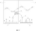
- some embodiments of the present disclosure provide a mobile terminal, including a first module 1 and a second module 2, where the first module 1 and the second module 2 may be in a folded state or an unfolded state.
- the first module 1 is provided with a first antenna radiation branch 4, the first antenna radiation branch 4 is provided with a first feed point 41 and a first ground point 42, and the first feed point 41 is electrically connected to a first feed source 7 via a switch 5.
- the second module 2 is provided with a second antenna radiation branch 3, and the second antenna radiation branch 3 is provided with a second feed point 31 and a second ground point 32.
- the switch 5 In the case where the first module 1 and the second module 2 are in the folded state, the switch 5 is in the off state, and in the case where the first module 1 and the second module 2 are in the unfolded state, the switch 5 is in the on state.
- the mobile terminal may be a mobile phone, a tablet personal computer (Tablet Personal Computer), a laptop computer (Laptop Computer), a personal digital assistant (personal digital assistant, PDA), a mobile Internet device (Mobile Internet Device, MID), a wearable device (Wearable Device), or the like.
- the first module 1 may be a shell, a display module, or a combined structure of a shell and a display module; and the second module 2 may be a shell, a display module, or a combined structure of a shell and a display module.
- the first module 1 and the second module 2 may be connected by a rotating shaft or sliding rail. In the case where the first module 1 and the second module 2 are connected via a rotating shaft, the first module 1 and the second module 2 may get into the folded state or unfolded state by rotating around the rotating shaft. In the case where the first module 1 and the second module 2 are connected by a sliding rail, the first module 1 and the second module 2 may get into the folded state or unfolded state by sliding along the sliding rail. Alternatively, the first module 1 and the second module 2 may get into the folded state or unfolded state in other connection manners, which is not limited in the embodiments of the present disclosure.
- the first antenna radiation branch 4 may adopt a flexible printed circuit (Flexible Printed Circuit, FPC), laser directed structuring (Laser Directed Structuring, LDS), or a breakpoint middle frame.
- the second antenna radiation branch 3 may adopt an FPC, LDS, or a breakpoint middle frame.
- the first feed source 7 may be a 3rd-Generation (3rd-Generation, 3G), 4th-Generation mobile communication technology (4th-Generation mobile communication technology, 4G), 5th-Generation (5th-Generation, 5G), wireless fidelity (Wireless-Fidelity, Wi-Fi), or global positioning system (Global Positioning System, GPS) radio frequency module which requires multiple antennas.
- the second feed point 31 may be electrically connected to the second feed source 6, where the second feed source 6 may be a 3G, 4G, 5G, Wi-Fi, or GPS radio frequency module which requires multiple antennas.
- the second feed point 31 may be electrically connected to the second feed source 6 via a normally-closed switch.
- the switch in the case where the first module and the second module are in the folded state, the switch is in the off state, that is, the first antenna radiation branch is isolated from the feed source, and only the second antenna radiation branch works normally.
- the switch In the case where the first module and the second module are in the unfolded state, the switch is in the on state, that is, both the first antenna radiation branch and the second antenna radiation branch can work normally. Therefore, a data transmission rate of an antenna of a foldable-screen mobile terminal can be flexibly adjusted by changing relative status of the first module and the second module, so that the foldable-screen mobile terminal can better adapt to the communication requirements for different data transmission rates.
- the first antenna radiation branch 4 is in capacitive coupling with the second antenna radiation branch 3.
- the first antenna radiation branch 4 and the second antenna radiation branch 3 may be spaced by a specific distance. Specifically, the distance may be greater than or equal to a preset threshold.
- the first antenna radiation branch is in capacitive coupling with the second antenna radiation branch. Therefore, in the case where the first module and the second module are in the folded state, the antenna energy radiated from the second antenna radiation branch can be transferred to the first antenna radiation branch through capacitive coupling for secondary radiation, thereby increasing the radiation capability and bandwidth of the antenna.
- FIG. 3 is a schematic diagram of comparing antenna resonant modes generated by the mobile terminal in the related art and the mobile terminal in this implementation in the case where the first module and the second module are in the folded state.
- H1 and H2 represent two antenna resonant modes generated by the mobile terminal in the related art in the case where the first module and the second module thereof are in the folded state.
- H1-1 and H2-1 represent two antenna resonant modes generated by the first antenna radiation branch 4 of the mobile terminal in this implementation in the case where the first module 1 and the second module 2 are in the folded state.
- HI-2 and H2-2 represent two antenna resonant modes generated by the second antenna radiation branch 3 of the mobile terminal in this implementation through coupling in the case where the first module 1 and the second module 2 are in the folded state.
- the bandwidth of the antenna resonant mode H1-1 is wider than that of the antenna resonant mode H1
- the bandwidth of the antenna resonant mode H2-1 is wider than that of the antenna resonant mode H2 which indicates that the second antenna radiation branch 3 can enlarge the radiation space of the first antenna radiation branch 4, thereby further improving the radiation capability of the first antenna radiation branch 4.
- the first antenna radiation branch 4 is aligned with the second antenna radiation branch 3.
- the first antenna radiation branch 4 is aligned with the second antenna radiation branch 3, which can be understood as that the shape and dimension of the first antenna radiation branch 4 are consistent with those of the second antenna radiation branch 3.
- the first antenna radiation branch 4 is completely aligned with the second antenna radiation branch 3.
- the first antenna radiation branch is aligned with the second antenna radiation branch. This can improve the coupling effect of the first antenna radiation branch and the second antenna radiation branch, and further improve the radiation capability of the antenna and making the mobile terminal look more symmetrical and neater.
- the first antenna radiation branch 4 is further provided with a tuning point, and the tuning point is electrically connected to a tuning circuit 8.
- the tuning circuit 8 may be grounded and may be used to adjust the resonant frequency of the first antenna radiation branch 4 in the case where the first module 1 and the second module 2 are in the folded state, so that the resonant frequency of the first antenna radiation branch 4 can adapt to that of the second antenna radiation branch 3.
- the first antenna radiation branch 4 may be used to generate two resonant modes: low-frequency resonance and high-frequency resonance.
- the resonant frequency of the first antenna radiation branch can be adjusted as required.
- the first antenna radiation branch can be a parasitic antenna radiation branch of the second antenna radiation branch, thereby increasing the radiation capability and/or the bandwidth of the antenna.
- the tuning circuit 8 is a switching circuit or a high-frequency filtering circuit.
- the switching circuit may be in the on state at a high frequency and in the off state at a low frequency.
- the high-frequency filtering circuit may be equivalent to an open circuit or high-impedance circuit at a low frequency, and equivalent to a short circuit or low-impedance circuit at a high frequency.
- the second feed point 31 is electrically connected to the second feed source 6.
- the mobile terminal further includes a combiner 10 and a combination switch 11, where the combiner 10 is electrically connected to the second feed source 6, and the combiner 10 is electrically connected to the first feed source 7 via the combination switch 11.
- the combination switch 11 is disconnected from the combiner 10.
- the combination switch 11 is connected to the combiner 10.
- the combination switch 11 may be a single-pole single-throw switch or single-pole multi-throw switch. That the combination switch 11 is a single-pole double-throw switch is used as an example.
- one fixed end of the combination switch 11 may be electrically connected to a power amplifier 9, the other fixed end may be electrically connected to the combiner 10, the moving end may be electrically connected to the first feed source, and the combiner is also electrically connected to the power amplifier 9.
- the antenna can be a multiple-input multiple-output (Multiple-Input Multiple-Output, MIMO) antenna in the case where the SAR does not exceed the standard, and can be a non-MIMO antenna in the case where the SAR exceeds the standard.
- MIMO Multiple-Input Multiple-Output
- the first antenna radiation branch and the second antenna radiation branch can disperse antenna hotspots, thereby reducing the SAR without decreasing the antenna performance, and further reducing adverse effects of antenna electromagnetic radiation on users.
- some embodiments of the present disclosure further provide an antenna control method, applied to the mobile terminal in any one of the implementations of the foregoing embodiments, and including the following steps.
- Step 501 Control the switch to be in the off state in the case where the first module and the second module are in the folded state; and control the switch to be in the on state in the case where the first module and the second module are in the unfolded state.
- the switch in the case where the first module and the second module are in the folded state, the switch is in the off state, that is, the first antenna radiation branch is isolated from the feed source, and only the second antenna radiation branch works normally; and in the case where the first module and the second module are in the unfolded state, the switch is in the on state, that is, the first antenna radiation branch and the second antenna radiation branch each works independently and normally. Therefore, a data transmission rate of an antenna of a foldable-screen mobile terminal can be flexibly adjusted by changing relative status of the first module and the second module, so that the foldable-screen mobile terminal can better adapt to the communication requirements for different data transmission rates.
- the antenna control method in the embodiments is applied to the mobile terminal in some of the implementations of the embodiments and includes the following steps.
- the antenna can be a MIMO antenna in the case where the SAR does not exceed the standard, and can be a non-MIMO antenna in the case where the SAR exceeds the standard. Therefore, the first antenna radiation branch and the second antenna radiation branch can disperse antenna hotspots, thereby reducing the SAR without decreasing the antenna performance, and further reducing adverse effects on users.
- FIG. 6 is a schematic diagram of a hardware structure of a mobile terminal implementing embodiments of the present disclosure.
- the mobile terminal 600 includes, but is not limited to, a radio frequency unit 601, a network module 602, an audio output unit 603, an input unit 604, a sensor 605, a display unit 606, a user input unit 607, an interface unit 608, a memory 609, a processor 610, a power supply 611, and other components.
- a radio frequency unit 601 includes, but is not limited to, a radio frequency unit 601, a network module 602, an audio output unit 603, an input unit 604, a sensor 605, a display unit 606, a user input unit 607, an interface unit 608, a memory 609, a processor 610, a power supply 611, and other components.
- the structure of the mobile terminal shown in FIG. 6 constitutes no limitation on the mobile terminal, and the mobile terminal may include more or fewer parts than those shown in the figure, or combine some parts, or have a different part arrangement.
- the processor 610 is configured to:
- processor 610 is further configured to:
- the mobile terminal 600 can implement each process implemented by the mobile terminal in the foregoing embodiments. To avoid repetition, details are not described herein again.
- the switch in the case where the first module and the second module are in the folded state, the switch is in the off state, that is, the antenna radiation branch that is electrically connected to the switch is isolated from the feed source, and only one antenna radiation branch works normally.
- the switch In the case where the first module and the second module are in the unfolded state, the switch is in the on state, that is, the first antenna radiation branch and the second antenna radiation branch each works independently and normally. Therefore, a data transmission rate of an antenna of a foldable-screen mobile terminal can be flexibly adjusted by changing relative status of the first module and the second module, so that the foldable-screen mobile terminal can better adapt to the communication requirements for different data transmission rates.
- the radio frequency unit 601 may be configured to receive and send information or a signal in a call process. Specifically, after receiving downlink data from a base station, the radio frequency unit 601 sends the downlink data to the processor 610 for processing. In addition, the radio frequency unit 601 sends uplink data to the base station.
- the radio frequency unit 601 includes but is not limited to an antenna, at least one amplifier, a transceiver, a coupler, a low noise amplifier, a duplexer, and the like.
- the radio frequency unit 601 can also communicate with another device through a wireless communications system and network.
- the mobile terminal provides wireless broadband Internet access for a user by using the network module 602, for example, helping the user send and receive an email, browse a web page, and access streaming media.
- the audio output unit 603 can convert audio data received by the radio frequency unit 601 or the network module 602 or stored in the memory 609 into an audio signal, and output the audio signal into sound. Moreover, the audio output unit 603 may further provide audio output (for example, call signal receiving sound and message receiving sound) related to a specific function executed by the mobile terminal 600.
- the audio output unit 603 includes a loudspeaker, a buzzer, a receiver, and the like.
- the input unit 604 is configured to receive audio or radio frequency signals.
- the input unit 604 may include a graphics processing unit (Graphics Processing Unit, GPU) 6041 and a microphone 6042.
- the graphics processing unit 6041 is configured to process image data of a static picture or a video obtained by an image capture apparatus (for example, a camera) in video capture mode or image capture mode.
- a processed image frame can be displayed on the display unit 606.
- An image frame processed by the graphics processing unit 6041 may be stored in the memory 609 (or another storage medium) or sent by the radio frequency unit 601 or the network module 602.
- the microphone 6042 may receive sound and can process such sound into audio data.
- the processed audio data may be converted, in a call mode, into a format that can be sent by using the radio frequency unit 601 to a mobile communication base station, for outputting.
- the mobile terminal 600 further includes at least one sensor 605 such as an optical sensor, a motion sensor, or another sensor.
- the optical sensor includes an ambient light sensor and a proximity sensor.
- the ambient light sensor may adjust luminance of the display panel 6061 according to brightness of ambient light.
- the proximity sensor may turn off the display panel 6061 and/or backlight when the mobile terminal 600 is moved to an ear.
- an accelerometer sensor may detect magnitude of an acceleration in each direction (generally three axes), and may detect magnitude and a direction of gravity when being static.
- the accelerometer sensor may be used for recognizing a mobile terminal gesture (for example, horizontal and vertical screen switching, a related game, or magnetometer posture calibration), a function related to vibration recognition (for example, a pedometer or a strike), or the like.
- the sensor 605 may further include a fingerprint sensor, a pressure sensor, an iris sensor, a molecular sensor, a gyroscope, a barometer, a hygrometer, a thermometer, an infrared sensor, and the like. This is not described herein.
- the display unit 606 is configured to display information entered by a user or information provided for the user.
- the display unit 606 may include the display panel 6061, and the display panel 6061 may be configured in a form of a liquid crystal display (Liquid Crystal Display, LCD), an organic light-emitting diode (Organic Light-Emitting Diode, OLED), or the like.
- LCD Liquid Crystal Display
- OLED Organic Light-Emitting Diode
- the user input unit 607 may be configured to receive inputted digit or character information and generate key signal input related to user setting and function control of the mobile terminal.
- the user input unit 607 includes a touch panel 6071 and other input devices 6072.
- the touch panel 6071 also called a touch screen, can collect a touch operation of the user on or near the touch panel 6071 (For example, the user uses any suitable object or accessory such as a finger or a stylus to operate on or near the touch panel 6071).
- the touch panel 6071 may include two parts: a touch detection apparatus and a touch controller.
- the touch detection apparatus detects a touch position of the user, detects a signal brought by the touch operation, and transmits the signal to the touch controller.
- the touch controller receives touch information from the touch detection apparatus, converts the touch information into contact coordinates, sends the contact coordinates to the processor 610, and receives and executes a command sent by the processor 610.
- the touch panel 6071 may be implemented by using a plurality of types such as a resistive type, a capacitive type, an infrared ray, and a surface acoustic wave.
- the user input unit 607 may further include the other input devices 6072.
- the another input device 6072 may include, but not limited to, a physical keyboard, a function key (for example, a volume control key or a switch key), a trackball, a mouse, and a joystick. Details are not described herein.
- the touch panel 6071 may cover the display panel 6061.
- the touch panel 6071 transmits the touch operation to the processor 610 to determine a type of a touch event. Then, the processor 610 provides corresponding visual output on the display panel 6061 based on the type of the touch event.
- the touch panel 6071 and the display panel 6061 are used as two independent parts to implement input and output functions of the mobile terminal, in some embodiments, the touch panel 6071 and the display panel 6061 may be integrated to implement the input and output functions of the mobile terminal. Details are not described herein.
- the interface unit 608 is an interface connecting an external apparatus to the mobile terminal 600.
- the external apparatus may include a wired or wireless headset jack, an external power supply (or a battery charger) port, a wired or wireless data port, a storage card port, a port for connecting an apparatus having an identification module, an audio input/output (Input/Output, I/O) port, a video I/O port, a headset jack, or the like.
- the interface unit 608 may be configured to receive input (such as data information and power) from the external apparatus and transmit the received input to one or more elements in the mobile terminal 600, or may be configured to transmit data between the mobile terminal 600 and the external apparatus.
- the memory 609 may be configured to store software programs and various data.
- the memory 609 may mainly include a program storage area and a data storage area.
- the program storage area may store an operating system, an application program required by at least one function (such as a sound playback function and an image playback function), and the like.
- the data storage area may store data (such as audio data and a phone book) created based on the use of the mobile phone, and the like.
- the memory 609 may include a high-speed random access memory or a nonvolatile memory, for example, at least one disk storage device, a flash memory, or another volatile solid-state storage device.
- the processor 610 is a control center of the mobile terminal, and is connected to all parts of the entire mobile terminal by using various interfaces and lines, and performs various functions of the mobile terminal and processes data by running or executing the software program and/or the module that are/is stored in the memory 609 and invoking the data stored in the memory 609, to implement overall monitoring on the mobile terminal.
- the processor 610 may include one or more processing units.
- the processor 610 may integrate an application processor and a modem processor.
- the application processor mainly processes an operating system, a user interface, an application program, and the like.
- the modem processor mainly processes wireless communication. It may be understood that the foregoing modem processor may not be integrated into the processor 610.
- the mobile terminal 600 may further include a power supply 611 (such as a battery) that supplies power to each component.
- a power supply 611 such as a battery
- the power supply 611 may be logically connected to the processor 610 by using a power supply management system, to implement functions such as charging, discharging, and power consumption management by using the power supply management system.
- the mobile terminal 600 includes some function modules not shown, and details are not described herein.
- an embodiment of the present disclosure further provides a mobile terminal, including a processor 610, a memory 609, and a computer program that is stored in the memory 609 and executable on the processor 610.
- the processor 610 implements the foregoing processes of the antenna control method embodiment and a same technical effect can be achieved. To avoid repetition, details are not described herein again.
- An embodiment of the present disclosure further provides a computer readable storage medium.
- the computer readable storage medium stores a computer program, the computer program, when executed by a processor, implements the processes of the foregoing embodiments of the antenna control method, and same technical effects can be achieved. To avoid repetition, details are not described herein again.
- the computer-readable storage medium includes a read-only memory (Read-Only Memory, ROM), a random access memory (Random Access Memory, RAM), a magnetic disk, an optical disc, or the like.
- the terms "include”, “comprise”, or any of their variants are intended to cover a non-exclusive inclusion, such that a process, a method, an article, or an apparatus that includes a list of elements not only includes those elements, but also includes other elements that are not expressly listed, or further includes elements inherent to such a process, method, article, or apparatus.
- An element limited by “includes a " does not, without more constraints, preclude the presence of additional identical elements in the process, method, article, or apparatus that includes the element.
- the computer software product is stored in a storage medium (such as a ROM/RAM, a magnetic disk, or an optical disc) and includes several instructions for instructing user equipment (which may be a mobile phone, a computer, a server, an air conditioner, or a network device) to execute the methods described in the embodiments of the present disclosure.
- a storage medium such as a ROM/RAM, a magnetic disk, or an optical disc
- user equipment which may be a mobile phone, a computer, a server, an air conditioner, or a network device
- the disclosed apparatuses and methods may be implemented in other ways.
- the apparatus embodiments described above are only an example.
- the division of the units is only logical function division. There may be other division manners in actual implementation, for example, multiple units or components may be combined or integrated into another system, or some features may be ignored or not implemented.
- the mutual coupling, direct coupling, or communication connection shown or discussed may be indirect coupling or communication connection through some interfaces, apparatuses, or units, and may be in electrical, mechanical, or other forms.
- the units described as separate components may be or may not be physically separated, and the components displayed as units may be or may not be physical units, that is, may be located in one place or distributed on multiple network units. Some or all of the units may be selected according to actual needs to achieve the objective of the solutions of the embodiments.
- the function may be stored in a computer-readable storage medium.
- the computer software product is stored in a storage medium, and includes several instructions for instructing a computer device (which may be a personal computer, a server, a network device, or the like) to perform all or some of the steps of the methods described in the embodiments of the present disclosure.
- the storage medium includes various mediums, such as a USB flash disk, a removable hard disk, a ROM, a RAM, a magnetic disk, or an optical disc, that can store program code.
- the program may be stored in a computer-readable storage medium.
- the foregoing storage medium may be a magnetic disk, an optical disc, a read-only memory (Read-Only Memory, ROM), a random access memory (Random Access Memory, RAM), or the like.
- a processing unit can be implemented in one or more application-specific integrated circuits (Application Specific Integrated Circuits, ASIC), a digital signal processor (Digital Signal Processor, DSP), a digital signal processing device (DSP Device, DSPD), a programmable logic device (Programmable Logic Device, PLD), a field-programmable gate array (Field-Programmable Gate Array, FPGA), a general-purpose processor, a controller, a microcontroller, a microprocessor, other electronic units used to perform the functions described in this disclosure, or a combination thereof.
- ASIC Application Specific Integrated Circuits
- DSP Digital Signal Processor
- DSP Device digital signal processing device
- PLD programmable logic device
- FPGA Field-Programmable Gate Array
- a general-purpose processor a controller, a microcontroller, a microprocessor, other electronic units used to perform the functions described in this disclosure, or a combination thereof.
- the technology in the embodiments of the present disclosure may be implemented through modules (for example, procedures or functions) that perform the functions in the embodiments of the present disclosure.
- Software codes can be stored in the memory and executed by the processor.
- the memory may be implemented inside or outside the processor.
Landscapes
- Engineering & Computer Science (AREA)
- Computer Hardware Design (AREA)
- Theoretical Computer Science (AREA)
- Human Computer Interaction (AREA)
- Signal Processing (AREA)
- Physics & Mathematics (AREA)
- General Engineering & Computer Science (AREA)
- General Physics & Mathematics (AREA)
- Computer Networks & Wireless Communication (AREA)
- Mathematical Physics (AREA)
- Telephone Function (AREA)
- Telephone Set Structure (AREA)
Abstract
Description
- This application claims priority to
Chinese Patent Application No. 201811595496.6 filed in china on December 25, 2018 - The present disclosure relates to the field of communications technologies, and in particular, to a mobile terminal and an antenna control method.
- In recent years, foldable-screen mobile terminals (for example, foldable-screen phones) have gradually entered people's vision. It is well known that, to realize the communication function of a mobile terminal, an antenna needs to be installed on it, and the antenna is mainly used for data transmission. Different communication requirements require an antenna to have different data transmission rates. Generally, calls or web browsing have lower requirements for data transmission rates, while some games or videos have higher requirements.
- Antennas of foldable-screen mobile terminals in the related art often have fixed data transmission rates. As a result, such mobile terminals have lower adaptability to communication requirements for different data transmission rates.
- Embodiments of the present disclosure provide a mobile terminal and an antenna control method, to resolve a problem that antennas of foldable-screen mobile terminals in the related art often have fixed data transmission rates and therefore such mobile terminals have lower adaptability to communication requirements for different data transmission rates.
- To resolve the foregoing technical problem, the present disclosure is implemented as follows:
- According to a first aspect, an embodiment of the present disclosure provides a mobile terminal, including a first module and a second module, where the first module and the second module may be in a folded state or an unfolded state.
- The first module is provided with a first antenna radiation branch, where the first antenna radiation branch is provided with a first feed point and a first ground point, and the first feed point is electrically connected to a first feed source via a switch; and the second module is provided with a second antenna radiation branch, where the second antenna radiation branch is provided with a second feed point and a second ground point.
- In a case where the first module and the second module are in the folded state, the switch is in the off state, and in a case where the first module and the second module are in the unfolded state, the switch is in the on state.
- According to a second aspect, an embodiment of the present disclosure further provides an antenna control method, applied to the foregoing mobile terminal, and including:
- controlling the switch to be in the off state in the case where the first module and the second module are in the folded state; and
- controlling the switch to be in the on state in the case where the first module and the second module are in the unfolded state.
- According to a third aspect, an embodiment of the present disclosure further provides a mobile terminal, including a processor, a memory, and a computer program that is stored in the memory and executable on the processor, where when the processor executes the computer program, the steps of the foregoing antenna control method are implemented.
- According to a fourth aspect, an embodiment of the present disclosure further provides a computer-readable storage medium, where the computer-readable storage medium stores a computer program, and when the computer program is executed by a processor, the steps of the foregoing antenna control method are implemented.
- The present disclosure has the following beneficial effects:
- In the embodiments of the present disclosure, in the case where the first module and the second module are in the folded state, the switch is in the off state, that is, the first antenna radiation branch is isolated from the feed source, and only the second antenna radiation branch works normally; and in the case where the first module and the second module are in the unfolded state, the switch is in the on state, that is, the first antenna radiation branch and the second antenna radiation branch each works independently and normally. Therefore, a data transmission rate of an antenna of a foldable-screen mobile terminal can be flexibly adjusted by changing relative status of the first module and the second module, so that the foldable-screen mobile terminal can better adapt to the communication requirements for different data transmission rates.
- To describe the technical solutions in embodiments of the present disclosure more clearly, the following briefly describes the accompanying drawings required for describing the embodiments of the present disclosure. Apparently, the accompanying drawings in the following description show merely some embodiments of the present disclosure, and a person of ordinary skill in the art may still derive another drawing from these accompanying drawings without creative efforts.
-
FIG. 1 is a structural diagram of a mobile terminal with a first module and a second module being in an unfolded state according to some embodiments of the present disclosure; -
FIG. 2 is a structural diagram of the mobile terminal, shown inFIG. 1 , with the first module and the second module being in a folded state; -
FIG. 3 is an exemplary diagram of the mobile terminal according to some embodiments of the present disclosure; -
FIG. 4 is another structural diagram of the mobile terminal with the first module and the second module being in the unfolded state according to some embodiments of the present disclosure; -
FIG. 5 is a flowchart of an antenna control method according to some embodiments of the present disclosure; and -
FIG. 6 is a structural diagram of the mobile terminal according to some embodiments of the present disclosure. - The following clearly and completely describes the technical solutions in the embodiments of the present disclosure with reference to the accompanying drawings in the embodiments of the present disclosure. Apparently, the described embodiments are some rather than all of the embodiments of the present disclosure. All other embodiments obtained by a person of ordinary skill in the art based on the embodiments of the present disclosure without creative efforts shall fall within the protection scope of the present disclosure.
- As shown in
FIG. 1 andFIG. 2 , some embodiments of the present disclosure provide a mobile terminal, including afirst module 1 and asecond module 2, where thefirst module 1 and thesecond module 2 may be in a folded state or an unfolded state. - The
first module 1 is provided with a firstantenna radiation branch 4, the firstantenna radiation branch 4 is provided with afirst feed point 41 and afirst ground point 42, and thefirst feed point 41 is electrically connected to afirst feed source 7 via aswitch 5. Thesecond module 2 is provided with a secondantenna radiation branch 3, and the secondantenna radiation branch 3 is provided with asecond feed point 31 and asecond ground point 32. - In the case where the
first module 1 and thesecond module 2 are in the folded state, theswitch 5 is in the off state, and in the case where thefirst module 1 and thesecond module 2 are in the unfolded state, theswitch 5 is in the on state. - The mobile terminal may be a mobile phone, a tablet personal computer (Tablet Personal Computer), a laptop computer (Laptop Computer), a personal digital assistant (personal digital assistant, PDA), a mobile Internet device (Mobile Internet Device, MID), a wearable device (Wearable Device), or the like.
- The
first module 1 may be a shell, a display module, or a combined structure of a shell and a display module; and thesecond module 2 may be a shell, a display module, or a combined structure of a shell and a display module. Thefirst module 1 and thesecond module 2 may be connected by a rotating shaft or sliding rail. In the case where thefirst module 1 and thesecond module 2 are connected via a rotating shaft, thefirst module 1 and thesecond module 2 may get into the folded state or unfolded state by rotating around the rotating shaft. In the case where thefirst module 1 and thesecond module 2 are connected by a sliding rail, thefirst module 1 and thesecond module 2 may get into the folded state or unfolded state by sliding along the sliding rail. Alternatively, thefirst module 1 and thesecond module 2 may get into the folded state or unfolded state in other connection manners, which is not limited in the embodiments of the present disclosure. - The first
antenna radiation branch 4 may adopt a flexible printed circuit (Flexible Printed Circuit, FPC), laser directed structuring (Laser Directed Structuring, LDS), or a breakpoint middle frame. The secondantenna radiation branch 3 may adopt an FPC, LDS, or a breakpoint middle frame. Thefirst feed source 7 may be a 3rd-Generation (3rd-Generation, 3G), 4th-Generation mobile communication technology (4th-Generation mobile communication technology, 4G), 5th-Generation (5th-Generation, 5G), wireless fidelity (Wireless-Fidelity, Wi-Fi), or global positioning system (Global Positioning System, GPS) radio frequency module which requires multiple antennas. - As shown in
FIG. 1 ,FIG. 2 , andFIG. 4 , thesecond feed point 31 may be electrically connected to thesecond feed source 6, where thesecond feed source 6 may be a 3G, 4G, 5G, Wi-Fi, or GPS radio frequency module which requires multiple antennas. In addition, it should be noted that thesecond feed point 31 may be electrically connected to thesecond feed source 6 via a normally-closed switch. - In the embodiments of the present disclosure, in the case where the first module and the second module are in the folded state, the switch is in the off state, that is, the first antenna radiation branch is isolated from the feed source, and only the second antenna radiation branch works normally. In the case where the first module and the second module are in the unfolded state, the switch is in the on state, that is, both the first antenna radiation branch and the second antenna radiation branch can work normally. Therefore, a data transmission rate of an antenna of a foldable-screen mobile terminal can be flexibly adjusted by changing relative status of the first module and the second module, so that the foldable-screen mobile terminal can better adapt to the communication requirements for different data transmission rates.
- Optionally, in the case where the
first module 1 and thesecond module 2 are in the folded state, the firstantenna radiation branch 4 is in capacitive coupling with the secondantenna radiation branch 3. - The first
antenna radiation branch 4 and the secondantenna radiation branch 3 may be spaced by a specific distance. Specifically, the distance may be greater than or equal to a preset threshold. - In the case where the first module and the second module are in the folded state, the first antenna radiation branch is in capacitive coupling with the second antenna radiation branch. Therefore, in the case where the first module and the second module are in the folded state, the antenna energy radiated from the second antenna radiation branch can be transferred to the first antenna radiation branch through capacitive coupling for secondary radiation, thereby increasing the radiation capability and bandwidth of the antenna.
- Specifically, for a more intuitive understanding of the beneficial effects of this implementation, see
FIG. 3. FIG. 3 is a schematic diagram of comparing antenna resonant modes generated by the mobile terminal in the related art and the mobile terminal in this implementation in the case where the first module and the second module are in the folded state. H1 and H2 represent two antenna resonant modes generated by the mobile terminal in the related art in the case where the first module and the second module thereof are in the folded state. H1-1 and H2-1 represent two antenna resonant modes generated by the firstantenna radiation branch 4 of the mobile terminal in this implementation in the case where thefirst module 1 and thesecond module 2 are in the folded state. HI-2 and H2-2 represent two antenna resonant modes generated by the secondantenna radiation branch 3 of the mobile terminal in this implementation through coupling in the case where thefirst module 1 and thesecond module 2 are in the folded state. - It is easy to learn from
FIG.3 that the mobile terminal in this implementation generates the two antenna resonant modes H1-1 and H2-1 corresponding to the antenna resonant modes H1 and H2 respectively by the firstantenna radiation branch 4, and further generates the two antenna resonant modes HI-2 and H2-2 by the secondantenna radiation branch 3 through coupling. Apparently, the total bandwidth of the antenna resonant modes Hl-1, H2-1, HI-2, and H2-2 is greater than that of the antenna resonant modes H1 and H2, which indicates that the mobile terminal in this implementation has a wider antenna bandwidth and a higher radiation capability than the mobile terminal in the related art. In addition, as shown inFIG. 3 , the bandwidth of the antenna resonant mode H1-1 is wider than that of the antenna resonant mode H1, and the bandwidth of the antenna resonant mode H2-1 is wider than that of the antenna resonant mode H2, which indicates that the secondantenna radiation branch 3 can enlarge the radiation space of the firstantenna radiation branch 4, thereby further improving the radiation capability of the firstantenna radiation branch 4. - Optionally, in the case where the
first module 1 and thesecond module 2 are in the folded state, the firstantenna radiation branch 4 is aligned with the secondantenna radiation branch 3. - In the case where the
first module 1 and thesecond module 2 are in the folded state, the firstantenna radiation branch 4 is aligned with the secondantenna radiation branch 3, which can be understood as that the shape and dimension of the firstantenna radiation branch 4 are consistent with those of the secondantenna radiation branch 3. In addition, in the case where thefirst module 1 and thesecond module 2 are in the folded state, the firstantenna radiation branch 4 is completely aligned with the secondantenna radiation branch 3. - In the case where the first module and the second module are in the folded state, the first antenna radiation branch is aligned with the second antenna radiation branch. This can improve the coupling effect of the first antenna radiation branch and the second antenna radiation branch, and further improve the radiation capability of the antenna and making the mobile terminal look more symmetrical and neater.
- Optionally, the first
antenna radiation branch 4 is further provided with a tuning point, and the tuning point is electrically connected to atuning circuit 8. - The
tuning circuit 8 may be grounded and may be used to adjust the resonant frequency of the firstantenna radiation branch 4 in the case where thefirst module 1 and thesecond module 2 are in the folded state, so that the resonant frequency of the firstantenna radiation branch 4 can adapt to that of the secondantenna radiation branch 3. Specifically, the firstantenna radiation branch 4 may be used to generate two resonant modes: low-frequency resonance and high-frequency resonance. - As the tuning circuit is provided, the resonant frequency of the first antenna radiation branch can be adjusted as required. In this way, in the case where the first module and the second module are in the folded state, the first antenna radiation branch can be a parasitic antenna radiation branch of the second antenna radiation branch, thereby increasing the radiation capability and/or the bandwidth of the antenna.
- Optionally, the
tuning circuit 8 is a switching circuit or a high-frequency filtering circuit. - The switching circuit may be in the on state at a high frequency and in the off state at a low frequency. The high-frequency filtering circuit may be equivalent to an open circuit or high-impedance circuit at a low frequency, and equivalent to a short circuit or low-impedance circuit at a high frequency.
- Optionally, the
second feed point 31 is electrically connected to thesecond feed source 6. The mobile terminal further includes acombiner 10 and acombination switch 11, where thecombiner 10 is electrically connected to thesecond feed source 6, and thecombiner 10 is electrically connected to thefirst feed source 7 via thecombination switch 11. - In the case where the
first module 1 and thesecond module 2 are in the unfolded state, and the specific absorption rate (Specific Absorption Rate, SAR) of the mobile terminal is less than or equal to a preset threshold, thecombination switch 11 is disconnected from thecombiner 10. - In the case where the
first module 1 and thesecond module 2 are in the unfolded state, and the SAR of the mobile terminal is greater than the preset threshold, thecombination switch 11 is connected to thecombiner 10. - The combination switch 11 may be a single-pole single-throw switch or single-pole multi-throw switch. That the
combination switch 11 is a single-pole double-throw switch is used as an example. In the case where thecombination switch 11 is a single-pole double-throw switch, one fixed end of thecombination switch 11 may be electrically connected to apower amplifier 9, the other fixed end may be electrically connected to thecombiner 10, the moving end may be electrically connected to the first feed source, and the combiner is also electrically connected to thepower amplifier 9. - As the combiner and combination switch are provided, the antenna can be a multiple-input multiple-output (Multiple-Input Multiple-Output, MIMO) antenna in the case where the SAR does not exceed the standard, and can be a non-MIMO antenna in the case where the SAR exceeds the standard. In this way, the first antenna radiation branch and the second antenna radiation branch can disperse antenna hotspots, thereby reducing the SAR without decreasing the antenna performance, and further reducing adverse effects of antenna electromagnetic radiation on users.
- As shown in
FIG. 5 , some embodiments of the present disclosure further provide an antenna control method, applied to the mobile terminal in any one of the implementations of the foregoing embodiments, and including the following steps. - Step 501: Control the switch to be in the off state in the case where the first module and the second module are in the folded state; and control the switch to be in the on state in the case where the first module and the second module are in the unfolded state.
- In the embodiments of the present disclosure, in the case where the first module and the second module are in the folded state, the switch is in the off state, that is, the first antenna radiation branch is isolated from the feed source, and only the second antenna radiation branch works normally; and in the case where the first module and the second module are in the unfolded state, the switch is in the on state, that is, the first antenna radiation branch and the second antenna radiation branch each works independently and normally. Therefore, a data transmission rate of an antenna of a foldable-screen mobile terminal can be flexibly adjusted by changing relative status of the first module and the second module, so that the foldable-screen mobile terminal can better adapt to the communication requirements for different data transmission rates.
- Optionally, the antenna control method in the embodiments is applied to the mobile terminal in some of the implementations of the embodiments and includes the following steps.
- Control the combination switch to be disconnected from the combiner in the case where the first module and the second module are in the unfolded state, and the SAR of the mobile terminal is less than or equal to a preset threshold.
- Control the combination switch to be connected to the combiner in the case where the first module and the second module are in the unfolded state, and the SAR of the mobile terminal is greater than the preset threshold.
- In this way, the antenna can be a MIMO antenna in the case where the SAR does not exceed the standard, and can be a non-MIMO antenna in the case where the SAR exceeds the standard. Therefore, the first antenna radiation branch and the second antenna radiation branch can disperse antenna hotspots, thereby reducing the SAR without decreasing the antenna performance, and further reducing adverse effects on users.
-
FIG. 6 is a schematic diagram of a hardware structure of a mobile terminal implementing embodiments of the present disclosure. Themobile terminal 600 includes, but is not limited to, aradio frequency unit 601, anetwork module 602, anaudio output unit 603, aninput unit 604, asensor 605, adisplay unit 606, auser input unit 607, aninterface unit 608, amemory 609, aprocessor 610, apower supply 611, and other components. A person skilled in the art may understand that the structure of the mobile terminal shown inFIG. 6 constitutes no limitation on the mobile terminal, and the mobile terminal may include more or fewer parts than those shown in the figure, or combine some parts, or have a different part arrangement. In this embodiment of the present disclosure, the mobile terminal includes, but is not limited to, a mobile phone, a tablet computer, a laptop computer, a palmtop computer, an in-vehicle terminal, a wearable device, a pedometer, and the like. - The
processor 610 is configured to: - control the switch to be in the off state in the case where the first module and the second module are in the folded state; and
- control the switch to be in the on state in the case where the first module and the second module are in the unfolded state.
- Optionally, the
processor 610 is further configured to: - control the combination switch to be disconnected from the combiner in the case where the first module and the second module are in the unfolded state, and the SAR of the mobile terminal is less than or equal to a preset threshold; and
- control the combination switch to be connected to the combiner in the case where the first module and the second module are in the unfolded state, and the SAR of the mobile terminal is greater than the preset threshold.
- The
mobile terminal 600 can implement each process implemented by the mobile terminal in the foregoing embodiments. To avoid repetition, details are not described herein again. - According to the
mobile terminal 600 in this embodiment of the present disclosure, in the case where the first module and the second module are in the folded state, the switch is in the off state, that is, the antenna radiation branch that is electrically connected to the switch is isolated from the feed source, and only one antenna radiation branch works normally. In the case where the first module and the second module are in the unfolded state, the switch is in the on state, that is, the first antenna radiation branch and the second antenna radiation branch each works independently and normally. Therefore, a data transmission rate of an antenna of a foldable-screen mobile terminal can be flexibly adjusted by changing relative status of the first module and the second module, so that the foldable-screen mobile terminal can better adapt to the communication requirements for different data transmission rates. - It should be understood that, in this embodiment of the present disclosure, the
radio frequency unit 601 may be configured to receive and send information or a signal in a call process. Specifically, after receiving downlink data from a base station, theradio frequency unit 601 sends the downlink data to theprocessor 610 for processing. In addition, theradio frequency unit 601 sends uplink data to the base station. Usually, theradio frequency unit 601 includes but is not limited to an antenna, at least one amplifier, a transceiver, a coupler, a low noise amplifier, a duplexer, and the like. In addition, theradio frequency unit 601 can also communicate with another device through a wireless communications system and network. - The mobile terminal provides wireless broadband Internet access for a user by using the
network module 602, for example, helping the user send and receive an email, browse a web page, and access streaming media. - The
audio output unit 603 can convert audio data received by theradio frequency unit 601 or thenetwork module 602 or stored in thememory 609 into an audio signal, and output the audio signal into sound. Moreover, theaudio output unit 603 may further provide audio output (for example, call signal receiving sound and message receiving sound) related to a specific function executed by themobile terminal 600. Theaudio output unit 603 includes a loudspeaker, a buzzer, a receiver, and the like. - The
input unit 604 is configured to receive audio or radio frequency signals. Theinput unit 604 may include a graphics processing unit (Graphics Processing Unit, GPU) 6041 and amicrophone 6042. Thegraphics processing unit 6041 is configured to process image data of a static picture or a video obtained by an image capture apparatus (for example, a camera) in video capture mode or image capture mode. A processed image frame can be displayed on thedisplay unit 606. An image frame processed by thegraphics processing unit 6041 may be stored in the memory 609 (or another storage medium) or sent by theradio frequency unit 601 or thenetwork module 602. Themicrophone 6042 may receive sound and can process such sound into audio data. The processed audio data may be converted, in a call mode, into a format that can be sent by using theradio frequency unit 601 to a mobile communication base station, for outputting. - The
mobile terminal 600 further includes at least onesensor 605 such as an optical sensor, a motion sensor, or another sensor. Specifically, the optical sensor includes an ambient light sensor and a proximity sensor. The ambient light sensor may adjust luminance of thedisplay panel 6061 according to brightness of ambient light. The proximity sensor may turn off thedisplay panel 6061 and/or backlight when themobile terminal 600 is moved to an ear. As a type of the motion sensor, an accelerometer sensor may detect magnitude of an acceleration in each direction (generally three axes), and may detect magnitude and a direction of gravity when being static. The accelerometer sensor may be used for recognizing a mobile terminal gesture (for example, horizontal and vertical screen switching, a related game, or magnetometer posture calibration), a function related to vibration recognition (for example, a pedometer or a strike), or the like. Thesensor 605 may further include a fingerprint sensor, a pressure sensor, an iris sensor, a molecular sensor, a gyroscope, a barometer, a hygrometer, a thermometer, an infrared sensor, and the like. This is not described herein. - The
display unit 606 is configured to display information entered by a user or information provided for the user. Thedisplay unit 606 may include thedisplay panel 6061, and thedisplay panel 6061 may be configured in a form of a liquid crystal display (Liquid Crystal Display, LCD), an organic light-emitting diode (Organic Light-Emitting Diode, OLED), or the like. - The
user input unit 607 may be configured to receive inputted digit or character information and generate key signal input related to user setting and function control of the mobile terminal. Specifically, theuser input unit 607 includes atouch panel 6071 andother input devices 6072. Thetouch panel 6071, also called a touch screen, can collect a touch operation of the user on or near the touch panel 6071 (For example, the user uses any suitable object or accessory such as a finger or a stylus to operate on or near the touch panel 6071). Thetouch panel 6071 may include two parts: a touch detection apparatus and a touch controller. The touch detection apparatus detects a touch position of the user, detects a signal brought by the touch operation, and transmits the signal to the touch controller. The touch controller receives touch information from the touch detection apparatus, converts the touch information into contact coordinates, sends the contact coordinates to theprocessor 610, and receives and executes a command sent by theprocessor 610. In addition, thetouch panel 6071 may be implemented by using a plurality of types such as a resistive type, a capacitive type, an infrared ray, and a surface acoustic wave. In addition to thetouch panel 6071, theuser input unit 607 may further include theother input devices 6072. Specifically, the anotherinput device 6072 may include, but not limited to, a physical keyboard, a function key (for example, a volume control key or a switch key), a trackball, a mouse, and a joystick. Details are not described herein. - Further, the
touch panel 6071 may cover thedisplay panel 6061. When detecting a touch operation on or near thetouch panel 6071, thetouch panel 6071 transmits the touch operation to theprocessor 610 to determine a type of a touch event. Then, theprocessor 610 provides corresponding visual output on thedisplay panel 6061 based on the type of the touch event. InFIG. 6 , although thetouch panel 6071 and thedisplay panel 6061 are used as two independent parts to implement input and output functions of the mobile terminal, in some embodiments, thetouch panel 6071 and thedisplay panel 6061 may be integrated to implement the input and output functions of the mobile terminal. Details are not described herein. - The
interface unit 608 is an interface connecting an external apparatus to themobile terminal 600. For example, the external apparatus may include a wired or wireless headset jack, an external power supply (or a battery charger) port, a wired or wireless data port, a storage card port, a port for connecting an apparatus having an identification module, an audio input/output (Input/Output, I/O) port, a video I/O port, a headset jack, or the like. Theinterface unit 608 may be configured to receive input (such as data information and power) from the external apparatus and transmit the received input to one or more elements in themobile terminal 600, or may be configured to transmit data between themobile terminal 600 and the external apparatus. - The
memory 609 may be configured to store software programs and various data. Thememory 609 may mainly include a program storage area and a data storage area. The program storage area may store an operating system, an application program required by at least one function (such as a sound playback function and an image playback function), and the like. The data storage area may store data (such as audio data and a phone book) created based on the use of the mobile phone, and the like. In addition, thememory 609 may include a high-speed random access memory or a nonvolatile memory, for example, at least one disk storage device, a flash memory, or another volatile solid-state storage device. - The
processor 610 is a control center of the mobile terminal, and is connected to all parts of the entire mobile terminal by using various interfaces and lines, and performs various functions of the mobile terminal and processes data by running or executing the software program and/or the module that are/is stored in thememory 609 and invoking the data stored in thememory 609, to implement overall monitoring on the mobile terminal. Theprocessor 610 may include one or more processing units. Optionally, theprocessor 610 may integrate an application processor and a modem processor. The application processor mainly processes an operating system, a user interface, an application program, and the like. The modem processor mainly processes wireless communication. It may be understood that the foregoing modem processor may not be integrated into theprocessor 610. - The
mobile terminal 600 may further include a power supply 611 (such as a battery) that supplies power to each component. Optionally, thepower supply 611 may be logically connected to theprocessor 610 by using a power supply management system, to implement functions such as charging, discharging, and power consumption management by using the power supply management system. - In addition, the
mobile terminal 600 includes some function modules not shown, and details are not described herein. - Optionally, an embodiment of the present disclosure further provides a mobile terminal, including a
processor 610, amemory 609, and a computer program that is stored in thememory 609 and executable on theprocessor 610. When executing the computer program, theprocessor 610 implements the foregoing processes of the antenna control method embodiment and a same technical effect can be achieved. To avoid repetition, details are not described herein again. - An embodiment of the present disclosure further provides a computer readable storage medium. The computer readable storage medium stores a computer program, the computer program, when executed by a processor, implements the processes of the foregoing embodiments of the antenna control method, and same technical effects can be achieved. To avoid repetition, details are not described herein again. The computer-readable storage medium includes a read-only memory (Read-Only Memory, ROM), a random access memory (Random Access Memory, RAM), a magnetic disk, an optical disc, or the like.
- It should be noted that, in this specification, the terms "include", "comprise", or any of their variants are intended to cover a non-exclusive inclusion, such that a process, a method, an article, or an apparatus that includes a list of elements not only includes those elements, but also includes other elements that are not expressly listed, or further includes elements inherent to such a process, method, article, or apparatus. An element limited by "includes a ..." does not, without more constraints, preclude the presence of additional identical elements in the process, method, article, or apparatus that includes the element.
- By means of the foregoing description of the implementations, a person skilled in the art may clearly understand that the method in the foregoing embodiments may be implemented by software with a necessary general hardware platform. Certainly, the method in the foregoing embodiments may also be implemented by hardware. However, in many cases, the former is a preferred implementation. Based on such an understanding, the technical solutions of the present disclosure essentially or the part contributing to related technologies may be implemented in a form of a software product. The computer software product is stored in a storage medium (such as a ROM/RAM, a magnetic disk, or an optical disc) and includes several instructions for instructing user equipment (which may be a mobile phone, a computer, a server, an air conditioner, or a network device) to execute the methods described in the embodiments of the present disclosure.
- A person of ordinary skill in the art may be aware that, in combination with the examples described in the embodiments disclosed in this specification, units and algorithm steps may be implemented by electronic hardware or a combination of computer software and electronic hardware. Whether these functions are implemented by hardware or software depends on specific applications and design constraints of the technical solutions. A person skilled in the art may use different methods to implement the described functions for each specific application, but such implementation should not be considered as exceeding the scope of this disclosure.
- A person skilled in the art can clearly understand that to describe conveniently and concisely, for a specific working process of the system, apparatus, and unit described above, refer to the corresponding process in the foregoing method embodiments. Details are not described herein again.
- In the embodiments provided in this application, it should be understood that the disclosed apparatuses and methods may be implemented in other ways. For example, the apparatus embodiments described above are only an example. For example, the division of the units is only logical function division. There may be other division manners in actual implementation, for example, multiple units or components may be combined or integrated into another system, or some features may be ignored or not implemented. In addition, the mutual coupling, direct coupling, or communication connection shown or discussed may be indirect coupling or communication connection through some interfaces, apparatuses, or units, and may be in electrical, mechanical, or other forms.
- The units described as separate components may be or may not be physically separated, and the components displayed as units may be or may not be physical units, that is, may be located in one place or distributed on multiple network units. Some or all of the units may be selected according to actual needs to achieve the objective of the solutions of the embodiments.
- In addition, functional units in each embodiment of the present disclosure may be integrated into one processing unit, or each unit may have separate physical existence, or two or more units may be integrated in one unit.
- If the function is implemented in the form of software function units and sold or used as independent products, the function may be stored in a computer-readable storage medium. Based on such an understanding, the technical solutions of the present disclosure essentially, or the part contributing to the related art, or some of the technical solutions may be implemented in a form of a software product. The computer software product is stored in a storage medium, and includes several instructions for instructing a computer device (which may be a personal computer, a server, a network device, or the like) to perform all or some of the steps of the methods described in the embodiments of the present disclosure. The storage medium includes various mediums, such as a USB flash disk, a removable hard disk, a ROM, a RAM, a magnetic disk, or an optical disc, that can store program code.
- A person of ordinary skill in the art can understand that all or some of the procedures in the methods of the foregoing embodiments may be implemented by a computer program controlling related hardware. The program may be stored in a computer-readable storage medium. When the program is executed, the procedures of the embodiments of the foregoing methods may be performed. The foregoing storage medium may be a magnetic disk, an optical disc, a read-only memory (Read-Only Memory, ROM), a random access memory (Random Access Memory, RAM), or the like.
- It may be understood that the embodiments described in the embodiments of the present disclosure may be implemented by hardware, software, firmware, middleware, microcode, or a combination thereof. For hardware implementation, a processing unit can be implemented in one or more application-specific integrated circuits (Application Specific Integrated Circuits, ASIC), a digital signal processor (Digital Signal Processor, DSP), a digital signal processing device (DSP Device, DSPD), a programmable logic device (Programmable Logic Device, PLD), a field-programmable gate array (Field-Programmable Gate Array, FPGA), a general-purpose processor, a controller, a microcontroller, a microprocessor, other electronic units used to perform the functions described in this disclosure, or a combination thereof.
- For software implementation, the technology in the embodiments of the present disclosure may be implemented through modules (for example, procedures or functions) that perform the functions in the embodiments of the present disclosure. Software codes can be stored in the memory and executed by the processor. The memory may be implemented inside or outside the processor.
- The embodiments of the present disclosure are described above with reference to the accompanying drawings, but the present disclosure is not limited to the foregoing specific implementations. The foregoing specific implementations are merely exemplary instead of restrictive. Under enlightenment of the present disclosure, a person of ordinary skills in the art may make many forms without departing from the aims of the present disclosure and the protection scope of claims, all of which fall within the protection of the present disclosure.
Claims (10)
- A mobile terminal, comprising a first module and a second module, wherein the first module and the second module are in a folded state or an unfolded state;the first module is provided with a first antenna radiation branch, wherein the first antenna radiation branch is provided with a first feed point and a first ground point, and the first feed point is electrically connected to a first feed source via a switch; and the second module is provided with a second antenna radiation branch, wherein the second antenna radiation branch is provided with a second feed point and a second ground point; andin a case where the first module and the second module are in the folded state, the switch is in the off state, and in a case where the first module and the second module are in the unfolded state, the switch is in the on state.
- The mobile terminal according to claim 1, wherein in the case where the first module and the second module are in the folded state, the first antenna radiation branch is in capacitive coupling with the second antenna radiation branch.
- The mobile terminal according to claim 2, wherein in the case where the first module and the second module are in the folded state, the first antenna radiation branch is aligned with the second antenna radiation branch.
- The mobile terminal according to claim 2, wherein the first antenna radiation branch is further provided with a tuning point, and the tuning point is electrically connected to a tuning circuit.
- The mobile terminal according to claim 4, wherein the tuning circuit is a switching circuit or a high-frequency filtering circuit.
- The mobile terminal according to any one of claims 1 to 5, wherein the second feed point is electrically connected to a second feed source; and the mobile terminal further comprises a combiner and a combination switch, wherein the combiner is electrically connected to the second feed source, and the combiner is electrically connected to the first feed source via the combination switch;in the case where the first module and the second module are in the unfolded state, and specific absorption rate (SAR) of the mobile terminal is less than or equal to a preset threshold, the combination switch is disconnected from the combiner; andin the case where the first module and the second module are in the unfolded state, and the SAR of the mobile terminal is greater than the preset threshold, the combination switch is connected to the combiner.
- An antenna control method, applied to the mobile terminal according to any one of claims 1 to 6, and comprising:controlling the switch to be in the off state in a case where the first module and the second module are in the folded state; andcontrolling the switch to be in the on state in a case where the first module and the second module are in the unfolded state.
- The method according to claim 7, applied to the mobile terminal according to claim 6, and further comprising:controlling the combination switch to be disconnected from the combiner in the case where the first module and the second module are in the unfolded state, and the SAR of the mobile terminal is less than or equal to a preset threshold; andcontrolling the combination switch to be connected to the combiner in the case where the first module and the second module are in the unfolded state, and the SAR of the mobile terminal is greater than the preset threshold.
- A mobile terminal, comprising a processor, a memory, and a computer program that is stored in the memory and executable on the processor, wherein when the processor executes the computer program, steps of the antenna control method according to claim 7 to 8 are implemented.
- A computer-readable storage medium, wherein the computer-readable storage medium stores a computer program, and when a processor executes the computer program, steps of the antenna control method according to claim 7 or 8 are implemented.
Applications Claiming Priority (2)
| Application Number | Priority Date | Filing Date | Title |
|---|---|---|---|
| CN201811595496.6A CN109725680B (en) | 2018-12-25 | 2018-12-25 | Mobile terminal and antenna control method |
| PCT/CN2019/123598 WO2020134961A1 (en) | 2018-12-25 | 2019-12-06 | Mobile terminal and antenna control method |
Publications (3)
| Publication Number | Publication Date |
|---|---|
| EP3905001A1 true EP3905001A1 (en) | 2021-11-03 |
| EP3905001A4 EP3905001A4 (en) | 2022-02-23 |
| EP3905001B1 EP3905001B1 (en) | 2024-06-19 |
Family
ID=66296353
Family Applications (1)
| Application Number | Title | Priority Date | Filing Date |
|---|---|---|---|
| EP19903852.2A Active EP3905001B1 (en) | 2018-12-25 | 2019-12-06 | Mobile terminal and antenna control method |
Country Status (5)
| Country | Link |
|---|---|
| US (1) | US12003041B2 (en) |
| EP (1) | EP3905001B1 (en) |
| CN (1) | CN109725680B (en) |
| ES (1) | ES2982406T3 (en) |
| WO (1) | WO2020134961A1 (en) |
Families Citing this family (31)
| Publication number | Priority date | Publication date | Assignee | Title |
|---|---|---|---|---|
| CN109728412B (en) * | 2018-12-25 | 2021-12-24 | 维沃移动通信有限公司 | Mobile terminal |
| CN109725680B (en) * | 2018-12-25 | 2021-12-10 | 维沃移动通信有限公司 | Mobile terminal and antenna control method |
| CN110113459B (en) * | 2019-05-27 | 2021-10-15 | 维沃移动通信有限公司 | An antenna control method and a folding screen terminal |
| CN112151960A (en) * | 2019-06-28 | 2020-12-29 | 华为技术有限公司 | Foldable mobile terminal and antenna control method |
| CN112243052B (en) | 2019-07-17 | 2021-10-22 | 北京小米移动软件有限公司 | Mobile terminal, antenna control method and storage medium |
| CN112243051B (en) | 2019-07-17 | 2021-10-22 | 北京小米移动软件有限公司 | Mobile terminal, antenna control method and storage medium |
| CN112436265B (en) * | 2019-08-26 | 2024-11-29 | 中国移动通信集团终端有限公司 | Mobile terminal and antenna control method thereof |
| CN110718760B (en) * | 2019-10-24 | 2020-12-25 | 珠海格力电器股份有限公司 | Antenna unit and folding screen terminal device |
| KR20210142396A (en) | 2020-05-18 | 2021-11-25 | 삼성전자주식회사 | Method of communication based on change in form of electronic device and elecronic device therefor |
| CN111584991B (en) * | 2020-06-09 | 2022-06-14 | Oppo广东移动通信有限公司 | Foldable electronic device |
| CN114079142A (en) * | 2020-08-19 | 2022-02-22 | 中兴通讯股份有限公司 | Terminal |
| KR102830662B1 (en) | 2020-09-15 | 2025-07-07 | 삼성전자 주식회사 | Electronic devices to widen the operating range of the antenna |
| CN112615138B (en) * | 2020-12-28 | 2023-12-08 | 维沃移动通信有限公司 | Electronic equipment and antenna control method |
| CN114696093B (en) | 2020-12-30 | 2025-05-06 | 华为技术有限公司 | Antenna device and electronic equipment |
| CN112952351B (en) * | 2021-02-02 | 2023-06-16 | 维沃移动通信有限公司 | Electronic device and control method |
| CN112993545B (en) * | 2021-02-05 | 2023-06-16 | 维沃移动通信有限公司 | Folding electronic device |
| CN120200015A (en) * | 2021-03-16 | 2025-06-24 | 华为技术有限公司 | Antennas and communication equipment |
| CN115117642B (en) * | 2021-03-23 | 2026-04-21 | 北京小米移动软件有限公司 | electronic devices |
| CN115117595B (en) * | 2021-03-23 | 2026-03-17 | 北京小米移动软件有限公司 | A terminal device |
| CN113193332B (en) * | 2021-04-29 | 2024-08-16 | 维沃移动通信有限公司 | Antenna excitation power adjusting method and electronic equipment |
| KR20230175210A (en) * | 2021-04-30 | 2023-12-29 | 엘지전자 주식회사 | mobile terminal |
| CN115377659B (en) * | 2021-05-17 | 2025-10-21 | 华为技术有限公司 | Antennas and foldable electronic devices |
| CN113572497B (en) * | 2021-07-23 | 2023-01-20 | 维沃移动通信有限公司 | Antenna structure and control method thereof |
| CN114143388A (en) * | 2021-11-17 | 2022-03-04 | 维沃移动通信有限公司 | Call method and device and electronic equipment |
| CN116345145B (en) * | 2021-12-22 | 2024-09-13 | 荣耀终端有限公司 | Foldable electronic device and antenna system thereof |
| CN114513840A (en) * | 2022-02-24 | 2022-05-17 | Oppo广东移动通信有限公司 | Specific absorption rate adjustment method, antenna device, terminal equipment and storage medium |
| CN117117458A (en) * | 2022-05-17 | 2023-11-24 | Oppo广东移动通信有限公司 | Electronic equipment |
| CN115207614B (en) * | 2022-07-29 | 2025-01-28 | 维沃移动通信有限公司 | Antenna structure and antenna working mode switching method |
| CN115621705A (en) * | 2022-10-13 | 2023-01-17 | 维沃移动通信有限公司 | Electronic equipment and its control method and control device |
| CN119542728B (en) * | 2023-08-29 | 2026-04-28 | Oppo广东移动通信有限公司 | Electronic equipment and antenna control methods |
| CN119651127B (en) * | 2023-12-25 | 2025-11-04 | 华为技术有限公司 | Foldable electronic device |
Family Cites Families (20)
| Publication number | Priority date | Publication date | Assignee | Title |
|---|---|---|---|---|
| JP4871516B2 (en) * | 2004-05-18 | 2012-02-08 | パナソニック株式会社 | ANTENNA DEVICE AND RADIO DEVICE USING ANTENNA DEVICE |
| WO2009081638A1 (en) * | 2007-12-20 | 2009-07-02 | Nec Corporation | Portable terminal |
| JP5222716B2 (en) * | 2008-12-25 | 2013-06-26 | 京セラ株式会社 | Mobile device |
| US8340736B2 (en) * | 2009-03-26 | 2012-12-25 | Kyocera Corporation | Mobile electronic device |
| JP2011041261A (en) * | 2009-07-16 | 2011-02-24 | Panasonic Corp | Antenna device |
| JP2012015815A (en) * | 2010-06-30 | 2012-01-19 | Fujitsu Ltd | Portable device |
| CN102394348B (en) * | 2011-07-08 | 2014-01-29 | 上海安费诺永亿通讯电子有限公司 | Multi-frequency-range cell phone MIMO (Multiple Input Multiple Output) antenna structure applicable to LTE (Long Term Evolution) standard |
| KR102060733B1 (en) * | 2013-02-25 | 2019-12-30 | 삼성전자주식회사 | Portable terminal with antenna device for display element or display assembly including flexible functional region |
| CN103199332B (en) * | 2013-03-27 | 2015-11-25 | 上海安费诺永亿通讯电子有限公司 | A kind of built-in multiple frequency band LTE mimo antenna |
| US9379427B2 (en) | 2013-04-26 | 2016-06-28 | Apple Inc. | Methods for manufacturing an antenna tuning element in an electronic device |
| CN204966695U (en) * | 2015-08-28 | 2016-01-13 | 深圳市信维通信股份有限公司 | LTE antenna device and foldable mobile phone with metal frame |
| CN107204512B (en) * | 2016-03-16 | 2019-12-06 | 北京小米移动软件有限公司 | Antenna of mobile terminal and mobile terminal |
| CN106450752B (en) * | 2016-08-30 | 2020-02-18 | 电子科技大学 | A MIMO Antenna with High Isolation for Smartphones |
| CN106878497A (en) * | 2016-12-30 | 2017-06-20 | 努比亚技术有限公司 | Mobile terminal and its communication processing method |
| CN107331964A (en) * | 2017-06-26 | 2017-11-07 | 北京小米移动软件有限公司 | Metal edge frame terminal antenna and terminal |
| CN107994956B (en) * | 2017-11-29 | 2020-11-24 | 西安易朴通讯技术有限公司 | Terminal, radio frequency front-end device and electromagnetic wave absorption ratio adjusting method and system thereof |
| CN108347759B (en) * | 2018-02-07 | 2020-06-30 | 维沃移动通信有限公司 | Anti-interference method for flexible screen and mobile terminal |
| CN108879072B (en) * | 2018-07-10 | 2021-02-09 | Oppo广东移动通信有限公司 | Electronic equipment |
| CN108712536A (en) * | 2018-07-10 | 2018-10-26 | Oppo广东移动通信有限公司 | Electronic device |
| CN109725680B (en) * | 2018-12-25 | 2021-12-10 | 维沃移动通信有限公司 | Mobile terminal and antenna control method |
-
2018
- 2018-12-25 CN CN201811595496.6A patent/CN109725680B/en active Active
-
2019
- 2019-12-06 EP EP19903852.2A patent/EP3905001B1/en active Active
- 2019-12-06 WO PCT/CN2019/123598 patent/WO2020134961A1/en not_active Ceased
- 2019-12-06 ES ES19903852T patent/ES2982406T3/en active Active
-
2021
- 2021-06-23 US US17/356,090 patent/US12003041B2/en active Active
Also Published As
| Publication number | Publication date |
|---|---|
| EP3905001B1 (en) | 2024-06-19 |
| US12003041B2 (en) | 2024-06-04 |
| US20210320410A1 (en) | 2021-10-14 |
| ES2982406T3 (en) | 2024-10-16 |
| WO2020134961A1 (en) | 2020-07-02 |
| CN109725680A (en) | 2019-05-07 |
| EP3905001A4 (en) | 2022-02-23 |
| CN109725680B (en) | 2021-12-10 |
Similar Documents
| Publication | Publication Date | Title |
|---|---|---|
| US12003041B2 (en) | Mobile terminal and antenna control method | |
| US11942979B2 (en) | Network radio frequency structure, radio frequency control method, and electronic device | |
| CN109638451B (en) | A kind of mobile terminal and antenna control method | |
| CN109474300B (en) | Antenna control method of mobile terminal and mobile terminal | |
| EP3998713A1 (en) | Transmitting antenna switching method and terminal device | |
| US11527914B2 (en) | Electronic device, wireless charging device, and wireless charging method | |
| CN109768810B (en) | Signal processing circuit, terminal equipment and signal processing method | |
| US12542844B2 (en) | Electronic device and control method thereof | |
| CN110289883B (en) | Radio frequency circuit, terminal equipment and circuit control method | |
| CN108832297B (en) | Antenna working method and mobile terminal | |
| CN111510534B (en) | an electronic device | |
| WO2019105449A1 (en) | Antenna device and mobile terminal | |
| CN111092621A (en) | Radio frequency circuit, control method and electronic device | |
| US12160114B2 (en) | Terminal and wireless charging control method | |
| CN111130585A (en) | Radio frequency circuit, electronic equipment and SRS sending method | |
| US20210127279A1 (en) | Method of controlling radio resource management measurement of neighboring cell, mobile communication terminal, and network side device | |
| CN111313915B (en) | an electronic device | |
| CN109586030B (en) | A kind of mobile terminal and antenna control method | |
| CN109343811B (en) | Display adjustment method and terminal equipment | |
| US20210204294A1 (en) | Communication method for mobile terminal and mobile terminal | |
| CN107967202B (en) | Folding screen opening and closing state determination method and mobile terminal | |
| CN110416744B (en) | Antenna device, antenna control method and terminal equipment | |
| CN109062483B (en) | An image processing method and terminal device | |
| US12266858B2 (en) | Antenna structure, terminal and control method | |
| CN213401538U (en) | Antenna device and electronic equipment |
Legal Events
| Date | Code | Title | Description |
|---|---|---|---|
| STAA | Information on the status of an ep patent application or granted ep patent |
Free format text: STATUS: THE INTERNATIONAL PUBLICATION HAS BEEN MADE |
|
| PUAI | Public reference made under article 153(3) epc to a published international application that has entered the european phase |
Free format text: ORIGINAL CODE: 0009012 |
|
| STAA | Information on the status of an ep patent application or granted ep patent |
Free format text: STATUS: REQUEST FOR EXAMINATION WAS MADE |
|
| 17P | Request for examination filed |
Effective date: 20210723 |
|
| AK | Designated contracting states |
Kind code of ref document: A1 Designated state(s): AL AT BE BG CH CY CZ DE DK EE ES FI FR GB GR HR HU IE IS IT LI LT LU LV MC MK MT NL NO PL PT RO RS SE SI SK SM TR |
|
| A4 | Supplementary search report drawn up and despatched |
Effective date: 20220126 |
|
| RIC1 | Information provided on ipc code assigned before grant |
Ipc: H04M 1/02 20060101ALI20220120BHEP Ipc: H04B 1/401 20150101ALI20220120BHEP Ipc: H04B 1/3827 20150101ALI20220120BHEP Ipc: H01Q 5/307 20150101ALI20220120BHEP Ipc: H01Q 3/24 20060101ALI20220120BHEP Ipc: H01Q 1/24 20060101ALI20220120BHEP Ipc: G06F 1/16 20060101AFI20220120BHEP |
|
| DAV | Request for validation of the european patent (deleted) | ||
| DAX | Request for extension of the european patent (deleted) | ||
| GRAP | Despatch of communication of intention to grant a patent |
Free format text: ORIGINAL CODE: EPIDOSNIGR1 |
|
| STAA | Information on the status of an ep patent application or granted ep patent |
Free format text: STATUS: GRANT OF PATENT IS INTENDED |
|
| INTG | Intention to grant announced |
Effective date: 20231027 |
|
| RIC1 | Information provided on ipc code assigned before grant |
Ipc: H04M 1/02 20060101ALI20231013BHEP Ipc: H04B 1/401 20150101ALI20231013BHEP Ipc: H04B 1/3827 20150101ALI20231013BHEP Ipc: H01Q 5/307 20150101ALI20231013BHEP Ipc: H01Q 3/24 20060101ALI20231013BHEP Ipc: H01Q 1/24 20060101ALI20231013BHEP Ipc: G06F 1/16 20060101AFI20231013BHEP |
|
| GRAJ | Information related to disapproval of communication of intention to grant by the applicant or resumption of examination proceedings by the epo deleted |
Free format text: ORIGINAL CODE: EPIDOSDIGR1 |
|
| STAA | Information on the status of an ep patent application or granted ep patent |
Free format text: STATUS: REQUEST FOR EXAMINATION WAS MADE |
|
| GRAP | Despatch of communication of intention to grant a patent |
Free format text: ORIGINAL CODE: EPIDOSNIGR1 |
|
| STAA | Information on the status of an ep patent application or granted ep patent |
Free format text: STATUS: GRANT OF PATENT IS INTENDED |
|
| INTC | Intention to grant announced (deleted) | ||
| INTG | Intention to grant announced |
Effective date: 20240311 |
|
| GRAS | Grant fee paid |
Free format text: ORIGINAL CODE: EPIDOSNIGR3 |
|
| GRAA | (expected) grant |
Free format text: ORIGINAL CODE: 0009210 |
|
| STAA | Information on the status of an ep patent application or granted ep patent |
Free format text: STATUS: THE PATENT HAS BEEN GRANTED |
|
| AK | Designated contracting states |
Kind code of ref document: B1 Designated state(s): AL AT BE BG CH CY CZ DE DK EE ES FI FR GB GR HR HU IE IS IT LI LT LU LV MC MK MT NL NO PL PT RO RS SE SI SK SM TR |
|
| REG | Reference to a national code |
Ref country code: GB Ref legal event code: FG4D |
|
| REG | Reference to a national code |
Ref country code: CH Ref legal event code: EP |
|
| REG | Reference to a national code |
Ref country code: DE Ref legal event code: R096 Ref document number: 602019054041 Country of ref document: DE |
|
| REG | Reference to a national code |
Ref country code: NL Ref legal event code: FP |
|
| PG25 | Lapsed in a contracting state [announced via postgrant information from national office to epo] |
Ref country code: BG Free format text: LAPSE BECAUSE OF FAILURE TO SUBMIT A TRANSLATION OF THE DESCRIPTION OR TO PAY THE FEE WITHIN THE PRESCRIBED TIME-LIMIT Effective date: 20240619 |
|
| PG25 | Lapsed in a contracting state [announced via postgrant information from national office to epo] |
Ref country code: FI Free format text: LAPSE BECAUSE OF FAILURE TO SUBMIT A TRANSLATION OF THE DESCRIPTION OR TO PAY THE FEE WITHIN THE PRESCRIBED TIME-LIMIT Effective date: 20240619 Ref country code: HR Free format text: LAPSE BECAUSE OF FAILURE TO SUBMIT A TRANSLATION OF THE DESCRIPTION OR TO PAY THE FEE WITHIN THE PRESCRIBED TIME-LIMIT Effective date: 20240619 |
|
| REG | Reference to a national code |
Ref country code: LT Ref legal event code: MG9D |
|
| PG25 | Lapsed in a contracting state [announced via postgrant information from national office to epo] |
Ref country code: GR Free format text: LAPSE BECAUSE OF FAILURE TO SUBMIT A TRANSLATION OF THE DESCRIPTION OR TO PAY THE FEE WITHIN THE PRESCRIBED TIME-LIMIT Effective date: 20240920 |
|
| REG | Reference to a national code |
Ref country code: ES Ref legal event code: FG2A Ref document number: 2982406 Country of ref document: ES Kind code of ref document: T3 Effective date: 20241016 |
|
| PG25 | Lapsed in a contracting state [announced via postgrant information from national office to epo] |
Ref country code: LV Free format text: LAPSE BECAUSE OF FAILURE TO SUBMIT A TRANSLATION OF THE DESCRIPTION OR TO PAY THE FEE WITHIN THE PRESCRIBED TIME-LIMIT Effective date: 20240619 |
|
| PG25 | Lapsed in a contracting state [announced via postgrant information from national office to epo] |
Ref country code: NO Free format text: LAPSE BECAUSE OF FAILURE TO SUBMIT A TRANSLATION OF THE DESCRIPTION OR TO PAY THE FEE WITHIN THE PRESCRIBED TIME-LIMIT Effective date: 20240919 Ref country code: LV Free format text: LAPSE BECAUSE OF FAILURE TO SUBMIT A TRANSLATION OF THE DESCRIPTION OR TO PAY THE FEE WITHIN THE PRESCRIBED TIME-LIMIT Effective date: 20240619 Ref country code: HR Free format text: LAPSE BECAUSE OF FAILURE TO SUBMIT A TRANSLATION OF THE DESCRIPTION OR TO PAY THE FEE WITHIN THE PRESCRIBED TIME-LIMIT Effective date: 20240619 Ref country code: GR Free format text: LAPSE BECAUSE OF FAILURE TO SUBMIT A TRANSLATION OF THE DESCRIPTION OR TO PAY THE FEE WITHIN THE PRESCRIBED TIME-LIMIT Effective date: 20240920 Ref country code: FI Free format text: LAPSE BECAUSE OF FAILURE TO SUBMIT A TRANSLATION OF THE DESCRIPTION OR TO PAY THE FEE WITHIN THE PRESCRIBED TIME-LIMIT Effective date: 20240619 Ref country code: BG Free format text: LAPSE BECAUSE OF FAILURE TO SUBMIT A TRANSLATION OF THE DESCRIPTION OR TO PAY THE FEE WITHIN THE PRESCRIBED TIME-LIMIT Effective date: 20240619 Ref country code: RS Free format text: LAPSE BECAUSE OF FAILURE TO SUBMIT A TRANSLATION OF THE DESCRIPTION OR TO PAY THE FEE WITHIN THE PRESCRIBED TIME-LIMIT Effective date: 20240919 |
|
| REG | Reference to a national code |
Ref country code: AT Ref legal event code: MK05 Ref document number: 1696319 Country of ref document: AT Kind code of ref document: T Effective date: 20240619 |
|
| PG25 | Lapsed in a contracting state [announced via postgrant information from national office to epo] |
Ref country code: PT Free format text: LAPSE BECAUSE OF FAILURE TO SUBMIT A TRANSLATION OF THE DESCRIPTION OR TO PAY THE FEE WITHIN THE PRESCRIBED TIME-LIMIT Effective date: 20241021 |
|
| PG25 | Lapsed in a contracting state [announced via postgrant information from national office to epo] |
Ref country code: PT Free format text: LAPSE BECAUSE OF FAILURE TO SUBMIT A TRANSLATION OF THE DESCRIPTION OR TO PAY THE FEE WITHIN THE PRESCRIBED TIME-LIMIT Effective date: 20241021 |
|
| PG25 | Lapsed in a contracting state [announced via postgrant information from national office to epo] |
Ref country code: PL Free format text: LAPSE BECAUSE OF FAILURE TO SUBMIT A TRANSLATION OF THE DESCRIPTION OR TO PAY THE FEE WITHIN THE PRESCRIBED TIME-LIMIT Effective date: 20240619 |
|
| PG25 | Lapsed in a contracting state [announced via postgrant information from national office to epo] |
Ref country code: EE Free format text: LAPSE BECAUSE OF FAILURE TO SUBMIT A TRANSLATION OF THE DESCRIPTION OR TO PAY THE FEE WITHIN THE PRESCRIBED TIME-LIMIT Effective date: 20240619 |
|
| PG25 | Lapsed in a contracting state [announced via postgrant information from national office to epo] |
Ref country code: AT Free format text: LAPSE BECAUSE OF FAILURE TO SUBMIT A TRANSLATION OF THE DESCRIPTION OR TO PAY THE FEE WITHIN THE PRESCRIBED TIME-LIMIT Effective date: 20240619 Ref country code: IS Free format text: LAPSE BECAUSE OF FAILURE TO SUBMIT A TRANSLATION OF THE DESCRIPTION OR TO PAY THE FEE WITHIN THE PRESCRIBED TIME-LIMIT Effective date: 20241019 |
|
| PG25 | Lapsed in a contracting state [announced via postgrant information from national office to epo] |
Ref country code: CZ Free format text: LAPSE BECAUSE OF FAILURE TO SUBMIT A TRANSLATION OF THE DESCRIPTION OR TO PAY THE FEE WITHIN THE PRESCRIBED TIME-LIMIT Effective date: 20240619 |
|
| PG25 | Lapsed in a contracting state [announced via postgrant information from national office to epo] |
Ref country code: SK Free format text: LAPSE BECAUSE OF FAILURE TO SUBMIT A TRANSLATION OF THE DESCRIPTION OR TO PAY THE FEE WITHIN THE PRESCRIBED TIME-LIMIT Effective date: 20240619 Ref country code: RO Free format text: LAPSE BECAUSE OF FAILURE TO SUBMIT A TRANSLATION OF THE DESCRIPTION OR TO PAY THE FEE WITHIN THE PRESCRIBED TIME-LIMIT Effective date: 20240619 |
|
| PG25 | Lapsed in a contracting state [announced via postgrant information from national office to epo] |
Ref country code: SM Free format text: LAPSE BECAUSE OF FAILURE TO SUBMIT A TRANSLATION OF THE DESCRIPTION OR TO PAY THE FEE WITHIN THE PRESCRIBED TIME-LIMIT Effective date: 20240619 |
|
| PG25 | Lapsed in a contracting state [announced via postgrant information from national office to epo] |
Ref country code: SM Free format text: LAPSE BECAUSE OF FAILURE TO SUBMIT A TRANSLATION OF THE DESCRIPTION OR TO PAY THE FEE WITHIN THE PRESCRIBED TIME-LIMIT Effective date: 20240619 Ref country code: SK Free format text: LAPSE BECAUSE OF FAILURE TO SUBMIT A TRANSLATION OF THE DESCRIPTION OR TO PAY THE FEE WITHIN THE PRESCRIBED TIME-LIMIT Effective date: 20240619 Ref country code: RO Free format text: LAPSE BECAUSE OF FAILURE TO SUBMIT A TRANSLATION OF THE DESCRIPTION OR TO PAY THE FEE WITHIN THE PRESCRIBED TIME-LIMIT Effective date: 20240619 Ref country code: PL Free format text: LAPSE BECAUSE OF FAILURE TO SUBMIT A TRANSLATION OF THE DESCRIPTION OR TO PAY THE FEE WITHIN THE PRESCRIBED TIME-LIMIT Effective date: 20240619 Ref country code: IS Free format text: LAPSE BECAUSE OF FAILURE TO SUBMIT A TRANSLATION OF THE DESCRIPTION OR TO PAY THE FEE WITHIN THE PRESCRIBED TIME-LIMIT Effective date: 20241019 Ref country code: EE Free format text: LAPSE BECAUSE OF FAILURE TO SUBMIT A TRANSLATION OF THE DESCRIPTION OR TO PAY THE FEE WITHIN THE PRESCRIBED TIME-LIMIT Effective date: 20240619 Ref country code: CZ Free format text: LAPSE BECAUSE OF FAILURE TO SUBMIT A TRANSLATION OF THE DESCRIPTION OR TO PAY THE FEE WITHIN THE PRESCRIBED TIME-LIMIT Effective date: 20240619 Ref country code: AT Free format text: LAPSE BECAUSE OF FAILURE TO SUBMIT A TRANSLATION OF THE DESCRIPTION OR TO PAY THE FEE WITHIN THE PRESCRIBED TIME-LIMIT Effective date: 20240619 |
|
| REG | Reference to a national code |
Ref country code: DE Ref legal event code: R097 Ref document number: 602019054041 Country of ref document: DE |
|
| PG25 | Lapsed in a contracting state [announced via postgrant information from national office to epo] |
Ref country code: DK Free format text: LAPSE BECAUSE OF FAILURE TO SUBMIT A TRANSLATION OF THE DESCRIPTION OR TO PAY THE FEE WITHIN THE PRESCRIBED TIME-LIMIT Effective date: 20240619 |
|
| PLBE | No opposition filed within time limit |
Free format text: ORIGINAL CODE: 0009261 |
|
| STAA | Information on the status of an ep patent application or granted ep patent |
Free format text: STATUS: NO OPPOSITION FILED WITHIN TIME LIMIT |
|
| 26N | No opposition filed |
Effective date: 20250320 |
|
| PG25 | Lapsed in a contracting state [announced via postgrant information from national office to epo] |
Ref country code: MC Free format text: LAPSE BECAUSE OF FAILURE TO SUBMIT A TRANSLATION OF THE DESCRIPTION OR TO PAY THE FEE WITHIN THE PRESCRIBED TIME-LIMIT Effective date: 20240619 |
|
| REG | Reference to a national code |
Ref country code: CH Ref legal event code: PL |
|
| PG25 | Lapsed in a contracting state [announced via postgrant information from national office to epo] |
Ref country code: LU Free format text: LAPSE BECAUSE OF NON-PAYMENT OF DUE FEES Effective date: 20241206 |
|
| PG25 | Lapsed in a contracting state [announced via postgrant information from national office to epo] |
Ref country code: SE Free format text: LAPSE BECAUSE OF FAILURE TO SUBMIT A TRANSLATION OF THE DESCRIPTION OR TO PAY THE FEE WITHIN THE PRESCRIBED TIME-LIMIT Effective date: 20240619 |
|
| REG | Reference to a national code |
Ref country code: BE Ref legal event code: MM Effective date: 20241231 |
|
| PG25 | Lapsed in a contracting state [announced via postgrant information from national office to epo] |
Ref country code: BE Free format text: LAPSE BECAUSE OF NON-PAYMENT OF DUE FEES Effective date: 20241231 |
|
| PG25 | Lapsed in a contracting state [announced via postgrant information from national office to epo] |
Ref country code: CH Free format text: LAPSE BECAUSE OF NON-PAYMENT OF DUE FEES Effective date: 20241231 |
|
| PG25 | Lapsed in a contracting state [announced via postgrant information from national office to epo] |
Ref country code: IE Free format text: LAPSE BECAUSE OF NON-PAYMENT OF DUE FEES Effective date: 20241206 |
|
| PGFP | Annual fee paid to national office [announced via postgrant information from national office to epo] |
Ref country code: NL Payment date: 20251112 Year of fee payment: 7 |
|
| PGFP | Annual fee paid to national office [announced via postgrant information from national office to epo] |
Ref country code: DE Payment date: 20251028 Year of fee payment: 7 |
|
| PGFP | Annual fee paid to national office [announced via postgrant information from national office to epo] |
Ref country code: GB Payment date: 20251030 Year of fee payment: 7 |
|
| PGFP | Annual fee paid to national office [announced via postgrant information from national office to epo] |
Ref country code: IT Payment date: 20251121 Year of fee payment: 7 |
|
| PGFP | Annual fee paid to national office [announced via postgrant information from national office to epo] |
Ref country code: FR Payment date: 20251110 Year of fee payment: 7 |
|
| PG25 | Lapsed in a contracting state [announced via postgrant information from national office to epo] |
Ref country code: CY Free format text: LAPSE BECAUSE OF FAILURE TO SUBMIT A TRANSLATION OF THE DESCRIPTION OR TO PAY THE FEE WITHIN THE PRESCRIBED TIME-LIMIT; INVALID AB INITIO Effective date: 20191206 |
|
| PGFP | Annual fee paid to national office [announced via postgrant information from national office to epo] |
Ref country code: ES Payment date: 20260114 Year of fee payment: 7 |