EP3904857A1 - Method for detecting presence/absence of liquid suctioned by syringe pump, and device with syringe pump - Google Patents
Method for detecting presence/absence of liquid suctioned by syringe pump, and device with syringe pump Download PDFInfo
- Publication number
- EP3904857A1 EP3904857A1 EP19902928.1A EP19902928A EP3904857A1 EP 3904857 A1 EP3904857 A1 EP 3904857A1 EP 19902928 A EP19902928 A EP 19902928A EP 3904857 A1 EP3904857 A1 EP 3904857A1
- Authority
- EP
- European Patent Office
- Prior art keywords
- syringe
- syringe pump
- liquid
- electrostatic capacitance
- electrodes
- Prior art date
- Legal status (The legal status is an assumption and is not a legal conclusion. Google has not performed a legal analysis and makes no representation as to the accuracy of the status listed.)
- Pending
Links
- 239000007788 liquid Substances 0.000 title claims abstract description 78
- 238000000034 method Methods 0.000 title claims abstract description 15
- 230000002093 peripheral effect Effects 0.000 claims description 8
- XAGFODPZIPBFFR-UHFFFAOYSA-N aluminium Chemical compound [Al] XAGFODPZIPBFFR-UHFFFAOYSA-N 0.000 claims description 3
- 229910052782 aluminium Inorganic materials 0.000 claims description 3
- 239000010409 thin film Substances 0.000 claims description 3
- XLYOFNOQVPJJNP-UHFFFAOYSA-N water Substances O XLYOFNOQVPJJNP-UHFFFAOYSA-N 0.000 description 18
- 238000001514 detection method Methods 0.000 description 17
- 238000005259 measurement Methods 0.000 description 13
- 239000003153 chemical reaction reagent Substances 0.000 description 11
- 238000005070 sampling Methods 0.000 description 6
- 239000007791 liquid phase Substances 0.000 description 4
- HEMHJVSKTPXQMS-UHFFFAOYSA-M Sodium hydroxide Chemical compound [OH-].[Na+] HEMHJVSKTPXQMS-UHFFFAOYSA-M 0.000 description 3
- CIWBSHSKHKDKBQ-JLAZNSOCSA-N Ascorbic acid Chemical compound OC[C@H](O)[C@H]1OC(=O)C(O)=C1O CIWBSHSKHKDKBQ-JLAZNSOCSA-N 0.000 description 2
- VEXZGXHMUGYJMC-UHFFFAOYSA-N Hydrochloric acid Chemical compound Cl VEXZGXHMUGYJMC-UHFFFAOYSA-N 0.000 description 2
- QAOWNCQODCNURD-UHFFFAOYSA-N Sulfuric acid Chemical compound OS(O)(=O)=O QAOWNCQODCNURD-UHFFFAOYSA-N 0.000 description 2
- 230000002159 abnormal effect Effects 0.000 description 2
- 230000005587 bubbling Effects 0.000 description 2
- 239000007800 oxidant agent Substances 0.000 description 2
- 230000003647 oxidation Effects 0.000 description 2
- 238000007254 oxidation reaction Methods 0.000 description 2
- USHAGKDGDHPEEY-UHFFFAOYSA-L potassium persulfate Chemical compound [K+].[K+].[O-]S(=O)(=O)OOS([O-])(=O)=O USHAGKDGDHPEEY-UHFFFAOYSA-L 0.000 description 2
- 238000012545 processing Methods 0.000 description 2
- 238000011071 total organic carbon measurement Methods 0.000 description 2
- MYMOFIZGZYHOMD-UHFFFAOYSA-N Dioxygen Chemical compound O=O MYMOFIZGZYHOMD-UHFFFAOYSA-N 0.000 description 1
- OAICVXFJPJFONN-UHFFFAOYSA-N Phosphorus Chemical compound [P] OAICVXFJPJFONN-UHFFFAOYSA-N 0.000 description 1
- 229960005070 ascorbic acid Drugs 0.000 description 1
- 235000010323 ascorbic acid Nutrition 0.000 description 1
- 239000011668 ascorbic acid Substances 0.000 description 1
- 239000003638 chemical reducing agent Substances 0.000 description 1
- 238000004140 cleaning Methods 0.000 description 1
- 150000001875 compounds Chemical class 0.000 description 1
- 229910001882 dioxygen Inorganic materials 0.000 description 1
- 238000007599 discharging Methods 0.000 description 1
- 230000000694 effects Effects 0.000 description 1
- 230000001678 irradiating effect Effects 0.000 description 1
- VLAPMBHFAWRUQP-UHFFFAOYSA-L molybdic acid Chemical compound O[Mo](O)(=O)=O VLAPMBHFAWRUQP-UHFFFAOYSA-L 0.000 description 1
- 238000012544 monitoring process Methods 0.000 description 1
- 230000001590 oxidative effect Effects 0.000 description 1
- 239000012071 phase Substances 0.000 description 1
- 229910052698 phosphorus Inorganic materials 0.000 description 1
- 239000011574 phosphorus Substances 0.000 description 1
- 238000003756 stirring Methods 0.000 description 1
- 238000012546 transfer Methods 0.000 description 1
Images

Classifications
-
- B—PERFORMING OPERATIONS; TRANSPORTING
- B01—PHYSICAL OR CHEMICAL PROCESSES OR APPARATUS IN GENERAL
- B01J—CHEMICAL OR PHYSICAL PROCESSES, e.g. CATALYSIS OR COLLOID CHEMISTRY; THEIR RELEVANT APPARATUS
- B01J19/00—Chemical, physical or physico-chemical processes in general; Their relevant apparatus
- B01J19/08—Processes employing the direct application of electric or wave energy, or particle radiation; Apparatus therefor
- B01J19/12—Processes employing the direct application of electric or wave energy, or particle radiation; Apparatus therefor employing electromagnetic waves
- B01J19/122—Incoherent waves
- B01J19/123—Ultraviolet light
-
- G—PHYSICS
- G01—MEASURING; TESTING
- G01N—INVESTIGATING OR ANALYSING MATERIALS BY DETERMINING THEIR CHEMICAL OR PHYSICAL PROPERTIES
- G01N27/00—Investigating or analysing materials by the use of electric, electrochemical, or magnetic means
- G01N27/60—Investigating or analysing materials by the use of electric, electrochemical, or magnetic means by investigating electrostatic variables, e.g. electrographic flaw testing
- G01N27/605—Investigating or analysing materials by the use of electric, electrochemical, or magnetic means by investigating electrostatic variables, e.g. electrographic flaw testing for determining moisture content, e.g. humidity
-
- G—PHYSICS
- G01—MEASURING; TESTING
- G01N—INVESTIGATING OR ANALYSING MATERIALS BY DETERMINING THEIR CHEMICAL OR PHYSICAL PROPERTIES
- G01N33/00—Investigating or analysing materials by specific methods not covered by groups G01N1/00 - G01N31/00
- G01N33/18—Water
-
- G—PHYSICS
- G01—MEASURING; TESTING
- G01N—INVESTIGATING OR ANALYSING MATERIALS BY DETERMINING THEIR CHEMICAL OR PHYSICAL PROPERTIES
- G01N35/00—Automatic analysis not limited to methods or materials provided for in any single one of groups G01N1/00 - G01N33/00; Handling materials therefor
- G01N35/10—Devices for transferring samples or any liquids to, in, or from, the analysis apparatus, e.g. suction devices, injection devices
- G01N35/1009—Characterised by arrangements for controlling the aspiration or dispense of liquids
- G01N35/1016—Control of the volume dispensed or introduced
-
- G—PHYSICS
- G01—MEASURING; TESTING
- G01N—INVESTIGATING OR ANALYSING MATERIALS BY DETERMINING THEIR CHEMICAL OR PHYSICAL PROPERTIES
- G01N35/00—Automatic analysis not limited to methods or materials provided for in any single one of groups G01N1/00 - G01N33/00; Handling materials therefor
- G01N35/10—Devices for transferring samples or any liquids to, in, or from, the analysis apparatus, e.g. suction devices, injection devices
- G01N35/1095—Devices for transferring samples or any liquids to, in, or from, the analysis apparatus, e.g. suction devices, injection devices for supplying the samples to flow-through analysers
- G01N35/1097—Devices for transferring samples or any liquids to, in, or from, the analysis apparatus, e.g. suction devices, injection devices for supplying the samples to flow-through analysers characterised by the valves
-
- G—PHYSICS
- G01—MEASURING; TESTING
- G01N—INVESTIGATING OR ANALYSING MATERIALS BY DETERMINING THEIR CHEMICAL OR PHYSICAL PROPERTIES
- G01N35/00—Automatic analysis not limited to methods or materials provided for in any single one of groups G01N1/00 - G01N33/00; Handling materials therefor
- G01N35/10—Devices for transferring samples or any liquids to, in, or from, the analysis apparatus, e.g. suction devices, injection devices
- G01N35/1009—Characterised by arrangements for controlling the aspiration or dispense of liquids
- G01N2035/1025—Fluid level sensing
-
- G—PHYSICS
- G01—MEASURING; TESTING
- G01N—INVESTIGATING OR ANALYSING MATERIALS BY DETERMINING THEIR CHEMICAL OR PHYSICAL PROPERTIES
- G01N33/00—Investigating or analysing materials by specific methods not covered by groups G01N1/00 - G01N31/00
- G01N33/18—Water
- G01N33/1826—Organic contamination in water
- G01N33/1846—Total carbon analysis
Definitions
- the present invention relates to a method for detecting the presence/absence of a liquid suctioned by a syringe pump, and a device with a syringe pump.
- a syringe pump is used to transfer, besides sample water, a liquid such as a cleaning liquid, an oxidizing agent or a reducing agent (see, for example,
- Patent Document 1 1)
- Patent Document 1 Japanese Patent Laid-Open No. 2018 059788
- a case is considered where, although the syringe pump is normally operated, a liquid is not normally suctioned into the syringe pump. Whether or not the syringe pump is operated normally can be detected by monitoring driving of a motor that operates the syringe pump. On the other hand, since it is difficult to insert a liquid level sensor into a syringe of the syringe pump, it is impossible to detect by the liquid level sensor whether or not the syringe pump has actually suctioned a liquid normally.
- a method includes, in a following order: a step of detecting a change in electrostatic capacitance between a pair of electrodes provided to a syringe, having a tubular shape in which a piston is moved in an axial direction of the syringe, of a syringe pump; and a step of detecting that liquid suction has been performed by the syringe pump based on the change in the electrostatic capacitance.
- a liquid and air differ from each other in dielectric constant (a dielectric constant of air being about 1/80 of a dielectric constant of water). Accordingly, an amount of electrostatic capacitance in a space in the syringe largely differs between a case where a liquid phase exists in the space and a case where an air phase exists in the space. Therefore, it can be detected that liquid suction has been performed by the syringe pump by detecting a change in electrostatic capacitance in the space in the syringe.
- the step of detecting the liquid suction in the step of detecting the liquid suction, it is detected that the liquid suction has been performed by the syringe pump when a value of the electrostatic capacitance exceeds a preset threshold, or when a value that changes in conjunction with the change in the electrostatic capacitance exceeds a preset threshold.
- the pair of electrodes is attached on an outer peripheral surface of the syringe in a spaced-apart manner from each other in the axial direction of the syringe.
- the first configuration and the second configuration can be combined with each other.
- a device includes a syringe pump, a pair of electrodes, a detector, and a liquid suction detector.
- a piston is moved in a tubular syringe in an axial direction of the syringe.
- the pair of electrodes is provided to the syringe so that electrostatic capacitance between the pair of electrodes changes between when the liquid suction into the syringe is performed and when the liquid suction into the syringe is not performed.
- the detector detects a value of electrostatic capacitance between the pair of electrodes or a value that changes in conjunction with a change in the electrostatic capacitance.
- the liquid suction detector detects that the liquid suction has been performed by the syringe pump based on the change in electrostatic capacitance between the pair of electrodes detected by the detector or the change in the value that changes in conjunction with the change in the electrostatic capacitance.
- the device according to the present invention has a function of automatically detecting the presence or absence of liquid suction by the syringe pump based on a change in electrostatic capacitance between the pair of electrodes provided to the syringe of the syringe pump.
- the pair of electrodes is attached on an outer peripheral surface of the syringe in a spaced-apart manner from each other in an axial direction of the syringe.
- the liquid suction detector detects that the liquid has been suctioned by the syringe pump when the value of electrostatic capacitance between the pair of electrodes exceeds a preset threshold, or when the value that changes in conjunction with the change in the electrostatic capacitance exceeds a preset threshold.
- the pair of electrodes includes aluminum thin films wrapped around an outer peripheral surface of the syringe at two positions.
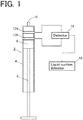
- Fig. 1 shows a schematic configuration of a device having a function of detecting the presence or absence of a liquid suctioned by a syringe pump.
- a syringe pump 2 includes: a tubular syringe 4 having a suction/discharge port 10 at a distal end of the syringe 4 for sucking and discharging a liquid; a piston 6 being operable in the syringe 4 in an axial direction (a vertical direction in the drawing) of the syringe 4; and a piston rod 8 for holding the piston 6 at a distal end of the piston rod 8 and for driving the piston 6.
- a pair of electrodes 12a, 12b is provided to the syringe 4 of the syringe pump 2.
- the pair of electrodes 12a, 12b are provided to an outer peripheral surface of the syringe 4 of the syringe pump 2 on a distal end side of the syringe 4 in a spaced-apart manner from each other in an axial direction of the syringe 4.
- the pair of electrodes 12a, 12b is each formed of, for example, an aluminum thin film wound around the outer peripheral surface of the syringe pump 2.
- a detector 14 is electrically connected to the pair of electrodes 12a, 12b.
- the detector 14 detects a value of electrostatic capacitance between the pair of electrodes 12a, 12b or a value (for example, reactance or impedance) that changes corresponding to a change in electrostatic capacitance.
- a value of electrostatic capacitance between the pair of electrodes 12a, 12b or a value (for example, reactance or impedance) that changes corresponding to a change in electrostatic capacitance.
- an LCR meter can be used.
- the pair of electrodes 12a, 12b may be configured such that electrostatic capacitance between the electrodes 12a, 12b changes between when the suction of a liquid into the syringe 4 is performed and when the suction of the liquid into the syringe 4 is not performed, that is, between when a liquid phase exists between the electrodes 12a, 12b and when the liquid phase does not exist between the electrodes 12a, 12b.
- the water quality analyzer further includes a liquid suction detector 16.
- the liquid suction detector 16 is configured to detect that a liquid has been suctioned by the syringe pump 2 based on a change in a detection signal transmitted from the detector 14.
- the liquid suction detector 16 is a function realized by an arithmetic element such as a central processing unit (CPU) and a predetermined program executed by the arithmetic element.
- the liquid suction detector 16 is configured to detect a change in electrostatic capacitance between the pair of electrodes 12a, 12b based on a change in a detection signal value of the detector 14, and is configured to detect that the liquid has been suctioned by the syringe pump 2 based on the change in electrostatic capacitance between the pair of electrodes 12a, 12b.
- a method is considered where a detection signal value of the detector 14 is compared with a preset threshold, and it is detected that the liquid is suctioned into the syringe 4 of the syringe pump 2 when the detection signal value exceeds the threshold.
- the water quality analyzer which is an embodiment of a device having a function of detecting a liquid suctioned by the syringe pump 2 will be described with reference to Fig. 2 .
- the water quality analyzer of this embodiment mainly includes the syringe pump 2, two multi-port valves 104, 106, a reactor 108, a measurement unit 110, and an arithmetic control device 120.
- a suction/discharge port of the syringe pump 2 is connected to a center port of the multi-port valve 104 described later.
- a pump 20 for stirring is connected to the cylinder of the syringe pump 2 through a flow path, and liquid can be stirred in the syringe pump 2 by air supplied by the pump 20.
- the syringe pump 2 is driven by a syringe pump driver 18 which includes a stepping motor and the like.
- the multi-port valve 104 has one center port and a plurality of select ports, and the center port can be selectively connected to any one of the select ports.
- One select port of the multi-port valve 104 is connected to a center port of the multi-port valve 106 through a flow path.
- the other select ports of the multi-port valve 104 are ports to which containers that store reagents (1) to (6) are connected respectively.
- a sodium hydroxide solution is provided as the reagent (1)
- a potassium persulfate solution is provided as the reagent (2)
- a hydrochloric acid solution is provided as the reagent (3)
- a sulfuric acid solution is provided as the reagent (4)
- a molybdic acid solution is provided as the reagent (5)
- an ascorbic acid solution is provided as the reagent (6).
- the arithmetic control device 120 that controls the operation of the water quality analyzer stores the select ports of the multi-port valve 4 and the reagents (1) to (6) to be connected to the select ports in a state where the select ports and the reagents (1) to (6) correspond to each other.
- the multi-port valve 106 also has one center port and a plurality of select ports, and the center port is selectively connected to any one of the select ports.
- One select port of the multi-port valve 106 is connected to the reactor 108 through a flow path, and another select port of the multi-port valve 106 is connected to an inlet of a measurement cell 112 of the measurement unit 110 through a flow path.
- a water sampling tube for sampling sample water and flow paths communicating with containers which respectively store a spun liquid, a diluted liquid, and a standard liquid are connected.
- the reactor 108 is provided for applying an oxidation treatment to a sample.
- the reactor 108 has an inner space for storing liquid, and a lighting portion of an ultraviolet ray lamp 109 is inserted into the inner space.
- the oxidation treatment of a sample is a treatment where a compound to be measured in the sample is oxidatively decomposed by irradiating ultraviolet rays to the sample to which an oxidizing agent (for example, a potassium persulfate solution) is added while supplying oxygen gas or air into the inner space of the reactor 108 under a predetermined temperature condition (for example, 95°C) .
- an oxidizing agent for example, a potassium persulfate solution
- the measurement unit 110 includes the measurement cell 112, a light source 114, and a light detection element 116.
- An outlet of the measurement cell 112 communicates with a drain.
- the light source 114 generates light having a measurement wavelength (for example, 220 nm) and irradiates the light toward the measurement cell 112.
- a laser element can be used.
- the light detection element 116 is provided for detecting the intensity of light from the light source 114 that has passed through the measurement cell 112.
- a photodiode can be used as the light detection element 116.
- Sample water to which oxidizing treatment is already applied or any one of the reagents (1) to (6) is selectively transferred to the measurement cell 112 of the measurement unit 110 by the syringe pump 2.
- the arithmetic control device 120 is provided for performing an operation control and arithmetic processing of the water quality analyzer.
- a dedicated computer or a general-purpose personal computer can be used as the arithmetic control device 120.
- a detection signal from the detector 14 that detects a value of electrostatic capacitance between the pair of electrodes 12a, 12b provided to the syringe 4 of the syringe pump 2 or a value that changes corresponding to a change in electrostatic capacitance is taken into the arithmetic control device 120.
- the arithmetic control device 120 includes the liquid suction detector 16 that is configured to detect the suction of a liquid by the syringe pump 2 based on a change in a detection signal of the detector 14.
- the liquid suction detector 16 is realized when a CPU that is incorporated in the arithmetic control device 120 executes a predetermined program.
- the arithmetic control device 120 controls an operation of the syringe pump driver 18.
- the arithmetic control device 120 can check whether or not a liquid suctioned by the syringe pump 2 is actually performed by taking in a detection signal from the detector 14 at a timing that the syringe pump 2 is operated so as to perform a suction operation of the liquid. That is, when the liquid suction detector 16 does not detect the suction of a liquid by the syringe pump 2 even though a signal to request the syringe pump 2 to execute the suction of the liquid is transmitted to the syringe pump driver 18, the arithmetic control device 120 can detect that an error has occurred in the suction of the liquid by the syringe pump 2.
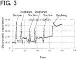
- Fig. 3 is a graph illustrating an example of a relationship between an operation of the syringe pump 2 and a detection signal value (electrostatic capacitance) of the detector 14.
- peaks appear in the detection signal of the detector 14 at timings when the syringe pump 2 suctions and discharges the liquid.
- the detection signal has a peak shape because the syringe pump 2 is operated such that air is suctioned after a predetermined amount of liquid is suctioned into the syringe of the syringe pump 2 so that a liquid phase temporarily passes through the space between the pair of electrodes 12a, 12b.
- the detection signal of the detector 14 is in an elevated state also during a period where bubbling is performed by feeding air into the syringe pump 2 by the pump 20 after the liquid is suctioned into the syringe pump 2. This is because a splash of liquid reaches a space between the pair of electrodes 12a, 12b during bubbling and hence, electrostatic capacitance between the pair of electrodes 12a, 12b increases.
- liquid suction detector 16 to a device such as the water quality analyzer that uses the syringe pump 2, it is possible to monitor whether or not an operation such as a suction operation or a discharge operation of liquid by the syringe pump 2 is normally performed.
Landscapes
- Chemical & Material Sciences (AREA)
- Health & Medical Sciences (AREA)
- Life Sciences & Earth Sciences (AREA)
- General Health & Medical Sciences (AREA)
- Physics & Mathematics (AREA)
- Immunology (AREA)
- Pathology (AREA)
- Biochemistry (AREA)
- Analytical Chemistry (AREA)
- General Physics & Mathematics (AREA)
- Chemical Kinetics & Catalysis (AREA)
- Engineering & Computer Science (AREA)
- Electrochemistry (AREA)
- Food Science & Technology (AREA)
- Medicinal Chemistry (AREA)
- Electromagnetism (AREA)
- Toxicology (AREA)
- Organic Chemistry (AREA)
- Automatic Analysis And Handling Materials Therefor (AREA)
- Sampling And Sample Adjustment (AREA)
- Investigating Or Analyzing Materials By The Use Of Electric Means (AREA)
Abstract
Description
- The present invention relates to a method for detecting the presence/absence of a liquid suctioned by a syringe pump, and a device with a syringe pump.
- In a water quality analyzer such as a total organic carbon measurement device (TOC meter) or a total phosphorus measurement device (TP meter), a syringe pump is used to transfer, besides sample water, a liquid such as a cleaning liquid, an oxidizing agent or a reducing agent (see, for example,
- Patent Document 1).
- Patent Document 1:
Japanese Patent Laid-Open No. 2018 059788 - In the water quality analyzer as described above, measurement cannot be normally performed unless suction and discharge of a liquid by the syringe pump are normally performed. When sampling of the sample water is not normally performed, a measured value obtained after such sampling exhibits an abnormal value. In this case, however, it is not easy to identify that such an abnormal measured value is exhibited due to a failure in sampling water by the syringe pump.
- As a cause of the failure in water sampling by the syringe pump, in addition to a case where the syringe pump is not normally operated, a case is considered where, although the syringe pump is normally operated, a liquid is not normally suctioned into the syringe pump. Whether or not the syringe pump is operated normally can be detected by monitoring driving of a motor that operates the syringe pump. On the other hand, since it is difficult to insert a liquid level sensor into a syringe of the syringe pump, it is impossible to detect by the liquid level sensor whether or not the syringe pump has actually suctioned a liquid normally.
- In view of such circumstances, it is an object of the present invention to provide a technique by which the presence or absence of a liquid suctioned by a syringe pump can be automatically detected.
- A method according to the present invention includes, in a following order: a step of detecting a change in electrostatic capacitance between a pair of electrodes provided to a syringe, having a tubular shape in which a piston is moved in an axial direction of the syringe, of a syringe pump; and a step of detecting that liquid suction has been performed by the syringe pump based on the change in the electrostatic capacitance.
- A liquid and air differ from each other in dielectric constant (a dielectric constant of air being about 1/80 of a dielectric constant of water). Accordingly, an amount of electrostatic capacitance in a space in the syringe largely differs between a case where a liquid phase exists in the space and a case where an air phase exists in the space. Therefore, it can be detected that liquid suction has been performed by the syringe pump by detecting a change in electrostatic capacitance in the space in the syringe.
- In the first configuration of the method according to the present invention, in the step of detecting the liquid suction, it is detected that the liquid suction has been performed by the syringe pump when a value of the electrostatic capacitance exceeds a preset threshold, or when a value that changes in conjunction with the change in the electrostatic capacitance exceeds a preset threshold. With such a configuration, it can be easily detected that liquid suction has been performed by the syringe pump.
- In the second configuration of the method according to the present invention, the pair of electrodes is attached on an outer peripheral surface of the syringe in a spaced-apart manner from each other in the axial direction of the syringe. With such a configuration, it is possible to realize the detection of the suction of the liquid by the syringe pump with a simple and inexpensive configuration.
- The first configuration and the second configuration can be combined with each other.
- A device according to the present invention includes a syringe pump, a pair of electrodes, a detector, and a liquid suction detector. In the syringe pump, a piston is moved in a tubular syringe in an axial direction of the syringe. The pair of electrodes is provided to the syringe so that electrostatic capacitance between the pair of electrodes changes between when the liquid suction into the syringe is performed and when the liquid suction into the syringe is not performed. The detector detects a value of electrostatic capacitance between the pair of electrodes or a value that changes in conjunction with a change in the electrostatic capacitance. The liquid suction detector detects that the liquid suction has been performed by the syringe pump based on the change in electrostatic capacitance between the pair of electrodes detected by the detector or the change in the value that changes in conjunction with the change in the electrostatic capacitance.
- That is, the device according to the present invention has a function of automatically detecting the presence or absence of liquid suction by the syringe pump based on a change in electrostatic capacitance between the pair of electrodes provided to the syringe of the syringe pump.
- In the first configuration of the device according to the present invention, the pair of electrodes is attached on an outer peripheral surface of the syringe in a spaced-apart manner from each other in an axial direction of the syringe.
- In the second configuration of the device according to the present invention, the liquid suction detector detects that the liquid has been suctioned by the syringe pump when the value of electrostatic capacitance between the pair of electrodes exceeds a preset threshold, or when the value that changes in conjunction with the change in the electrostatic capacitance exceeds a preset threshold. With such a configuration, it can be easily detected that liquid suction has been performed by the syringe pump.
- In the third configuration of the device according to the present invention, the pair of electrodes includes aluminum thin films wrapped around an outer peripheral surface of the syringe at two positions. With such a configuration, it is possible to realize a function of detecting the suction of the liquid by the syringe pump with a simple and inexpensive configuration.
- The above first to third configurations of the device according to the present invention can be combined with each other.
- According to the method and the device of the present invention, it is possible to automatically detect the presence or absence of a liquid suctioned by the syringe pump.
-
-
Fig. 1 is a schematic configurational view illustrating an embodiment of a water quality analyzer. -
Fig. 2 is a flowchart illustrating an example of a reagent determination operation of the embodiment. -
Fig. 3 is a graph illustrating a relationship between an operation of a syringe pump and a detection signal (electrostatic capacitance) of a detector. - Hereinafter, an embodiment of a method of detecting the presence or absence of a liquid suctioned by a syringe pump and a device having a function of detecting the presence or absence of a liquid suctioned by the syringe pump will be described with reference to the drawings.
-
Fig. 1 shows a schematic configuration of a device having a function of detecting the presence or absence of a liquid suctioned by a syringe pump. - A
syringe pump 2 includes: atubular syringe 4 having a suction/discharge port 10 at a distal end of thesyringe 4 for sucking and discharging a liquid; apiston 6 being operable in thesyringe 4 in an axial direction (a vertical direction in the drawing) of thesyringe 4; and apiston rod 8 for holding thepiston 6 at a distal end of thepiston rod 8 and for driving thepiston 6. - A pair of
electrodes syringe 4 of thesyringe pump 2. The pair ofelectrodes syringe 4 of thesyringe pump 2 on a distal end side of thesyringe 4 in a spaced-apart manner from each other in an axial direction of thesyringe 4. The pair ofelectrodes syringe pump 2. Adetector 14 is electrically connected to the pair ofelectrodes detector 14 detects a value of electrostatic capacitance between the pair ofelectrodes detector 14, an LCR meter can be used. The pair ofelectrodes electrodes syringe 4 is performed and when the suction of the liquid into thesyringe 4 is not performed, that is, between when a liquid phase exists between theelectrodes electrodes - The water quality analyzer further includes a
liquid suction detector 16. Theliquid suction detector 16 is configured to detect that a liquid has been suctioned by thesyringe pump 2 based on a change in a detection signal transmitted from thedetector 14. Theliquid suction detector 16 is a function realized by an arithmetic element such as a central processing unit (CPU) and a predetermined program executed by the arithmetic element. - In a state where no liquid is suctioned into the
syringe 4, an air layer exists in a space in thesyringe 4 formed between the pair ofelectrodes syringe 4 so that the space in thesyringe 4 between the pair ofelectrodes electrodes liquid suction detector 16 is configured to detect a change in electrostatic capacitance between the pair ofelectrodes detector 14, and is configured to detect that the liquid has been suctioned by thesyringe pump 2 based on the change in electrostatic capacitance between the pair ofelectrodes - As the method of detecting that a liquid has been suctioned by the
syringe pump 2 based on a change in a detection signal value of thedetector 14, a method is considered where a detection signal value of thedetector 14 is compared with a preset threshold, and it is detected that the liquid is suctioned into thesyringe 4 of thesyringe pump 2 when the detection signal value exceeds the threshold. - Next, the water quality analyzer which is an embodiment of a device having a function of detecting a liquid suctioned by the
syringe pump 2 will be described with reference toFig. 2 . - The water quality analyzer of this embodiment mainly includes the
syringe pump 2, twomulti-port valves reactor 108, ameasurement unit 110, and anarithmetic control device 120. - A suction/discharge port of the
syringe pump 2 is connected to a center port of themulti-port valve 104 described later. Apump 20 for stirring is connected to the cylinder of thesyringe pump 2 through a flow path, and liquid can be stirred in thesyringe pump 2 by air supplied by thepump 20. Thesyringe pump 2 is driven by asyringe pump driver 18 which includes a stepping motor and the like. - The
multi-port valve 104 has one center port and a plurality of select ports, and the center port can be selectively connected to any one of the select ports. One select port of themulti-port valve 104 is connected to a center port of themulti-port valve 106 through a flow path. The other select ports of themulti-port valve 104 are ports to which containers that store reagents (1) to (6) are connected respectively. - In this example, a sodium hydroxide solution is provided as the reagent (1), a potassium persulfate solution is provided as the reagent (2), a hydrochloric acid solution is provided as the reagent (3), a sulfuric acid solution is provided as the reagent (4), a molybdic acid solution is provided as the reagent (5), and an ascorbic acid solution is provided as the reagent (6). The
arithmetic control device 120 that controls the operation of the water quality analyzer stores the select ports of themulti-port valve 4 and the reagents (1) to (6) to be connected to the select ports in a state where the select ports and the reagents (1) to (6) correspond to each other. - The
multi-port valve 106 also has one center port and a plurality of select ports, and the center port is selectively connected to any one of the select ports. One select port of themulti-port valve 106 is connected to thereactor 108 through a flow path, and another select port of themulti-port valve 106 is connected to an inlet of ameasurement cell 112 of themeasurement unit 110 through a flow path. To other select ports of themulti-port valve 106, a water sampling tube for sampling sample water, and flow paths communicating with containers which respectively store a spun liquid, a diluted liquid, and a standard liquid are connected. - The
reactor 108 is provided for applying an oxidation treatment to a sample. Thereactor 108 has an inner space for storing liquid, and a lighting portion of anultraviolet ray lamp 109 is inserted into the inner space. The oxidation treatment of a sample is a treatment where a compound to be measured in the sample is oxidatively decomposed by irradiating ultraviolet rays to the sample to which an oxidizing agent (for example, a potassium persulfate solution) is added while supplying oxygen gas or air into the inner space of thereactor 108 under a predetermined temperature condition (for example, 95°C) . - The
measurement unit 110 includes themeasurement cell 112, alight source 114, and alight detection element 116. An outlet of themeasurement cell 112 communicates with a drain. Thelight source 114 generates light having a measurement wavelength (for example, 220 nm) and irradiates the light toward themeasurement cell 112. As thelight source 114, for example, a laser element can be used. Thelight detection element 116 is provided for detecting the intensity of light from thelight source 114 that has passed through themeasurement cell 112. As thelight detection element 116, for example, a photodiode can be used. - Sample water to which oxidizing treatment is already applied or any one of the reagents (1) to (6) is selectively transferred to the
measurement cell 112 of themeasurement unit 110 by thesyringe pump 2. - The
arithmetic control device 120 is provided for performing an operation control and arithmetic processing of the water quality analyzer. As thearithmetic control device 120, a dedicated computer or a general-purpose personal computer can be used. A detection signal from thedetector 14 that detects a value of electrostatic capacitance between the pair ofelectrodes syringe 4 of thesyringe pump 2 or a value that changes corresponding to a change in electrostatic capacitance is taken into thearithmetic control device 120. Thearithmetic control device 120 includes theliquid suction detector 16 that is configured to detect the suction of a liquid by thesyringe pump 2 based on a change in a detection signal of thedetector 14. Theliquid suction detector 16 is realized when a CPU that is incorporated in thearithmetic control device 120 executes a predetermined program. - The
arithmetic control device 120 controls an operation of thesyringe pump driver 18. Thearithmetic control device 120 can check whether or not a liquid suctioned by thesyringe pump 2 is actually performed by taking in a detection signal from thedetector 14 at a timing that thesyringe pump 2 is operated so as to perform a suction operation of the liquid. That is, when theliquid suction detector 16 does not detect the suction of a liquid by thesyringe pump 2 even though a signal to request thesyringe pump 2 to execute the suction of the liquid is transmitted to thesyringe pump driver 18, thearithmetic control device 120 can detect that an error has occurred in the suction of the liquid by thesyringe pump 2. -
Fig. 3 is a graph illustrating an example of a relationship between an operation of thesyringe pump 2 and a detection signal value (electrostatic capacitance) of thedetector 14. As can be understood fromFig. 3 , peaks appear in the detection signal of thedetector 14 at timings when thesyringe pump 2 suctions and discharges the liquid. The detection signal has a peak shape because thesyringe pump 2 is operated such that air is suctioned after a predetermined amount of liquid is suctioned into the syringe of thesyringe pump 2 so that a liquid phase temporarily passes through the space between the pair ofelectrodes detector 14 is in an elevated state also during a period where bubbling is performed by feeding air into thesyringe pump 2 by thepump 20 after the liquid is suctioned into thesyringe pump 2. This is because a splash of liquid reaches a space between the pair ofelectrodes electrodes - In this manner, by providing the
liquid suction detector 16 to a device such as the water quality analyzer that uses thesyringe pump 2, it is possible to monitor whether or not an operation such as a suction operation or a discharge operation of liquid by thesyringe pump 2 is normally performed. -
- 2:
- Syringe pump
- 4:
- Cylinder
- 6:
- Piston
- 8:
- Piston rod
- 10:
- Suction/discharge port
- 12a, 12b:
- Electrode
- 14:
- Detector
- 16:
- Liquid suction detector
Claims (7)
- A method comprising, in a following order:a step of detecting a change in electrostatic capacitance between a pair of electrodes provided to a syringe, having a tubular shape in which a piston is moved in an axial direction of the syringe, of a syringe pump; anda step of detecting that liquid suction has been performed by the syringe pump based on the change in the electrostatic capacitance.
- The method according to claim 1, wherein in the step of detecting the liquid suction, it is detected that the liquid suction has been performed by the syringe pump when a value of the electrostatic capacitance exceeds a preset threshold, or when a value that changes in conjunction with the change in the electrostatic capacitance exceeds a preset threshold.
- The method according to claim 1, wherein the pair of electrodes is attached on an outer peripheral surface of the syringe in a spaced-apart manner from each other in the axial direction of the syringe.
- A device comprising:a syringe pump comprising a syringe having a tubular shape and a piston operated in the syringe in an axial direction of the syringe;a pair of electrodes provided to the syringe, the pair of electrodes is provided so that electrostatic capacitance between the pair of electrodes changes between when liquid suction into the syringe has been performed and when the liquid suction into the syringe has not been performed; anda detector configured to detect a value of electrostatic capacitance between the pair of electrodes or a value that changes in conjunction with a change in the electrostatic capacitance; anda liquid suction detector configured to detect that the liquid suction by the syringe pump has been performed based on the change in electrostatic capacitance between the pair of electrodes or the change in the value that changes in conjunction with the change in the electrostatic capacitance.
- The device according to claim 4, wherein the pair of electrodes is attached on an outer peripheral surface of the syringe in a spaced-apart manner from each other in an axial direction of the syringe.
- The device according to claim 4, wherein the liquid suction detector is configured to detect that the liquid has been suctioned by the syringe pump when the value of electrostatic capacitance between the pair of electrodes exceeds a preset threshold, or when the value that changes in conjunction with the change in the electrostatic capacitance exceeds a preset threshold.
- The device according to claim 4, wherein the pair of electrodes comprises aluminum thin films wrapped around an outer peripheral surface of the syringe at two positions.
Applications Claiming Priority (2)
| Application Number | Priority Date | Filing Date | Title |
|---|---|---|---|
| JP2018244142 | 2018-12-27 | ||
| PCT/JP2019/023813 WO2020136944A1 (en) | 2018-12-27 | 2019-06-17 | Method for detecting presence/absence of liquid suctioned by syringe pump, and device with syringe pump |
Publications (2)
| Publication Number | Publication Date |
|---|---|
| EP3904857A1 true EP3904857A1 (en) | 2021-11-03 |
| EP3904857A4 EP3904857A4 (en) | 2022-08-31 |
Family
ID=71127075
Family Applications (1)
| Application Number | Title | Priority Date | Filing Date |
|---|---|---|---|
| EP19902928.1A Pending EP3904857A4 (en) | 2018-12-27 | 2019-06-17 | METHOD FOR DETECTING THE PRESENCE/ABSENCE OF LIQUID DRAGGED BY A SYRINGE PUMP AND DEVICE WITH A SYRINGE PUMP |
Country Status (5)
| Country | Link |
|---|---|
| US (1) | US12216083B2 (en) |
| EP (1) | EP3904857A4 (en) |
| JP (1) | JP7207432B2 (en) |
| CN (1) | CN113227578B (en) |
| WO (1) | WO2020136944A1 (en) |
Families Citing this family (1)
| Publication number | Priority date | Publication date | Assignee | Title |
|---|---|---|---|---|
| WO2025211224A1 (en) * | 2024-04-04 | 2025-10-09 | 株式会社島津製作所 | Water quality analyzer |
Family Cites Families (19)
| Publication number | Priority date | Publication date | Assignee | Title |
|---|---|---|---|---|
| JPS57153221A (en) | 1981-03-17 | 1982-09-21 | Sumitomo Electric Ind Ltd | Water level alarm device |
| DE3923079A1 (en) * | 1989-07-13 | 1991-01-24 | Fresenius Ag | Measuring level of electrically conducting liquid - has measuring of infusion liquid or blood from change in capacitance of electrodes in measurement liquid |
| DE4203638A1 (en) * | 1992-02-08 | 1993-08-12 | Boehringer Mannheim Gmbh | LIQUID TRANSFER DEVICE FOR AN ANALYZER |
| JPH06194212A (en) | 1992-12-22 | 1994-07-15 | Miyawaki:Kk | Electrostatic capacitance sensor |
| EP0694784B1 (en) * | 1994-07-28 | 2002-02-27 | Hitachi, Ltd. | Liquid sampling apparatus |
| EP1103796B1 (en) * | 1999-11-19 | 2003-10-08 | ESEC Trading S.A. | Sensor for the detection of a predetermined level in a container |
| EP1436586A2 (en) | 2001-10-19 | 2004-07-14 | MonoGen, Inc. | Automated system and method for processing multiple liquid-based specimens |
| WO2006080761A1 (en) | 2004-10-13 | 2006-08-03 | Centennial Technology Company | Automatic chlorophyll analyzer and analytical method |
| JP2007064759A (en) * | 2005-08-30 | 2007-03-15 | Hoyutec Kk | Fluid transfer device |
| JP4966913B2 (en) * | 2007-05-15 | 2012-07-04 | 株式会社日立ハイテクノロジーズ | Liquid dispensing device |
| JP5658566B2 (en) * | 2007-09-29 | 2015-01-28 | イーアイ・スペクトラ・エルエルシー | Instrument pipette tip |
| RU2605151C2 (en) | 2011-07-18 | 2016-12-20 | Либэль-Фларшайм Кампани ЭлЭлСи | Injection system with capacitive measurement |
| JP2013193319A (en) | 2012-03-19 | 2013-09-30 | Ulvac Japan Ltd | Liquid amount detecting device, and liquid supply device |
| AT513452B1 (en) * | 2012-10-05 | 2014-08-15 | Ait Austrian Inst Technology | Dispensing device for medicaments |
| JP6965502B2 (en) | 2016-08-30 | 2021-11-10 | 株式会社島津製作所 | Water quality analyzer |
| JP6721477B2 (en) * | 2016-09-29 | 2020-07-15 | テルモ株式会社 | Chemical dosing device |
| JP6665751B2 (en) * | 2016-10-05 | 2020-03-13 | 株式会社島津製作所 | Water quality analyzer |
| US10627384B1 (en) * | 2019-03-07 | 2020-04-21 | Shimadzu Corporation | Water quality analyzer |
| US20220299539A1 (en) * | 2019-12-05 | 2022-09-22 | Hitachi High-Tech Corporation | Automatic analyzer |
-
2019
- 2019-06-17 EP EP19902928.1A patent/EP3904857A4/en active Pending
- 2019-06-17 US US17/418,135 patent/US12216083B2/en active Active
- 2019-06-17 JP JP2020562314A patent/JP7207432B2/en active Active
- 2019-06-17 CN CN201980086424.5A patent/CN113227578B/en active Active
- 2019-06-17 WO PCT/JP2019/023813 patent/WO2020136944A1/en not_active Ceased
Also Published As
| Publication number | Publication date |
|---|---|
| US12216083B2 (en) | 2025-02-04 |
| CN113227578B (en) | 2023-02-21 |
| US20220099626A1 (en) | 2022-03-31 |
| CN113227578A (en) | 2021-08-06 |
| JP7207432B2 (en) | 2023-01-18 |
| EP3904857A4 (en) | 2022-08-31 |
| WO2020136944A1 (en) | 2020-07-02 |
| JPWO2020136944A1 (en) | 2021-10-28 |
Similar Documents
| Publication | Publication Date | Title |
|---|---|---|
| US10295458B2 (en) | Analytical device for determining a digestion parameter of a liquid sample | |
| WO2019014942A1 (en) | Sample analyzer and sample monitoring method | |
| EP3101431B1 (en) | Automatic analytical apparatus | |
| US20110184570A1 (en) | Reagent preparing apparatus | |
| CN111766208B (en) | An intelligent multi-parameter water quality analyzer and analysis method | |
| JP6881189B2 (en) | Total phosphorus measuring device | |
| US12216083B2 (en) | Method for detecting presence/absence of liquid suctioned by syringe pump, and device with syringe pump | |
| CN113008883A (en) | Method for determining a parameter based on the concentration of at least one analyte in a sample liquid | |
| US9176046B2 (en) | Analyzing device | |
| JP2006098226A (en) | Anomaly detection method for syringe pump, liquid suction/discharge apparatus, and biochemical analyzer | |
| CN110006699B (en) | High-precision quantitative device and quantitative method for online analysis of water quality | |
| US20130071939A1 (en) | Urine analysis method, device thereof, program used in urine analysis method, and storage medium thereof | |
| WO2007132903A1 (en) | Method for automatically identifying control liquid | |
| TW202138061A (en) | Systems for monitoring fluidics in reagent cartridges and related methods | |
| JP6965502B2 (en) | Water quality analyzer | |
| CN112129913A (en) | Water quality analyzer, water quality online monitoring system and quantitative method for water quality analyzer | |
| EP2959286A1 (en) | Device and method for measuring the oxygen content in welding processes | |
| EP3910330B1 (en) | Water quality analyzer | |
| CN117571946A (en) | Multi-parameter water quality online monitoring system and method | |
| US20180011005A1 (en) | Apparatus for inline trace analysis of a liquid | |
| WO2025112742A1 (en) | Medical analyzer and method for operating the medical analyzer | |
| US12480928B2 (en) | Total organic carbon measurement method and total organic carbon measurement device | |
| JP2020063998A (en) | Water quality analyzer and ultraviolet lamp deterioration determination method | |
| KR20160093771A (en) | optical dissolved oxygen sensor | |
| CN117191481A (en) | Water quality analyzer liquid sampling device capable of detecting existence of reagent |
Legal Events
| Date | Code | Title | Description |
|---|---|---|---|
| STAA | Information on the status of an ep patent application or granted ep patent |
Free format text: STATUS: THE INTERNATIONAL PUBLICATION HAS BEEN MADE |
|
| PUAI | Public reference made under article 153(3) epc to a published international application that has entered the european phase |
Free format text: ORIGINAL CODE: 0009012 |
|
| STAA | Information on the status of an ep patent application or granted ep patent |
Free format text: STATUS: REQUEST FOR EXAMINATION WAS MADE |
|
| 17P | Request for examination filed |
Effective date: 20210722 |
|
| AK | Designated contracting states |
Kind code of ref document: A1 Designated state(s): AL AT BE BG CH CY CZ DE DK EE ES FI FR GB GR HR HU IE IS IT LI LT LU LV MC MK MT NL NO PL PT RO RS SE SI SK SM TR |
|
| DAV | Request for validation of the european patent (deleted) | ||
| DAX | Request for extension of the european patent (deleted) | ||
| RIN1 | Information on inventor provided before grant (corrected) |
Inventor name: YAHATA, MASAHITO |
|
| A4 | Supplementary search report drawn up and despatched |
Effective date: 20220729 |
|
| RIC1 | Information provided on ipc code assigned before grant |
Ipc: A61M 5/32 20060101ALI20220725BHEP Ipc: A61M 5/178 20060101ALI20220725BHEP Ipc: B01L 3/06 20060101ALI20220725BHEP Ipc: G01M 13/00 20190101ALI20220725BHEP Ipc: B01J 4/02 20060101ALI20220725BHEP Ipc: G01N 1/00 20060101AFI20220725BHEP |
|
| STAA | Information on the status of an ep patent application or granted ep patent |
Free format text: STATUS: EXAMINATION IS IN PROGRESS |
|
| 17Q | First examination report despatched |
Effective date: 20230904 |