EP3904851A1 - Fabry-perot based advance pneumatic fire/overheat detector - Google Patents
Fabry-perot based advance pneumatic fire/overheat detector Download PDFInfo
- Publication number
- EP3904851A1 EP3904851A1 EP21169729.7A EP21169729A EP3904851A1 EP 3904851 A1 EP3904851 A1 EP 3904851A1 EP 21169729 A EP21169729 A EP 21169729A EP 3904851 A1 EP3904851 A1 EP 3904851A1
- Authority
- EP
- European Patent Office
- Prior art keywords
- mirror
- lens
- fire
- hydrogen
- diaphragm
- Prior art date
- Legal status (The legal status is an assumption and is not a legal conclusion. Google has not performed a legal analysis and makes no representation as to the accuracy of the status listed.)
- Granted
Links
Images

Classifications
-
- G—PHYSICS
- G01—MEASURING; TESTING
- G01K—MEASURING TEMPERATURE; MEASURING QUANTITY OF HEAT; THERMALLY-SENSITIVE ELEMENTS NOT OTHERWISE PROVIDED FOR
- G01K5/00—Measuring temperature based on the expansion or contraction of a material
- G01K5/48—Measuring temperature based on the expansion or contraction of a material the material being a solid
-
- G—PHYSICS
- G01—MEASURING; TESTING
- G01K—MEASURING TEMPERATURE; MEASURING QUANTITY OF HEAT; THERMALLY-SENSITIVE ELEMENTS NOT OTHERWISE PROVIDED FOR
- G01K5/00—Measuring temperature based on the expansion or contraction of a material
- G01K5/28—Measuring temperature based on the expansion or contraction of a material the material being a gas
-
- G—PHYSICS
- G01—MEASURING; TESTING
- G01K—MEASURING TEMPERATURE; MEASURING QUANTITY OF HEAT; THERMALLY-SENSITIVE ELEMENTS NOT OTHERWISE PROVIDED FOR
- G01K15/00—Testing or calibrating of thermometers
- G01K15/007—Testing
-
- G—PHYSICS
- G01—MEASURING; TESTING
- G01L—MEASURING FORCE, STRESS, TORQUE, WORK, MECHANICAL POWER, MECHANICAL EFFICIENCY, OR FLUID PRESSURE
- G01L9/00—Measuring steady of quasi-steady pressure of fluid or fluent solid material by electric or magnetic pressure-sensitive elements; Transmitting or indicating the displacement of mechanical pressure-sensitive elements, used to measure the steady or quasi-steady pressure of a fluid or fluent solid material, by electric or magnetic means
- G01L9/0041—Transmitting or indicating the displacement of flexible diaphragms
- G01L9/0076—Transmitting or indicating the displacement of flexible diaphragms using photoelectric means
- G01L9/0077—Transmitting or indicating the displacement of flexible diaphragms using photoelectric means for measuring reflected light
- G01L9/0079—Transmitting or indicating the displacement of flexible diaphragms using photoelectric means for measuring reflected light with Fabry-Perot arrangements
-
- G—PHYSICS
- G01—MEASURING; TESTING
- G01M—TESTING STATIC OR DYNAMIC BALANCE OF MACHINES OR STRUCTURES; TESTING OF STRUCTURES OR APPARATUS, NOT OTHERWISE PROVIDED FOR
- G01M3/00—Investigating fluid-tightness of structures
- G01M3/02—Investigating fluid-tightness of structures by using fluid or vacuum
- G01M3/36—Investigating fluid-tightness of structures by using fluid or vacuum by detecting change in dimensions of the structure being tested
-
- G—PHYSICS
- G08—SIGNALLING
- G08B—SIGNALLING SYSTEMS, e.g. PERSONAL CALLING SYSTEMS; ORDER TELEGRAPHS; ALARM SYSTEMS
- G08B17/00—Fire alarms; Alarms responsive to explosion
- G08B17/04—Hydraulic or pneumatic actuation of the alarm, e.g. by change of fluid pressure
Definitions
- the following description relates to a fire or overheat detection system, and more specifically, a fire or overheat detection system that detects when the fire or overheat detection system has a fault.
- Fire or overheat detection systems are used to detect fires or overheat scenarios in engines and turbomachines. To increase the detection of potential fires or overheat scenarios, fire or overheat detection systems are strategically placed around engines. The location of the fire or overheat detection systems ensure that the fire or overheat detection systems quickly and accurately detect a fire or overheat scenario. Present fire or overheat detection systems can become contaminated resulting in false alarms in the field. Additionally, present fire or overheat detection systems are complicated in terms of manufacturing and assembly.
- a fire or overheat detection device in one aspect of the disclosure, includes a diaphragm adjacent a chamber with a gas inside the chamber, wherein the diaphragm contacts the gas.
- the fire or overheat detection system also includes a Fabry-Perot interferometer. At least a portion of the Fabry-Perot interferometer is coupled to the diaphragm via a linkage.
- a light source is configured to direct an input light into the Fabry-Perot interferometer.
- a fire or overheat detection device in another aspect of the disclosure, includes a tube extending from a first end to a second end. The first end of the tube is closed, a diaphragm is connected to the second end and a gas is disposed inside the tube.
- the fire or overheat detection system also includes a light source, a first lens aligned with the light source, and a second lens aligned with the first lens.
- a first mirror is between the first lens and the second lens, and a second mirror is between the first mirror and the second lens.
- a linkage member is connected to the second mirror and the diaphragm.
- the first lens is between the light source and the first mirror.
- the fire or overheat detection system also includes an image sensor. The second lens is between the second mirror and the image sensor.
- a method of operating a fire or overheat detector includes detecting a fire or overheat by expanding a gas inside a chamber to move a diaphragm adjacent the chamber in a first direction.
- a second mirror of a Fabry-Perot interferometer is connected to the diaphragm by a linkage member and moves in the first direction when the diaphragm moves in the first direction.
- the present disclosure relates to a fire or overheat detection system utilizing a chamber of gas, a diaphragm, and a Fabry-Perot interferometer.
- the gas in the chamber expands against the diaphragm when exposed to high temperatures, causing the diaphragm to deflect in a first direction.
- the Fabry-Perot interferometer measures the deflection of the diaphragm in the first direction to detect fire. Should a leak occur in the chamber, the diaphragm will deflect in a second direction.
- the Fabry-Perot interferometer measures the deflection of the diaphragm in the second direction to detect the leak and malfunction of the fire or overheat detection system.
- the fire or overheat detection system will be described below with reference to FIGS 1-4C .
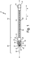
- FIG. 1 is a schematic illustration of fire or overheat detection system 10.
- Fire or overheat detection system 10 includes pneumatic portion 12, Fabry-Perot interferometer 30, and center axis AA.
- Pneumatic portion 12 includes tube 14.
- Tube 14 includes first end 16, second end 18, cap 20, sleeve 22, diaphragm 24, hydrogen-charged core 26, and chamber 28.
- Fabry-Perot interferometer 30 includes enclosure 32, linkage member 34, light source 36, first lens 38, first mirror 40, second mirror 42, second lens 44, screen 46, and image sensor 48.
- Tube 14 extends axially from first end 16 to second end 18.
- Cap 20 seals first end 16 of tube 14.
- Sleeve 22 is attached to second end 18 of tube 14.
- Sleeve 22 retains diaphragm 24.
- Hydrogen-charged core 26 is contained within tube 14 and is aligned axially with center axis AA.
- Chamber 28 surrounds hydrogen-charged core 26 within tube 14.
- the gas within chamber 28 is in fluid communication with diaphragm 24.
- the gas within chamber 28 is helium.
- the gas within chamber 28 can be helium, hydrogen, or any other inert gas with a linear coefficient of thermal expansion.
- Chamber 28 is charged with gas to obtain a set pressure when pneumatic portion 12 is at a pre-determined steady-state temperature.
- diaphragm 24 is configured not to bias in either first direction A or second direction B.
- hydrogen-charged core 26 is heated.
- hydrogen-charged core 26 releases hydrogen gas into chamber 28.
- the additional hydrogen gas from hydrogen-charged core 26 increases the pressure within chamber 28.
- the pressure operates diaphragm 24 and moves diaphragm 24 to bias first direction A.
- hydrogen-charged core 26 absorbs the hydrogen gas in chamber 28, thereby decreasing the pressure within chamber 28 back to the set steady-state pressure.
- diaphragm 24 moves back to a steady-state position. As discussed above, when diaphragm 24 is in a steady-state position, diaphragm 24 does not bias in first direction A nor in second direction B. If chamber 28 leaks gas, the pressure within chamber 28 decreases. As the pressure within chamber 28 decreases, diaphragm 24 actuates to bias and move in second direction B.
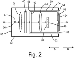
- FIG. 2 is a schematic illustration of Fabry-Perot interferometer 30.
- Enclosure 32 is configured to hermetically seal and insulate Fabry-Perot interferometer 30.
- Enclosure 32 includes first end 50 and second end 52.
- Light source 36 is configured to transmit incident light 37 into enclosure 32 from first end 50 toward second end 52.
- First lens 38 is secured within enclosure 32 so that incident light 37 transmits through center axis AA of first lens 38.
- First lens 38 is spaced axially from first end 50 in direction B toward second end 50.
- First lens 38 is between light source 36 and first mirror 40.
- First mirror 40 is secured within enclosure 32 and is axially spaced from first lens 38 in second direction B.
- First mirror 40 and first lens 38 are axially aligned about center axis AA.
- First mirror 40 is between first lens 38 and second mirror 42.
- Second mirror 42 is secured to linkage member 34 within enclosure 32.
- Second mirror 42, first mirror 40, and first lens 38 are axially aligned on center axis AA.
- Second mirror 42 is between first mirror 40 and second lens 44.
- Second lens 44 is secured within enclosure 32.
- Second lens 44, second mirror 42, first mirror 40, and first lens 38 are axially aligned on center axis AA.
- Second lens 44 is between second mirror 42 and screen 46.
- Screen 46 is secured within container 32.
- Screen 46 is positioned so that the interference pattern of incident light 37 transmitting through first lens 38, first mirror 40, second mirror 42, and second lens 44 is visible on screen 46.
- Image sensor 48 is configured to capture the interference pattern on screen 46.
- second mirror 42 is attached to linkage member 34.
- second mirror 42, second lens 44, and image sensor 46 are all attached to linkage member 34.
- Linkage member 34 comprises first end 54 axially opposite second end 56.
- Linkage member 34 includes base 58 at first end 54 and base 58 is connected to diaphragm 24.
- First bar 60 and second bar 62 extend axially from base 58 to second mirror 42 and connect second mirror 42 to base 58.
- First bar 60 is spaced radially from second bar 62 relative center axis AA.
- Second lens 44, screen 46, and image sensor 48 are positioned between first bar 60 and second bar 62 and positioned axially between second lens 44 and base 58.
- First lens 38 and second lens 44 are configured to gather and focus incident light 37 onto first mirror 40 and screen 46, respectively.
- First lens 38 gathers incident light 37 provided by light source 36 and focuses incident light 37 onto first mirror 40.
- Second lens 44 gathers incident light 37 transmitted through second mirror 42 and focuses incident light 37 on to screen 46.
- First mirror 40 and second mirror 42 are configured to transmit a set amount of incident light 37 and reflect the balance of incident light 37.
- First mirror 40 and second mirror 42 can be coated with a reflective coating to control the amount of light transmitted or reflected.
- first mirror 40 and second mirror 42 can have the same coating, so that first mirror 40 and second mirror 42 each reflect the same amount of light and transmit the same amount of light.
- first mirror 40 and second mirror 42 can each have a unique coating to control the amount of light that each mirror reflects.
- each of first mirror 40 and second mirror 42 reflects 60% to 99% of the light.
- each of first mirror 40 and second mirror 42 reflects 85% to 95% of the light.
- first mirror 40 and second mirror 42 are rectangular prisms.
- first mirror 40 and second mirror 42 can be slightly wedge-shaped to avoid redundant interference patterns.
- FIG. 3 is a schematic illustration showing how refracted light creates an interference pattern through a Fabry-Perot interferometer.
- Fabry-Perot interferometer 30 includes incident angle ⁇ and mirror spacing D.
- incident light 37 contacts first mirror 40 at incident angle ⁇ , and a portion of incident light 37 is reflected off the surface of first mirror 40 at an angle equal to incident angle ⁇ .
- the light that does not reflect off first mirror 40 transmits through first mirror 40.
- the light transmits through first mirror 40 the light refracts due to the refractive index of first mirror 40.
- the angle of the transmitted light is equal to incident angle ⁇ of incident light 37 as entered into first mirror 40.
- the transmitted light hits second mirror 42 at incident angle ⁇ , and a set amount of incident light 37 would reflect off second mirror 42.
- Incident light 37 that does not reflect off second mirror 42 would transmit through second mirror 42.
- Incident light 37 that transmits second mirror 42 would refract according to the refractive index of second mirror 42.
- Incident light 37 that reflects off of second mirror 42 would reflect back to first mirror 40.
- incident light 37 contacts first mirror 40 at incident angle ⁇ .
- Incident light 37 then reflects off first mirror 40 and back toward second mirror 42.
- the reflection of incident light 37 between first mirror 40 and second mirror 42 is an iterative process.
- the iterative process of incident light 37 reflecting between first mirror 40 and second mirror 42 generates an interference pattern depicted on screen 46.
- the interference pattern on screen 46 is then captured by image sensor 48.
- mirror spacing D As second mirror 42 moves in first direction A or second direction B, mirror spacing D, the distance between first mirror 40 and second mirror 42, is changed.
- the interference pattern depicted on screen 46 and captured by image sensor 48 changes.
- the interference pattern is discussed below with reference to FIGS. 4A-4C .
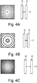
- FIG 4A is a schematic illustration showing a typical interference pattern during normal operating conditions at desirable temperatures.
- First mirror 40 and second mirror 42 are spaced at normal operating mirror spacing D as diaphragm 24 is showing no bias in first direction A or second direction B.
- Fire or overheat detection system 10 is calibrated to recognize the number of bands and the spacing between the bands in the interference pattern of FIG. 4A as a normal operating condition.
- FIG. 4B is a schematic illustration showing a typical interference pattern during fire or high heat operating conditions.
- a fire or high heat occurs proximate fire or overheat detection system 10
- heat is transferred into chamber 24 and causes the pressure inside chamber 24 to increase.
- diaphragm 24 deflects and moves in first direction A.
- linkage member 34 and second mirror 42 also move in first direction A.
- second mirror 42 moving in first direction A
- the distance between first mirror 40 and second mirror 42 is less than normal operating mirror spacing D.
- the decreased distance between first mirror 40 and second mirror 42 decreases the instances of reflection of incident light 37 between first mirror 40 and second mirror 42, which decreases the number of bands to produce the interference pattern of FIG. 4B .
- Fire or overheat detection system 10 is calibrated to recognize the decrease in the number of bands as a leak or fault condition.
- FIG. 4C is a schematic illustration showing a typical interference pattern during a leak or fire or overheat detection system fault.
- gas exits chamber 24 and the pressure inside chamber 24 drops below the steady state pressure.
- diaphragm 24 deflects and moves in second direction B.
- linkage member 34 and second mirror 42 also actuate in second direction B.
- second mirror 42 moving in first direction A the distance between first mirror 40 and second mirror 42 is greater than normal operating mirror spacing D.
- the increased distance between first mirror 40 and second mirror 42 increases the instances of reflection of incident light 37 between first mirror 40 and second mirror 42, which increases the number of bands to produce the interference pattern of FIG. 4C .
- Fire or overheat detection system 10 is calibrated to recognize the increase in the number of bands as a fire or overheat condition.
- a fire or overheat detection device in one aspect of the disclosure, includes a diaphragm adjacent a chamber with a gas inside the chamber, wherein the diaphragm contacts the gas.
- the fire or overheat detection system also includes a Fabry-Perot interferometer. At least a portion of the Fabry-Perot interferometer is coupled to the diaphragm via a linkage.
- a light source is configured to direct an input light into the Fabry-Perot interferometer.
- the fire or overheat detection device of the preceding paragraph can optionally include, additionally and/or alternatively, any one or more of the following features, configurations and/or additional components:
- the chamber may comprise: a tube extending between a first end and a second end; a hydrogen-charged core inside the tube; an end cap connected to the first end of the tube; and a sleeve connected to the second end of the tube, wherein the diaphragm is held within the sleeve.
- the hydrogen-charged core may be configured to release hydrogen from the hydrogen-charged core when the hydrogen-charged core increases in temperature.
- the hydrogen-charged core may be configured to absorb hydrogen when the hydrogen-charged core decreases in temperature.
- the gas may comprise helium.
- the gas may comprise at least one of helium and hydrogen.
- the Fabry-Perot interferometer may include: a first lens, secured within the Fabry-Perot interferometer; a first mirror, secured within the Fabry-Perot interferometer, and axially aligned with the first lens relative a center axis, and wherein the first lens is axially between the light source and the first mirror; a second mirror, coupled to the linkage, and axially aligned with the first lens and the first mirror relative the center axis; a second lens, secured within the Fabry-Perot interferometer, and axially aligned with the first lens, the first mirror, and the second mirror, wherein the first mirror and the second mirror are both axially between the first lens and the second lens, and wherein the second lens is configured to focus the transmitted light onto a screen; and an image sensor secured within the Fabry-Perot interferometer and configured to capture the transmitted light that is focused on the screen, wherein the second lens is axially between the second mirror and the screen.
- a fire or overheat detection device in another aspect of the disclosure, includes a tube extending from a first end to a second end. The first end of the tube is closed, a diaphragm is connected to the second end and a gas is disposed inside the tube.
- the fire or overheat detection system also includes a light source, a first lens aligned with the light source, and a second lens aligned with the first lens.
- a first mirror is between the first lens and the second lens, and a second mirror is between the first mirror and the second lens.
- a linkage member is connected to the second mirror and the diaphragm.
- the first lens is between the light source and the second lens.
- the fire or overheat detection system also includes an image sensor. The second lens is between the second mirror and the image sensor.
- the fire or overheat detection device of the preceding paragraph can optionally include, additionally and/or alternatively, any one or more of the following features, configurations and/or additional components:
- a method of operating a fire or overheat detector includes detecting a fire or overheat by expanding a gas inside a chamber to move a diaphragm adjacent the chamber in a first direction.
- a second mirror of a Fabry-Perot interferometer is connected to the diaphragm by a linkage member and moves in the first direction when the diaphragm moves in the first direction.
- the fire or overheat detection device of the preceding paragraph can optionally include, additionally and/or alternatively, any one or more of the following features, configurations and/or additional components:
Landscapes
- Physics & Mathematics (AREA)
- General Physics & Mathematics (AREA)
- Fluid Mechanics (AREA)
- Business, Economics & Management (AREA)
- Emergency Management (AREA)
- Fire-Detection Mechanisms (AREA)
- Investigating Or Analysing Materials By Optical Means (AREA)
Abstract
Description
- The following description relates to a fire or overheat detection system, and more specifically, a fire or overheat detection system that detects when the fire or overheat detection system has a fault.
- Fire or overheat detection systems are used to detect fires or overheat scenarios in engines and turbomachines. To increase the detection of potential fires or overheat scenarios, fire or overheat detection systems are strategically placed around engines. The location of the fire or overheat detection systems ensure that the fire or overheat detection systems quickly and accurately detect a fire or overheat scenario. Present fire or overheat detection systems can become contaminated resulting in false alarms in the field. Additionally, present fire or overheat detection systems are complicated in terms of manufacturing and assembly.
- In one aspect of the disclosure, a fire or overheat detection device includes a diaphragm adjacent a chamber with a gas inside the chamber, wherein the diaphragm contacts the gas. The fire or overheat detection system also includes a Fabry-Perot interferometer. At least a portion of the Fabry-Perot interferometer is coupled to the diaphragm via a linkage. A light source is configured to direct an input light into the Fabry-Perot interferometer.
- In another aspect of the disclosure, a fire or overheat detection device includes a tube extending from a first end to a second end. The first end of the tube is closed, a diaphragm is connected to the second end and a gas is disposed inside the tube. The fire or overheat detection system also includes a light source, a first lens aligned with the light source, and a second lens aligned with the first lens. A first mirror is between the first lens and the second lens, and a second mirror is between the first mirror and the second lens. A linkage member is connected to the second mirror and the diaphragm. The first lens is between the light source and the first mirror. The fire or overheat detection system also includes an image sensor. The second lens is between the second mirror and the image sensor.
- In another aspect of the disclosure, a method of operating a fire or overheat detector includes detecting a fire or overheat by expanding a gas inside a chamber to move a diaphragm adjacent the chamber in a first direction. A second mirror of a Fabry-Perot interferometer is connected to the diaphragm by a linkage member and moves in the first direction when the diaphragm moves in the first direction.
-
-
FIG. 1 is a schematic illustration of a fire or overheat detection system. -
FIG. 2 is a schematic illustration of a Fabry-Perot interferometer of the fire or overheat detection system fromFIG. 1 . -
FIG. 3 is a schematic illustration showing how reflected and refracted light creates an interference pattern through the Fabry-Perot interferometer ofFIG. 2 . -
FIG 4A is a schematic illustration showing a typical interference pattern during normal operating conditions. -
FIG. 4B is a schematic illustration showing a typical interference pattern during fire or overheat operating conditions. -
FIG. 4C is a schematic illustration showing a typical interference pattern during a leak or fire or overheat detection system fault. - The present disclosure relates to a fire or overheat detection system utilizing a chamber of gas, a diaphragm, and a Fabry-Perot interferometer. The gas in the chamber expands against the diaphragm when exposed to high temperatures, causing the diaphragm to deflect in a first direction. The Fabry-Perot interferometer measures the deflection of the diaphragm in the first direction to detect fire. Should a leak occur in the chamber, the diaphragm will deflect in a second direction. The Fabry-Perot interferometer measures the deflection of the diaphragm in the second direction to detect the leak and malfunction of the fire or overheat detection system. The fire or overheat detection system will be described below with reference to
FIGS 1-4C . -
FIG. 1 is a schematic illustration of fire oroverheat detection system 10. Fire oroverheat detection system 10 includespneumatic portion 12, Fabry-Perot interferometer 30, and center axis AA.Pneumatic portion 12 includestube 14. Tube 14 includesfirst end 16,second end 18,cap 20,sleeve 22,diaphragm 24, hydrogen-chargedcore 26, andchamber 28. Fabry-Perotinterferometer 30 includesenclosure 32,linkage member 34,light source 36,first lens 38,first mirror 40,second mirror 42,second lens 44,screen 46, andimage sensor 48. - Tube 14 extends axially from
first end 16 tosecond end 18.Cap 20 sealsfirst end 16 oftube 14.Sleeve 22 is attached tosecond end 18 oftube 14.Sleeve 22 retainsdiaphragm 24. Hydrogen-chargedcore 26 is contained withintube 14 and is aligned axially with center axis AA.Chamber 28 surrounds hydrogen-chargedcore 26 withintube 14. The gas withinchamber 28 is in fluid communication withdiaphragm 24. In the embodiment ofFIG. 1 , the gas withinchamber 28 is helium. In other embodiments, the gas withinchamber 28 can be helium, hydrogen, or any other inert gas with a linear coefficient of thermal expansion. -
Chamber 28 is charged with gas to obtain a set pressure whenpneumatic portion 12 is at a pre-determined steady-state temperature. Aschamber 28 is at the set pressure,diaphragm 24 is configured not to bias in either first direction A or second direction B. When the temperature of the detection environment increases, hydrogen-chargedcore 26 is heated. When heated, hydrogen-chargedcore 26 releases hydrogen gas intochamber 28. The additional hydrogen gas from hydrogen-chargedcore 26 increases the pressure withinchamber 28. As the pressure increases withinchamber 28, the pressure operatesdiaphragm 24 and movesdiaphragm 24 to bias first direction A. As the system cools, hydrogen-chargedcore 26 absorbs the hydrogen gas inchamber 28, thereby decreasing the pressure withinchamber 28 back to the set steady-state pressure. As the pressure withinchamber 28 approaches the set pressure,diaphragm 24 moves back to a steady-state position. As discussed above, whendiaphragm 24 is in a steady-state position,diaphragm 24 does not bias in first direction A nor in second direction B. Ifchamber 28 leaks gas, the pressure withinchamber 28 decreases. As the pressure withinchamber 28 decreases,diaphragm 24 actuates to bias and move in second direction B. -
FIG. 2 is a schematic illustration of Fabry-Perot interferometer 30.Enclosure 32 is configured to hermetically seal and insulate Fabry-Perot interferometer 30.Enclosure 32 includesfirst end 50 andsecond end 52.Light source 36 is configured to transmitincident light 37 intoenclosure 32 fromfirst end 50 towardsecond end 52.First lens 38 is secured withinenclosure 32 so thatincident light 37 transmits through center axis AA offirst lens 38.First lens 38 is spaced axially fromfirst end 50 in direction B towardsecond end 50.First lens 38 is betweenlight source 36 andfirst mirror 40.First mirror 40 is secured withinenclosure 32 and is axially spaced fromfirst lens 38 in second directionB. First mirror 40 andfirst lens 38 are axially aligned about center axis AA.First mirror 40 is betweenfirst lens 38 andsecond mirror 42.Second mirror 42 is secured tolinkage member 34 withinenclosure 32.Second mirror 42,first mirror 40, andfirst lens 38 are axially aligned on center axis AA.Second mirror 42 is betweenfirst mirror 40 andsecond lens 44.Second lens 44 is secured withinenclosure 32.Second lens 44,second mirror 42,first mirror 40, andfirst lens 38 are axially aligned on center axis AA.Second lens 44 is betweensecond mirror 42 andscreen 46.Screen 46 is secured withincontainer 32.Screen 46 is positioned so that the interference pattern of incident light 37 transmitting throughfirst lens 38,first mirror 40,second mirror 42, andsecond lens 44 is visible onscreen 46.Image sensor 48 is configured to capture the interference pattern onscreen 46. In the present embodiment,second mirror 42 is attached tolinkage member 34. In another embodiment,second mirror 42,second lens 44, andimage sensor 46 are all attached tolinkage member 34. -
Linkage member 34 comprisesfirst end 54 axially oppositesecond end 56.Linkage member 34 includesbase 58 atfirst end 54 andbase 58 is connected todiaphragm 24.First bar 60 andsecond bar 62 extend axially frombase 58 tosecond mirror 42 and connectsecond mirror 42 tobase 58.First bar 60 is spaced radially fromsecond bar 62 relative center axis AA.Second lens 44,screen 46, andimage sensor 48 are positioned betweenfirst bar 60 andsecond bar 62 and positioned axially betweensecond lens 44 andbase 58. -
First lens 38 andsecond lens 44 are configured to gather and focus incident light 37 ontofirst mirror 40 andscreen 46, respectively.First lens 38 gathers incident light 37 provided bylight source 36 and focuses incident light 37 ontofirst mirror 40.Second lens 44 gathers incident light 37 transmitted throughsecond mirror 42 and focuses incident light 37 on toscreen 46. -
First mirror 40 andsecond mirror 42 are configured to transmit a set amount ofincident light 37 and reflect the balance ofincident light 37.First mirror 40 andsecond mirror 42 can be coated with a reflective coating to control the amount of light transmitted or reflected. In one embodiment,first mirror 40 andsecond mirror 42 can have the same coating, so thatfirst mirror 40 andsecond mirror 42 each reflect the same amount of light and transmit the same amount of light. In another embodiment,first mirror 40 andsecond mirror 42 can each have a unique coating to control the amount of light that each mirror reflects. In the present embodiment, each offirst mirror 40 andsecond mirror 42 reflects 60% to 99% of the light. In another embodiment, each offirst mirror 40 andsecond mirror 42 reflects 85% to 95% of the light. In the present embodiment,first mirror 40 andsecond mirror 42 are rectangular prisms. In another embodiment,first mirror 40 andsecond mirror 42 can be slightly wedge-shaped to avoid redundant interference patterns. - As
diaphragm 24 actuates in first direction A or second direction B,linkage member 34 andsecond mirror 42 also simultaneously actuate in first direction A or second direction B, respectively. Asdiaphragm 24,linkage member 34, andsecond mirror 42 actuate in first direction A,second mirror 42 moves closer tofirst mirror 40. Asdiaphragm 24,linkage member 34, andsecond mirror 42 move in direction B,second mirror 42 moves farther fromfirst mirror 40.FIG. 3 is a schematic illustration showing how refracted light creates an interference pattern through a Fabry-Perot interferometer. Fabry-Perot interferometer 30 includes incident angle θ and mirror spacing D. - As shown in
FIG. 3 , incident light 37 contactsfirst mirror 40 at incident angle Θ, and a portion ofincident light 37 is reflected off the surface offirst mirror 40 at an angle equal to incident angle θ. The light that does not reflect offfirst mirror 40 transmits throughfirst mirror 40. As the light transmits throughfirst mirror 40, the light refracts due to the refractive index offirst mirror 40. As the transmitted light leavesfirst mirror 40, the angle of the transmitted light is equal to incident angle θ of incident light 37 as entered intofirst mirror 40. The transmitted light then hitssecond mirror 42 at incident angle θ, and a set amount of incident light 37 would reflect offsecond mirror 42.Incident light 37 that does not reflect offsecond mirror 42 would transmit throughsecond mirror 42.Incident light 37 that transmitssecond mirror 42 would refract according to the refractive index ofsecond mirror 42.Incident light 37 that reflects off ofsecond mirror 42 would reflect back tofirst mirror 40. Asincident light 37 reflects back tofirst mirror 40, incident light 37 contactsfirst mirror 40 at incident angle θ.Incident light 37 then reflects offfirst mirror 40 and back towardsecond mirror 42. - The reflection of incident light 37 between
first mirror 40 andsecond mirror 42 is an iterative process. The iterative process of incident light 37 reflecting betweenfirst mirror 40 andsecond mirror 42 generates an interference pattern depicted onscreen 46. The interference pattern onscreen 46 is then captured byimage sensor 48. Assecond mirror 42 moves in first direction A or second direction B, mirror spacing D, the distance betweenfirst mirror 40 andsecond mirror 42, is changed. As a result of the change in mirror spacing D, the interference pattern depicted onscreen 46 and captured byimage sensor 48 changes. The interference pattern is discussed below with reference toFIGS. 4A-4C . -
FIG 4A is a schematic illustration showing a typical interference pattern during normal operating conditions at desirable temperatures.First mirror 40 andsecond mirror 42 are spaced at normal operating mirror spacing D asdiaphragm 24 is showing no bias in first direction A or second direction B. Fire or overheatdetection system 10 is calibrated to recognize the number of bands and the spacing between the bands in the interference pattern ofFIG. 4A as a normal operating condition. -
FIG. 4B is a schematic illustration showing a typical interference pattern during fire or high heat operating conditions. When a fire or high heat occurs proximate fire or overheatdetection system 10, heat is transferred intochamber 24 and causes the pressure insidechamber 24 to increase. As pressure builds inchamber 24,diaphragm 24 deflects and moves in first direction A. Asdiaphragm 24 moves in first direction A,linkage member 34 andsecond mirror 42 also move in first direction A. As a result ofsecond mirror 42 moving in first direction A, the distance betweenfirst mirror 40 andsecond mirror 42 is less than normal operating mirror spacing D. The decreased distance betweenfirst mirror 40 andsecond mirror 42 decreases the instances of reflection of incident light 37 betweenfirst mirror 40 andsecond mirror 42, which decreases the number of bands to produce the interference pattern ofFIG. 4B . Fire or overheatdetection system 10 is calibrated to recognize the decrease in the number of bands as a leak or fault condition. -
FIG. 4C is a schematic illustration showing a typical interference pattern during a leak or fire or overheat detection system fault. When a leak occurs inchamber 24, gas exitschamber 24 and the pressure insidechamber 24 drops below the steady state pressure. As pressure decreases below steady-state pressure inchamber 24,diaphragm 24 deflects and moves in second direction B. Asdiaphragm 24 actuates in second direction B,linkage member 34 andsecond mirror 42 also actuate in second direction B. As a result ofsecond mirror 42 moving in first direction A, the distance betweenfirst mirror 40 andsecond mirror 42 is greater than normal operating mirror spacing D. The increased distance betweenfirst mirror 40 andsecond mirror 42 increases the instances of reflection of incident light 37 betweenfirst mirror 40 andsecond mirror 42, which increases the number of bands to produce the interference pattern ofFIG. 4C . Fire or overheatdetection system 10 is calibrated to recognize the increase in the number of bands as a fire or overheat condition. - The following are non-exclusive descriptions of possible embodiments of the present invention.
- In one aspect of the disclosure, a fire or overheat detection device includes a diaphragm adjacent a chamber with a gas inside the chamber, wherein the diaphragm contacts the gas. The fire or overheat detection system also includes a Fabry-Perot interferometer. At least a portion of the Fabry-Perot interferometer is coupled to the diaphragm via a linkage. A light source is configured to direct an input light into the Fabry-Perot interferometer.
- The fire or overheat detection device of the preceding paragraph can optionally include, additionally and/or alternatively, any one or more of the following features, configurations and/or additional components:
- The chamber may comprise: a tube extending between a first end and a second end; a hydrogen-charged core inside the tube; an end cap connected to the first end of the tube; and a sleeve connected to the second end of the tube, wherein the diaphragm is held within the sleeve.
- The hydrogen-charged core may be configured to release hydrogen from the hydrogen-charged core when the hydrogen-charged core increases in temperature.
- The hydrogen-charged core may be configured to absorb hydrogen when the hydrogen-charged core decreases in temperature.
- The gas may comprise helium.
- The gas may comprise at least one of helium and hydrogen.
- The Fabry-Perot interferometer may include: a first lens, secured within the Fabry-Perot interferometer; a first mirror, secured within the Fabry-Perot interferometer, and axially aligned with the first lens relative a center axis, and wherein the first lens is axially between the light source and the first mirror; a second mirror, coupled to the linkage, and axially aligned with the first lens and the first mirror relative the center axis; a second lens, secured within the Fabry-Perot interferometer, and axially aligned with the first lens, the first mirror, and the second mirror, wherein the first mirror and the second mirror are both axially between the first lens and the second lens, and wherein the second lens is configured to focus the transmitted light onto a screen; and an image sensor secured within the Fabry-Perot interferometer and configured to capture the transmitted light that is focused on the screen, wherein the second lens is axially between the second mirror and the screen.
- In another aspect of the disclosure, a fire or overheat detection device includes a tube extending from a first end to a second end. The first end of the tube is closed, a diaphragm is connected to the second end and a gas is disposed inside the tube. The fire or overheat detection system also includes a light source, a first lens aligned with the light source, and a second lens aligned with the first lens. A first mirror is between the first lens and the second lens, and a second mirror is between the first mirror and the second lens. A linkage member is connected to the second mirror and the diaphragm. The first lens is between the light source and the second lens. The fire or overheat detection system also includes an image sensor. The second lens is between the second mirror and the image sensor.
- The fire or overheat detection device of the preceding paragraph can optionally include, additionally and/or alternatively, any one or more of the following features, configurations and/or additional components:
- further comprising: a hydrogen-charged core within the tube, wherein the hydrogen-charged core is configured to release hydrogen from the hydrogen-charged core when the hydrogen-charged core increases in temperature, and wherein the hydrogen-charged core is configured to absorb hydrogen when the hydrogen-charged core decreases in temperature;
- wherein the tube, the first lens, the second lens, the first mirror, the second mirror, the light source, and the image sensor are all axially aligned along a center axis;
- further comprising: an enclosure connected to the tube that hermetically seals and insulates the first mirror, the second mirror, the first lens, the second lens, and the linkage member;
- wherein the first lens and the first mirror are connected to the enclosure and are stationary relative to the second mirror and the linkage member;
- wherein the second lens and the image sensor are stationary relative to the second mirror and the linkage member;
- wherein the gas comprises a linear coefficient of thermal expansion;
- wherein the gas comprises helium; and/or
- wherein the gas comprises at least one of helium and hydrogen.
- In another aspect of the disclosure, a method of operating a fire or overheat detector includes detecting a fire or overheat by expanding a gas inside a chamber to move a diaphragm adjacent the chamber in a first direction. A second mirror of a Fabry-Perot interferometer is connected to the diaphragm by a linkage member and moves in the first direction when the diaphragm moves in the first direction.
- The fire or overheat detection device of the preceding paragraph can optionally include, additionally and/or alternatively, any one or more of the following features, configurations and/or additional components:
- further comprising: capturing via an image sensor, a change in a light provided by a light source, wherein the change in the light is caused by changes in refraction as the light transmits through the Fabry-Perot interferometer; and alerting that a fire or an overheat scenario may be present;
- further comprising: detecting a leakage in the chamber by moving the diaphragm in a second direction, wherein the second mirror of the Fabry-Perot interferometer is connected to the diaphragm by the linkage member and moves in the second direction when the diaphragm moves in the second direction; and/or
- further comprising: capturing via an image sensor, a change in a light provided by a light source, wherein the change in the light is caused by changes in refraction as the light transmits through the Fabry-Perot interferometer; and alerting that there may be a gas leak in the fire or overheat detection system.
- While the invention has been described with reference to an exemplary embodiment(s), it will be understood by those skilled in the art that various changes may be made and equivalents may be substituted for elements thereof without departing from the scope of the invention. In addition, many modifications may be made to adapt a particular situation or material to the teachings of the invention without departing from the essential scope thereof. Therefore, it is intended that the invention not be limited to the particular embodiment(s) disclosed, but that the invention will include all embodiments falling within the scope of the appended claims.
Claims (15)
- A fire or overheat detection device comprising:a tube extending from a first end to a second end, wherein the first end is closed;a diaphragm connected to the second end;a gas disposed inside the tube; anda light source;a first lens aligned with the light source;a second lens aligned with the first lens, wherein the first lens is between the light source and the second lens;a first mirror between the first lens and the second lens;a second mirror between the first mirror and the second lens;an image sensor, wherein the second lens is between the second mirror and the image sensor; anda linkage member connected to the second mirror and to the diaphragm.
- The fire or overheat detection device of claim 1, further comprising:
a hydrogen-charged core within the tube, wherein the hydrogen-charged core is configured to release hydrogen from the hydrogen-charged core when the hydrogen-charged core increases in temperature, and wherein the hydrogen-charged core is configured to absorb hydrogen when the hydrogen-charged core decreases in temperature. - The fire or overheat detection device of claim 1 or 2, wherein the tube, the first lens, the second lens, the first mirror, the second mirror, the light source, and the image sensor are all axially aligned along a center axis.
- The fire or overheat detection device of claim 1, 2 or 3, further comprising:
an enclosure connected to the tube that hermetically seals and insulates the first mirror, the second mirror, the first lens, the second lens and the linkage member. - The fire or overheat detection device of claim 4, wherein the first lens and the first mirror are connected to the enclosure and are stationary relative to the second mirror and the linkage member.
- The fire or overheat detection device of any preceding claim, wherein the second lens and the image sensor are stationary relative to the second mirror and the linkage member.
- The fire or overheat detection device of any preceding claim, wherein the gas comprises a linear coefficient of thermal expansion.
- The fire or overheat detection device of any preceding claim, wherein the gas comprises helium.
- The fire or overheat detection device of any preceding claim, wherein the gas comprises hydrogen.
- A method of operating a fire or overheat detector, the method comprising:
detecting a fire or a overheat by expanding a gas inside a chamber to move a diaphragm adjacent the chamber in a first direction, wherein a second mirror of a Fabry-Perot interferometer is connected to the diaphragm by a linkage member and moves in the first direction when the diaphragm moves in the first direction. - The method of claim 10, further comprising:capturing via an image sensor, a change in a light provided by a light source, wherein the change in the light is caused by changes in refraction as the light transmits through the Fabry-Perot interferometer; andalerting that a fire or an overheat scenario may be present.
- The method of claim 10 or 11, further comprising:
detecting a leakage in the chamber by moving the diaphragm in a second direction, wherein the second mirror of the Fabry-Perot interferometer is connected to the diaphragm by the linkage member and moves in the second direction when the diaphragm moves in the second direction. - The method of claim 12, further comprising:capturing via an image sensor, a change in a light provided by a light source, wherein the change in the light is caused by changes in refraction as the light transmits through the Fabry-Perot interferometer; andalerting that there may be a gas leak in the fire or overheat detection system.
- The method of any one of claims 10-13, wherein the chamber comprises:a tube extending between a first end and a second end;a hydrogen-charged core inside the tube, wherein the hydrogen-charged core is configured to release hydrogen from the hydrogen-charged core when the hydrogen-charged core increases in temperature;an end cap connected to the first end of the tube; anda sleeve connected to the second end of the tube, wherein the diaphragm is held within the sleeve.
- The method of any one of claims 10-14, wherein the Fabry-Perot interferometer comprises:a first lens, secured within the Fabry-Perot interferometer;a first mirror, secured within the Fabry-Perot interferometer, and axially aligned with the first lens relative a center axis, and wherein the first lens is axially between a light source and the first mirror;the second mirror, coupled to the linkage, and axially aligned with the first lens and the first mirror relative the center axis;a second lens, secured within the Fabry-Perot interferometer, and axially aligned with the first lens, the first mirror, and the second mirror, wherein the first mirror and the second mirror are both axially between the first lens and the second lens, and wherein the second lens is configured to focus the transmitted light onto a screen; andan image sensor secured within the Fabry-Perot interferometer and configured to capture the transmitted light that is focused on the screen, wherein the second lens is axially between the second mirror and the screen.
Applications Claiming Priority (1)
| Application Number | Priority Date | Filing Date | Title |
|---|---|---|---|
| IN202041017086 | 2020-04-21 |
Publications (2)
| Publication Number | Publication Date |
|---|---|
| EP3904851A1 true EP3904851A1 (en) | 2021-11-03 |
| EP3904851B1 EP3904851B1 (en) | 2024-06-12 |
Family
ID=75639704
Family Applications (1)
| Application Number | Title | Priority Date | Filing Date |
|---|---|---|---|
| EP21169729.7A Active EP3904851B1 (en) | 2020-04-21 | 2021-04-21 | Fabry-perot based advance pneumatic fire/overheat detector |
Country Status (3)
| Country | Link |
|---|---|
| US (1) | US12228459B2 (en) |
| EP (1) | EP3904851B1 (en) |
| ES (1) | ES2982121T3 (en) |
Citations (3)
| Publication number | Priority date | Publication date | Assignee | Title |
|---|---|---|---|---|
| US4933545A (en) * | 1985-12-30 | 1990-06-12 | Metricor, Inc. | Optical pressure-sensing system using optical resonator cavity |
| US6539136B1 (en) * | 1998-06-16 | 2003-03-25 | Nauchny Tsentr Volokonnoi Optiki Pri Institute Obschei Fiziki Rossiiskoi Adademii Nauk | Fiber-optic pressure sensor, variants and method for producing a resilient membrane |
| US20140266746A1 (en) * | 2013-03-14 | 2014-09-18 | Kidde Technologies, Inc. | Pneumatic sensing apparatus |
Family Cites Families (28)
| Publication number | Priority date | Publication date | Assignee | Title |
|---|---|---|---|---|
| US3122601A (en) * | 1960-12-05 | 1964-02-25 | Williams William Ewart | Interferometer |
| US4468122A (en) * | 1981-09-01 | 1984-08-28 | Vysshee Voennoe Tekhnicheskoe Uchilische Imeni N.E. Baumana | Interferometer for checking the shape of convex surfaces of optical components |
| EP0460357A3 (en) * | 1990-06-08 | 1992-07-29 | Landis & Gyr Betriebs Ag | Device for optical measurement of pressure differences |
| US5243614A (en) * | 1990-11-28 | 1993-09-07 | Mitsubishi Denki Kabushiki Kaisha | Wavelength stabilizer for narrow bandwidth laser |
| US5212745A (en) * | 1991-12-02 | 1993-05-18 | Micron Optics, Inc. | Fixed and temperature tuned fiber fabry-perot filters |
| CA2074289C (en) * | 1992-07-21 | 1999-09-14 | Claude Belleville | Fabry-perot optical sensing device for measuring a physical parameter |
| US6281976B1 (en) * | 1997-04-09 | 2001-08-28 | The Texas A&M University System | Fiber optic fiber Fabry-Perot interferometer diaphragm sensor and method of measurement |
| US6118534A (en) * | 1998-07-30 | 2000-09-12 | B. F. Goodrich Company | Sensor and method for measuring changes in environmental conditions |
| JP4864266B2 (en) * | 2000-02-11 | 2012-02-01 | ローズマウント インコーポレイテッド | Optical pressure sensor |
| WO2002084243A2 (en) * | 2001-04-11 | 2002-10-24 | Modern Optical Technologies Llc. | Method and apparatus for measuring pressure |
| US7495774B2 (en) * | 2002-03-01 | 2009-02-24 | Michigan Aerospace Corporation | Optical air data system |
| US6901176B2 (en) * | 2002-10-15 | 2005-05-31 | University Of Maryland | Fiber tip based sensor system for acoustic measurements |
| US7099015B2 (en) * | 2003-08-25 | 2006-08-29 | Ivan Melnyk | Fiber optic sensing device for measuring a physical parameter |
| WO2005033643A2 (en) | 2003-10-03 | 2005-04-14 | Sabeus, Inc. | Rugged fabry-perot pressure sensor |
| WO2005089299A2 (en) * | 2004-03-15 | 2005-09-29 | Zygo Corporation | Interferometer having an auxiliary reference surface |
| NO326482B1 (en) * | 2005-05-31 | 2008-12-15 | Integrated Optoelectronics As | A new infrared laser based alarm |
| WO2007033069A2 (en) * | 2005-09-13 | 2007-03-22 | Davidson Instruments Inc. | Tracking algorithm for linear array signal processor for fabry-perot cross-correlation pattern and method of using same |
| US20080297808A1 (en) * | 2005-12-06 | 2008-12-04 | Nabeel Agha Riza | Optical Sensor For Extreme Environments |
| US7355723B2 (en) * | 2006-03-02 | 2008-04-08 | Symphony Acoustics, Inc. | Apparatus comprising a high-signal-to-noise displacement sensor and method therefore |
| JP4389945B2 (en) * | 2007-02-07 | 2009-12-24 | コニカミノルタビジネステクノロジーズ株式会社 | Image forming apparatus, printing paper selection method, and printing paper selection program |
| WO2011016892A2 (en) * | 2009-05-15 | 2011-02-10 | Michigan Aerospace Corporation | Range imaging lidar |
| US9664563B2 (en) * | 2009-12-02 | 2017-05-30 | University Of Hawaii | Fabry-perot fourier transform spectrometer |
| US8764678B2 (en) * | 2010-02-01 | 2014-07-01 | University Of Limerick | Pressure sensor with an interferometric sensor and an in-fiber bragg grating reference sensor |
| JP6467801B2 (en) * | 2014-07-31 | 2019-02-13 | セイコーエプソン株式会社 | Spectral image acquisition device and received light wavelength acquisition method |
| WO2017180129A1 (en) | 2016-04-14 | 2017-10-19 | Halliburton Energy Services, Inc. | Fabry-perot based temperature sensing |
| US11682282B2 (en) * | 2020-02-10 | 2023-06-20 | Kidde Technologies, Inc. | Fiber Bragg grating-based advance pneumatic fire/overheat detector |
| US11346773B2 (en) * | 2020-04-22 | 2022-05-31 | Kidde Technologies, Inc. | Fabry-Perot spectrometer-based smoke detector |
| US11162852B1 (en) * | 2020-07-10 | 2021-11-02 | Kidde Technologies, Inc. | Fiber Bragg grating-based pressure sensor for a pressure bottle |
-
2021
- 2021-03-18 US US17/205,666 patent/US12228459B2/en active Active
- 2021-04-21 EP EP21169729.7A patent/EP3904851B1/en active Active
- 2021-04-21 ES ES21169729T patent/ES2982121T3/en active Active
Patent Citations (3)
| Publication number | Priority date | Publication date | Assignee | Title |
|---|---|---|---|---|
| US4933545A (en) * | 1985-12-30 | 1990-06-12 | Metricor, Inc. | Optical pressure-sensing system using optical resonator cavity |
| US6539136B1 (en) * | 1998-06-16 | 2003-03-25 | Nauchny Tsentr Volokonnoi Optiki Pri Institute Obschei Fiziki Rossiiskoi Adademii Nauk | Fiber-optic pressure sensor, variants and method for producing a resilient membrane |
| US20140266746A1 (en) * | 2013-03-14 | 2014-09-18 | Kidde Technologies, Inc. | Pneumatic sensing apparatus |
Also Published As
| Publication number | Publication date |
|---|---|
| US20210325256A1 (en) | 2021-10-21 |
| ES2982121T3 (en) | 2024-10-14 |
| US12228459B2 (en) | 2025-02-18 |
| EP3904851B1 (en) | 2024-06-12 |
Similar Documents
| Publication | Publication Date | Title |
|---|---|---|
| US9448105B2 (en) | Optical sensor | |
| US7134346B2 (en) | Differential pressure transducer with Fabry-Perot fiber optic displacement sensor | |
| EP2779127B1 (en) | Pneumatic sensing apparatus for fire or overheat alarm | |
| US20220319291A1 (en) | Light guiding arrangement, spark and/or flame detector and fire protection system | |
| WO2007126491A2 (en) | Differential pressure transducer configurations including displacement sensor | |
| KR102052757B1 (en) | Optical monitoring device for an imaging system | |
| EP1446647A1 (en) | Optical fibre means | |
| EP3904851B1 (en) | Fabry-perot based advance pneumatic fire/overheat detector | |
| JP2004006638A (en) | High performance high reliability small optical power monitor and its manufacturing method | |
| CN111579090B (en) | A miniaturized high-precision infrared array temperature measurement thermal imager | |
| KR101895987B1 (en) | Explosion-proof type camera device | |
| US7375824B2 (en) | Interferometer for measurement of dome-like objects | |
| JP4537568B2 (en) | Leak sensor | |
| US3198946A (en) | Apparatus for sensing position of a radiation reflector | |
| US7432489B2 (en) | System and method for errant laser beam detection using a continuity circuit adjacent an optic | |
| CN118670461A (en) | Coaxial reducing mixed microcavity structure optical fiber temperature and pressure sensor | |
| JP3647223B2 (en) | Focus detection apparatus and optical instrument | |
| JPH106053A (en) | Abnormality detection sensor for laser beam machine, safety device for laser beam machine using the same, and protective glasses for laser beam | |
| CN113074911B (en) | Stability detection method for thermal control focusing mechanism | |
| KR102209702B1 (en) | Leakage detection apparatus for nuclear facilities and connecting pipe assembly including the same | |
| US7191660B2 (en) | Flame shield for high temperature pressure transducer | |
| CN220819225U (en) | Close-range non-contact measuring device for high-temperature gas temperature field | |
| US20250203746A1 (en) | Beam diaphragm, euv light source, and method for operating an euv light source | |
| US20240361537A1 (en) | System for minimizing perturbation in optics due to thermal deformation | |
| JP2007218612A (en) | Hydrogen gas sensor |
Legal Events
| Date | Code | Title | Description |
|---|---|---|---|
| PUAI | Public reference made under article 153(3) epc to a published international application that has entered the european phase |
Free format text: ORIGINAL CODE: 0009012 |
|
| STAA | Information on the status of an ep patent application or granted ep patent |
Free format text: STATUS: THE APPLICATION HAS BEEN PUBLISHED |
|
| AK | Designated contracting states |
Kind code of ref document: A1 Designated state(s): AL AT BE BG CH CY CZ DE DK EE ES FI FR GB GR HR HU IE IS IT LI LT LU LV MC MK MT NL NO PL PT RO RS SE SI SK SM TR |
|
| B565 | Issuance of search results under rule 164(2) epc |
Effective date: 20210930 |
|
| STAA | Information on the status of an ep patent application or granted ep patent |
Free format text: STATUS: REQUEST FOR EXAMINATION WAS MADE |
|
| 17P | Request for examination filed |
Effective date: 20220503 |
|
| RBV | Designated contracting states (corrected) |
Designated state(s): AL AT BE BG CH CY CZ DE DK EE ES FI FR GB GR HR HU IE IS IT LI LT LU LV MC MK MT NL NO PL PT RO RS SE SI SK SM TR |
|
| GRAP | Despatch of communication of intention to grant a patent |
Free format text: ORIGINAL CODE: EPIDOSNIGR1 |
|
| STAA | Information on the status of an ep patent application or granted ep patent |
Free format text: STATUS: GRANT OF PATENT IS INTENDED |
|
| INTG | Intention to grant announced |
Effective date: 20240117 |
|
| GRAS | Grant fee paid |
Free format text: ORIGINAL CODE: EPIDOSNIGR3 |
|
| GRAA | (expected) grant |
Free format text: ORIGINAL CODE: 0009210 |
|
| STAA | Information on the status of an ep patent application or granted ep patent |
Free format text: STATUS: THE PATENT HAS BEEN GRANTED |
|
| AK | Designated contracting states |
Kind code of ref document: B1 Designated state(s): AL AT BE BG CH CY CZ DE DK EE ES FI FR GB GR HR HU IE IS IT LI LT LU LV MC MK MT NL NO PL PT RO RS SE SI SK SM TR |
|
| REG | Reference to a national code |
Ref country code: GB Ref legal event code: FG4D |
|
| REG | Reference to a national code |
Ref country code: CH Ref legal event code: EP |
|
| REG | Reference to a national code |
Ref country code: IE Ref legal event code: FG4D |
|
| REG | Reference to a national code |
Ref country code: DE Ref legal event code: R096 Ref document number: 602021014230 Country of ref document: DE |
|
| PG25 | Lapsed in a contracting state [announced via postgrant information from national office to epo] |
Ref country code: BG Free format text: LAPSE BECAUSE OF FAILURE TO SUBMIT A TRANSLATION OF THE DESCRIPTION OR TO PAY THE FEE WITHIN THE PRESCRIBED TIME-LIMIT Effective date: 20240612 |
|
| PG25 | Lapsed in a contracting state [announced via postgrant information from national office to epo] |
Ref country code: HR Free format text: LAPSE BECAUSE OF FAILURE TO SUBMIT A TRANSLATION OF THE DESCRIPTION OR TO PAY THE FEE WITHIN THE PRESCRIBED TIME-LIMIT Effective date: 20240612 Ref country code: FI Free format text: LAPSE BECAUSE OF FAILURE TO SUBMIT A TRANSLATION OF THE DESCRIPTION OR TO PAY THE FEE WITHIN THE PRESCRIBED TIME-LIMIT Effective date: 20240612 |
|
| REG | Reference to a national code |
Ref country code: LT Ref legal event code: MG9D |
|
| PG25 | Lapsed in a contracting state [announced via postgrant information from national office to epo] |
Ref country code: GR Free format text: LAPSE BECAUSE OF FAILURE TO SUBMIT A TRANSLATION OF THE DESCRIPTION OR TO PAY THE FEE WITHIN THE PRESCRIBED TIME-LIMIT Effective date: 20240913 |
|
| REG | Reference to a national code |
Ref country code: ES Ref legal event code: FG2A Ref document number: 2982121 Country of ref document: ES Kind code of ref document: T3 Effective date: 20241014 |
|
| REG | Reference to a national code |
Ref country code: NL Ref legal event code: MP Effective date: 20240612 |
|
| PG25 | Lapsed in a contracting state [announced via postgrant information from national office to epo] |
Ref country code: LV Free format text: LAPSE BECAUSE OF FAILURE TO SUBMIT A TRANSLATION OF THE DESCRIPTION OR TO PAY THE FEE WITHIN THE PRESCRIBED TIME-LIMIT Effective date: 20240612 |
|
| PG25 | Lapsed in a contracting state [announced via postgrant information from national office to epo] |
Ref country code: NO Free format text: LAPSE BECAUSE OF FAILURE TO SUBMIT A TRANSLATION OF THE DESCRIPTION OR TO PAY THE FEE WITHIN THE PRESCRIBED TIME-LIMIT Effective date: 20240912 Ref country code: LV Free format text: LAPSE BECAUSE OF FAILURE TO SUBMIT A TRANSLATION OF THE DESCRIPTION OR TO PAY THE FEE WITHIN THE PRESCRIBED TIME-LIMIT Effective date: 20240612 Ref country code: HR Free format text: LAPSE BECAUSE OF FAILURE TO SUBMIT A TRANSLATION OF THE DESCRIPTION OR TO PAY THE FEE WITHIN THE PRESCRIBED TIME-LIMIT Effective date: 20240612 Ref country code: GR Free format text: LAPSE BECAUSE OF FAILURE TO SUBMIT A TRANSLATION OF THE DESCRIPTION OR TO PAY THE FEE WITHIN THE PRESCRIBED TIME-LIMIT Effective date: 20240913 Ref country code: FI Free format text: LAPSE BECAUSE OF FAILURE TO SUBMIT A TRANSLATION OF THE DESCRIPTION OR TO PAY THE FEE WITHIN THE PRESCRIBED TIME-LIMIT Effective date: 20240612 Ref country code: BG Free format text: LAPSE BECAUSE OF FAILURE TO SUBMIT A TRANSLATION OF THE DESCRIPTION OR TO PAY THE FEE WITHIN THE PRESCRIBED TIME-LIMIT Effective date: 20240612 Ref country code: RS Free format text: LAPSE BECAUSE OF FAILURE TO SUBMIT A TRANSLATION OF THE DESCRIPTION OR TO PAY THE FEE WITHIN THE PRESCRIBED TIME-LIMIT Effective date: 20240912 |
|
| PG25 | Lapsed in a contracting state [announced via postgrant information from national office to epo] |
Ref country code: NL Free format text: LAPSE BECAUSE OF FAILURE TO SUBMIT A TRANSLATION OF THE DESCRIPTION OR TO PAY THE FEE WITHIN THE PRESCRIBED TIME-LIMIT Effective date: 20240612 |
|
| REG | Reference to a national code |
Ref country code: AT Ref legal event code: MK05 Ref document number: 1694645 Country of ref document: AT Kind code of ref document: T Effective date: 20240612 |
|
| PG25 | Lapsed in a contracting state [announced via postgrant information from national office to epo] |
Ref country code: NL Free format text: LAPSE BECAUSE OF FAILURE TO SUBMIT A TRANSLATION OF THE DESCRIPTION OR TO PAY THE FEE WITHIN THE PRESCRIBED TIME-LIMIT Effective date: 20240612 |
|
| PG25 | Lapsed in a contracting state [announced via postgrant information from national office to epo] |
Ref country code: PT Free format text: LAPSE BECAUSE OF FAILURE TO SUBMIT A TRANSLATION OF THE DESCRIPTION OR TO PAY THE FEE WITHIN THE PRESCRIBED TIME-LIMIT Effective date: 20241014 |
|
| PG25 | Lapsed in a contracting state [announced via postgrant information from national office to epo] |
Ref country code: PT Free format text: LAPSE BECAUSE OF FAILURE TO SUBMIT A TRANSLATION OF THE DESCRIPTION OR TO PAY THE FEE WITHIN THE PRESCRIBED TIME-LIMIT Effective date: 20241014 |
|
| PG25 | Lapsed in a contracting state [announced via postgrant information from national office to epo] |
Ref country code: PL Free format text: LAPSE BECAUSE OF FAILURE TO SUBMIT A TRANSLATION OF THE DESCRIPTION OR TO PAY THE FEE WITHIN THE PRESCRIBED TIME-LIMIT Effective date: 20240612 |
|
| PG25 | Lapsed in a contracting state [announced via postgrant information from national office to epo] |
Ref country code: EE Free format text: LAPSE BECAUSE OF FAILURE TO SUBMIT A TRANSLATION OF THE DESCRIPTION OR TO PAY THE FEE WITHIN THE PRESCRIBED TIME-LIMIT Effective date: 20240612 |
|
| PG25 | Lapsed in a contracting state [announced via postgrant information from national office to epo] |
Ref country code: AT Free format text: LAPSE BECAUSE OF FAILURE TO SUBMIT A TRANSLATION OF THE DESCRIPTION OR TO PAY THE FEE WITHIN THE PRESCRIBED TIME-LIMIT Effective date: 20240612 Ref country code: IS Free format text: LAPSE BECAUSE OF FAILURE TO SUBMIT A TRANSLATION OF THE DESCRIPTION OR TO PAY THE FEE WITHIN THE PRESCRIBED TIME-LIMIT Effective date: 20241012 |
|
| PG25 | Lapsed in a contracting state [announced via postgrant information from national office to epo] |
Ref country code: CZ Free format text: LAPSE BECAUSE OF FAILURE TO SUBMIT A TRANSLATION OF THE DESCRIPTION OR TO PAY THE FEE WITHIN THE PRESCRIBED TIME-LIMIT Effective date: 20240612 |
|
| PG25 | Lapsed in a contracting state [announced via postgrant information from national office to epo] |
Ref country code: SK Free format text: LAPSE BECAUSE OF FAILURE TO SUBMIT A TRANSLATION OF THE DESCRIPTION OR TO PAY THE FEE WITHIN THE PRESCRIBED TIME-LIMIT Effective date: 20240612 Ref country code: RO Free format text: LAPSE BECAUSE OF FAILURE TO SUBMIT A TRANSLATION OF THE DESCRIPTION OR TO PAY THE FEE WITHIN THE PRESCRIBED TIME-LIMIT Effective date: 20240612 |
|
| PG25 | Lapsed in a contracting state [announced via postgrant information from national office to epo] |
Ref country code: SM Free format text: LAPSE BECAUSE OF FAILURE TO SUBMIT A TRANSLATION OF THE DESCRIPTION OR TO PAY THE FEE WITHIN THE PRESCRIBED TIME-LIMIT Effective date: 20240612 |
|
| PG25 | Lapsed in a contracting state [announced via postgrant information from national office to epo] |
Ref country code: SM Free format text: LAPSE BECAUSE OF FAILURE TO SUBMIT A TRANSLATION OF THE DESCRIPTION OR TO PAY THE FEE WITHIN THE PRESCRIBED TIME-LIMIT Effective date: 20240612 Ref country code: SK Free format text: LAPSE BECAUSE OF FAILURE TO SUBMIT A TRANSLATION OF THE DESCRIPTION OR TO PAY THE FEE WITHIN THE PRESCRIBED TIME-LIMIT Effective date: 20240612 Ref country code: RO Free format text: LAPSE BECAUSE OF FAILURE TO SUBMIT A TRANSLATION OF THE DESCRIPTION OR TO PAY THE FEE WITHIN THE PRESCRIBED TIME-LIMIT Effective date: 20240612 Ref country code: PL Free format text: LAPSE BECAUSE OF FAILURE TO SUBMIT A TRANSLATION OF THE DESCRIPTION OR TO PAY THE FEE WITHIN THE PRESCRIBED TIME-LIMIT Effective date: 20240612 Ref country code: IS Free format text: LAPSE BECAUSE OF FAILURE TO SUBMIT A TRANSLATION OF THE DESCRIPTION OR TO PAY THE FEE WITHIN THE PRESCRIBED TIME-LIMIT Effective date: 20241012 Ref country code: EE Free format text: LAPSE BECAUSE OF FAILURE TO SUBMIT A TRANSLATION OF THE DESCRIPTION OR TO PAY THE FEE WITHIN THE PRESCRIBED TIME-LIMIT Effective date: 20240612 Ref country code: CZ Free format text: LAPSE BECAUSE OF FAILURE TO SUBMIT A TRANSLATION OF THE DESCRIPTION OR TO PAY THE FEE WITHIN THE PRESCRIBED TIME-LIMIT Effective date: 20240612 Ref country code: AT Free format text: LAPSE BECAUSE OF FAILURE TO SUBMIT A TRANSLATION OF THE DESCRIPTION OR TO PAY THE FEE WITHIN THE PRESCRIBED TIME-LIMIT Effective date: 20240612 |
|
| REG | Reference to a national code |
Ref country code: DE Ref legal event code: R097 Ref document number: 602021014230 Country of ref document: DE |
|
| PG25 | Lapsed in a contracting state [announced via postgrant information from national office to epo] |
Ref country code: DK Free format text: LAPSE BECAUSE OF FAILURE TO SUBMIT A TRANSLATION OF THE DESCRIPTION OR TO PAY THE FEE WITHIN THE PRESCRIBED TIME-LIMIT Effective date: 20240612 |
|
| PLBE | No opposition filed within time limit |
Free format text: ORIGINAL CODE: 0009261 |
|
| STAA | Information on the status of an ep patent application or granted ep patent |
Free format text: STATUS: NO OPPOSITION FILED WITHIN TIME LIMIT |
|
| 26N | No opposition filed |
Effective date: 20250313 |
|
| PG25 | Lapsed in a contracting state [announced via postgrant information from national office to epo] |
Ref country code: SE Free format text: LAPSE BECAUSE OF FAILURE TO SUBMIT A TRANSLATION OF THE DESCRIPTION OR TO PAY THE FEE WITHIN THE PRESCRIBED TIME-LIMIT Effective date: 20240612 |
|
| REG | Reference to a national code |
Ref country code: CH Ref legal event code: H13 Free format text: ST27 STATUS EVENT CODE: U-0-0-H10-H13 (AS PROVIDED BY THE NATIONAL OFFICE) Effective date: 20251125 |
|
| PG25 | Lapsed in a contracting state [announced via postgrant information from national office to epo] |
Ref country code: LU Free format text: LAPSE BECAUSE OF NON-PAYMENT OF DUE FEES Effective date: 20250421 |
|
| PG25 | Lapsed in a contracting state [announced via postgrant information from national office to epo] |
Ref country code: MC Free format text: LAPSE BECAUSE OF FAILURE TO SUBMIT A TRANSLATION OF THE DESCRIPTION OR TO PAY THE FEE WITHIN THE PRESCRIBED TIME-LIMIT Effective date: 20240612 |
|
| REG | Reference to a national code |
Ref country code: BE Ref legal event code: MM Effective date: 20250430 |
|
| PG25 | Lapsed in a contracting state [announced via postgrant information from national office to epo] |
Ref country code: BE Free format text: LAPSE BECAUSE OF NON-PAYMENT OF DUE FEES Effective date: 20250430 |
|
| PG25 | Lapsed in a contracting state [announced via postgrant information from national office to epo] |
Ref country code: CH Free format text: LAPSE BECAUSE OF NON-PAYMENT OF DUE FEES Effective date: 20250430 |
|
| PGFP | Annual fee paid to national office [announced via postgrant information from national office to epo] |
Ref country code: GB Payment date: 20260319 Year of fee payment: 6 |
|
| PG25 | Lapsed in a contracting state [announced via postgrant information from national office to epo] |
Ref country code: IE Free format text: LAPSE BECAUSE OF NON-PAYMENT OF DUE FEES Effective date: 20250421 |
|
| PGFP | Annual fee paid to national office [announced via postgrant information from national office to epo] |
Ref country code: IT Payment date: 20260319 Year of fee payment: 6 |
|
| PGFP | Annual fee paid to national office [announced via postgrant information from national office to epo] |
Ref country code: FR Payment date: 20260319 Year of fee payment: 6 |
|
| PG25 | Lapsed in a contracting state [announced via postgrant information from national office to epo] |
Ref country code: CY Free format text: LAPSE BECAUSE OF FAILURE TO SUBMIT A TRANSLATION OF THE DESCRIPTION OR TO PAY THE FEE WITHIN THE PRESCRIBED TIME-LIMIT Effective date: 20240612 |
|
| PG25 | Lapsed in a contracting state [announced via postgrant information from national office to epo] |
Ref country code: LT Free format text: LAPSE BECAUSE OF FAILURE TO SUBMIT A TRANSLATION OF THE DESCRIPTION OR TO PAY THE FEE WITHIN THE PRESCRIBED TIME-LIMIT Effective date: 20240612 |
|
| PGFP | Annual fee paid to national office [announced via postgrant information from national office to epo] |
Ref country code: ES Payment date: 20260504 Year of fee payment: 6 |
|
| PGFP | Annual fee paid to national office [announced via postgrant information from national office to epo] |
Ref country code: DE Payment date: 20260319 Year of fee payment: 6 |