EP3904742A1 - Valve assembly and control valve assembly - Google Patents
Valve assembly and control valve assembly Download PDFInfo
- Publication number
- EP3904742A1 EP3904742A1 EP21170241.0A EP21170241A EP3904742A1 EP 3904742 A1 EP3904742 A1 EP 3904742A1 EP 21170241 A EP21170241 A EP 21170241A EP 3904742 A1 EP3904742 A1 EP 3904742A1
- Authority
- EP
- European Patent Office
- Prior art keywords
- valve
- cap
- plug
- valve assembly
- assembly
- Prior art date
- Legal status (The legal status is an assumption and is not a legal conclusion. Google has not performed a legal analysis and makes no representation as to the accuracy of the status listed.)
- Granted
Links
Images


Classifications
-
- F—MECHANICAL ENGINEERING; LIGHTING; HEATING; WEAPONS; BLASTING
- F16—ENGINEERING ELEMENTS AND UNITS; GENERAL MEASURES FOR PRODUCING AND MAINTAINING EFFECTIVE FUNCTIONING OF MACHINES OR INSTALLATIONS; THERMAL INSULATION IN GENERAL
- F16K—VALVES; TAPS; COCKS; ACTUATING-FLOATS; DEVICES FOR VENTING OR AERATING
- F16K41/00—Spindle sealings
- F16K41/10—Spindle sealings with diaphragm, e.g. shaped as bellows or tube
- F16K41/103—Spindle sealings with diaphragm, e.g. shaped as bellows or tube the diaphragm and the closure member being integrated in one member
-
- F—MECHANICAL ENGINEERING; LIGHTING; HEATING; WEAPONS; BLASTING
- F16—ENGINEERING ELEMENTS AND UNITS; GENERAL MEASURES FOR PRODUCING AND MAINTAINING EFFECTIVE FUNCTIONING OF MACHINES OR INSTALLATIONS; THERMAL INSULATION IN GENERAL
- F16K—VALVES; TAPS; COCKS; ACTUATING-FLOATS; DEVICES FOR VENTING OR AERATING
- F16K7/00—Diaphragm valves or cut-off apparatus, e.g. with a member deformed, but not moved bodily, to close the passage ; Pinch valves
- F16K7/12—Diaphragm valves or cut-off apparatus, e.g. with a member deformed, but not moved bodily, to close the passage ; Pinch valves with flat, dished, or bowl-shaped diaphragm
- F16K7/14—Diaphragm valves or cut-off apparatus, e.g. with a member deformed, but not moved bodily, to close the passage ; Pinch valves with flat, dished, or bowl-shaped diaphragm arranged to be deformed against a flat seat
- F16K7/16—Diaphragm valves or cut-off apparatus, e.g. with a member deformed, but not moved bodily, to close the passage ; Pinch valves with flat, dished, or bowl-shaped diaphragm arranged to be deformed against a flat seat the diaphragm being mechanically actuated, e.g. by screw-spindle or cam
Definitions
- the present disclosure relates to the technical field of valves, in particular to a valve assembly and a control valve assembly having the valve assembly.
- a control valve assembly comprises a valve assembly and an actuator.
- the valve assembly generally employs hard sealing or soft sealing.
- Hard sealing has a low cost, but the quality of sealing achieved thereby could be improved.
- the valve assembly can also employ soft sealing.
- An existing valve assembly using soft sealing requires the use of sealing structures such as seal rings and sealing rings at multiple positions, resulting in a complex overall structure and a high production cost.
- the valve assembly with soft sealing requires a flexible sealing member to have high durability.
- An object of the present disclosure is to provide a valve assembly and a control valve assembly having the valve assembly, which adopt structurally simple soft sealing, and can effectively reduce production costs while fully guaranteeing the reliability of sealing.
- Another object of the present disclosure is to provide a valve assembly and a control valve assembly having the valve assembly, the soft sealing adopted therein having durability, improved reliability and an extended service life.
- a further object of the present disclosure is to provide a valve assembly or control valve assembly, which adopts structurally simple soft sealing, and provides double soft sealing with better sealing performance, thereby avoiding outward leakage.
- a further object of the present disclosure is to provide a valve assembly or control valve assembly, the structure thereof being adapted for firm connection to an actuator, thus simplifying the structure and increasing the firmness of connection.
- the valve assembly comprises: a valve body forming an internal cavity, the valve body further comprising a valve seat part, the valve seat part being located in the internal cavity and dividing the internal cavity of the valve body into an inlet channel and an outlet channel, a communication port being formed in the valve seat part, the communication port connecting the inlet channel and the outlet channel, and a mounting port also being formed in the valve body, the mounting port facing the communication port; a valve cap, adapted to be mounted at the mounting port; a valve rod, movably passed through the valve cap; a valve plug, mounted to one end of the valve rod and able to extend into the internal cavity under the driving action of the valve rod, the valve plug having a neck part extending in the axial direction thereof and an end part extending out transversely from the neck part, wherein, in a closed position, the end part abuts the valve seat part, thereby blocking fluid communication at the communication port, and in an open position, the end part is remote from the communication port, thereby enabling fluid communication
- the valve cap has a recess at a side facing the communication port, one end of the valve rod passing through the valve cap and extending into the recess; an upper end of the neck part of the valve plug extends into the recess of the valve cap movably, and is securely connected to the valve rod; wherein a sealing ring is provided between the neck part of the valve plug and an inner wall of the recess.
- a circumferentially extending groove is formed on a peripheral surface of the neck part, for the purpose of accommodating the sealing ring.
- the sealing ring disposed between the valve plug and valve cap forms a double seal together with the sealing member, and this can avoid leakage. In particular, when the sealing member has broken due to fatigue, the sealing ring can still achieve a certain degree of sealing.
- the valve cap has a body and a security ring part extending out from the body, wherein the body is completely embedded in the mounting port; the security ring part has a smaller diameter than the internal diameter of the mounting port and extends out of the mounting port, and the security ring part is adapted to be connected through engagement to an actuator for controlling the valve assembly.
- an inner wall of the mounting port of the valve body is provided with an internal thread
- an outer wall of the body of the valve cap is provided with an external thread, wherein a thread-locking adhesive is applied between the internal thread and the external thread.
- the valve cap has a keyway at a side remote from the communication port, and can thereby be installed easily. More preferably, a slot is provided on an end face at that end of the valve rod which is positioned outside the valve cap, for the purpose of installing or removing the valve rod.
- control valve assembly comprises; an actuator, and a valve assembly as described above, wherein the actuator can be connected to the valve rod and can drive the valve rod to move axially relative to the valve cap, thereby driving the valve plug to shift between the open position and the closed position.
- Fig. 1 is a sectional schematic structural diagram illustrating a schematic embodiment of the valve assembly.
- the valve assembly comprises a valve body 10, a valve cap 20, a valve rod 30, a valve plug 40 and a sealing member 50.
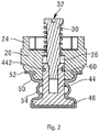
- Fig. 2 is a schematic sectional view of the assembled structure of the valve cap, valve rod, valve plug and sealing member in the valve assembly shown in Fig. 1 .
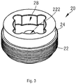
- Figs. 3 and 4 are schematic three-dimensional drawings of the valve cap and the valve body shown in Fig. 1 respectively. The valve assembly according to the present disclosure is described below in conjunction with Figs. 1 - 4 .
- the valve body 10 further comprises a valve seat part 12.
- the valve seat part 12 is located in the internal cavity, and divides the internal cavity of the valve body 10 into an inlet channel 14 and an outlet channel 16.
- a communication port 13 connecting the inlet channel 14 and the outlet channel 16 is formed in the valve seat part 12.
- the functions of the inlet channel 14 and outlet channel 16 are not defined, but may be switched as required in actual use, e.g. such that a medium flows in through the outlet channel 16 and flows out through the inlet channel 14.
- a mounting port 18 facing the communication port 13 is also formed in the valve body 10.
- the valve cap 20 is mounted at the mounting port 18.
- the valve cap 20 can be inserted into the mounting port 18, or cover the mounting port 18 in another schematic embodiment.
- the valve cap 20 is embedded in the mounting port 18 as shown in Fig. 1 .
- the valve rod 30 is movably passed through the valve cap 20.
- the valve cap 20 is provided with a through-hole 222 at a central position of a body 22 thereof.
- the valve rod 30 can pass through the through-hole 222, and at the same time is configured to be movable relative to the valve cap 20 in the axial direction of the valve rod.
- one end of the valve rod 30 can pass through the valve cap 20 and extend into the valve body, while another end is kept outside the valve body 10, so as to be driven by an actuator.
- the valve plug 40 is mounted to that end of the valve rod 30 which extends into the valve body 10, and can extend into the internal cavity of the valve body under the driving action of the valve rod 30.
- the valve plug 40 has a neck part 44 extending in the axial direction thereof, and an end part 46 extending out transversely from the neck part. In a closed position, the end part 46 of the valve plug 40 abuts the valve seat part 12, thereby blocking fluid communication at the communication port 13; in an open position, the end part 46 of the valve plug 40 is remote from the valve seat part 12, i.e. remote from the communication port 13, thereby enabling fluid communication.
- valve rod 30 and valve plug 40 may employ a threaded connection, an interference connection or another manner of connection.
- a threaded connection is employed between the valve rod 30 and valve plug 40 in the embodiment shown in Fig. 1 .
- a slot is preferably provided at an upper end part of the valve rod 30, so that a tool can be used to turn the valve rod 30 and thereby screw it tightly into the valve plug.
- the upper end part of the valve rod 30 is shown as being provided with a linear slot in Figs. 1 and 2 ; this can be easily turned with a flat-blade screwdriver.
- the upper end part of the valve rod 30 may also be provided with a cross-shaped slot or inner polygonal slot, etc., for use with different types of tools.
- the sealing member 50 is a one-piece flexible sealing member, preferably an elastic diaphragm, and more preferably a rubber diaphragm, which envelops the valve plug 40 and a side of the valve cap 20 which faces the mounting port 18, so as to isolate the valve cap 20, valve rod 30 and valve plug 40 from the internal cavity of the valve body 10 in a sealed manner.
- the sealing member 50 can not only achieve soft sealing, but can also adapt to short-travel movement of the valve plug 40.
- the sealing member 50 since the sealing member 50 is configured to envelop the valve plug 40, the sealing member 50 can achieve soft sealing between the valve plug 40 and the valve seat part 12 when the valve plug 40 abuts the valve seat part 12. Further, since the sealing member 50 also envelops the valve cap 20, the sealing member 50 can also achieve soft sealing between the valve cap 20 and the valve body 10 at the same time. Further, since the sealing member 50 envelops the valve cap 20, valve rod 30 and valve plug 40 as a whole, there is no need for separate sealing between the valve rod 30 and valve cap 20.
- the sealing member 50 is also in particular provided with a redundant part 54.
- the redundant part 54 of the sealing member 50 is piled or stowed at the position of the neck part 44 of the valve plug 40, as shown in Figs. 1 and 2 .
- the sealing member 50 extends as the valve plug 40 moves, and the redundant part 54 thereof also extends accordingly, being fully extended and lying against the neck part 44 of the valve plug when the valve plug 40 abuts the valve seat.
- the sealing member 50 having the redundant part can have a longer service life, and can adapt to scenarios in which the travel of the valve plug is longer.
- the sealing member 50 can achieve effective soft sealing throughout the course of movement of the valve plug.
- the sealing member 50 is also provided with an annular sealing part 52.
- the annular sealing part 52 is fitted round a lower edge of the valve cap 20 in a circumferential direction, and seals a gap between the valve cap 20 and the valve body 10.
- the sealing member 50 envelops those parts of the valve cap 20 and valve plug 40 which face the internal cavity, such that the valve cap 20, valve rod 30 and valve plug 40 are isolated from the internal cavity of the valve body 10 in a sealed manner.
- Soft sealing between the valve cap 20 and valve body 10, and soft sealing between the valve plug 40 and valve seat part 12, can be achieved at the same time.
- the valve cap 20 is substantially cylindrical, can be inserted into the mounting port 18 in the axial direction, and can be embedded in the mounting port 18, i.e. the body 22 of the valve cap 20 is embedded in the valve body 10.
- a peripheral surface of the valve cap 20 has an external thread
- the valve body 10 has an internal thread at the mounting port 18, and the valve cap 20 and valve body 10 employ a threaded connection.
- a thread-locking adhesive is further provided between the valve cap 20 and the thread at the mounting port 18.
- the thread-locking adhesive is an anaerobic adhesive, which can be used both for bonding and for sealing.
- the thread-locking adhesive that was originally liquid quickly cures due to being isolated from air, thereby not only bonding the valve cap 20 into the mounting port 18 of the valve body 10, but also achieving sealing at the same time, so as to inhibit and/or prevent leakage of fluid from the mounting port.
- the mounting of the sealing member 50 is dependent on the valve cap 20 and valve body 10 being pressed tightly together, with the annular sealing part 52 of the sealing member 50 being pressed tightly between the valve cap 20 and the valve body 10.
- the valve cap 20 has a keyway 28 at a side remote from the communication port 13, i.e. at a top surface in the figure, so as to use a tool to screw the valve cap 20 tightly into the mounting port 18 of the valve body 10.
- the valve cap 20 has a centrally located through-hole 222; the valve rod 30 passes through this through-hole movably, such that one end of the valve rod 30 can extend into the valve body.
- the valve cap 20 has a recess 26 at a side facing the communication port 13.
- One end of the valve rod 30 passes through the through-hole 222 in the centre of the valve cap 20 and extends into the recess 26.
- the size of the recess 26 is also adapted to accommodate an upper end of the neck part 44 of the valve plug 40.
- the neck part 44 extends into the recess 26 of the valve cap 20 movably, and is securely connected to one end of the valve rod 30.
- a sealing ring 60 is further provided between the neck part 44 of the valve plug 40 and an inner wall of the recess 26. More preferably, a circumferentially extending groove 446 may also be formed on a peripheral surface of the neck part 44, for the purpose of accommodating the sealing ring 60.
- Double sealing of the valve plug and valve cap is achieved at the same time; this includes a first layer of sealing provided by the sealing member 50, and a second layer of sealing provided by the sealing ring 60.
- the valve cap 20 also has a security ring part 24 extending out from the body 22.
- the body 22 can be completely embedded in the mounting port 18.
- the security ring part 24 has a smaller diameter than the diameter of the body 22 (internal diameter of the mounting port 18), and can extend out of the mounting port 18.
- the security ring part 24 is adapted to be connected through engagement to a mounting claw at the bottom of an actuator, thereby strengthening a firm connection between the valve assembly and the actuator.
- valve assembly since a main body of the valve cap 20 is embedded in the mounting port 18, with the security ring part 24 extending out and being connected through engagement to the actuator, the valve assembly is connected firmly to the actuator, and detachment from the valve assembly due to the actuator sustaining a lateral force will not occur.
- a return spring is fitted round the valve rod 30 at the side of the valve rod 30 that is located outside the valve body 10, with two ends of the return spring 60 abutting the valve cap 20 and an end part of the valve rod 30 respectively.
- the return spring 60 can drive the valve rod 30 to move and drive the valve plug 40 back to the open position, i.e. open the communication port 13, when the valve assembly resets.
- valve cap 20 due to the soft sealing afforded by the sealing member, cheaper materials can be used for the valve cap 20, valve rod 30 and valve plug 40, thereby reducing material costs, and further reducing the production cost of the valve assembly.
- the present disclosure further provides a control valve assembly, comprising an actuator and a valve assembly as described above.
- the actuator can be connected to the valve rod 30 and can drive the valve rod 30 to move axially relative to the valve cap 20, thereby driving the valve plug 40 to shift between the open position and the closed position.
- the actuator can also be clamped firmly on the security ring part of the valve cap by means of a mounting claw. This also increases the stability and security of mounting of the actuator.
Landscapes
- Engineering & Computer Science (AREA)
- General Engineering & Computer Science (AREA)
- Mechanical Engineering (AREA)
- Lift Valve (AREA)
Abstract
Description
- The present disclosure relates to the technical field of valves, in particular to a valve assembly and a control valve assembly having the valve assembly.
- A control valve assembly comprises a valve assembly and an actuator. The valve assembly generally employs hard sealing or soft sealing. Hard sealing has a low cost, but the quality of sealing achieved thereby could be improved. To achieve better quality of sealing, the valve assembly can also employ soft sealing. An existing valve assembly using soft sealing requires the use of sealing structures such as seal rings and sealing rings at multiple positions, resulting in a complex overall structure and a high production cost. At the same time, the valve assembly with soft sealing requires a flexible sealing member to have high durability. Thus there is a need to propose a valve assembly with a novel structure.
- An object of the present disclosure is to provide a valve assembly and a control valve assembly having the valve assembly, which adopt structurally simple soft sealing, and can effectively reduce production costs while fully guaranteeing the reliability of sealing.
- Another object of the present disclosure is to provide a valve assembly and a control valve assembly having the valve assembly, the soft sealing adopted therein having durability, improved reliability and an extended service life.
- A further object of the present disclosure is to provide a valve assembly or control valve assembly, which adopts structurally simple soft sealing, and provides double soft sealing with better sealing performance, thereby avoiding outward leakage.
- A further object of the present disclosure is to provide a valve assembly or control valve assembly, the structure thereof being adapted for firm connection to an actuator, thus simplifying the structure and increasing the firmness of connection.
- In an embodiment of the present disclosure, the valve assembly comprises: a valve body forming an internal cavity, the valve body further comprising a valve seat part, the valve seat part being located in the internal cavity and dividing the internal cavity of the valve body into an inlet channel and an outlet channel, a communication port being formed in the valve seat part, the communication port connecting the inlet channel and the outlet channel, and a mounting port also being formed in the valve body, the mounting port facing the communication port; a valve cap, adapted to be mounted at the mounting port; a valve rod, movably passed through the valve cap; a valve plug, mounted to one end of the valve rod and able to extend into the internal cavity under the driving action of the valve rod, the valve plug having a neck part extending in the axial direction thereof and an end part extending out transversely from the neck part, wherein, in a closed position, the end part abuts the valve seat part, thereby blocking fluid communication at the communication port, and in an open position, the end part is remote from the communication port, thereby enabling fluid communication; and a sealing member, being a flexible sealing member, and configured to at least envelop the valve plug and a side of the valve cap which faces the communication port, so as to isolate the valve cap, the valve rod and the valve plug from the internal cavity of the valve body in a sealed manner; wherein the sealing member has a redundant part; when the valve plug is at an open position, the redundant part is piled at the neck part of the valve plug. Preferably, the valve cap is embedded in the mounting port. By using such soft sealing and retaining redundancy, the service life of the sealing member can be extended and product reliability is improved. The sealing member is an elastic diaphragm.
- In another embodiment, the valve cap has a recess at a side facing the communication port, one end of the valve rod passing through the valve cap and extending into the recess; an upper end of the neck part of the valve plug extends into the recess of the valve cap movably, and is securely connected to the valve rod; wherein a sealing ring is provided between the neck part of the valve plug and an inner wall of the recess. Preferably, a circumferentially extending groove is formed on a peripheral surface of the neck part, for the purpose of accommodating the sealing ring. The sealing ring disposed between the valve plug and valve cap forms a double seal together with the sealing member, and this can avoid leakage. In particular, when the sealing member has broken due to fatigue, the sealing ring can still achieve a certain degree of sealing.
- In one embodiment, the valve cap has a body and a security ring part extending out from the body, wherein the body is completely embedded in the mounting port; the security ring part has a smaller diameter than the internal diameter of the mounting port and extends out of the mounting port, and the security ring part is adapted to be connected through engagement to an actuator for controlling the valve assembly. Preferably, an inner wall of the mounting port of the valve body is provided with an internal thread, and an outer wall of the body of the valve cap is provided with an external thread, wherein a thread-locking adhesive is applied between the internal thread and the external thread. The design of the security ring part enables the actuator to be engaged on the valve assembly more firmly, so that it is not likely to fall off. Preferably, the valve cap has a keyway at a side remote from the communication port, and can thereby be installed easily. More preferably, a slot is provided on an end face at that end of the valve rod which is positioned outside the valve cap, for the purpose of installing or removing the valve rod.
- In another embodiment, the control valve assembly comprises; an actuator, and a valve assembly as described above, wherein the actuator can be connected to the valve rod and can drive the valve rod to move axially relative to the valve cap, thereby driving the valve plug to shift between the open position and the closed position.
- Preferred embodiments are explained below in a clear and easily comprehensible way with reference to the accompanying drawings, to further explain the abovementioned characteristics, technical features and advantages of the valve assembly and control valve and embodiments thereof.
- The accompanying drawings below merely illustrate and explain the present disclosure schematically, without limiting the scope thereof.
-
Fig. 1 is a sectional schematic structural diagram illustrating a schematic embodiment of the valve assembly. -
Fig. 2 is a schematic sectional view of the assembled structure of the valve cap, valve rod, valve plug and sealing member in the valve assembly shown inFig. 1 . -
Fig. 3 is a three-dimensional schematic drawing of the valve cap shown inFig. 1 . -
Fig. 4 is a three-dimensional schematic drawing of the valve body shown inFig. 1 . - To enable clearer understanding of the technical features, objectives and effects of the disclosure, particular embodiments of the present disclosure are now explained with reference to the accompanying drawings, in which identical labels indicate structurally identical components or components with similar structures but identical functions.
- As used herein, "schematic" means "serving as an instance, example or illustration". No drawing or embodiment described herein as "schematic" should be interpreted as being a more preferred or more advantageous technical solution.
-
Fig. 1 is a sectional schematic structural diagram illustrating a schematic embodiment of the valve assembly. Referring toFig. 1 , the valve assembly comprises avalve body 10, avalve cap 20, avalve rod 30, a valve plug 40 and asealing member 50.Fig. 2 is a schematic sectional view of the assembled structure of the valve cap, valve rod, valve plug and sealing member in the valve assembly shown inFig. 1 .Figs. 3 and4 are schematic three-dimensional drawings of the valve cap and the valve body shown inFig. 1 respectively. The valve assembly according to the present disclosure is described below in conjunction withFigs. 1 - 4 . - An internal cavity is formed inside the
valve body 10. Thevalve body 10 further comprises avalve seat part 12. Thevalve seat part 12 is located in the internal cavity, and divides the internal cavity of thevalve body 10 into aninlet channel 14 and anoutlet channel 16. Acommunication port 13 connecting theinlet channel 14 and theoutlet channel 16 is formed in thevalve seat part 12. Here, the functions of theinlet channel 14 andoutlet channel 16 are not defined, but may be switched as required in actual use, e.g. such that a medium flows in through theoutlet channel 16 and flows out through theinlet channel 14. - As shown in
Fig. 1 , amounting port 18 facing thecommunication port 13 is also formed in thevalve body 10. Thevalve cap 20 is mounted at themounting port 18. Thevalve cap 20 can be inserted into themounting port 18, or cover themounting port 18 in another schematic embodiment. Preferably, thevalve cap 20 is embedded in themounting port 18 as shown inFig. 1 . - The
valve rod 30 is movably passed through thevalve cap 20. As shown inFigs. 1 and4 , thevalve cap 20 is provided with a through-hole 222 at a central position of abody 22 thereof. Thevalve rod 30 can pass through the through-hole 222, and at the same time is configured to be movable relative to thevalve cap 20 in the axial direction of the valve rod. Thus, one end of thevalve rod 30 can pass through thevalve cap 20 and extend into the valve body, while another end is kept outside thevalve body 10, so as to be driven by an actuator. - The valve plug 40 is mounted to that end of the
valve rod 30 which extends into thevalve body 10, and can extend into the internal cavity of the valve body under the driving action of thevalve rod 30. As shown inFigs. 1 and2 , the valve plug 40 has a neck part 44 extending in the axial direction thereof, and anend part 46 extending out transversely from the neck part. In a closed position, theend part 46 of the valve plug 40 abuts thevalve seat part 12, thereby blocking fluid communication at thecommunication port 13; in an open position, theend part 46 of the valve plug 40 is remote from thevalve seat part 12, i.e. remote from thecommunication port 13, thereby enabling fluid communication. In a schematic embodiment, thevalve rod 30 and valve plug 40 may employ a threaded connection, an interference connection or another manner of connection. For convenience of assembly and disassembly, a threaded connection is employed between thevalve rod 30 and valve plug 40 in the embodiment shown inFig. 1 . Thus, a slot is preferably provided at an upper end part of thevalve rod 30, so that a tool can be used to turn thevalve rod 30 and thereby screw it tightly into the valve plug. By way of example, the upper end part of thevalve rod 30 is shown as being provided with a linear slot inFigs. 1 and2 ; this can be easily turned with a flat-blade screwdriver. Optionally, the upper end part of thevalve rod 30 may also be provided with a cross-shaped slot or inner polygonal slot, etc., for use with different types of tools. - In
Fig. 1 , the sealingmember 50 is a one-piece flexible sealing member, preferably an elastic diaphragm, and more preferably a rubber diaphragm, which envelops the valve plug 40 and a side of thevalve cap 20 which faces the mountingport 18, so as to isolate thevalve cap 20,valve rod 30 and valve plug 40 from the internal cavity of thevalve body 10 in a sealed manner. As a complete elastic diaphragm, the sealingmember 50 can not only achieve soft sealing, but can also adapt to short-travel movement of the valve plug 40. With regard to the soft sealing, specifically, since the sealingmember 50 is configured to envelop the valve plug 40, the sealingmember 50 can achieve soft sealing between the valve plug 40 and thevalve seat part 12 when the valve plug 40 abuts thevalve seat part 12. Further, since the sealingmember 50 also envelops thevalve cap 20, the sealingmember 50 can also achieve soft sealing between thevalve cap 20 and thevalve body 10 at the same time. Further, since the sealingmember 50 envelops thevalve cap 20,valve rod 30 and valve plug 40 as a whole, there is no need for separate sealing between thevalve rod 30 andvalve cap 20. - Moreover, in
Figs. 1 and2 , the sealingmember 50 is also in particular provided with aredundant part 54. When the valve plug 40 is at the open position, i.e. when theend part 46 of the valve plug 40 is remote from thevalve seat part 12, theredundant part 54 of the sealingmember 50 is piled or stowed at the position of the neck part 44 of the valve plug 40, as shown inFigs. 1 and2 . When the valve plug 40 is at the closed position, the sealingmember 50 extends as the valve plug 40 moves, and theredundant part 54 thereof also extends accordingly, being fully extended and lying against the neck part 44 of the valve plug when the valve plug 40 abuts the valve seat. Due to theredundant part 54, the sealing member no longer relies solely on its own elastic deformation allowance to adapt to the movement travel of the valve plug; instead, theredundant part 54 makes up for the limited elastic deformation allowance. Thus, the sealingmember 50 having the redundant part can have a longer service life, and can adapt to scenarios in which the travel of the valve plug is longer. - The sealing
member 50 can achieve effective soft sealing throughout the course of movement of the valve plug. The sealingmember 50 is also provided with anannular sealing part 52. Theannular sealing part 52 is fitted round a lower edge of thevalve cap 20 in a circumferential direction, and seals a gap between thevalve cap 20 and thevalve body 10. - In the valve assembly provided in the present disclosure, the sealing
member 50 envelops those parts of thevalve cap 20 and valve plug 40 which face the internal cavity, such that thevalve cap 20,valve rod 30 and valve plug 40 are isolated from the internal cavity of thevalve body 10 in a sealed manner. Soft sealing between thevalve cap 20 andvalve body 10, and soft sealing between the valve plug 40 andvalve seat part 12, can be achieved at the same time. Moreover, there is no need for separate sealing between thevalve rod 30 andvalve cap 20, thus the structure of the valve assembly is simplified and production costs can be effectively reduced. - In a schematic embodiment, referring to
Figs. 1 ,3 and4 , thevalve cap 20 is substantially cylindrical, can be inserted into the mountingport 18 in the axial direction, and can be embedded in the mountingport 18, i.e. thebody 22 of thevalve cap 20 is embedded in thevalve body 10. In a schematic embodiment, a peripheral surface of thevalve cap 20 has an external thread, thevalve body 10 has an internal thread at the mountingport 18, and thevalve cap 20 andvalve body 10 employ a threaded connection. Preferably, a thread-locking adhesive is further provided between thevalve cap 20 and the thread at the mountingport 18. The thread-locking adhesive is an anaerobic adhesive, which can be used both for bonding and for sealing. As the valve cap and mounting port threads are screwed tightly together, the thread-locking adhesive that was originally liquid quickly cures due to being isolated from air, thereby not only bonding thevalve cap 20 into the mountingport 18 of thevalve body 10, but also achieving sealing at the same time, so as to inhibit and/or prevent leakage of fluid from the mounting port. At the same time, the mounting of the sealingmember 50 is dependent on thevalve cap 20 andvalve body 10 being pressed tightly together, with theannular sealing part 52 of the sealingmember 50 being pressed tightly between thevalve cap 20 and thevalve body 10. Thus, not only is fluid sealing between thevalve body 10 andvalve cap 20 achieved by the sealingmember 50, outward leakage is also inhibited and/or prevented by the thread-locking adhesive, thus achieving double sealing here. Preferably, as shown inFig. 3 , thevalve cap 20 has akeyway 28 at a side remote from thecommunication port 13, i.e. at a top surface in the figure, so as to use a tool to screw thevalve cap 20 tightly into the mountingport 18 of thevalve body 10. - As shown in
Figs. 1 ,2 and3 , thevalve cap 20 has a centrally located through-hole 222; thevalve rod 30 passes through this through-hole movably, such that one end of thevalve rod 30 can extend into the valve body. As shown inFigs. 1 and2 , thevalve cap 20 has arecess 26 at a side facing thecommunication port 13. One end of thevalve rod 30 passes through the through-hole 222 in the centre of thevalve cap 20 and extends into therecess 26. The size of therecess 26 is also adapted to accommodate an upper end of the neck part 44 of the valve plug 40. The neck part 44 extends into therecess 26 of thevalve cap 20 movably, and is securely connected to one end of thevalve rod 30. Preferably, a sealingring 60 is further provided between the neck part 44 of the valve plug 40 and an inner wall of therecess 26. More preferably, a circumferentially extending groove 446 may also be formed on a peripheral surface of the neck part 44, for the purpose of accommodating the sealingring 60. With such a design, the connection and fitting of thevalve rod 30 and valve plug 40 to each other can be accomplished simply in an easy operation. Double sealing of the valve plug and valve cap is achieved at the same time; this includes a first layer of sealing provided by the sealingmember 50, and a second layer of sealing provided by the sealingring 60. Thus, in the unlikely event that the sealingmember 50 breaks due to fatigue and loses its sealing ability, the sealingring 60 between the valve plug and valve cap can still work, inhibiting and/or preventing fluid leakage. - As shown in
Figs. 1 and3 , thevalve cap 20 also has asecurity ring part 24 extending out from thebody 22. Thebody 22 can be completely embedded in the mountingport 18. Thesecurity ring part 24 has a smaller diameter than the diameter of the body 22 (internal diameter of the mounting port 18), and can extend out of the mountingport 18. Thesecurity ring part 24 is adapted to be connected through engagement to a mounting claw at the bottom of an actuator, thereby strengthening a firm connection between the valve assembly and the actuator. In other words, since a main body of thevalve cap 20 is embedded in the mountingport 18, with thesecurity ring part 24 extending out and being connected through engagement to the actuator, the valve assembly is connected firmly to the actuator, and detachment from the valve assembly due to the actuator sustaining a lateral force will not occur. - In a schematic embodiment, referring to
Figs. 1 and2 , a return spring is fitted round thevalve rod 30 at the side of thevalve rod 30 that is located outside thevalve body 10, with two ends of thereturn spring 60 abutting thevalve cap 20 and an end part of thevalve rod 30 respectively. Thereturn spring 60 can drive thevalve rod 30 to move and drive the valve plug 40 back to the open position, i.e. open thecommunication port 13, when the valve assembly resets. - In a schematic embodiment, referring to
Fig. 2 , preferably, due to the soft sealing afforded by the sealing member, cheaper materials can be used for thevalve cap 20,valve rod 30 and valve plug 40, thereby reducing material costs, and further reducing the production cost of the valve assembly. - The present disclosure further provides a control valve assembly, comprising an actuator and a valve assembly as described above. The actuator can be connected to the
valve rod 30 and can drive thevalve rod 30 to move axially relative to thevalve cap 20, thereby driving the valve plug 40 to shift between the open position and the closed position. The actuator can also be clamped firmly on the security ring part of the valve cap by means of a mounting claw. This also increases the stability and security of mounting of the actuator. - It should be understood that although the description herein is based on various embodiments, it is by no means the case that each embodiment contains just one independent technical solution. Such a method of presentation is adopted herein purely for the sake of clarity. Those skilled in the art should consider the description in its entirety. The technical solutions in the various embodiments could also be suitably combined to form other embodiments capable of being understood by those skilled in the art.
- The series of detailed explanations set out above are merely particular explanations of feasible embodiments of the present disclosure, which are not intended to limit the scope of protection thereof. All equivalent embodiments or changes made without departing from the present disclosure, such as feature combinations, separations or repetitions, shall be included in the scope of protection thereof.
-
- 10 valve body
- 12 valve seat part
- 13 communication port
- 14 inlet channel
- 16 outlet channel
- 18 mounting port
- 20 valve cap
- 22 body
- 24 security ring part
- 26 recess
- 28 keyway
- 222 through-hole
- 30 valve rod
- 32 slot
- 40 valve plug
- 44 neck part
- 46 end part
- 442 circumferential groove
- 50 sealing member
- 52 annular sealing part
- 54 redundant part
- 60 sealing ring
Claims (10)
- A valve assembly, the valve assembly comprising:a valve body (10) forming an internal cavity, the valve body (10) further comprising a valve seat part (12), the valve seat part (12) being located in the internal cavity and dividing the internal cavity of the valve body (10) into an inlet channel (14) and an outlet channel (16), a communication port (13) being formed in the valve seat part (12), the communication port connecting the inlet channel (14) and the outlet channel (16), and a mounting port (18) also being formed in the valve body (10), the mounting port (18) facing the communication port (13);a valve cap (20), adapted to be mounted at the mounting port (18) ;a valve rod (30), movably passed through the valve cap (20);a valve plug (40), mounted to one end of the valve rod (30) and able to extend into the internal cavity under the driving action of the valve rod (30), the valve plug (40) having a neck part (44) extending in the axial direction thereof and an end part (46) extending out transversely from the neck part (44), wherein, in a closed position, the end part (46) abuts the valve seat part (12), thereby blocking fluid communication at the communication port (13), and in an open position, the end part (46) is remote from the communication port (13), thereby enabling fluid communication;a sealing member (50), being a flexible sealing member, and configured to at least envelop the valve plug (40) and a side of the valve cap (20) which faces the communication port (13), so as to isolate the valve cap (20), the valve rod (30) and the valve plug (40) from the internal cavity of the valve body (10) in a sealed manner;wherein the sealing member (50) has a redundant part (54); when the valve plug (40) is at an open position, the redundant part (54) is piled at the neck part (44) of the valve plug (40) .
- The valve assembly as claimed in claim 1, wherein the valve cap (20) is embedded in the mounting port (18).
- The valve assembly as claimed in claim 1, wherein the valve cap (20) has a recess (26) at a side facing the communication port (13),
one end of the valve rod (30) passing through the valve cap (20) and extending into the recess (26);
an upper end of the neck part (44) of the valve plug (40) extends into the recess (26) of the valve cap (20) movably, and is securely connected to the valve rod (30);
wherein a sealing ring (60) is provided between the neck part (44) of the valve plug (40) and an inner wall of the recess (26). - The valve assembly as claimed in claim 3, wherein a circumferentially extending groove (446) is formed on a peripheral surface of the neck part (44), for the purpose of accommodating the sealing ring (60).
- The valve assembly as claimed in claim 1, wherein the valve cap (20) has a body (22) and a security ring part (24) extending out from the body (22), wherein
the body (22) is completely embedded in the mounting port (18) ;
the security ring part (24) has a smaller diameter than the internal diameter of the mounting port (18) and extends out of the mounting port (18), and the security ring part (24) is adapted to be connected through engagement to an actuator for controlling the valve assembly. - The valve assembly as claimed in claim 5, wherein an inner wall of the mounting port (18) of the valve body (10) is provided with an internal thread, and an outer wall of the body (22) of the valve cap (20) is provided with an external thread, wherein a thread-locking adhesive is applied between the internal thread and the external thread.
- The valve assembly as claimed in claim 1, wherein the valve cap (20) has a keyway (28) at a side remote from the communication port (13).
- The valve assembly as claimed in claim 1, wherein a slot (32) is provided on an end face at that end of the valve rod (30) which is positioned outside the valve cap (20), for the purpose of installing or removing the valve rod (30).
- The valve assembly as claimed in claim 1, wherein the sealing member (50) is an elastic diaphragm.
- A control valve assembly, the control valve assembly comprising:an actuator; anda valve assembly as claimed in any one of claims 1 - 9,wherein the actuator can be connected to the valve rod (30) and can drive the valve rod (30) to move axially relative to the valve cap (20), thereby driving the valve plug (40) to shift between the open position and the closed position.
Applications Claiming Priority (1)
| Application Number | Priority Date | Filing Date | Title |
|---|---|---|---|
| CN202020681626.4U CN212429770U (en) | 2020-04-28 | 2020-04-28 | Valve assembly and control valve assembly |
Publications (3)
| Publication Number | Publication Date |
|---|---|
| EP3904742A1 true EP3904742A1 (en) | 2021-11-03 |
| EP3904742C0 EP3904742C0 (en) | 2023-08-23 |
| EP3904742B1 EP3904742B1 (en) | 2023-08-23 |
Family
ID=74294691
Family Applications (1)
| Application Number | Title | Priority Date | Filing Date |
|---|---|---|---|
| EP21170241.0A Active EP3904742B1 (en) | 2020-04-28 | 2021-04-23 | Valve assembly and control valve assembly |
Country Status (3)
| Country | Link |
|---|---|
| EP (1) | EP3904742B1 (en) |
| CN (1) | CN212429770U (en) |
| ES (1) | ES2965173T3 (en) |
Cited By (2)
| Publication number | Priority date | Publication date | Assignee | Title |
|---|---|---|---|---|
| CN115750817A (en) * | 2022-09-27 | 2023-03-07 | 济南新材料产业技术研究院 | Elastic spacer sleeve sealing high-temperature-resistant valve |
| WO2024098733A1 (en) * | 2022-11-08 | 2024-05-16 | 苏州纽威阀门股份有限公司 | Regulating valve |
Families Citing this family (1)
| Publication number | Priority date | Publication date | Assignee | Title |
|---|---|---|---|---|
| CN114962657A (en) * | 2022-06-01 | 2022-08-30 | 上海至纯精密制造有限公司 | Valve structure for prolonging service life of diaphragm of plastic diaphragm valve |
Citations (5)
| Publication number | Priority date | Publication date | Assignee | Title |
|---|---|---|---|---|
| GB2007808A (en) * | 1977-11-11 | 1979-05-23 | Sanbra Fyffe Ltd | Stop valve assembly |
| CN2209255Y (en) * | 1994-12-05 | 1995-10-04 | 成都市汇丰节能器材厂 | Non-metallic bellows combination sealing member |
| WO2002065007A1 (en) * | 2001-02-12 | 2002-08-22 | Shiyou Zhou | Valve |
| CN207514340U (en) * | 2017-11-15 | 2018-06-19 | 北京西门子西伯乐斯电子有限公司 | The valve module and control valve of control valve |
| CN208919351U (en) * | 2018-08-30 | 2019-05-31 | 西门子瑞士有限公司 | The valve member and control valve of control valve |
Family Cites Families (1)
| Publication number | Priority date | Publication date | Assignee | Title |
|---|---|---|---|---|
| US7051992B2 (en) * | 2003-08-25 | 2006-05-30 | Delphi Technologies, Inc. | Tubeless actuator with reduced secondary air gap |
-
2020
- 2020-04-28 CN CN202020681626.4U patent/CN212429770U/en active Active
-
2021
- 2021-04-23 EP EP21170241.0A patent/EP3904742B1/en active Active
- 2021-04-23 ES ES21170241T patent/ES2965173T3/en active Active
Patent Citations (5)
| Publication number | Priority date | Publication date | Assignee | Title |
|---|---|---|---|---|
| GB2007808A (en) * | 1977-11-11 | 1979-05-23 | Sanbra Fyffe Ltd | Stop valve assembly |
| CN2209255Y (en) * | 1994-12-05 | 1995-10-04 | 成都市汇丰节能器材厂 | Non-metallic bellows combination sealing member |
| WO2002065007A1 (en) * | 2001-02-12 | 2002-08-22 | Shiyou Zhou | Valve |
| CN207514340U (en) * | 2017-11-15 | 2018-06-19 | 北京西门子西伯乐斯电子有限公司 | The valve module and control valve of control valve |
| CN208919351U (en) * | 2018-08-30 | 2019-05-31 | 西门子瑞士有限公司 | The valve member and control valve of control valve |
Cited By (2)
| Publication number | Priority date | Publication date | Assignee | Title |
|---|---|---|---|---|
| CN115750817A (en) * | 2022-09-27 | 2023-03-07 | 济南新材料产业技术研究院 | Elastic spacer sleeve sealing high-temperature-resistant valve |
| WO2024098733A1 (en) * | 2022-11-08 | 2024-05-16 | 苏州纽威阀门股份有限公司 | Regulating valve |
Also Published As
| Publication number | Publication date |
|---|---|
| CN212429770U (en) | 2021-01-29 |
| EP3904742C0 (en) | 2023-08-23 |
| EP3904742B1 (en) | 2023-08-23 |
| ES2965173T3 (en) | 2024-04-11 |
Similar Documents
| Publication | Publication Date | Title |
|---|---|---|
| EP3904742B1 (en) | Valve assembly and control valve assembly | |
| US6173969B1 (en) | Sealing ring | |
| CN105190136B (en) | Rotary valve device | |
| EP3957882B1 (en) | Electronic expansion valve | |
| US10989317B2 (en) | Two-way valve | |
| US2556308A (en) | Faucet | |
| KR20230002946A (en) | stop valve | |
| CN216306751U (en) | Hydrogen-resistant steel angle type stop valve | |
| US11168808B2 (en) | Valve device for controlling media flows of any type | |
| US3104090A (en) | Diaphragm valve | |
| JP2018507997A (en) | Ball valve with rotary decoupling device | |
| US9046098B2 (en) | Face sealing annular valve for a fluid-working machine | |
| JP4744319B2 (en) | Diaphragm valve | |
| CN115111385A (en) | Automatic compensation butterfly valve disk seat seal structure | |
| WO2025140714A1 (en) | Valve device and fluid control assembly | |
| CN208871085U (en) | A kind of solenoid valve | |
| EP4450854A1 (en) | Valve assembly, stop valve and refrigeration system having same | |
| CN218780781U (en) | Valve needle assembly and electronic expansion valve | |
| KR20210013163A (en) | Manifold | |
| CN114087372B (en) | Stop valve | |
| US3352532A (en) | Corrosion resistant valve | |
| JP4578158B2 (en) | Clutch piston for fluid transmission | |
| CN214789110U (en) | Low cage valve body that leaks | |
| KR200323348Y1 (en) | Disk structure of gate valve | |
| CN218494254U (en) | Diaphragm valve convenient to processing installation |
Legal Events
| Date | Code | Title | Description |
|---|---|---|---|
| PUAI | Public reference made under article 153(3) epc to a published international application that has entered the european phase |
Free format text: ORIGINAL CODE: 0009012 |
|
| STAA | Information on the status of an ep patent application or granted ep patent |
Free format text: STATUS: THE APPLICATION HAS BEEN PUBLISHED |
|
| STAA | Information on the status of an ep patent application or granted ep patent |
Free format text: STATUS: REQUEST FOR EXAMINATION WAS MADE |
|
| AK | Designated contracting states |
Kind code of ref document: A1 Designated state(s): AL AT BE BG CH CY CZ DE DK EE ES FI FR GB GR HR HU IE IS IT LI LT LU LV MC MK MT NL NO PL PT RO RS SE SI SK SM TR |
|
| B565 | Issuance of search results under rule 164(2) epc |
Effective date: 20210924 |
|
| 17P | Request for examination filed |
Effective date: 20211005 |
|
| RBV | Designated contracting states (corrected) |
Designated state(s): AL AT BE BG CH CY CZ DE DK EE ES FI FR GB GR HR HU IE IS IT LI LT LU LV MC MK MT NL NO PL PT RO RS SE SI SK SM TR |
|
| STAA | Information on the status of an ep patent application or granted ep patent |
Free format text: STATUS: EXAMINATION IS IN PROGRESS |
|
| 17Q | First examination report despatched |
Effective date: 20220711 |
|
| REG | Reference to a national code |
Ref country code: DE Ref legal event code: R079 Free format text: PREVIOUS MAIN CLASS: F16K0041100000 Ipc: F16K0011160000 Ref document number: 602021004431 Country of ref document: DE |
|
| RIC1 | Information provided on ipc code assigned before grant |
Ipc: F16K 31/53 20060101ALI20230324BHEP Ipc: F16K 11/16 20060101AFI20230324BHEP |
|
| GRAP | Despatch of communication of intention to grant a patent |
Free format text: ORIGINAL CODE: EPIDOSNIGR1 |
|
| STAA | Information on the status of an ep patent application or granted ep patent |
Free format text: STATUS: GRANT OF PATENT IS INTENDED |
|
| INTG | Intention to grant announced |
Effective date: 20230509 |
|
| GRAS | Grant fee paid |
Free format text: ORIGINAL CODE: EPIDOSNIGR3 |
|
| GRAA | (expected) grant |
Free format text: ORIGINAL CODE: 0009210 |
|
| STAA | Information on the status of an ep patent application or granted ep patent |
Free format text: STATUS: THE PATENT HAS BEEN GRANTED |
|
| AK | Designated contracting states |
Kind code of ref document: B1 Designated state(s): AL AT BE BG CH CY CZ DE DK EE ES FI FR GB GR HR HU IE IS IT LI LT LU LV MC MK MT NL NO PL PT RO RS SE SI SK SM TR |
|
| REG | Reference to a national code |
Ref country code: GB Ref legal event code: FG4D |
|
| REG | Reference to a national code |
Ref country code: CH Ref legal event code: EP |
|
| REG | Reference to a national code |
Ref country code: IE Ref legal event code: FG4D |
|
| REG | Reference to a national code |
Ref country code: DE Ref legal event code: R096 Ref document number: 602021004431 Country of ref document: DE |
|
| U01 | Request for unitary effect filed |
Effective date: 20230825 |
|
| U07 | Unitary effect registered |
Designated state(s): AT BE BG DE DK EE FI FR IT LT LU LV MT NL PT SE SI Effective date: 20230831 |
|
| PG25 | Lapsed in a contracting state [announced via postgrant information from national office to epo] |
Ref country code: GR Free format text: LAPSE BECAUSE OF FAILURE TO SUBMIT A TRANSLATION OF THE DESCRIPTION OR TO PAY THE FEE WITHIN THE PRESCRIBED TIME-LIMIT Effective date: 20231124 |
|
| PG25 | Lapsed in a contracting state [announced via postgrant information from national office to epo] |
Ref country code: IS Free format text: LAPSE BECAUSE OF FAILURE TO SUBMIT A TRANSLATION OF THE DESCRIPTION OR TO PAY THE FEE WITHIN THE PRESCRIBED TIME-LIMIT Effective date: 20231223 |
|
| PG25 | Lapsed in a contracting state [announced via postgrant information from national office to epo] |
Ref country code: RS Free format text: LAPSE BECAUSE OF FAILURE TO SUBMIT A TRANSLATION OF THE DESCRIPTION OR TO PAY THE FEE WITHIN THE PRESCRIBED TIME-LIMIT Effective date: 20230823 Ref country code: NO Free format text: LAPSE BECAUSE OF FAILURE TO SUBMIT A TRANSLATION OF THE DESCRIPTION OR TO PAY THE FEE WITHIN THE PRESCRIBED TIME-LIMIT Effective date: 20231123 Ref country code: IS Free format text: LAPSE BECAUSE OF FAILURE TO SUBMIT A TRANSLATION OF THE DESCRIPTION OR TO PAY THE FEE WITHIN THE PRESCRIBED TIME-LIMIT Effective date: 20231223 Ref country code: HR Free format text: LAPSE BECAUSE OF FAILURE TO SUBMIT A TRANSLATION OF THE DESCRIPTION OR TO PAY THE FEE WITHIN THE PRESCRIBED TIME-LIMIT Effective date: 20230823 Ref country code: GR Free format text: LAPSE BECAUSE OF FAILURE TO SUBMIT A TRANSLATION OF THE DESCRIPTION OR TO PAY THE FEE WITHIN THE PRESCRIBED TIME-LIMIT Effective date: 20231124 |
|
| PG25 | Lapsed in a contracting state [announced via postgrant information from national office to epo] |
Ref country code: PL Free format text: LAPSE BECAUSE OF FAILURE TO SUBMIT A TRANSLATION OF THE DESCRIPTION OR TO PAY THE FEE WITHIN THE PRESCRIBED TIME-LIMIT Effective date: 20230823 |
|
| REG | Reference to a national code |
Ref country code: ES Ref legal event code: FG2A Ref document number: 2965173 Country of ref document: ES Kind code of ref document: T3 Effective date: 20240411 |
|
| PG25 | Lapsed in a contracting state [announced via postgrant information from national office to epo] |
Ref country code: SM Free format text: LAPSE BECAUSE OF FAILURE TO SUBMIT A TRANSLATION OF THE DESCRIPTION OR TO PAY THE FEE WITHIN THE PRESCRIBED TIME-LIMIT Effective date: 20230823 Ref country code: RO Free format text: LAPSE BECAUSE OF FAILURE TO SUBMIT A TRANSLATION OF THE DESCRIPTION OR TO PAY THE FEE WITHIN THE PRESCRIBED TIME-LIMIT Effective date: 20230823 Ref country code: CZ Free format text: LAPSE BECAUSE OF FAILURE TO SUBMIT A TRANSLATION OF THE DESCRIPTION OR TO PAY THE FEE WITHIN THE PRESCRIBED TIME-LIMIT Effective date: 20230823 Ref country code: SK Free format text: LAPSE BECAUSE OF FAILURE TO SUBMIT A TRANSLATION OF THE DESCRIPTION OR TO PAY THE FEE WITHIN THE PRESCRIBED TIME-LIMIT Effective date: 20230823 |
|
| U20 | Renewal fee for the european patent with unitary effect paid |
Year of fee payment: 4 Effective date: 20240418 |
|
| REG | Reference to a national code |
Ref country code: DE Ref legal event code: R097 Ref document number: 602021004431 Country of ref document: DE |
|
| PLBE | No opposition filed within time limit |
Free format text: ORIGINAL CODE: 0009261 |
|
| STAA | Information on the status of an ep patent application or granted ep patent |
Free format text: STATUS: NO OPPOSITION FILED WITHIN TIME LIMIT |
|
| 26N | No opposition filed |
Effective date: 20240524 |
|
| PGFP | Annual fee paid to national office [announced via postgrant information from national office to epo] |
Ref country code: ES Payment date: 20240722 Year of fee payment: 4 |
|
| PG25 | Lapsed in a contracting state [announced via postgrant information from national office to epo] |
Ref country code: MC Free format text: LAPSE BECAUSE OF FAILURE TO SUBMIT A TRANSLATION OF THE DESCRIPTION OR TO PAY THE FEE WITHIN THE PRESCRIBED TIME-LIMIT Effective date: 20230823 |
|
| PG25 | Lapsed in a contracting state [announced via postgrant information from national office to epo] |
Ref country code: MC Free format text: LAPSE BECAUSE OF FAILURE TO SUBMIT A TRANSLATION OF THE DESCRIPTION OR TO PAY THE FEE WITHIN THE PRESCRIBED TIME-LIMIT Effective date: 20230823 |
|
| REG | Reference to a national code |
Ref country code: CH Ref legal event code: PL |
|
| PG25 | Lapsed in a contracting state [announced via postgrant information from national office to epo] |
Ref country code: CH Free format text: LAPSE BECAUSE OF NON-PAYMENT OF DUE FEES Effective date: 20240430 |
|
| PG25 | Lapsed in a contracting state [announced via postgrant information from national office to epo] |
Ref country code: IE Free format text: LAPSE BECAUSE OF NON-PAYMENT OF DUE FEES Effective date: 20240423 |
|
| PG25 | Lapsed in a contracting state [announced via postgrant information from national office to epo] |
Ref country code: CY Free format text: LAPSE BECAUSE OF FAILURE TO SUBMIT A TRANSLATION OF THE DESCRIPTION OR TO PAY THE FEE WITHIN THE PRESCRIBED TIME-LIMIT; INVALID AB INITIO Effective date: 20210423 |
|
| PG25 | Lapsed in a contracting state [announced via postgrant information from national office to epo] |
Ref country code: HU Free format text: LAPSE BECAUSE OF FAILURE TO SUBMIT A TRANSLATION OF THE DESCRIPTION OR TO PAY THE FEE WITHIN THE PRESCRIBED TIME-LIMIT; INVALID AB INITIO Effective date: 20210423 |
|
| U90 | Renewal fees not paid: noting of loss of rights |
Free format text: RENEWAL FEE NOT PAID FOR YEAR 05 Effective date: 20251117 |
|
| GBPC | Gb: european patent ceased through non-payment of renewal fee |
Effective date: 20250423 |
|
| PG25 | Lapsed in a contracting state [announced via postgrant information from national office to epo] |
Ref country code: GB Free format text: LAPSE BECAUSE OF NON-PAYMENT OF DUE FEES Effective date: 20250423 |
|
| U93 | Unitary patent lapsed |
Free format text: RENEWAL FEE NOT PAID Effective date: 20250430 |