EP3904276A1 - Dispensing head - Google Patents
Dispensing head Download PDFInfo
- Publication number
- EP3904276A1 EP3904276A1 EP19904681.4A EP19904681A EP3904276A1 EP 3904276 A1 EP3904276 A1 EP 3904276A1 EP 19904681 A EP19904681 A EP 19904681A EP 3904276 A1 EP3904276 A1 EP 3904276A1
- Authority
- EP
- European Patent Office
- Prior art keywords
- plunger
- drink
- seal means
- valve
- fluid inlet
- Prior art date
- Legal status (The legal status is an assumption and is not a legal conclusion. Google has not performed a legal analysis and makes no representation as to the accuracy of the status listed.)
- Withdrawn
Links
- 239000012530 fluid Substances 0.000 claims description 105
- 238000005406 washing Methods 0.000 description 94
- 239000007789 gas Substances 0.000 description 50
- 235000013405 beer Nutrition 0.000 description 8
- 238000004891 communication Methods 0.000 description 7
- CURLTUGMZLYLDI-UHFFFAOYSA-N Carbon dioxide Chemical compound O=C=O CURLTUGMZLYLDI-UHFFFAOYSA-N 0.000 description 6
- XLYOFNOQVPJJNP-UHFFFAOYSA-N water Substances O XLYOFNOQVPJJNP-UHFFFAOYSA-N 0.000 description 5
- 239000002184 metal Substances 0.000 description 4
- 238000012856 packing Methods 0.000 description 4
- 239000004033 plastic Substances 0.000 description 4
- 229920003023 plastic Polymers 0.000 description 4
- 229910002092 carbon dioxide Inorganic materials 0.000 description 3
- 239000001569 carbon dioxide Substances 0.000 description 3
- 239000000498 cooling water Substances 0.000 description 3
- GXCLVBGFBYZDAG-UHFFFAOYSA-N N-[2-(1H-indol-3-yl)ethyl]-N-methylprop-2-en-1-amine Chemical compound CN(CCC1=CNC2=C1C=CC=C2)CC=C GXCLVBGFBYZDAG-UHFFFAOYSA-N 0.000 description 2
- 239000002033 PVDF binder Substances 0.000 description 2
- 239000004698 Polyethylene Substances 0.000 description 2
- CDBYLPFSWZWCQE-UHFFFAOYSA-L Sodium Carbonate Chemical compound [Na+].[Na+].[O-]C([O-])=O CDBYLPFSWZWCQE-UHFFFAOYSA-L 0.000 description 2
- 235000013334 alcoholic beverage Nutrition 0.000 description 2
- 235000014171 carbonated beverage Nutrition 0.000 description 2
- 229920000840 ethylene tetrafluoroethylene copolymer Polymers 0.000 description 2
- 239000011521 glass Substances 0.000 description 2
- 239000000463 material Substances 0.000 description 2
- 230000007246 mechanism Effects 0.000 description 2
- -1 polyethylene Polymers 0.000 description 2
- 229920000573 polyethylene Polymers 0.000 description 2
- 229920001343 polytetrafluoroethylene Polymers 0.000 description 2
- 239000004810 polytetrafluoroethylene Substances 0.000 description 2
- 229920002981 polyvinylidene fluoride Polymers 0.000 description 2
- 230000002265 prevention Effects 0.000 description 2
- IJGRMHOSHXDMSA-UHFFFAOYSA-N Atomic nitrogen Chemical compound N#N IJGRMHOSHXDMSA-UHFFFAOYSA-N 0.000 description 1
- 230000001476 alcoholic effect Effects 0.000 description 1
- 230000008859 change Effects 0.000 description 1
- 238000001816 cooling Methods 0.000 description 1
- 230000008878 coupling Effects 0.000 description 1
- 238000010168 coupling process Methods 0.000 description 1
- 238000005859 coupling reaction Methods 0.000 description 1
- 230000007547 defect Effects 0.000 description 1
- 230000008021 deposition Effects 0.000 description 1
- 229910001873 dinitrogen Inorganic materials 0.000 description 1
- 230000000694 effects Effects 0.000 description 1
- 235000011389 fruit/vegetable juice Nutrition 0.000 description 1
- 230000006870 function Effects 0.000 description 1
- 239000004973 liquid crystal related substance Substances 0.000 description 1
- 230000007257 malfunction Effects 0.000 description 1
- 238000004519 manufacturing process Methods 0.000 description 1
- 238000000034 method Methods 0.000 description 1
- 238000012986 modification Methods 0.000 description 1
- 230000004048 modification Effects 0.000 description 1
- 230000008569 process Effects 0.000 description 1
- 238000012545 processing Methods 0.000 description 1
- 238000007789 sealing Methods 0.000 description 1
- 235000015096 spirit Nutrition 0.000 description 1
- 238000006467 substitution reaction Methods 0.000 description 1
- 235000015041 whisky Nutrition 0.000 description 1
Images


Classifications
-
- B—PERFORMING OPERATIONS; TRANSPORTING
- B67—OPENING, CLOSING OR CLEANING BOTTLES, JARS OR SIMILAR CONTAINERS; LIQUID HANDLING
- B67D—DISPENSING, DELIVERING OR TRANSFERRING LIQUIDS, NOT OTHERWISE PROVIDED FOR
- B67D1/00—Apparatus or devices for dispensing beverages on draught
- B67D1/04—Apparatus utilising compressed air or other gas acting directly or indirectly on beverages in storage containers
- B67D1/0406—Apparatus utilising compressed air or other gas acting directly or indirectly on beverages in storage containers with means for carbonating the beverage, or for maintaining its carbonation
-
- B—PERFORMING OPERATIONS; TRANSPORTING
- B67—OPENING, CLOSING OR CLEANING BOTTLES, JARS OR SIMILAR CONTAINERS; LIQUID HANDLING
- B67D—DISPENSING, DELIVERING OR TRANSFERRING LIQUIDS, NOT OTHERWISE PROVIDED FOR
- B67D1/00—Apparatus or devices for dispensing beverages on draught
- B67D1/07—Cleaning beverage-dispensing apparatus
-
- B—PERFORMING OPERATIONS; TRANSPORTING
- B67—OPENING, CLOSING OR CLEANING BOTTLES, JARS OR SIMILAR CONTAINERS; LIQUID HANDLING
- B67D—DISPENSING, DELIVERING OR TRANSFERRING LIQUIDS, NOT OTHERWISE PROVIDED FOR
- B67D1/00—Apparatus or devices for dispensing beverages on draught
- B67D1/0042—Details of specific parts of the dispensers
-
- B—PERFORMING OPERATIONS; TRANSPORTING
- B67—OPENING, CLOSING OR CLEANING BOTTLES, JARS OR SIMILAR CONTAINERS; LIQUID HANDLING
- B67D—DISPENSING, DELIVERING OR TRANSFERRING LIQUIDS, NOT OTHERWISE PROVIDED FOR
- B67D1/00—Apparatus or devices for dispensing beverages on draught
- B67D1/04—Apparatus utilising compressed air or other gas acting directly or indirectly on beverages in storage containers
-
- B—PERFORMING OPERATIONS; TRANSPORTING
- B67—OPENING, CLOSING OR CLEANING BOTTLES, JARS OR SIMILAR CONTAINERS; LIQUID HANDLING
- B67D—DISPENSING, DELIVERING OR TRANSFERRING LIQUIDS, NOT OTHERWISE PROVIDED FOR
- B67D1/00—Apparatus or devices for dispensing beverages on draught
- B67D1/08—Details
- B67D1/0829—Keg connection means
- B67D1/0831—Keg connection means combined with valves
- B67D1/0832—Keg connection means combined with valves with two valves disposed concentrically
- B67D1/0834—Keg connection means combined with valves with two valves disposed concentrically and having means for admitting a cleaning fluid
-
- B—PERFORMING OPERATIONS; TRANSPORTING
- B67—OPENING, CLOSING OR CLEANING BOTTLES, JARS OR SIMILAR CONTAINERS; LIQUID HANDLING
- B67D—DISPENSING, DELIVERING OR TRANSFERRING LIQUIDS, NOT OTHERWISE PROVIDED FOR
- B67D1/00—Apparatus or devices for dispensing beverages on draught
- B67D1/08—Details
- B67D1/0857—Cooling arrangements
- B67D1/0858—Cooling arrangements using compression systems
- B67D1/0861—Cooling arrangements using compression systems the evaporator acting through an intermediate heat transfer means
- B67D1/0864—Cooling arrangements using compression systems the evaporator acting through an intermediate heat transfer means in the form of a cooling bath
-
- B—PERFORMING OPERATIONS; TRANSPORTING
- B67—OPENING, CLOSING OR CLEANING BOTTLES, JARS OR SIMILAR CONTAINERS; LIQUID HANDLING
- B67D—DISPENSING, DELIVERING OR TRANSFERRING LIQUIDS, NOT OTHERWISE PROVIDED FOR
- B67D1/00—Apparatus or devices for dispensing beverages on draught
- B67D1/08—Details
- B67D1/0888—Means comprising electronic circuitry (e.g. control panels, switching or controlling means)
-
- B—PERFORMING OPERATIONS; TRANSPORTING
- B67—OPENING, CLOSING OR CLEANING BOTTLES, JARS OR SIMILAR CONTAINERS; LIQUID HANDLING
- B67D—DISPENSING, DELIVERING OR TRANSFERRING LIQUIDS, NOT OTHERWISE PROVIDED FOR
- B67D3/00—Apparatus or devices for controlling flow of liquids under gravity from storage containers for dispensing purposes
- B67D3/04—Liquid-dispensing taps or cocks adapted to seal and open tapping holes of casks, e.g. for beer
Definitions
- the present application relates to a dispensing head.
- Patent Literature 1 discloses a drink dispenser provided with a drink container containing a drink, a dispensing head attached to the drink container, and a dispenser body connected to the dispensing head.
- the dispensing head has an inlet and outlet.
- the dispensing head has a first communication path connecting the inlet and outlet through the inside of the drink container and a second communication path connecting the inlet and outlet without going through the inside of the drink container.
- the inlet is connected through a fluid selecting means to a carbon dioxide gas tank and a washing solution supplying means and is configured so that by switching the fluid selecting means, one of carbon dioxide and a washing solution is received.
- the dispensing head has an operating lever for switching between the first communication path and the second communication path and a tilt sensor for outputting a signal to the outside in accordance with a tilted state of the operating lever.
- the tilt sensor for example, is configured so as to output a signal to the outside when the second communication path is selected by the operating lever.
- the fluid selecting means is configured to supply the washing solution to the inlet only if a signal is output from the tilt sensor (that is, only if the inlet and discharge outlet are connected without going through the inside of the drink container). If the inlet and discharge outlet are connected through the inside of the drink container by such a configuration, the mistaken supply of the washing solution to the inside of the drink container is prevented.
- the dispensing head In the drink dispenser of PTL 1, to prevent the washing solution from mistakenly being supplied to the inside of the drink container, the dispensing head has a tilt sensor attached to it.
- control of the drink dispenser may become complicated. Further, the manufacturing costs increase. Further, the dispensing head is sometimes placed in an environment where it may be contaminated by the drink or splashed with water. Electronic components like a tilt sensor may malfunction due to deposition of drink or water.
- the present invention has as its object to provide a dispensing head which solves the above such defect while is able to prevent a washing solution from mistakenly being supplied to the inside of the drink container.
- One embodiment of the present disclosure is a dispensing head attached to a spear valve of a drink container, the dispensing head comprising a case to be fixed to the spear valve, which case has a first through hole fluidly communicating with an inside of the spear valve, and a plunger sliding inside the first through hole of the case, which plunger has a second through hole fluidly communicating with an inside of the spear valve, the case comprising a first fluid inlet fluidly communicating with the first through hole, a first seal means arranged in the first through hole at a downstream side from the first fluid inlet and slidingly contacting the outer circumferential surface of the plunger, a second fluid inlet fluidly communicating with the first through hole at a downstream side from the first seal means, and a second seal means arranged in the first through hole at a downstream side from the second fluid inlet and slidingly contacting the outer circumferential surface of the plunger, the plunger comprising a first groove for forming a clearance between the outer circumferential surface of the plunger and the first seal means, a
- the case has two fluid inlets (first fluid inlet and second fluid inlet). Further, the dispensing head has three connection states (first, second, and third connection states). According to the configuration of a dispensing head according to one embodiment of the present disclosure, the first fluid inlet is cut off from the inside of the drink container and the second through hole of the plunger in the first connection state and the third connection state among the three connection states. Further, the first fluid inlet is fluidly communicated with the second through hole of the plunger even in the second connection state, but is cut off from the inside of the drink container. That is, the first fluid inlet is cut off from the inside of the drink container in all of the three connection states.
- the washing solution can be mechanically prevented from flowing to the inside of the drink container. Therefore, it is possible to reliably prevent the washing solution from being mistakenly supplied to the inside of the drink container.
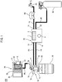
- FIG. 1 is a schematic view of the configuration of a drink supply system including the dispensing head according to the present embodiment.
- a drink supply system 100 comprises a washing apparatus 10, drink container 20, drink server 30, washing solution supply source 40, and gas supply source 50.
- the drink container 20 has a spear valve 60.
- a dispensing head 70 is attached to the spear valve 60 (particulars explained later).
- the washing apparatus 10 is used for washing a drink passage from the dispensing head 70 to the drink server 30.
- the washing apparatus 10 for example, has a drink supply mode for supplying a drink and a washing mode for washing the drink passage.
- the washing apparatus 10 has a housing 1. Inside the housing 1, a washing solution inlet 11, gas inlet 12, washing solution outlet 13, and gas outlet 14 are provided.
- the washing solution inlet 11 and gas inlet 12 are respectively connected through pipes P1 and P2 to the washing solution supply source 40 and gas supply source 50.
- the washing solution outlet 13 and gas outlet 14 are respectively connected through pipes P3 and P4 to the first fluid inlet 71 and the second fluid inlet 72 of the dispensing head 70.
- the washing solution inlet 11, gas inlet 12, washing solution outlet 13, and gas outlet 14 may also be provided with couplings for connecting with the pipes P1 to P4.
- the washing apparatus 10 further has a display part 3 and a button 4.
- the display part 3 may, for example, be a liquid crystal display.
- the display part 3 can, for example, show various information received from a not shown processor (for example, errors, washing time, and/or selected modes etc.)
- the button 4 can, for example, be a mechanical type button.
- the button 4, for example, can be used to start the washing mode.
- the washing apparatus 10, for example, may further have a not shown processor, memory, real time clock, or other component element.
- the processor which may be a CPU (central processing unit) or MPU (microprocessor unit), may be electrically connected to the display part 3 and button 4 and the valve V and sensor SE shown below (see FIG. 2 ). It may communicate with component elements in one direction or both directions.
- the operations performed at the processor may be realized by programs stored in, for example, the memory.
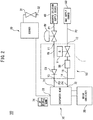
- FIG. 2 is a schematic view of the configuration of a drink supply system showing the internal configuration of a washing apparatus.
- a washing apparatus 10 has a first passage 15 and a second passage 16 inside of a housing 1.
- the first passage 15 connects the washing solution inlet 11 and washing solution outlet 13.
- the second passage 16 connects the gas inlet 12 and gas outlet 14.
- the first passage 15 and the second passage 16 can, for example, be formed by pipes of various materials able to withstand the pressure of the gas and washing solution (for example, polyethylene (PE), polyvinylidene fluoride (PVDF), ethylene tetrafluoroethylene copolymer (ETFE), and polytetrafluoroethylene (PTFE)).
- PE polyethylene
- PVDF polyvinylidene fluoride
- ETFE ethylene tetrafluoroethylene copolymer
- PTFE polytetrafluoroethylene
- the first passage 15 is provided with a check valve CV.
- the second passage 16 is provided with a valve V and a sensor SE.
- the valve V for example, can be a pilot type solenoid valve.
- the valve V for example, can be normally open (NO).
- the sensor SE can be used for detecting the flow of gas.
- it may be a pressure difference meter or a flow sensor.
- the sensor SE can measure the time of flow of gas in the gas substitution process in the piping after completion of washing and have the function of confirming whether the inside of the piping has finished being replaced in gas.
- the drink container 20 can be a beer keg.
- the drink container 20 can store various drinks (for example, beer, alcoholic carbonated drinks other than beer (for example, low malt beer, beer flavored alcoholic drinks made from materials other than malt and in which other alcoholic drinks are mixed (so-called "third sector beer"), spirits with soda, or whiskey with soda), or nonalcoholic carbonated drinks (nonalcohol beer or carbonated juice) etc.)
- various drinks for example, beer, alcoholic carbonated drinks other than beer (for example, low malt beer, beer flavored alcoholic drinks made from materials other than malt and in which other alcoholic drinks are mixed (so-called "third sector beer"), spirits with soda, or whiskey with soda), or nonalcoholic carbonated drinks (nonalcohol beer or carbonated juice) etc.)
- the drink server 30 can, for example, have a stopcock type valve (below, also able to be referred to as a "stopcock valve") 31. Below the discharge outlet 32 of the stopcock valve 31, a glass or other container (not shown) is disposed at the time of supplying a drink. At the time of washing and at the time of replacing a drink container 20, a bucket or other relatively large container B is disposed.
- the drink server 30 has a cooling water tank 33.
- the cooling water tank 33 holds a coil shaped pipe 34 connected to the stopcock valve 31.
- the cooling water tank 33 is cooled by a cooling apparatus 35. By such a configuration, drink passing through the coil-shaped pipe 34 is cooled.
- a pipe P5 connected to a fluid outlet 73 of the dispensing head 70 is connected.
- the washing solution supply source 40 supplies the washing solution for washing the drink passage.
- the washing solution for example, can be water.
- the washing solution supply source 40 can, for example, be a water faucet. If the washing solution supply source 40 is a water faucet, the pipe P1 connected to the washing solution supply source 40 may be provided with a reducing valve.
- the gas supply source 50 can, for example, be a gas tank.
- the gas supply source 50 can, for example, supply carbon dioxide gas, nitrogen gas, pressurized air, or other gas.
- FIG. 3 , FIG. 4 , and FIG. 5 respectively are schematic views of the configuration of a dispensing head in the first, second, and third connection states.
- the spear valve 60 is configured to be attached to a not shown opening of a drink container 20 (not shown in FIG. 3 to FIG. 5 ).
- the spear valve 60 has a valve case 61, a gas-use valve 62, and a drink-use valve 63.
- the valve case 61 has a substantially cylindrical shape and holds a gas-use valve 62 and drink-use valve 63.
- the valve case 61 includes an opening 61a to which a case 75 of the dispensing head 70 is fastened.
- a not shown male screw is formed at the outer circumferential surface 61b of the valve case 61. This male screw engages with a female screw formed at an opening of the drink container 20. Using this, the spear valve 60 is attached to the body of the drink container 20.
- the gas-use valve 62 is used for opening and closing a gas passage.
- the gas-use valve 62 has a substantially cylindrical shape.
- the clearance between the outer circumferential surface 62a of the gas-use valve 62 and the inner circumferential surface 61c of the valve case 61 defines part of the gas passage GP.
- the gas passage GP continues from the inside of the dispensing head 70 to the inside of the drink container 20 (in FIG. 3 , below the spear valve 60).
- the gas-use valve 62 has an outward facing flange 62b for engaging with a lower side edge part of the opening 61a of the valve case 61.
- a seal means S1 is attached at the flange 62b.
- the seal means S1 contacts the lower side edge part of the opening 61a.
- the flange 62b is biased by the spring SP1 toward the opening 61a. Due to this, the gas-use valve 62 is configured to open and close the gas passage GP.
- the gas-use valve 62 has an inward facing flange 62d at the inside of the flange 62b.
- the flange 62d has a ring shape and has a through hole.
- a seal means S2 is attached at the flange 62d.
- the drink-use valve 63 is used for opening and closing the drink passage.
- the drink-use valve 63 has a substantially cylindrical shape.
- the clearance between the outer circumferential surface 63a of the drink-use valve 63 and the inner circumferential surface 62c of the gas-use valve 62 defines part of the drink passage DP.
- the drink passage DP continues from the inside of the drink container 20 to the inside of the dispensing head 70.
- the drink-use valve 63 has an outward facing flange 63b for engaging with the inward facing flange 62d of the gas-use valve 62.
- the seal means S2 attached to the flange 62d contacts the flange 63b of the drink-use valve 63.
- the flange 63b is biased by the spring SP2 toward the flange 62d. Due to this, the drink-use valve 63 is configured to open and close the drink passage DP.
- the seal means S1 and S2 for example, can be O-rings or other plastic or metal ring-shaped gaskets or packings.
- the dispensing head 70 has the case 75 and the plunger 76. Further, referring to FIG. 1 , the dispensing head 70 has an operating lever 74.
- the case 75 is fixed to the spear valve 60.
- the case 75 has a substantially cylindrical shape and has an outward facing flange 75a at its bottom end part.
- the flange 75a engages with a groove provided at the opening 61a of the valve case 61.
- a seal means S3 is attached at the flange 75a for sealing the clearance between the case 75 and the valve case 61.
- the seal means S3, for example, can be an O-ring or other plastic or metal ring-shaped gasket or packing.
- a first through hole 77 is defined at the inside circumferential surface of the case 75.
- the first through hole 77 is fluidly communicated with the inside of the spear valve 60.
- a fluid passage is formed at the clearance of the case 75 and the plunger 76.
- the case 75 has a first fluid inlet 71 and a second fluid inlet 72.
- the first fluid inlet 71 and the second fluid inlet 72 are fluidly communicated with the first through hole 77.
- the second fluid inlet 72 is provided closer to the first fluid inlet 71 than the spear valve 60.
- the first fluid inlet 71 is supplied with the washing solution through the pipe P3 (not shown in FIG. 3 ) while the second fluid inlet 72 is supplied with the gas though the pipe P4 (not shown in FIG. 3 ).
- the case 75 has seal means S4 to S6 inside the first through hole 77.
- the seal means S4 to S6 are configured to slidingly contact the outer circumferential surface of the plunger 76.
- the case 75 has the seal means S4, first fluid inlet 71, seal means S5, second fluid inlet 72, and seal means S6 in that order along the direction of flow of the fluid (washing solution and/or gas) inside of the first through hole 77 (inside clearance between the case 75 and the plunger 76).
- the seal means S4 is arranged closer to the first fluid inlet 71 than the end part of the case 75 (top end part) at the opposite side to the spear valve 60.
- the seal means S4 is arranged so as to constantly slidingly contact the outer circumferential surface of the plunger 76. Due to the seal means S4, at the end part at the opposite side from the spear valve 60, leakage of fluid from the clearance between the case 75 and the plunger 76 is prevented. Due to this, the flow of fluid inside the first through hole 77 heads toward the spear valve.
- the seal means (first seal means) S5 is arranged between the first fluid inlet 71 and the second fluid inlet 72.
- the seal means (second seal means) S6 is provided closer to the second fluid inlet 72 than the spear valve 60.
- the above seal means S4 to S6, for example, can be O-rings or other plastic or metal ring-shaped gaskets or packings.
- the plunger 76 has a substantially cylindrical shape smaller than the case 75 and is inserted inside of the case 75.
- the plunger 76 is configured so as to slide inside of the first through hole 77 of the case 75.
- the plunger 76 can slide inside of the first through hole 77 among the corresponding three positions (first, second, and third positions). Due to this, the dispensing head 70 has three connection states (first, second, and third connection states) (details explained later).
- a second through hole 78 is defined at the inside circumferential surface of the plunger 76.
- the second through hole 78 fluidly communicates with the inside of the spear valve 60.
- a backflow prevention mechanism 78a is provided inside of the second through hole 78 for preventing flow of fluid in the direction from the fluid outlet 73 toward the spear valve 60.
- the backflow prevention mechanism 78a can include a ball, a step part formed inside the second through hole 78 and configured to be contacted by the ball from the fluid outlet 73 side, and a projection preventing detachment of the ball from the fluid outlet 73.
- the plunger 76 has a first groove 76a and a second groove 76b at its outer circumferential surface.
- the first groove 76a and the second groove 76b for example, have ring shapes centered about an axis of the plunger 76 and have predetermined lengths along the axis of the plunger 76.
- the first groove 76a is positioned and sized so as to form a clearance between the outer circumferential surface of the plunger 76 and the seal means S5 in the second connection state.
- the second groove 76b is positioned and sized so as to form a clearance between the outer circumferential surface of the plunger 76 and the seal means S6 in the second connection state and the third connection state.
- the second groove 76b is longer than the first groove 76a in the axial direction of the plunger 76. Due to this, it is possible to form a clearance between the outer circumferential surface of the plunger 76 and the seal means S6 in the third connection state as well in addition to the second connection state.
- the plunger 76 has a first engaging part 76c and a second engaging part 76d.
- the first engaging part 76c includes a seal member S7 attached to a ring-shaped step formed at the outer circumferential surface of the plunger 76.
- the seal member S7 is configured as to contact the inwardly facing flange 62d of the gas-use valve 62.
- the seal member S7 for example, can be a plastic or metal ring-shaped gasket or packing.
- the second engaging part 76d includes an end part of the plunger 76 at the spear valve 60 side.
- the second engaging part 76d is configured to pass through the inside of the through hole of the flange 62d of the gas-use valve 62 and contact the end face of the drink-use valve 63.
- a notch 76e is provided for a drink to pass through when the second engaging part 76d and the drink-use valve 63 engage.
- the end part of the plunger 76 on the opposite side to the spear valve 60 includes the fluid outlet 73 of the dispensing head 70.
- the operating lever 74 for example, can be attached to the case 75 to be able to rotate about a first pin and can be attached to the plunger 76 to be able to rotate about a second pin.
- the plunger 76 By making the operating lever 74 turn about the first pin, the plunger 76 can be made to slide with respect to the case 75.
- the plunger 76 When the operating lever 74 is at the "up" position, as shown in FIG. 3 , the plunger 76 is arranged at a first position the furthest from the spear valve 60 and the dispensing head 70 is in the first connection state. In the first connection state, the first engaging part 76c and the second engaging part 76d of the plunger 76 are respectively not engaged with the gas-use valve 62 and drink-use valve 63. Therefore, the gas passage GP is cut off by the seal means S1 while the drink passage DP is cut off by the seal means S2.
- both of the seal means S5 and seal means S6 slidingly contact the outer circumferential surface of the plunger 76. Therefore, the flow from the first fluid inlet 71 is cut off by the seal means S5 and cannot advance to the downstream side of the seal means S5. Further, the flow from the second fluid inlet 72 is cut off by the seal means S6 and cannot advance to the downstream side of the seal means S6. Accordingly, in the first connection state, both of the first fluid inlet 71 and the second fluid inlet 72 are cut off from the inside of the drink container 20 and the second through hole 78 of the plunger 76 (that is, the fluid outlet 73).
- the "up" position for example, can be used when replacing a drink container 20 with a new drink container.
- the plunger 76 When the operating lever 74 is at the "middle" position, as shown in FIG. 4 , the plunger 76 is arranged at a second position and the dispensing head 70 is in the second connection state. At the second position, the plunger 76 is arranged between a first position farthest from the spear valve 60 ( FIG. 3 ) and a third position closest to the spear valve 60 ( FIG. 5 ). In the second connection state, the second engaging part 76d of the plunger 76 enters inside of the through hole of the inward facing flange 62d of the gas-use valve 62, but the first engaging part 76c and the second engaging part 76d do not respectively engage with the gas-use valve 62 and drink-use valve 63 after the first connection state. Therefore, the gas passage GP is cut off by the seal means S1 and the drink passage DP is cut off by the seal means S2.
- the first groove 76a is arranged at the same position as the seal means S5 in the axial direction of the plunger 76. Due to this, a clearance is formed between the seal means S5 and the first groove 76a. Therefore, the flow from the first fluid inlet 71 can pass through the clearance and advance to the downstream side of the seal means S5.
- the second groove 76b is arranged at a position including the seal means S6 in the axial direction of the plunger 76. Due to this, a clearance is formed between the seal means S6 and the second groove 76b. Therefore, the flow from the first fluid inlet 71 and the flow from the second fluid inlet 72 can pass through the clearance and advance to the downstream side of the seal means S6.
- the plunger 76 is arranged at the third position closest to the spear valve 60, and the dispensing head 70 is at the third connection state.
- the first engaging part 76c and the second engaging part 76d of the plunger 76 respectively contact the gas-use valve 62 and drink-use valve 63 and respectively push open the gas-use valve 62 and drink-use valve 63 against the spring SP1 and the spring SP2. Therefore, the gas passage GP and drink passage DP are opened. Further, since the seal member S7 of the first engaging part 76c contacts the inward facing flange 62d of the gas-use valve 62, direct communication between the first through hole 77 and the second through hole 78 is prevented.
- the seal means S5 slidingly contacts the outer circumferential surface of the plunger. Therefore, the flow from the first fluid inlet 71 is cut off by the seal means S5 and cannot advance to the downstream side of the seal means S5.
- the second groove 76b is arranged at a position including the seal means S6 in the axial direction of the plunger 76. Due to this, a clearance is formed between the seal means S6 and the second groove 76b. Therefore, the flow from the second fluid inlet 72 can pass through the clearance and advance to the downstream side of the seal means S6.
- the first fluid inlet 71 is cut off from the inside of the drink container 20 and the second through hole 78 of the plunger 76, while the second fluid inlet 72 fluidly communicates with the second through hole 78 of the plunger 76 through the inside of the drink container 20.
- the "down" position is used when the drink supply mode is performed.
- the operating lever 74 of the dispensing head 70 is set at the "down" position. Due to this, as shown in FIG. 5 , only the second fluid inlet 72 of the dispensing head 70 is connected through the inside of the drink container 20 to the fluid outlet 73. Therefore, for example, even when the operator is keeping a stopcock of the washing solution supply source 40 open, the washing solution will not be supplied to the inside of the drink container 20.
- a glass or other container is placed below the discharge outlet 32 of the drink server 30.
- the washing apparatus 10 can maintain the drink supply mode until the button 4 is pushed.
- the valve V is normally open, so in the drink supply mode, the valve V is open. Therefore, in the drink supply mode, gas is supplied from the gas outlet 14.
- the gas is supplied from the gas outlet 14 through the second fluid inlet 72 of the dispensing head 70 to the inside of the drink container 20 and pushes the drink at the inside of the drink container 20 out to the fluid outlet 73 of the dispensing head 70.
- the drink is supplied from the fluid outlet 73 to the drink server 30. If the operator opens the stopcock valve 31, drink is supplied from the discharge outlet 32.
- a bucket or other container B is placed below the discharge outlet 32 of the drink server 30.
- the washing apparatus 10 can start the washing mode if, for example, the button 4 is pushed. If the washing mode is started, the washing apparatus 10 closes the valve V. If the operator sets the operating lever 74 of the dispensing head 70 to the "middle" position, as shown in FIG. 4 , both of the first fluid inlet 71 and the second fluid inlet 72 of the dispensing head 70 are connected to the fluid outlet 73 without passing through the inside of the drink container 20. However, the valve V is closed, so the gas is not supplied from the second fluid inlet 72. Referring to FIG.
- the washing solution flows from the first fluid inlet 71 to the fluid outlet 73 without passing through the inside of the drink container 20 and further flows to the drink server 30. If the operator opens the stopcock valve 31, the washing solution is discharged from the discharge outlet 32.
- the time period during which the washing solution is supplied can be adjusted in accordance with, for example, the type of the drink, the length and/or the diameter of the passage, etc. For example, it may be 1 to 3 minutes or so. Note that the numerical value is just a simple illustration.
- the washing solution may be continuously supplied (below, able to be referred to as “continuous washing") or may be intermittently supplied (below, able to be referred to as "intermittent washing").
- the washing apparatus 10 can alternately repeat a first state in which the valve V is closed and a second state where the valve V is open. In intermittent washing, compared with continuous washing, the washing solution flows through the passage by a higher pressure. Therefore, the washing ability can be improved. For example, if the washing solution is supplied for a predetermined time, the washing apparatus 10 may indicate this by showing it on the display part 3 and/or by voice from a not shown speaker.
- the operator may close the stopcock of the washing solution supply source 40 and open the valve V to supply the gas from the second fluid inlet 72. Due to the gas, it is possible to eject the washing solution remaining in the passage from the dispensing head 70 to the drink server 30.
- the valve V may also be opened by again pushing the button 4 or pushing a not shown additional button. If all of the washing solution remaining in the passage is pushed out from the discharge outlet 32, the gas is supplied from the discharge outlet 32.
- the time period during which the gas is supplied for example, can be made equal to or greater than the time period taken for the washing solution remaining in the passage from the dispensing head 70 to the drink server 30 to be pushed out and can change according to the length and/or diameter etc. of the passage. If this time period elapses, the washing apparatus 10 may notify the end of the washing mode. The notification may, for example, be given on the display part 3 and/or may be given by voice from a not shown speaker. After the washing mode ends, the stopcock valve 31 is closed and the operating lever of the dispensing head 70 is set to the "down" position. Due to this, the drink supply system 100 is made ready to supply drink again.
- the operator places a bucket or other container B below the discharge outlet 32. If the operator opens the stopcock valve 31, the drink and later gas remaining in the passage from the dispensing head 70 to the drink server 30 are received by the container B. After all of the drink is discharged from the discharge outlet 32, the operator closes the stopcock valve 31 and sets the operating lever 74 of the dispensing head 70 to the "up" position. Due to this, as shown in FIG. 3 , both of the first fluid inlet 71 and the second fluid inlet 72 are cut off from the inside of the drink container 20 and the fluid outlet 73.
- the operator detaches the dispensing head 70 from the empty drink container 20 and attaches the dispensing head 70 to a new drink container 20. Due to this, the exchange of drink containers 20 is completed. If the operating lever 74 is set to the "down" position, the drink supply system 100 is made ready to supply the drink.
- the case 75 has two fluid inlets (first fluid inlet 71 and second fluid inlet 72). Further, the dispensing head 70 has three connection states (first, second, and third connection states).
- the first fluid inlet 71 is cut off from both of the inside of the drink container 20 and the second through hole 78 of the plunger 76 (that is, the fluid outlet 73) in the first connection state and the third connection state in the three connection states. Further, the first fluid inlet 71 is fluidly communicated with the second through hole 78 of the plunger 76 in the second connection state as well, but is cut off from the inside of the drink container 20.
- the first fluid inlet 71 is cut off from the inside of the drink container 20 in all of the three connection states. Therefore, by running the washing solution from the first fluid inlet 71 and the gas from the second fluid inlet 72, the flow of the washing solution to the inside of the drink container 20 is mechanically prevented. Therefore, it is possible to reliably prevent the washing solution from being mistakenly supplied to the inside of the drink container 20.
- the first fluid inlet 71 is cut off from both of the inside of the drink container 20 and the fluid outlet 73 in the first connection state and the third connection state, so when not at the time of washing, even if the stopcock of the washing solution supply source 40 is opened, the flow of the washing solution can be stopped.
- the second groove 76b is longer than the first groove 76a in the axial direction of the plunger 76. Therefore, using a simple configuration, it is possible to form a clearance between the outer circumferential surface of the plunger 76 and the seal means S6 in both of the second connection state and the third connection state.
- Embodiments of a dispensing head were explained, but the present invention is not limited to the above embodiments. A person skilled in the art would understand that various modifications of the above embodiments are possible. Further, a person skilled in the art would understand that the features included in one embodiment can be incorporated into other embodiments or the features included in other embodiments can be switched with so long as no contradiction arises.
- the dispensing head 70 was connected through the washing apparatus 10 to the washing solution supply source 40 and gas supply source 50.
- the washing solution supply source 40 may be connected with the first fluid inlet 71 of the dispensing head 70 directly through the pipe P1 without going through the washing apparatus 10 while the gas supply source 50 may be connected with the second fluid inlet 72 of the dispensing head 70 directly through the pipe P2 without going through the washing apparatus 10.
- the operator can switch between supply of a drink and washing of a passage by manually operating not shown stopcocks provided at the washing solution supply source 40 and gas supply source 50.
Landscapes
- Engineering & Computer Science (AREA)
- Mechanical Engineering (AREA)
- Physics & Mathematics (AREA)
- Thermal Sciences (AREA)
- Devices For Dispensing Beverages (AREA)
Abstract
Description
- The present application relates to a dispensing head.
- In general, it is known to attach a dispensing head to a drink container storing for example beer or another drink and to serve the drink from a drink server connected to the dispensing head. The dispensing head and drink server are sometimes washed, for example, periodically or as needed. In the past, various configurations have been known for washing these dispensing head and drink server. For example,
Patent Literature 1 discloses a drink dispenser provided with a drink container containing a drink, a dispensing head attached to the drink container, and a dispenser body connected to the dispensing head. The dispensing head has an inlet and outlet. Further, the dispensing head has a first communication path connecting the inlet and outlet through the inside of the drink container and a second communication path connecting the inlet and outlet without going through the inside of the drink container. The inlet is connected through a fluid selecting means to a carbon dioxide gas tank and a washing solution supplying means and is configured so that by switching the fluid selecting means, one of carbon dioxide and a washing solution is received. Further, the dispensing head has an operating lever for switching between the first communication path and the second communication path and a tilt sensor for outputting a signal to the outside in accordance with a tilted state of the operating lever. The tilt sensor, for example, is configured so as to output a signal to the outside when the second communication path is selected by the operating lever. The fluid selecting means is configured to supply the washing solution to the inlet only if a signal is output from the tilt sensor (that is, only if the inlet and discharge outlet are connected without going through the inside of the drink container). If the inlet and discharge outlet are connected through the inside of the drink container by such a configuration, the mistaken supply of the washing solution to the inside of the drink container is prevented. - [PTL 1]
Japanese Unexamined Patent Publication No. 2006-36221 - In the drink dispenser of
PTL 1, to prevent the washing solution from mistakenly being supplied to the inside of the drink container, the dispensing head has a tilt sensor attached to it. However, by using a tilt sensor, control of the drink dispenser may become complicated. Further, the manufacturing costs increase. Further, the dispensing head is sometimes placed in an environment where it may be contaminated by the drink or splashed with water. Electronic components like a tilt sensor may malfunction due to deposition of drink or water. - The present invention has as its object to provide a dispensing head which solves the above such defect while is able to prevent a washing solution from mistakenly being supplied to the inside of the drink container.
- One embodiment of the present disclosure is a dispensing head attached to a spear valve of a drink container, the dispensing head comprising a case to be fixed to the spear valve, which case has a first through hole fluidly communicating with an inside of the spear valve, and a plunger sliding inside the first through hole of the case, which plunger has a second through hole fluidly communicating with an inside of the spear valve, the case comprising a first fluid inlet fluidly communicating with the first through hole, a first seal means arranged in the first through hole at a downstream side from the first fluid inlet and slidingly contacting the outer circumferential surface of the plunger, a second fluid inlet fluidly communicating with the first through hole at a downstream side from the first seal means, and a second seal means arranged in the first through hole at a downstream side from the second fluid inlet and slidingly contacting the outer circumferential surface of the plunger, the plunger comprising a first groove for forming a clearance between the outer circumferential surface of the plunger and the first seal means, a second groove for forming a clearance between the outer circumferential surface of the plunger and the second seal means, a first engaging part configured to engage with a gas-use valve of the spear valve, and a second engaging part configured to engage with a drink-use valve of the spear valve, the dispensing head having a first connection state, a second connection state, and a third connection state, in the first connection state, the first engaging part and the second engaging part of the plunger respectively not engaging with the gas-use valve and the drink-use valve of the spear valve, and the first seal means and the second seal means both slidingly contacting the outer circumferential surface of the plunger, whereby the first fluid inlet and the second fluid inlet both are cut off from the inside of the drink container and the second through hole of the plunger, in the second connection state, the first engaging part and the second engaging part of the plunger respectively not engaging with the gas-use valve and the drink-use valve of the spear valve, and clearances being formed between the first seal means and the first groove and between the second seal means and the second groove, whereby both the first fluid inlet and the second fluid inlet fluidly communicate with the second through hole of the plunger and are cut off from the inside of the drink container, in the third connection state, the first engaging part and the second engaging part of the plunger respectively pushing open the above gas-use valve and the above drink-use valve of the spear valve, and the first seal means slidingly contacts the outer circumferential surface of the plunger and a clearance is formed between the second seal means and the second groove, whereby the first fluid inlet is cut off from the inside of the drink container and the second through hole of the plunger while the second fluid inlet fluidly communicates through the inside of the drink container with the second through hole of the plunger.
- In the dispensing head according to one embodiment of the present disclosure, the case has two fluid inlets (first fluid inlet and second fluid inlet). Further, the dispensing head has three connection states (first, second, and third connection states). According to the configuration of a dispensing head according to one embodiment of the present disclosure, the first fluid inlet is cut off from the inside of the drink container and the second through hole of the plunger in the first connection state and the third connection state among the three connection states. Further, the first fluid inlet is fluidly communicated with the second through hole of the plunger even in the second connection state, but is cut off from the inside of the drink container. That is, the first fluid inlet is cut off from the inside of the drink container in all of the three connection states. Therefore, by running the washing solution from the first fluid inlet and running gas from the second fluid inlet, the washing solution can be mechanically prevented from flowing to the inside of the drink container. Therefore, it is possible to reliably prevent the washing solution from being mistakenly supplied to the inside of the drink container.
- According to one embodiment of the present disclosure, it becomes possible to provide a dispensing head able to prevent a washing solution from being mistakenly supplied to the inside of a drink container.
-
-
FIG. 1 is a schematic view of the configuration of a drink supply system including a dispensing head according to the present embodiment. -
FIG. 2 is a schematic view of the configuration of a drink supply system showing an internal configuration of a washing apparatus. -
FIG. 3 is a schematic cross sectional view of a dispensing head in a first connection state. -
FIG. 4 is a schematic cross sectional view of a dispensing head in a second connection state. -
FIG. 5 is a schematic cross sectional view of a dispensing head in a third connection state. - Below, referring to the attached drawings, a dispensing head according to the present embodiment will be explained. Throughout the plurality of figures, similar or corresponding elements will be assigned the same reference notations and overlapping explanations will be omitted. To facilitate understanding, the scale of the figures will sometimes be changed.
-
FIG. 1 is a schematic view of the configuration of a drink supply system including the dispensing head according to the present embodiment. Referring toFIG. 1 , adrink supply system 100 comprises awashing apparatus 10,drink container 20,drink server 30, washingsolution supply source 40, andgas supply source 50. Thedrink container 20 has aspear valve 60. A dispensinghead 70 is attached to the spear valve 60 (particulars explained later). - The
washing apparatus 10 is used for washing a drink passage from the dispensinghead 70 to thedrink server 30. Thewashing apparatus 10, for example, has a drink supply mode for supplying a drink and a washing mode for washing the drink passage. Thewashing apparatus 10 has ahousing 1. Inside thehousing 1, a washing solution inlet 11,gas inlet 12,washing solution outlet 13, andgas outlet 14 are provided. Thewashing solution inlet 11 andgas inlet 12 are respectively connected through pipes P1 and P2 to the washingsolution supply source 40 andgas supply source 50. Thewashing solution outlet 13 andgas outlet 14 are respectively connected through pipes P3 and P4 to thefirst fluid inlet 71 and thesecond fluid inlet 72 of the dispensinghead 70. The washing solution inlet 11,gas inlet 12,washing solution outlet 13, andgas outlet 14 may also be provided with couplings for connecting with the pipes P1 to P4. - The
washing apparatus 10 further has adisplay part 3 and abutton 4. Thedisplay part 3 may, for example, be a liquid crystal display. Thedisplay part 3 can, for example, show various information received from a not shown processor (for example, errors, washing time, and/or selected modes etc.) Thebutton 4 can, for example, be a mechanical type button. Thebutton 4, for example, can be used to start the washing mode. Thewashing apparatus 10, for example, may further have a not shown processor, memory, real time clock, or other component element. For example, the processor, which may be a CPU (central processing unit) or MPU (microprocessor unit), may be electrically connected to thedisplay part 3 andbutton 4 and the valve V and sensor SE shown below (seeFIG. 2 ). It may communicate with component elements in one direction or both directions. The operations performed at the processor may be realized by programs stored in, for example, the memory. -
FIG. 2 is a schematic view of the configuration of a drink supply system showing the internal configuration of a washing apparatus. Referring toFIG. 2 , awashing apparatus 10 has afirst passage 15 and asecond passage 16 inside of ahousing 1. Thefirst passage 15 connects thewashing solution inlet 11 andwashing solution outlet 13. Thesecond passage 16 connects thegas inlet 12 andgas outlet 14. - The
first passage 15 and thesecond passage 16 can, for example, be formed by pipes of various materials able to withstand the pressure of the gas and washing solution (for example, polyethylene (PE), polyvinylidene fluoride (PVDF), ethylene tetrafluoroethylene copolymer (ETFE), and polytetrafluoroethylene (PTFE)). - The
first passage 15 is provided with a check valve CV. - The
second passage 16 is provided with a valve V and a sensor SE. The valve V, for example, can be a pilot type solenoid valve. The valve V, for example, can be normally open (NO). The sensor SE can be used for detecting the flow of gas. For example, it may be a pressure difference meter or a flow sensor. For example, the sensor SE can measure the time of flow of gas in the gas substitution process in the piping after completion of washing and have the function of confirming whether the inside of the piping has finished being replaced in gas. - Referring to
FIG. 1 , thedrink container 20, for example, can be a beer keg. Thedrink container 20 can store various drinks (for example, beer, alcoholic carbonated drinks other than beer (for example, low malt beer, beer flavored alcoholic drinks made from materials other than malt and in which other alcoholic drinks are mixed (so-called "third sector beer"), spirits with soda, or whiskey with soda), or nonalcoholic carbonated drinks (nonalcohol beer or carbonated juice) etc.) - The
drink server 30 can, for example, have a stopcock type valve (below, also able to be referred to as a "stopcock valve") 31. Below thedischarge outlet 32 of thestopcock valve 31, a glass or other container (not shown) is disposed at the time of supplying a drink. At the time of washing and at the time of replacing adrink container 20, a bucket or other relatively large container B is disposed. Thedrink server 30 has a cooling water tank 33. The cooling water tank 33 holds a coil shapedpipe 34 connected to thestopcock valve 31. The cooling water tank 33 is cooled by acooling apparatus 35. By such a configuration, drink passing through the coil-shapedpipe 34 is cooled. At the coil shapedpipe 34, a pipe P5 connected to afluid outlet 73 of the dispensinghead 70 is connected. - The washing
solution supply source 40 supplies the washing solution for washing the drink passage. The washing solution, for example, can be water. In this case, the washingsolution supply source 40 can, for example, be a water faucet. If the washingsolution supply source 40 is a water faucet, the pipe P1 connected to the washingsolution supply source 40 may be provided with a reducing valve. Thegas supply source 50 can, for example, be a gas tank. Thegas supply source 50 can, for example, supply carbon dioxide gas, nitrogen gas, pressurized air, or other gas. - Next, the
spear valve 60 and dispensinghead 70 will be explained in detail.FIG. 3 ,FIG. 4 , andFIG. 5 respectively are schematic views of the configuration of a dispensing head in the first, second, and third connection states. - Referring to
FIG. 3 , thespear valve 60 is configured to be attached to a not shown opening of a drink container 20 (not shown inFIG. 3 to FIG. 5 ). Thespear valve 60 has avalve case 61, a gas-use valve 62, and a drink-use valve 63. - The
valve case 61 has a substantially cylindrical shape and holds a gas-use valve 62 and drink-use valve 63. Thevalve case 61 includes anopening 61a to which acase 75 of the dispensinghead 70 is fastened. At the outercircumferential surface 61b of thevalve case 61, a not shown male screw is formed. This male screw engages with a female screw formed at an opening of thedrink container 20. Using this, thespear valve 60 is attached to the body of thedrink container 20. - The gas-
use valve 62 is used for opening and closing a gas passage. The gas-use valve 62 has a substantially cylindrical shape. The clearance between the outercircumferential surface 62a of the gas-use valve 62 and the innercircumferential surface 61c of thevalve case 61 defines part of the gas passage GP. The gas passage GP continues from the inside of the dispensinghead 70 to the inside of the drink container 20 (inFIG. 3 , below the spear valve 60). The gas-use valve 62 has an outward facingflange 62b for engaging with a lower side edge part of theopening 61a of thevalve case 61. At theflange 62b, a seal means S1 is attached. The seal means S1 contacts the lower side edge part of theopening 61a. Theflange 62b is biased by the spring SP1 toward theopening 61a. Due to this, the gas-use valve 62 is configured to open and close the gas passage GP. The gas-use valve 62 has aninward facing flange 62d at the inside of theflange 62b. Theflange 62d has a ring shape and has a through hole. At theflange 62d, a seal means S2 is attached. - The drink-
use valve 63 is used for opening and closing the drink passage. The drink-use valve 63 has a substantially cylindrical shape. The clearance between the outercircumferential surface 63a of the drink-use valve 63 and the innercircumferential surface 62c of the gas-use valve 62 defines part of the drink passage DP. The drink passage DP continues from the inside of thedrink container 20 to the inside of the dispensinghead 70. The drink-use valve 63 has an outward facingflange 63b for engaging with the inward facingflange 62d of the gas-use valve 62. The seal means S2 attached to theflange 62d contacts theflange 63b of the drink-use valve 63. Theflange 63b is biased by the spring SP2 toward theflange 62d. Due to this, the drink-use valve 63 is configured to open and close the drink passage DP. The seal means S1 and S2, for example, can be O-rings or other plastic or metal ring-shaped gaskets or packings. - The dispensing
head 70 has thecase 75 and theplunger 76. Further, referring toFIG. 1 , the dispensinghead 70 has an operatinglever 74. - Referring to
FIG. 3 , thecase 75 is fixed to thespear valve 60. Specifically, thecase 75 has a substantially cylindrical shape and has an outward facingflange 75a at its bottom end part. Theflange 75a engages with a groove provided at theopening 61a of thevalve case 61. At theflange 75a, a seal means S3 is attached for sealing the clearance between thecase 75 and thevalve case 61. The seal means S3, for example, can be an O-ring or other plastic or metal ring-shaped gasket or packing. - At the inside circumferential surface of the
case 75, a first throughhole 77 is defined. The first throughhole 77 is fluidly communicated with the inside of thespear valve 60. At the clearance of thecase 75 and theplunger 76, a fluid passage is formed. - The
case 75 has afirst fluid inlet 71 and asecond fluid inlet 72. Thefirst fluid inlet 71 and thesecond fluid inlet 72 are fluidly communicated with the first throughhole 77. Thesecond fluid inlet 72 is provided closer to thefirst fluid inlet 71 than thespear valve 60. Thefirst fluid inlet 71 is supplied with the washing solution through the pipe P3 (not shown inFIG. 3 ) while thesecond fluid inlet 72 is supplied with the gas though the pipe P4 (not shown inFIG. 3 ). - The
case 75 has seal means S4 to S6 inside the first throughhole 77. The seal means S4 to S6 are configured to slidingly contact the outer circumferential surface of theplunger 76. Thecase 75 has the seal means S4,first fluid inlet 71, seal means S5,second fluid inlet 72, and seal means S6 in that order along the direction of flow of the fluid (washing solution and/or gas) inside of the first through hole 77 (inside clearance between thecase 75 and the plunger 76). - Specifically, the seal means S4 is arranged closer to the
first fluid inlet 71 than the end part of the case 75 (top end part) at the opposite side to thespear valve 60. The seal means S4 is arranged so as to constantly slidingly contact the outer circumferential surface of theplunger 76. Due to the seal means S4, at the end part at the opposite side from thespear valve 60, leakage of fluid from the clearance between thecase 75 and theplunger 76 is prevented. Due to this, the flow of fluid inside the first throughhole 77 heads toward the spear valve. - The seal means (first seal means) S5 is arranged between the
first fluid inlet 71 and thesecond fluid inlet 72. The seal means (second seal means) S6 is provided closer to thesecond fluid inlet 72 than thespear valve 60. The above seal means S4 to S6, for example, can be O-rings or other plastic or metal ring-shaped gaskets or packings. - The
plunger 76 has a substantially cylindrical shape smaller than thecase 75 and is inserted inside of thecase 75. Theplunger 76 is configured so as to slide inside of the first throughhole 77 of thecase 75. Referring toFIG. 2 , by switching the operatinglever 74 among three positions (for example, the "up" position, "middle" position, and "down" position, theplunger 76 can slide inside of the first throughhole 77 among the corresponding three positions (first, second, and third positions). Due to this, the dispensinghead 70 has three connection states (first, second, and third connection states) (details explained later). Referring toFIG. 3 , at the inside circumferential surface of theplunger 76, a second throughhole 78 is defined. The second throughhole 78 fluidly communicates with the inside of thespear valve 60. Inside of the second throughhole 78, abackflow prevention mechanism 78a is provided for preventing flow of fluid in the direction from thefluid outlet 73 toward thespear valve 60. Thebackflow prevention mechanism 78a, for example, can include a ball, a step part formed inside the second throughhole 78 and configured to be contacted by the ball from thefluid outlet 73 side, and a projection preventing detachment of the ball from thefluid outlet 73. - The
plunger 76 has afirst groove 76a and asecond groove 76b at its outer circumferential surface. Thefirst groove 76a and thesecond groove 76b, for example, have ring shapes centered about an axis of theplunger 76 and have predetermined lengths along the axis of theplunger 76. - Specifically, as shown in
FIG. 4 , thefirst groove 76a is positioned and sized so as to form a clearance between the outer circumferential surface of theplunger 76 and the seal means S5 in the second connection state. - As shown in
FIG. 4 andFIG. 5 , thesecond groove 76b is positioned and sized so as to form a clearance between the outer circumferential surface of theplunger 76 and the seal means S6 in the second connection state and the third connection state. Thesecond groove 76b is longer than thefirst groove 76a in the axial direction of theplunger 76. Due to this, it is possible to form a clearance between the outer circumferential surface of theplunger 76 and the seal means S6 in the third connection state as well in addition to the second connection state. - Referring to
FIG. 5 , theplunger 76 has a firstengaging part 76c and a secondengaging part 76d. The firstengaging part 76c includes a seal member S7 attached to a ring-shaped step formed at the outer circumferential surface of theplunger 76. The seal member S7 is configured as to contact the inwardly facingflange 62d of the gas-use valve 62. The seal member S7, for example, can be a plastic or metal ring-shaped gasket or packing. - The second
engaging part 76d includes an end part of theplunger 76 at thespear valve 60 side. The secondengaging part 76d is configured to pass through the inside of the through hole of theflange 62d of the gas-use valve 62 and contact the end face of the drink-use valve 63. At the end part of theplunger 76 on thespear valve 60 side, anotch 76e is provided for a drink to pass through when the secondengaging part 76d and the drink-use valve 63 engage. The end part of theplunger 76 on the opposite side to thespear valve 60 includes thefluid outlet 73 of the dispensinghead 70. - Referring to
FIG. 1 , the operatinglever 74, for example, can be attached to thecase 75 to be able to rotate about a first pin and can be attached to theplunger 76 to be able to rotate about a second pin. By making the operatinglever 74 turn about the first pin, theplunger 76 can be made to slide with respect to thecase 75. - Next, the first, the second, and the third connection states will be explained in detail.
- When the operating
lever 74 is at the "up" position, as shown inFIG. 3 , theplunger 76 is arranged at a first position the furthest from thespear valve 60 and the dispensinghead 70 is in the first connection state. In the first connection state, the firstengaging part 76c and the secondengaging part 76d of theplunger 76 are respectively not engaged with the gas-use valve 62 and drink-use valve 63. Therefore, the gas passage GP is cut off by the seal means S1 while the drink passage DP is cut off by the seal means S2. - Further, in the first connection state, both of the seal means S5 and seal means S6 slidingly contact the outer circumferential surface of the
plunger 76. Therefore, the flow from thefirst fluid inlet 71 is cut off by the seal means S5 and cannot advance to the downstream side of the seal means S5. Further, the flow from thesecond fluid inlet 72 is cut off by the seal means S6 and cannot advance to the downstream side of the seal means S6. Accordingly, in the first connection state, both of thefirst fluid inlet 71 and thesecond fluid inlet 72 are cut off from the inside of thedrink container 20 and the second throughhole 78 of the plunger 76 (that is, the fluid outlet 73). The "up" position, for example, can be used when replacing adrink container 20 with a new drink container. - When the operating
lever 74 is at the "middle" position, as shown inFIG. 4 , theplunger 76 is arranged at a second position and the dispensinghead 70 is in the second connection state. At the second position, theplunger 76 is arranged between a first position farthest from the spear valve 60 (FIG. 3 ) and a third position closest to the spear valve 60 (FIG. 5 ). In the second connection state, the secondengaging part 76d of theplunger 76 enters inside of the through hole of the inward facingflange 62d of the gas-use valve 62, but the firstengaging part 76c and the secondengaging part 76d do not respectively engage with the gas-use valve 62 and drink-use valve 63 after the first connection state. Therefore, the gas passage GP is cut off by the seal means S1 and the drink passage DP is cut off by the seal means S2. - Further, in the second connection state, the
first groove 76a is arranged at the same position as the seal means S5 in the axial direction of theplunger 76. Due to this, a clearance is formed between the seal means S5 and thefirst groove 76a. Therefore, the flow from thefirst fluid inlet 71 can pass through the clearance and advance to the downstream side of the seal means S5. Further, thesecond groove 76b is arranged at a position including the seal means S6 in the axial direction of theplunger 76. Due to this, a clearance is formed between the seal means S6 and thesecond groove 76b. Therefore, the flow from thefirst fluid inlet 71 and the flow from thesecond fluid inlet 72 can pass through the clearance and advance to the downstream side of the seal means S6. In this state, since, as explained above, the gas passage GP and drink passage DP are cut off, the flow from the inside of the first through hole 77 (inside clearance between thecase 75 and the plunger 76) passes through the clearance between the secondengaging part 76d of theplunger 76 and the inward facingflange 62d of the gas-use valve 62, flows to the inside of the second throughhole 78 of theplunger 76, and further flows from thefluid outlet 73 to the outside of the dispensinghead 70. Therefore, in the second connection state, both of thefirst fluid inlet 71 and thesecond fluid inlet 72 fluidly communicate with the second throughhole 78 of theplunger 76 and are cut off from the inside of thedrink container 20. The "middle" position can be used when the washing mode is performed. - If the operating
lever 74 is at the "down" position, as shown inFIG. 5 , theplunger 76 is arranged at the third position closest to thespear valve 60, and the dispensinghead 70 is at the third connection state. In the third connection state, the firstengaging part 76c and the secondengaging part 76d of theplunger 76 respectively contact the gas-use valve 62 and drink-use valve 63 and respectively push open the gas-use valve 62 and drink-use valve 63 against the spring SP1 and the spring SP2. Therefore, the gas passage GP and drink passage DP are opened. Further, since the seal member S7 of the firstengaging part 76c contacts the inward facingflange 62d of the gas-use valve 62, direct communication between the first throughhole 77 and the second throughhole 78 is prevented. - Further, in the third connection state, the seal means S5 slidingly contacts the outer circumferential surface of the plunger. Therefore, the flow from the
first fluid inlet 71 is cut off by the seal means S5 and cannot advance to the downstream side of the seal means S5. On the other hand, thesecond groove 76b is arranged at a position including the seal means S6 in the axial direction of theplunger 76. Due to this, a clearance is formed between the seal means S6 and thesecond groove 76b. Therefore, the flow from thesecond fluid inlet 72 can pass through the clearance and advance to the downstream side of the seal means S6. In this state, since as explained above the gas passage GP and drink passage DP are opened and direct communication between the first throughhole 77 and the second throughhole 78 is prevented, the flow from the second fluid inlet 72 (flow of gas) passes through the gas passage GP and flows to the inside of thedrink container 20. Due to the pressure of the gas, the drink inside of thedrink container 20 passes through the drink passage DP, flows from thenotch 76e to the inside of the second throughhole 78, and further flows from thefluid outlet 73 to the outside of the dispensinghead 70. Therefore, in the third connection state, thefirst fluid inlet 71 is cut off from the inside of thedrink container 20 and the second throughhole 78 of theplunger 76, while thesecond fluid inlet 72 fluidly communicates with the second throughhole 78 of theplunger 76 through the inside of thedrink container 20. The "down" position is used when the drink supply mode is performed. - Next, the operation of the
drink supply system 100 will be explained. - Referring to
FIG. 2 , in the drink supply mode, the operatinglever 74 of the dispensinghead 70 is set at the "down" position. Due to this, as shown inFIG. 5 , only thesecond fluid inlet 72 of the dispensinghead 70 is connected through the inside of thedrink container 20 to thefluid outlet 73. Therefore, for example, even when the operator is keeping a stopcock of the washingsolution supply source 40 open, the washing solution will not be supplied to the inside of thedrink container 20. In the drink supply mode, a glass or other container is placed below thedischarge outlet 32 of thedrink server 30. - The
washing apparatus 10, for example, can maintain the drink supply mode until thebutton 4 is pushed. Referring toFIG. 2 , in the present embodiment, the valve V is normally open, so in the drink supply mode, the valve V is open. Therefore, in the drink supply mode, gas is supplied from thegas outlet 14. The gas is supplied from thegas outlet 14 through thesecond fluid inlet 72 of the dispensinghead 70 to the inside of thedrink container 20 and pushes the drink at the inside of thedrink container 20 out to thefluid outlet 73 of the dispensinghead 70. The drink is supplied from thefluid outlet 73 to thedrink server 30. If the operator opens thestopcock valve 31, drink is supplied from thedischarge outlet 32. - If performing the washing mode, before starting the washing mode, a bucket or other container B is placed below the
discharge outlet 32 of thedrink server 30. - The
washing apparatus 10 can start the washing mode if, for example, thebutton 4 is pushed. If the washing mode is started, thewashing apparatus 10 closes the valve V. If the operator sets the operatinglever 74 of the dispensinghead 70 to the "middle" position, as shown inFIG. 4 , both of thefirst fluid inlet 71 and thesecond fluid inlet 72 of the dispensinghead 70 are connected to thefluid outlet 73 without passing through the inside of thedrink container 20. However, the valve V is closed, so the gas is not supplied from thesecond fluid inlet 72. Referring toFIG. 2 , if the operator opens the stopcock of the washingsolution supply source 40 or if the operator maintains the stopcock of the washingsolution supply source 40 as opened, the washing solution flows from thefirst fluid inlet 71 to thefluid outlet 73 without passing through the inside of thedrink container 20 and further flows to thedrink server 30. If the operator opens thestopcock valve 31, the washing solution is discharged from thedischarge outlet 32. - The time period during which the washing solution is supplied can be adjusted in accordance with, for example, the type of the drink, the length and/or the diameter of the passage, etc. For example, it may be 1 to 3 minutes or so. Note that the numerical value is just a simple illustration. The washing solution may be continuously supplied (below, able to be referred to as "continuous washing") or may be intermittently supplied (below, able to be referred to as "intermittent washing"). For intermittent washing, the
washing apparatus 10 can alternately repeat a first state in which the valve V is closed and a second state where the valve V is open. In intermittent washing, compared with continuous washing, the washing solution flows through the passage by a higher pressure. Therefore, the washing ability can be improved. For example, if the washing solution is supplied for a predetermined time, thewashing apparatus 10 may indicate this by showing it on thedisplay part 3 and/or by voice from a not shown speaker. - After the washing solution is supplied, the operator, for example, may close the stopcock of the washing
solution supply source 40 and open the valve V to supply the gas from thesecond fluid inlet 72. Due to the gas, it is possible to eject the washing solution remaining in the passage from the dispensinghead 70 to thedrink server 30. For example, the valve V may also be opened by again pushing thebutton 4 or pushing a not shown additional button. If all of the washing solution remaining in the passage is pushed out from thedischarge outlet 32, the gas is supplied from thedischarge outlet 32. - The time period during which the gas is supplied, for example, can be made equal to or greater than the time period taken for the washing solution remaining in the passage from the dispensing
head 70 to thedrink server 30 to be pushed out and can change according to the length and/or diameter etc. of the passage. If this time period elapses, thewashing apparatus 10 may notify the end of the washing mode. The notification may, for example, be given on thedisplay part 3 and/or may be given by voice from a not shown speaker. After the washing mode ends, thestopcock valve 31 is closed and the operating lever of the dispensinghead 70 is set to the "down" position. Due to this, thedrink supply system 100 is made ready to supply drink again. - If exchanging an
empty drink container 20 with anew drink container 20, the operator places a bucket or other container B below thedischarge outlet 32. If the operator opens thestopcock valve 31, the drink and later gas remaining in the passage from the dispensinghead 70 to thedrink server 30 are received by the container B. After all of the drink is discharged from thedischarge outlet 32, the operator closes thestopcock valve 31 and sets the operatinglever 74 of the dispensinghead 70 to the "up" position. Due to this, as shown inFIG. 3 , both of thefirst fluid inlet 71 and thesecond fluid inlet 72 are cut off from the inside of thedrink container 20 and thefluid outlet 73. After that, the operator detaches the dispensinghead 70 from theempty drink container 20 and attaches the dispensinghead 70 to anew drink container 20. Due to this, the exchange ofdrink containers 20 is completed. If the operatinglever 74 is set to the "down" position, thedrink supply system 100 is made ready to supply the drink. - Above, according to a dispensing
head 70 according to the embodiment, thecase 75 has two fluid inlets (firstfluid inlet 71 and second fluid inlet 72). Further, the dispensinghead 70 has three connection states (first, second, and third connection states). In the dispensinghead 70, thefirst fluid inlet 71 is cut off from both of the inside of thedrink container 20 and the second throughhole 78 of the plunger 76 (that is, the fluid outlet 73) in the first connection state and the third connection state in the three connection states. Further, thefirst fluid inlet 71 is fluidly communicated with the second throughhole 78 of theplunger 76 in the second connection state as well, but is cut off from the inside of thedrink container 20. That is, thefirst fluid inlet 71 is cut off from the inside of thedrink container 20 in all of the three connection states. Therefore, by running the washing solution from thefirst fluid inlet 71 and the gas from thesecond fluid inlet 72, the flow of the washing solution to the inside of thedrink container 20 is mechanically prevented. Therefore, it is possible to reliably prevent the washing solution from being mistakenly supplied to the inside of thedrink container 20. - Further, as explained above, the
first fluid inlet 71 is cut off from both of the inside of thedrink container 20 and thefluid outlet 73 in the first connection state and the third connection state, so when not at the time of washing, even if the stopcock of the washingsolution supply source 40 is opened, the flow of the washing solution can be stopped. - Further, the
second groove 76b is longer than thefirst groove 76a in the axial direction of theplunger 76. Therefore, using a simple configuration, it is possible to form a clearance between the outer circumferential surface of theplunger 76 and the seal means S6 in both of the second connection state and the third connection state. - Embodiments of a dispensing head were explained, but the present invention is not limited to the above embodiments. A person skilled in the art would understand that various modifications of the above embodiments are possible. Further, a person skilled in the art would understand that the features included in one embodiment can be incorporated into other embodiments or the features included in other embodiments can be switched with so long as no contradiction arises.
- For example, in the above embodiments, the dispensing
head 70 was connected through thewashing apparatus 10 to the washingsolution supply source 40 andgas supply source 50. However, in another embodiment, the washingsolution supply source 40 may be connected with thefirst fluid inlet 71 of the dispensinghead 70 directly through the pipe P1 without going through thewashing apparatus 10 while thegas supply source 50 may be connected with thesecond fluid inlet 72 of the dispensinghead 70 directly through the pipe P2 without going through thewashing apparatus 10. In this case, for example, the operator can switch between supply of a drink and washing of a passage by manually operating not shown stopcocks provided at the washingsolution supply source 40 andgas supply source 50. -
- 20 drink container
- 60 spear valve
- 62 gas-use valve
- 63 drink-use valve
- 70 dispensing head
- 71 first fluid inlet
- 72 second fluid inlet
- 75 case
- 76 plunger
- 76a first groove
- 76b second groove
- 76c first engaging part
- 76d second engaging part
- 77 first through hole
- 78 second through hole
- S5 seal means (first seal means)
- S6 seal means (second seal means)
Claims (2)
- A dispensing head attached to a spear valve of a drink container, the dispensing head comprising:a case to be fixed to the spear valve, which case has a first through hole fluidly communicating with an inside of the spear valve, anda plunger sliding inside the first through hole of the case, which plunger has a second through hole fluidly communicating with an inside of the spear valve,the case comprisinga first fluid inlet fluidly communicating with the first through hole,a first seal means arranged in the first through hole at a downstream side from the first fluid inlet and slidingly contacting the outer circumferential surface of the plunger,a second fluid inlet fluidly communicating with the first through hole at a downstream side from the first seal means, anda second seal means arranged in the first through hole at a downstream side from the second fluid inlet and slidingly contacting the outer circumferential surface of the plunger,the plunger comprisinga first groove for forming a clearance between the outer circumferential surface of the plunger and the first seal means,a second groove for forming a clearance between the outer circumferential surface of the plunger and the second seal means,a first engaging part configured to engage with a gas-use valve of the spear valve, anda second engaging part configured to engage with a drink-use valve of the spear valve,the dispensing head having a first connection state, a second connection state, and a third connection state,in the first connection state,the first engaging part and the second engaging part of the plunger respectively not engaging with the gas-use valve and the drink-use valve of the spear valve, andthe first seal means and the second seal means both slidingly contacting the outer circumferential surface of the plunger,whereby the first fluid inlet and the second fluid inlet both are cut off from the inside of the drink container and the second through hole of the plunger,in the second connection state,the first engaging part and the second engaging part of the plunger respectively not engaging with the gas-use valve and the drink-use valve of the spear valve, andclearances being formed between the first seal means and the first groove, and between the second seal means and the second groove,whereby both the first fluid inlet and the second fluid inlet fluidly communicate with the second through hole of the plunger and are cut off from the inside of the drink container,in the third connection state,the first engaging part and the second engaging part of the plunger respectively pushing open the above gas-use valve and the above drink-use valve of the spear valve, andthe first seal means slidingly contacts the outer circumferential surface of the plunger and a clearance is formed between the second seal means and the second groove,whereby the first fluid inlet is cut off from the inside of the drink container and the second through hole of the plunger while the second fluid inlet fluidly communicates through the inside of the drink container with the second through hole of the plunger.
- The dispensing head according to claim 1, whereinthe case further comprises a third seal means arranged closer to the first fluid inlet than the end part of the case at the opposite side to the spear valve, andthe third seal means constantly slidingly contacts the outer circumferential surface of the plunger.
Applications Claiming Priority (2)
| Application Number | Priority Date | Filing Date | Title |
|---|---|---|---|
| JP2018245997A JP6567157B1 (en) | 2018-12-27 | 2018-12-27 | Dispensing head |
| PCT/JP2019/050674 WO2020138103A1 (en) | 2018-12-27 | 2019-12-24 | Dispensing head |
Publications (2)
| Publication Number | Publication Date |
|---|---|
| EP3904276A1 true EP3904276A1 (en) | 2021-11-03 |
| EP3904276A4 EP3904276A4 (en) | 2022-09-14 |
Family
ID=67766657
Family Applications (1)
| Application Number | Title | Priority Date | Filing Date |
|---|---|---|---|
| EP19904681.4A Withdrawn EP3904276A4 (en) | 2018-12-27 | 2019-12-24 | DISTRIBUTION HEAD |
Country Status (5)
| Country | Link |
|---|---|
| EP (1) | EP3904276A4 (en) |
| JP (1) | JP6567157B1 (en) |
| KR (1) | KR20210105909A (en) |
| CN (1) | CN113226973B (en) |
| WO (1) | WO2020138103A1 (en) |
Cited By (2)
| Publication number | Priority date | Publication date | Assignee | Title |
|---|---|---|---|---|
| EP4574744A1 (en) * | 2023-12-19 | 2025-06-25 | Grever Sørensen Holding ApS | A device and method for dispensing beer and cleaning in place |
| DK202330374A1 (en) * | 2023-12-06 | 2025-08-15 | Subd Aps | A combined dispensing and cleaning valve member |
Families Citing this family (3)
| Publication number | Priority date | Publication date | Assignee | Title |
|---|---|---|---|---|
| JP7330882B2 (en) * | 2019-12-26 | 2023-08-22 | サントリーホールディングス株式会社 | Dispense head and beverage delivery system |
| CN119343312A (en) * | 2022-06-10 | 2025-01-21 | Subd公司 | Automatic cleaning-in-place unit, system, method and use of such cleaning-in-place unit |
| GB2639661B (en) * | 2024-03-21 | 2026-04-01 | Diageo Ireland Unlimited Company | Beverage dispenser coupler |
Family Cites Families (19)
| Publication number | Priority date | Publication date | Assignee | Title |
|---|---|---|---|---|
| JPH0716640Y2 (en) * | 1991-08-12 | 1995-04-19 | 麒麟麦酒株式会社 | Dispensing head for barrels |
| DE9113488U1 (en) * | 1991-10-30 | 1992-02-06 | Till, Rudolf, 7573 Sinzheim | Device for cleaning and emptying beverage liquid lines in dispensing systems |
| DK0641736T3 (en) * | 1993-01-25 | 2000-07-03 | Kirin Brewery | Beverage drain system cleaning device |
| JP3432541B2 (en) * | 1993-03-29 | 2003-08-04 | 麒麟麦酒株式会社 | Beer barrel dispenser |
| US5348192A (en) * | 1993-05-12 | 1994-09-20 | Jet Spray Corp. | Dispenser valve |
| JP2001517589A (en) * | 1997-09-22 | 2001-10-09 | ミクロ マティック アー/エス | Hitch for container valve |
| IT1317708B1 (en) * | 2000-05-29 | 2003-07-15 | Ideamatic S R L | DISTRIBUTOR OF REFRIGERATED BEVERAGES, PARTICULARLY DESIGNED FOR THE DISPENSING OF FRUIT JUICES, TEA, MINERAL WATER, WINES AND SIMILAR. |
| DE10337735A1 (en) * | 2003-08-11 | 2005-03-10 | Sparkasse Buehl | Dispensing system for drinks and method for cleaning a dispensing system |
| JP4254642B2 (en) * | 2004-07-22 | 2009-04-15 | 富士電機リテイルシステムズ株式会社 | Beverage dispenser |
| US7562793B2 (en) * | 2005-02-08 | 2009-07-21 | Nestec S.A. | Dispensing device with self-cleaning nozzle |
| JP2006264716A (en) * | 2005-03-23 | 2006-10-05 | Fic:Kk | Dispense head, and drink passage-cleaning apparatus |
| JP4227126B2 (en) * | 2005-08-03 | 2009-02-18 | 麒麟麦酒株式会社 | Beverage dispenser cleaning system |
| JP3121929U (en) * | 2006-03-10 | 2006-06-01 | 株式会社エフ・アイ・シー | Dispensing head |
| NL1032098C2 (en) * | 2006-06-30 | 2008-01-02 | Heineken Supply Chain Bv | Tapping device, beverage container, coupling device and method with cleaning element. |
| DE102014101652A1 (en) * | 2014-02-11 | 2015-08-13 | Cmb Schankanlagen Gmbh | Tap head for a beverage barrel |
| JP6357293B2 (en) * | 2014-06-06 | 2018-07-11 | アサヒビール株式会社 | Dispensing head with cleaning function |
| AU2015101824A4 (en) * | 2015-12-15 | 2016-02-04 | 888 Triple Eight Chemicals Pty Ltd | Beverage system cleaning apparatus and method |
| KR101821597B1 (en) * | 2016-05-10 | 2018-01-26 | 영도산업 주식회사 | Solenoid Valve for Fluid Control |
| WO2018212349A1 (en) * | 2017-05-19 | 2018-11-22 | サントリーホールディングス株式会社 | Dispense head and method for washing beverage spout passage that uses dispense head |
-
2018
- 2018-12-27 JP JP2018245997A patent/JP6567157B1/en active Active
-
2019
- 2019-12-24 KR KR1020217019313A patent/KR20210105909A/en not_active Abandoned
- 2019-12-24 EP EP19904681.4A patent/EP3904276A4/en not_active Withdrawn
- 2019-12-24 CN CN201980086050.7A patent/CN113226973B/en not_active Expired - Fee Related
- 2019-12-24 WO PCT/JP2019/050674 patent/WO2020138103A1/en not_active Ceased
Cited By (4)
| Publication number | Priority date | Publication date | Assignee | Title |
|---|---|---|---|---|
| DK202330374A1 (en) * | 2023-12-06 | 2025-08-15 | Subd Aps | A combined dispensing and cleaning valve member |
| DK182207B1 (en) * | 2023-12-06 | 2025-11-25 | Subd Aps | A combined dispensing and cleaning valve member |
| EP4574744A1 (en) * | 2023-12-19 | 2025-06-25 | Grever Sørensen Holding ApS | A device and method for dispensing beer and cleaning in place |
| WO2025132871A1 (en) * | 2023-12-19 | 2025-06-26 | Grever Sørensen Holding Aps | A device and method for dispensing beer and cleaning in place |
Also Published As
| Publication number | Publication date |
|---|---|
| JP6567157B1 (en) | 2019-08-28 |
| KR20210105909A (en) | 2021-08-27 |
| WO2020138103A1 (en) | 2020-07-02 |
| CN113226973A (en) | 2021-08-06 |
| EP3904276A4 (en) | 2022-09-14 |
| CN113226973B (en) | 2022-09-06 |
| JP2020104890A (en) | 2020-07-09 |
Similar Documents
| Publication | Publication Date | Title |
|---|---|---|
| JP6567157B1 (en) | Dispensing head | |
| US9834428B2 (en) | Beverage dispensing system | |
| CN110573451B (en) | Dispensing head and cleaning method of beverage ejection passage using the same | |
| CN104520619B (en) | canister tap | |
| JP2017538632A (en) | Pressurized liquid dispenser with a three-way valve for venting containers | |
| EP1868937B1 (en) | High-volume fluid dispense system | |
| US8763866B2 (en) | Vessel having compressed CO2 gas source | |
| UA120113C2 (en) | Stopcock for beverage dispenser | |
| US11235999B2 (en) | Water treatment system | |
| UA119158C2 (en) | Integral keg connector | |
| JP7018813B2 (en) | A ball valve, a beverage supply system including a ball valve, and a method for cleaning a pipeline connected to the ball valve. | |
| US11524885B2 (en) | Valve closure with concentric spring-loaded moving valve members, the internal valve member having axial protrusions | |
| KR20170102457A (en) | Block valve and block valve for raw material container | |
| JP7330882B2 (en) | Dispense head and beverage delivery system | |
| AU2006254390A1 (en) | Vessel having pressurized CO2 gas source | |
| KR20210093317A (en) | Beverage server cleaning device | |
| US3563424A (en) | Beer tap | |
| US20250313447A1 (en) | Dispensing device for a container of liquids and relative transfer system | |
| JP7102309B2 (en) | Reactor unit | |
| EP4223690A1 (en) | Liquid supply system | |
| HK1134532A (en) | No-drip check valves | |
| JP2006213327A (en) | Fluid automatic switching system by liquid sensor |
Legal Events
| Date | Code | Title | Description |
|---|---|---|---|
| STAA | Information on the status of an ep patent application or granted ep patent |
Free format text: STATUS: THE INTERNATIONAL PUBLICATION HAS BEEN MADE |
|
| PUAI | Public reference made under article 153(3) epc to a published international application that has entered the european phase |
Free format text: ORIGINAL CODE: 0009012 |
|
| STAA | Information on the status of an ep patent application or granted ep patent |
Free format text: STATUS: REQUEST FOR EXAMINATION WAS MADE |
|
| 17P | Request for examination filed |
Effective date: 20210727 |
|
| AK | Designated contracting states |
Kind code of ref document: A1 Designated state(s): AL AT BE BG CH CY CZ DE DK EE ES FI FR GB GR HR HU IE IS IT LI LT LU LV MC MK MT NL NO PL PT RO RS SE SI SK SM TR |
|
| DAV | Request for validation of the european patent (deleted) | ||
| DAX | Request for extension of the european patent (deleted) | ||
| A4 | Supplementary search report drawn up and despatched |
Effective date: 20220817 |
|
| RIC1 | Information provided on ipc code assigned before grant |
Ipc: B67D 1/08 20060101ALI20220810BHEP Ipc: B67D 1/04 20060101ALI20220810BHEP Ipc: B67D 1/07 20060101AFI20220810BHEP |
|
| STAA | Information on the status of an ep patent application or granted ep patent |
Free format text: STATUS: THE APPLICATION IS DEEMED TO BE WITHDRAWN |
|
| 18D | Application deemed to be withdrawn |
Effective date: 20230317 |