EP3904202A1 - A rear end section for an aircraft - Google Patents
A rear end section for an aircraft Download PDFInfo
- Publication number
- EP3904202A1 EP3904202A1 EP20382351.3A EP20382351A EP3904202A1 EP 3904202 A1 EP3904202 A1 EP 3904202A1 EP 20382351 A EP20382351 A EP 20382351A EP 3904202 A1 EP3904202 A1 EP 3904202A1
- Authority
- EP
- European Patent Office
- Prior art keywords
- aircraft
- rear end
- propulsion device
- fuselage
- casing
- Prior art date
- Legal status (The legal status is an assumption and is not a legal conclusion. Google has not performed a legal analysis and makes no representation as to the accuracy of the status listed.)
- Granted
Links
Images
Classifications
-
- B—PERFORMING OPERATIONS; TRANSPORTING
- B64—AIRCRAFT; AVIATION; COSMONAUTICS
- B64C—AEROPLANES; HELICOPTERS
- B64C1/00—Fuselages; Constructional features common to fuselages, wings, stabilising surfaces or the like
- B64C1/06—Frames; Stringers; Longerons ; Fuselage sections
- B64C1/068—Fuselage sections
- B64C1/0685—Tail cones
-
- B—PERFORMING OPERATIONS; TRANSPORTING
- B64—AIRCRAFT; AVIATION; COSMONAUTICS
- B64C—AEROPLANES; HELICOPTERS
- B64C1/00—Fuselages; Constructional features common to fuselages, wings, stabilising surfaces or the like
- B64C1/0009—Aerodynamic aspects
-
- B—PERFORMING OPERATIONS; TRANSPORTING
- B64—AIRCRAFT; AVIATION; COSMONAUTICS
- B64C—AEROPLANES; HELICOPTERS
- B64C21/00—Influencing air flow over aircraft surfaces by affecting boundary layer flow
- B64C21/01—Boundary layer ingestion [BLI] propulsion
-
- B—PERFORMING OPERATIONS; TRANSPORTING
- B64—AIRCRAFT; AVIATION; COSMONAUTICS
- B64C—AEROPLANES; HELICOPTERS
- B64C9/00—Adjustable control surfaces or members, e.g. rudders
- B64C9/38—Jet flaps
-
- B—PERFORMING OPERATIONS; TRANSPORTING
- B64—AIRCRAFT; AVIATION; COSMONAUTICS
- B64D—EQUIPMENT FOR FITTING IN OR TO AIRCRAFT; FLIGHT SUITS; PARACHUTES; ARRANGEMENT OR MOUNTING OF POWER PLANTS OR PROPULSION TRANSMISSIONS IN AIRCRAFT
- B64D27/00—Arrangement or mounting of power plants in aircraft; Aircraft characterised by the type or position of power plants
- B64D27/02—Aircraft characterised by the type or position of power plants
- B64D27/10—Aircraft characterised by the type or position of power plants of gas-turbine type
- B64D27/14—Aircraft characterised by the type or position of power plants of gas-turbine type within, or attached to, fuselages
-
- B—PERFORMING OPERATIONS; TRANSPORTING
- B64—AIRCRAFT; AVIATION; COSMONAUTICS
- B64U—UNMANNED AERIAL VEHICLES [UAV]; EQUIPMENT THEREFOR
- B64U50/00—Propulsion; Power supply
- B64U50/10—Propulsion
- B64U50/18—Thrust vectoring
-
- Y—GENERAL TAGGING OF NEW TECHNOLOGICAL DEVELOPMENTS; GENERAL TAGGING OF CROSS-SECTIONAL TECHNOLOGIES SPANNING OVER SEVERAL SECTIONS OF THE IPC; TECHNICAL SUBJECTS COVERED BY FORMER USPC CROSS-REFERENCE ART COLLECTIONS [XRACs] AND DIGESTS
- Y02—TECHNOLOGIES OR APPLICATIONS FOR MITIGATION OR ADAPTATION AGAINST CLIMATE CHANGE
- Y02T—CLIMATE CHANGE MITIGATION TECHNOLOGIES RELATED TO TRANSPORTATION
- Y02T50/00—Aeronautics or air transport
- Y02T50/10—Drag reduction
-
- Y—GENERAL TAGGING OF NEW TECHNOLOGICAL DEVELOPMENTS; GENERAL TAGGING OF CROSS-SECTIONAL TECHNOLOGIES SPANNING OVER SEVERAL SECTIONS OF THE IPC; TECHNICAL SUBJECTS COVERED BY FORMER USPC CROSS-REFERENCE ART COLLECTIONS [XRACs] AND DIGESTS
- Y02—TECHNOLOGIES OR APPLICATIONS FOR MITIGATION OR ADAPTATION AGAINST CLIMATE CHANGE
- Y02T—CLIMATE CHANGE MITIGATION TECHNOLOGIES RELATED TO TRANSPORTATION
- Y02T50/00—Aeronautics or air transport
- Y02T50/30—Wing lift efficiency
-
- Y—GENERAL TAGGING OF NEW TECHNOLOGICAL DEVELOPMENTS; GENERAL TAGGING OF CROSS-SECTIONAL TECHNOLOGIES SPANNING OVER SEVERAL SECTIONS OF THE IPC; TECHNICAL SUBJECTS COVERED BY FORMER USPC CROSS-REFERENCE ART COLLECTIONS [XRACs] AND DIGESTS
- Y02—TECHNOLOGIES OR APPLICATIONS FOR MITIGATION OR ADAPTATION AGAINST CLIMATE CHANGE
- Y02T—CLIMATE CHANGE MITIGATION TECHNOLOGIES RELATED TO TRANSPORTATION
- Y02T50/00—Aeronautics or air transport
- Y02T50/40—Weight reduction
Definitions
- the present invention refers to a rear end for an aircraft including a boundary layer ingestion (BLI) engine adapted to operate as a thruster with the aid of a movable control surface, mounted after the exhaust of the BLI engine to modulate the flow and divert it in order to provide vector thrust.
- BLI boundary layer ingestion
- the main object of the present invention is to provide a rear end for an aircraft that is able of increasing the propulsive efficiency of conventional aircrafts, by ingesting the slow air in the fuselage boundary layer into some fluid mechanic thrusting devices, to increase the aircraft velocity, and reduce its usual energy consumption.
- Another object of the invention is to reduce the size of the rear end of an aircraft.
- the NASA STARC-ABL aircraft concept has a Boundary Layer Ingestion propulsion, where a conventional small engine (electric or thermal) drives a fan or rotor located at the end of a conical aft fuselage.
- This aircraft concept exhibits a T-tail.
- the European version of this project, known as CENTRELINE, is almost identical to the STARC-ABL concept.
- the NASA/MIT D8 aircraft exhibits a Boundary Layer Ingestion propulsive system on a flattened rear fuselage.
- the empennage is of a "Pi" tail configuration, and the engines installed at the rear end are primary propulsive engines installed to only ingest the boundary layer on the upper surface of the fuselage.
- thrust vectoring there are several concepts and applications known in the prior art but none of them is related to an engine that also operates as a BLI engine.
- the present invention overcomes the above mentioned drawbacks by providing a rear end section for an aircraft adapted to perform boundary layer ingestion at the time that provides vectoring thrust to the aircraft.
- the rear end section for an aircraft has a fuselage, a v-tail formed by two surfaces set in a v-shaped configuration, and a thruster assembly mounted on the rear end fuselage between the v-tail and the rearmost section of said rear end fuselage.
- the thruster assembly comprises at least one propulsion device installed to ingest the air from the boundary layer formed over the fuselage of the aircraft, a control surface attached at the rearmost section of the rear end, and a casing covering at least part of the propulsion device such that an air inlet and an air outlet are defined between the casing and the propulsion device.
- the air inlet is designed for the passage of the fuselage boundary layer towards the propulsion device
- the air outlet is designed for directing the airflow exhausted from the propulsion device towards the control surface, to divert said airflow in order to provide vectoring thrust for the aircraft.
- the invention provides an aircraft rear end with a propulsion device (engine) operating both as a BLI engine, by ingesting and consuming air forming a boundary layer over the fuselage of the aircraft, and also as a vectoring thruster with the aid of a control surface mounted to receive the engine slipstream, blowing over said control surface.
- a propulsion device engine operating both as a BLI engine, by ingesting and consuming air forming a boundary layer over the fuselage of the aircraft, and also as a vectoring thruster with the aid of a control surface mounted to receive the engine slipstream, blowing over said control surface.
- the invention increases the propulsive efficiency of the aircraft, and thus decreases its fuel consumption.
- the increment in linear momentum of the air of the boundary layer effected by the BLI engine generates thrust but the air in the slipstream has a lower velocity than it would be required in order to impart this momentum jump to free-stream air, thus leaving less kinetic energy in the slipstream and helping to reduce the energy consumption to generate a given amount of thrust.
- the at least one propulsion device will consist of an array of engines in order to improve the boundary layer capture efficiency, and to reduce the size and cost of each of the engines.
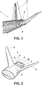
- Figure 1 shows a preferred embodiment of the proposed concept.
- a conventional fuselage is shaped so that its rear end fuselage (4) section has a flattened shape.
- a thruster assembly (3) is installed towards the end of the fuselage (4), between the fins of a v-tail (2) arrangement and the rearmost section of said rear end fuselage (4).
- the thruster assembly (3) comprises at least one propulsion device (5), a control surface (6), and a casing (7) defining an air inlet (8) and an air outlet (9) between the casing (7) and the propulsion device (5).
- the propulsion device (5) is installed to ingest and consume air forming the fuselage boundary layer.
- the control surface (6) is mounted at the rearmost section of the rear end to receive the exhaust (outflow) of the propulsion device (5), and thus provide vectoring thrust to the aircraft when the said control surface (6) is deflected.
- the casing (7) is designed to cover at least part of the propulsion device (5) to allow both the passage of the fuselage boundary layer towards the propulsion device (5) through the air inlet (8), and the passage of the airflow exhausted from the propulsion device (5) towards the control surface (6) through the air outlet (9).
- the thruster assembly casing (7) has a main surface (10) substantially parallel to the aircraft fuselage (4), and the casing (7) further comprises at least one flap (11) movable between two extreme positions, a close position wherein the flap (11) is aligned with the main surface of the casing (10), and an open position wherein the flap (11) is deflected, forming an angle with said main surface (10), to operate as an air-brake.
- control surface (6) is rotatably attached to the rearmost section of the rear end to provide a pitching movement to the aircraft.
- the technical advantage of this vectored thrust is to reduce the size of the empennage.
- the propulsion device (5) comprises an engine driving fluid mechanical devices, such as fans (13) or paddles (12), or electroaerodynamic devices, such as electromagnetic or plasma-dynamic actuators.
Landscapes
- Engineering & Computer Science (AREA)
- Aviation & Aerospace Engineering (AREA)
- Chemical & Material Sciences (AREA)
- Combustion & Propulsion (AREA)
- Mechanical Engineering (AREA)
- Physics & Mathematics (AREA)
- Fluid Mechanics (AREA)
- Structures Of Non-Positive Displacement Pumps (AREA)
- Control Of Turbines (AREA)
- Compositions Of Oxide Ceramics (AREA)
- Paper (AREA)
- Retarders (AREA)
- Tires In General (AREA)
Abstract
Description
- The present invention refers to a rear end for an aircraft including a boundary layer ingestion (BLI) engine adapted to operate as a thruster with the aid of a movable control surface, mounted after the exhaust of the BLI engine to modulate the flow and divert it in order to provide vector thrust.
- The main object of the present invention is to provide a rear end for an aircraft that is able of increasing the propulsive efficiency of conventional aircrafts, by ingesting the slow air in the fuselage boundary layer into some fluid mechanic thrusting devices, to increase the aircraft velocity, and reduce its usual energy consumption.
- Another object of the invention is to reduce the size of the rear end of an aircraft.
- The NASA STARC-ABL aircraft concept has a Boundary Layer Ingestion propulsion, where a conventional small engine (electric or thermal) drives a fan or rotor located at the end of a conical aft fuselage. This aircraft concept exhibits a T-tail. The European version of this project, known as CENTRELINE, is almost identical to the STARC-ABL concept.
- The NASA/MIT D8 aircraft exhibits a Boundary Layer Ingestion propulsive system on a flattened rear fuselage. In this case, the empennage is of a "Pi" tail configuration, and the engines installed at the rear end are primary propulsive engines installed to only ingest the boundary layer on the upper surface of the fuselage.
- Regarding thrust vectoring, there are several concepts and applications known in the prior art but none of them is related to an engine that also operates as a BLI engine.
- It would therefore be desirable to provide a technical solution that provides both an increase of the propulsive efficiency and thrust vectoring through the use of a BLI engine.
- The present invention overcomes the above mentioned drawbacks by providing a rear end section for an aircraft adapted to perform boundary layer ingestion at the time that provides vectoring thrust to the aircraft.
- The rear end section for an aircraft has a fuselage, a v-tail formed by two surfaces set in a v-shaped configuration, and a thruster assembly mounted on the rear end fuselage between the v-tail and the rearmost section of said rear end fuselage. The thruster assembly comprises at least one propulsion device installed to ingest the air from the boundary layer formed over the fuselage of the aircraft, a control surface attached at the rearmost section of the rear end, and a casing covering at least part of the propulsion device such that an air inlet and an air outlet are defined between the casing and the propulsion device. The air inlet is designed for the passage of the fuselage boundary layer towards the propulsion device, and the air outlet is designed for directing the airflow exhausted from the propulsion device towards the control surface, to divert said airflow in order to provide vectoring thrust for the aircraft.
- The invention provides an aircraft rear end with a propulsion device (engine) operating both as a BLI engine, by ingesting and consuming air forming a boundary layer over the fuselage of the aircraft, and also as a vectoring thruster with the aid of a control surface mounted to receive the engine slipstream, blowing over said control surface.
- The invention increases the propulsive efficiency of the aircraft, and thus decreases its fuel consumption. The increment in linear momentum of the air of the boundary layer effected by the BLI engine generates thrust but the air in the slipstream has a lower velocity than it would be required in order to impart this momentum jump to free-stream air, thus leaving less kinetic energy in the slipstream and helping to reduce the energy consumption to generate a given amount of thrust.
- Preferably, the at least one propulsion device will consist of an array of engines in order to improve the boundary layer capture efficiency, and to reduce the size and cost of each of the engines.
- Additionally, using the BLI concept and adapting it to produce thrust vectoring, allows reducing the size of the empennage, with a consequent reduction of weight, drag and cost of the aircraft.
- For a better comprehension of the invention, the following drawings are provided for illustrative and non-limiting purposes, wherein:
-
Figure 1 shows a perspective view of the aircraft rear end section of the aircraft. -
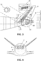
Figure 2 shows an upper perspective view of the rear end section of the aircraft. -
Figure 3 shows a schematic longitudinal section view of the rear end section of the aircraft. -
Figure 4 shows a rear view of the rear end section of the aircraft. -
Figure 1 shows a preferred embodiment of the proposed concept. A conventional fuselage is shaped so that its rear end fuselage (4) section has a flattened shape. A thruster assembly (3) is installed towards the end of the fuselage (4), between the fins of a v-tail (2) arrangement and the rearmost section of said rear end fuselage (4). - As seen in
Figure 2 , the thruster assembly (3) comprises at least one propulsion device (5), a control surface (6), and a casing (7) defining an air inlet (8) and an air outlet (9) between the casing (7) and the propulsion device (5). - The propulsion device (5) is installed to ingest and consume air forming the fuselage boundary layer. The control surface (6) is mounted at the rearmost section of the rear end to receive the exhaust (outflow) of the propulsion device (5), and thus provide vectoring thrust to the aircraft when the said control surface (6) is deflected. The casing (7) is designed to cover at least part of the propulsion device (5) to allow both the passage of the fuselage boundary layer towards the propulsion device (5) through the air inlet (8), and the passage of the airflow exhausted from the propulsion device (5) towards the control surface (6) through the air outlet (9).
- As shown in
Figure 3 and according to a preferred embodiment, the thruster assembly casing (7) has a main surface (10) substantially parallel to the aircraft fuselage (4), and the casing (7) further comprises at least one flap (11) movable between two extreme positions, a close position wherein the flap (11) is aligned with the main surface of the casing (10), and an open position wherein the flap (11) is deflected, forming an angle with said main surface (10), to operate as an air-brake. - According to another preferred embodiment, the control surface (6) is rotatably attached to the rearmost section of the rear end to provide a pitching movement to the aircraft. The technical advantage of this vectored thrust is to reduce the size of the empennage.
- Finally, as shown in
Figures 2-4 and according to another preferred embodiment, the propulsion device (5) comprises an engine driving fluid mechanical devices, such as fans (13) or paddles (12), or electroaerodynamic devices, such as electromagnetic or plasma-dynamic actuators.
Claims (4)
- A rear end section (1) for an aircraft, having a fuselage (4), a v-tail configuration (2), and a thruster assembly (3) mounted on the rear end fuselage (4) between the v-tail (2) and the rearmost section of said rear end fuselage (4), wherein the thruster assembly (3) comprises:- at least one propulsion device (5) installed to ingest and consume air forming a fuselage boundary layer,- a control surface (6) attached at the rearmost section of the rear end,- a casing (7) covering at least part of the propulsion device (5) such that an air inlet (8) and an air outlet (9) are defined between the casing (7) and the propulsion device (5), the air inlet (8) being designed for the passage of the fuselage boundary layer towards the propulsion device (5), and the air outlet (9) being designed for directing the airflow exhausted from the propulsion device (5) towards the control surface (6) to divert said airflow and provide vectoring thrust for the aircraft.
- A rear end section (1) for an aircraft, according to claim 1, wherein the thruster assembly casing (7) has a main surface (10) substantially parallel to the aircraft fuselage (4), and wherein the casing (7) further comprises at least one flap (11) movable between two extreme positions, a close position wherein the flap (11) is aligned with the main surface of the casing (10), and an open position wherein the flap (11) is deflected, forming an angle with said main surface (10), to operate as an air-brake.
- A rear end section (1) for an aircraft, according to any preceding claims, wherein the control surface (6) is rotatable attached to the rearmost section of the rear end to provide a pitching movement to the aircraft.
- A rear end section (1) for an aircraft, according to any preceding claims, wherein the propulsion device (5) comprises an engine driving fluid mechanical devices, such as fans (13) or paddles (12), or electroaerodynamic devices, such as electromagnetic or plasma-dynamic actuators.
Priority Applications (3)
| Application Number | Priority Date | Filing Date | Title |
|---|---|---|---|
| ES20382351T ES2949800T3 (en) | 2020-04-29 | 2020-04-29 | Rear end section of an aircraft |
| EP20382351.3A EP3904202B1 (en) | 2020-04-29 | 2020-04-29 | A rear end section for an aircraft |
| US17/241,579 US20210339844A1 (en) | 2020-04-29 | 2021-04-27 | Rear end section for an aircraft |
Applications Claiming Priority (1)
| Application Number | Priority Date | Filing Date | Title |
|---|---|---|---|
| EP20382351.3A EP3904202B1 (en) | 2020-04-29 | 2020-04-29 | A rear end section for an aircraft |
Publications (2)
| Publication Number | Publication Date |
|---|---|
| EP3904202A1 true EP3904202A1 (en) | 2021-11-03 |
| EP3904202B1 EP3904202B1 (en) | 2023-06-07 |
Family
ID=70480205
Family Applications (1)
| Application Number | Title | Priority Date | Filing Date |
|---|---|---|---|
| EP20382351.3A Active EP3904202B1 (en) | 2020-04-29 | 2020-04-29 | A rear end section for an aircraft |
Country Status (3)
| Country | Link |
|---|---|
| US (1) | US20210339844A1 (en) |
| EP (1) | EP3904202B1 (en) |
| ES (1) | ES2949800T3 (en) |
Citations (4)
| Publication number | Priority date | Publication date | Assignee | Title |
|---|---|---|---|---|
| US2780424A (en) * | 1951-10-19 | 1957-02-05 | Lockheed Aircraft Corp | Airplane for vertical take-off in horizontal attitude |
| US20120138736A1 (en) * | 2009-03-12 | 2012-06-07 | Airbus Operations (S.A.S.) | Airplane with a tailcoat tail assembly and rear engine |
| US20130062455A1 (en) * | 2005-04-20 | 2013-03-14 | Richard H. Lugg | Hybrid jet/electric vtol aircraft |
| US20160332741A1 (en) * | 2015-05-13 | 2016-11-17 | Rolls-Royce Plc | Aircraft |
Family Cites Families (18)
| Publication number | Priority date | Publication date | Assignee | Title |
|---|---|---|---|---|
| US1485649A (en) * | 1923-02-15 | 1924-03-04 | Pieter Barteld Van Leggelo | Means for use in propelling aeroplanes, hydroplanes, and other conveyances |
| US1639908A (en) * | 1925-08-25 | 1927-08-23 | Strandgren Carl Bruno | Turbine-wheel propeller and motor |
| US2035175A (en) * | 1934-11-08 | 1936-03-24 | Robert J Mclaughlin | Aeronautical wheel |
| US3325123A (en) * | 1961-05-19 | 1967-06-13 | Fay E Null | Magnetohydrodynamic control |
| US3276696A (en) * | 1962-08-21 | 1966-10-04 | Bert K Brandt | Jet engine thrust modification |
| GB1397068A (en) * | 1971-06-24 | 1975-06-11 | Hawker Siddeley Aviation Ltd | Aircraft |
| US4005823A (en) * | 1975-09-30 | 1977-02-01 | United Technologies Corporation | Flap-type two-dimensional nozzle having a plug |
| GB1581048A (en) * | 1977-11-09 | 1980-12-10 | Rolls Royce | Aircraft |
| DE102006025752A1 (en) * | 2006-05-31 | 2007-12-06 | Airbus Deutschland Gmbh | Method and apparatus for generating aerodynamic drag on an aircraft |
| US8016247B2 (en) * | 2007-05-25 | 2011-09-13 | The Boeing Company | Plasma flow control actuator system and method |
| US8231079B2 (en) * | 2008-03-31 | 2012-07-31 | Honda Patents & Technologies North America, Llc | Aerodynamic braking device for aircraft |
| FR3006997B1 (en) * | 2013-06-14 | 2016-12-23 | Airbus | AIRCRAFT WITH ELECTRICAL PROPULSION MEANS |
| EP3321186A1 (en) * | 2016-11-14 | 2018-05-16 | Airbus Operations GmbH | Aircraft |
| FR3061146B1 (en) * | 2016-12-23 | 2023-11-03 | Airbus Operations Sas | REAR-ENGINED AIRCRAFT CARRIED BY AT LEAST ONE ARM IN A POSITION OFFSET BACKWARDS AND AT A DISTANCE FROM A REAR END OF THE AIRCRAFT’S AIRCRAFT |
| US10718272B2 (en) * | 2017-04-18 | 2020-07-21 | United Technologies Corporation | Variable-geometry boundary layer diverter |
| EP3666645B1 (en) * | 2018-12-14 | 2021-11-17 | Bombardier Inc. | Forward swept wing aircraft with boundary layer ingestion and distributed electrical propulsion system |
| US20200189719A1 (en) * | 2018-12-17 | 2020-06-18 | The Boeing Company | Brake systems for aircraft and related methods |
| US11492099B2 (en) * | 2019-04-19 | 2022-11-08 | Wright Electric, Inc. | Aircraft nacelle having electric motor and thrust reversing air exhaust flaps |
-
2020
- 2020-04-29 EP EP20382351.3A patent/EP3904202B1/en active Active
- 2020-04-29 ES ES20382351T patent/ES2949800T3/en active Active
-
2021
- 2021-04-27 US US17/241,579 patent/US20210339844A1/en not_active Abandoned
Patent Citations (4)
| Publication number | Priority date | Publication date | Assignee | Title |
|---|---|---|---|---|
| US2780424A (en) * | 1951-10-19 | 1957-02-05 | Lockheed Aircraft Corp | Airplane for vertical take-off in horizontal attitude |
| US20130062455A1 (en) * | 2005-04-20 | 2013-03-14 | Richard H. Lugg | Hybrid jet/electric vtol aircraft |
| US20120138736A1 (en) * | 2009-03-12 | 2012-06-07 | Airbus Operations (S.A.S.) | Airplane with a tailcoat tail assembly and rear engine |
| US20160332741A1 (en) * | 2015-05-13 | 2016-11-17 | Rolls-Royce Plc | Aircraft |
Also Published As
| Publication number | Publication date |
|---|---|
| EP3904202B1 (en) | 2023-06-07 |
| ES2949800T3 (en) | 2023-10-03 |
| US20210339844A1 (en) | 2021-11-04 |
Similar Documents
| Publication | Publication Date | Title |
|---|---|---|
| US11987352B2 (en) | Fluid systems that include a co-flow jet | |
| JP6930743B2 (en) | Ejector and airfoil shape | |
| US11111025B2 (en) | Fluid systems that prevent the formation of ice | |
| US6622973B2 (en) | Movable surface plane | |
| US10358229B2 (en) | Aircraft | |
| US6082670A (en) | Method and arrangement for fluidborne vehicle propulsion and drag reduction | |
| EP2808253B1 (en) | Helicopter with cross flow fan | |
| CN109421920B (en) | Aircraft propulsion system and method | |
| US20110147533A1 (en) | Morphing ducted fan for vertical take-off and landing vehicle | |
| US8157520B2 (en) | Fan, airfoil and vehicle propulsion systems | |
| JP2008518828A (en) | High lift distributed active flow control system and method | |
| CN111727312A (en) | Configuration of vertical take-off and landing system of aircraft | |
| EP2412628B1 (en) | Aerospace vehicle yaw generating tail section | |
| US20210339844A1 (en) | Rear end section for an aircraft | |
| JP7576384B2 (en) | Utilizing airflow assemblies with intermittent thrusters | |
| CN111655580A (en) | Winglet Jet Construction |
Legal Events
| Date | Code | Title | Description |
|---|---|---|---|
| PUAI | Public reference made under article 153(3) epc to a published international application that has entered the european phase |
Free format text: ORIGINAL CODE: 0009012 |
|
| STAA | Information on the status of an ep patent application or granted ep patent |
Free format text: STATUS: THE APPLICATION HAS BEEN PUBLISHED |
|
| AK | Designated contracting states |
Kind code of ref document: A1 Designated state(s): AL AT BE BG CH CY CZ DE DK EE ES FI FR GB GR HR HU IE IS IT LI LT LU LV MC MK MT NL NO PL PT RO RS SE SI SK SM TR |
|
| B565 | Issuance of search results under rule 164(2) epc |
Effective date: 20201022 |
|
| STAA | Information on the status of an ep patent application or granted ep patent |
Free format text: STATUS: REQUEST FOR EXAMINATION WAS MADE |
|
| 17P | Request for examination filed |
Effective date: 20220325 |
|
| RBV | Designated contracting states (corrected) |
Designated state(s): AL AT BE BG CH CY CZ DE DK EE ES FI FR GB GR HR HU IE IS IT LI LT LU LV MC MK MT NL NO PL PT RO RS SE SI SK SM TR |
|
| GRAP | Despatch of communication of intention to grant a patent |
Free format text: ORIGINAL CODE: EPIDOSNIGR1 |
|
| STAA | Information on the status of an ep patent application or granted ep patent |
Free format text: STATUS: GRANT OF PATENT IS INTENDED |
|
| RIC1 | Information provided on ipc code assigned before grant |
Ipc: B64D 27/14 19680901ALI20230111BHEP Ipc: B64C 21/06 19680901ALI20230111BHEP Ipc: B64C 9/38 19680901ALI20230111BHEP Ipc: B64C 1/00 19680901ALI20230111BHEP Ipc: B64C 1/06 19680901AFI20230111BHEP |
|
| INTG | Intention to grant announced |
Effective date: 20230203 |
|
| GRAS | Grant fee paid |
Free format text: ORIGINAL CODE: EPIDOSNIGR3 |
|
| GRAA | (expected) grant |
Free format text: ORIGINAL CODE: 0009210 |
|
| STAA | Information on the status of an ep patent application or granted ep patent |
Free format text: STATUS: THE PATENT HAS BEEN GRANTED |
|
| AK | Designated contracting states |
Kind code of ref document: B1 Designated state(s): AL AT BE BG CH CY CZ DE DK EE ES FI FR GB GR HR HU IE IS IT LI LT LU LV MC MK MT NL NO PL PT RO RS SE SI SK SM TR |
|
| REG | Reference to a national code |
Ref country code: GB Ref legal event code: FG4D |
|
| REG | Reference to a national code |
Ref country code: CH Ref legal event code: EP Ref country code: AT Ref legal event code: REF Ref document number: 1574247 Country of ref document: AT Kind code of ref document: T Effective date: 20230615 Ref country code: DE Ref legal event code: R096 Ref document number: 602020011828 Country of ref document: DE |
|
| REG | Reference to a national code |
Ref country code: LT Ref legal event code: MG9D |
|
| REG | Reference to a national code |
Ref country code: ES Ref legal event code: FG2A Ref document number: 2949800 Country of ref document: ES Kind code of ref document: T3 Effective date: 20231003 |
|
| REG | Reference to a national code |
Ref country code: NL Ref legal event code: MP Effective date: 20230607 |
|
| PG25 | Lapsed in a contracting state [announced via postgrant information from national office to epo] |
Ref country code: SE Free format text: LAPSE BECAUSE OF FAILURE TO SUBMIT A TRANSLATION OF THE DESCRIPTION OR TO PAY THE FEE WITHIN THE PRESCRIBED TIME-LIMIT Effective date: 20230607 Ref country code: NO Free format text: LAPSE BECAUSE OF FAILURE TO SUBMIT A TRANSLATION OF THE DESCRIPTION OR TO PAY THE FEE WITHIN THE PRESCRIBED TIME-LIMIT Effective date: 20230907 |
|
| REG | Reference to a national code |
Ref country code: AT Ref legal event code: MK05 Ref document number: 1574247 Country of ref document: AT Kind code of ref document: T Effective date: 20230607 |
|
| PG25 | Lapsed in a contracting state [announced via postgrant information from national office to epo] |
Ref country code: RS Free format text: LAPSE BECAUSE OF FAILURE TO SUBMIT A TRANSLATION OF THE DESCRIPTION OR TO PAY THE FEE WITHIN THE PRESCRIBED TIME-LIMIT Effective date: 20230607 Ref country code: NL Free format text: LAPSE BECAUSE OF FAILURE TO SUBMIT A TRANSLATION OF THE DESCRIPTION OR TO PAY THE FEE WITHIN THE PRESCRIBED TIME-LIMIT Effective date: 20230607 Ref country code: LV Free format text: LAPSE BECAUSE OF FAILURE TO SUBMIT A TRANSLATION OF THE DESCRIPTION OR TO PAY THE FEE WITHIN THE PRESCRIBED TIME-LIMIT Effective date: 20230607 Ref country code: LT Free format text: LAPSE BECAUSE OF FAILURE TO SUBMIT A TRANSLATION OF THE DESCRIPTION OR TO PAY THE FEE WITHIN THE PRESCRIBED TIME-LIMIT Effective date: 20230607 Ref country code: HR Free format text: LAPSE BECAUSE OF FAILURE TO SUBMIT A TRANSLATION OF THE DESCRIPTION OR TO PAY THE FEE WITHIN THE PRESCRIBED TIME-LIMIT Effective date: 20230607 |
|
| PG25 | Lapsed in a contracting state [announced via postgrant information from national office to epo] |
Ref country code: FI Free format text: LAPSE BECAUSE OF FAILURE TO SUBMIT A TRANSLATION OF THE DESCRIPTION OR TO PAY THE FEE WITHIN THE PRESCRIBED TIME-LIMIT Effective date: 20230607 |
|
| PG25 | Lapsed in a contracting state [announced via postgrant information from national office to epo] |
Ref country code: SK Free format text: LAPSE BECAUSE OF FAILURE TO SUBMIT A TRANSLATION OF THE DESCRIPTION OR TO PAY THE FEE WITHIN THE PRESCRIBED TIME-LIMIT Effective date: 20230607 |
|
| PG25 | Lapsed in a contracting state [announced via postgrant information from national office to epo] |
Ref country code: IS Free format text: LAPSE BECAUSE OF FAILURE TO SUBMIT A TRANSLATION OF THE DESCRIPTION OR TO PAY THE FEE WITHIN THE PRESCRIBED TIME-LIMIT Effective date: 20231007 |
|
| PG25 | Lapsed in a contracting state [announced via postgrant information from national office to epo] |
Ref country code: SM Free format text: LAPSE BECAUSE OF FAILURE TO SUBMIT A TRANSLATION OF THE DESCRIPTION OR TO PAY THE FEE WITHIN THE PRESCRIBED TIME-LIMIT Effective date: 20230607 Ref country code: SK Free format text: LAPSE BECAUSE OF FAILURE TO SUBMIT A TRANSLATION OF THE DESCRIPTION OR TO PAY THE FEE WITHIN THE PRESCRIBED TIME-LIMIT Effective date: 20230607 Ref country code: RO Free format text: LAPSE BECAUSE OF FAILURE TO SUBMIT A TRANSLATION OF THE DESCRIPTION OR TO PAY THE FEE WITHIN THE PRESCRIBED TIME-LIMIT Effective date: 20230607 Ref country code: PT Free format text: LAPSE BECAUSE OF FAILURE TO SUBMIT A TRANSLATION OF THE DESCRIPTION OR TO PAY THE FEE WITHIN THE PRESCRIBED TIME-LIMIT Effective date: 20231009 Ref country code: IS Free format text: LAPSE BECAUSE OF FAILURE TO SUBMIT A TRANSLATION OF THE DESCRIPTION OR TO PAY THE FEE WITHIN THE PRESCRIBED TIME-LIMIT Effective date: 20231007 Ref country code: EE Free format text: LAPSE BECAUSE OF FAILURE TO SUBMIT A TRANSLATION OF THE DESCRIPTION OR TO PAY THE FEE WITHIN THE PRESCRIBED TIME-LIMIT Effective date: 20230607 Ref country code: CZ Free format text: LAPSE BECAUSE OF FAILURE TO SUBMIT A TRANSLATION OF THE DESCRIPTION OR TO PAY THE FEE WITHIN THE PRESCRIBED TIME-LIMIT Effective date: 20230607 Ref country code: AT Free format text: LAPSE BECAUSE OF FAILURE TO SUBMIT A TRANSLATION OF THE DESCRIPTION OR TO PAY THE FEE WITHIN THE PRESCRIBED TIME-LIMIT Effective date: 20230607 |
|
| PG25 | Lapsed in a contracting state [announced via postgrant information from national office to epo] |
Ref country code: PL Free format text: LAPSE BECAUSE OF FAILURE TO SUBMIT A TRANSLATION OF THE DESCRIPTION OR TO PAY THE FEE WITHIN THE PRESCRIBED TIME-LIMIT Effective date: 20230607 |
|
| REG | Reference to a national code |
Ref country code: DE Ref legal event code: R097 Ref document number: 602020011828 Country of ref document: DE |
|
| PLBE | No opposition filed within time limit |
Free format text: ORIGINAL CODE: 0009261 |
|
| STAA | Information on the status of an ep patent application or granted ep patent |
Free format text: STATUS: NO OPPOSITION FILED WITHIN TIME LIMIT |
|
| PG25 | Lapsed in a contracting state [announced via postgrant information from national office to epo] |
Ref country code: DK Free format text: LAPSE BECAUSE OF FAILURE TO SUBMIT A TRANSLATION OF THE DESCRIPTION OR TO PAY THE FEE WITHIN THE PRESCRIBED TIME-LIMIT Effective date: 20230607 |
|
| PG25 | Lapsed in a contracting state [announced via postgrant information from national office to epo] |
Ref country code: SI Free format text: LAPSE BECAUSE OF FAILURE TO SUBMIT A TRANSLATION OF THE DESCRIPTION OR TO PAY THE FEE WITHIN THE PRESCRIBED TIME-LIMIT Effective date: 20230607 |
|
| 26N | No opposition filed |
Effective date: 20240308 |
|
| PG25 | Lapsed in a contracting state [announced via postgrant information from national office to epo] |
Ref country code: SI Free format text: LAPSE BECAUSE OF FAILURE TO SUBMIT A TRANSLATION OF THE DESCRIPTION OR TO PAY THE FEE WITHIN THE PRESCRIBED TIME-LIMIT Effective date: 20230607 Ref country code: IT Free format text: LAPSE BECAUSE OF FAILURE TO SUBMIT A TRANSLATION OF THE DESCRIPTION OR TO PAY THE FEE WITHIN THE PRESCRIBED TIME-LIMIT Effective date: 20230607 |
|
| PG25 | Lapsed in a contracting state [announced via postgrant information from national office to epo] |
Ref country code: BG Free format text: LAPSE BECAUSE OF FAILURE TO SUBMIT A TRANSLATION OF THE DESCRIPTION OR TO PAY THE FEE WITHIN THE PRESCRIBED TIME-LIMIT Effective date: 20230607 |
|
| PG25 | Lapsed in a contracting state [announced via postgrant information from national office to epo] |
Ref country code: MC Free format text: LAPSE BECAUSE OF FAILURE TO SUBMIT A TRANSLATION OF THE DESCRIPTION OR TO PAY THE FEE WITHIN THE PRESCRIBED TIME-LIMIT Effective date: 20230607 |
|
| PG25 | Lapsed in a contracting state [announced via postgrant information from national office to epo] |
Ref country code: MC Free format text: LAPSE BECAUSE OF FAILURE TO SUBMIT A TRANSLATION OF THE DESCRIPTION OR TO PAY THE FEE WITHIN THE PRESCRIBED TIME-LIMIT Effective date: 20230607 Ref country code: BG Free format text: LAPSE BECAUSE OF FAILURE TO SUBMIT A TRANSLATION OF THE DESCRIPTION OR TO PAY THE FEE WITHIN THE PRESCRIBED TIME-LIMIT Effective date: 20230607 |
|
| REG | Reference to a national code |
Ref country code: CH Ref legal event code: PL |
|
| PG25 | Lapsed in a contracting state [announced via postgrant information from national office to epo] |
Ref country code: LU Free format text: LAPSE BECAUSE OF NON-PAYMENT OF DUE FEES Effective date: 20240429 |
|
| REG | Reference to a national code |
Ref country code: BE Ref legal event code: MM Effective date: 20240430 |
|
| PG25 | Lapsed in a contracting state [announced via postgrant information from national office to epo] |
Ref country code: LU Free format text: LAPSE BECAUSE OF NON-PAYMENT OF DUE FEES Effective date: 20240429 |
|
| PG25 | Lapsed in a contracting state [announced via postgrant information from national office to epo] |
Ref country code: BE Free format text: LAPSE BECAUSE OF NON-PAYMENT OF DUE FEES Effective date: 20240430 |
|
| PG25 | Lapsed in a contracting state [announced via postgrant information from national office to epo] |
Ref country code: BE Free format text: LAPSE BECAUSE OF NON-PAYMENT OF DUE FEES Effective date: 20240430 Ref country code: CH Free format text: LAPSE BECAUSE OF NON-PAYMENT OF DUE FEES Effective date: 20240430 |
|
| PG25 | Lapsed in a contracting state [announced via postgrant information from national office to epo] |
Ref country code: IE Free format text: LAPSE BECAUSE OF NON-PAYMENT OF DUE FEES Effective date: 20240429 |
|
| PGFP | Annual fee paid to national office [announced via postgrant information from national office to epo] |
Ref country code: DE Payment date: 20250422 Year of fee payment: 6 |
|
| PGFP | Annual fee paid to national office [announced via postgrant information from national office to epo] |
Ref country code: GB Payment date: 20250423 Year of fee payment: 6 Ref country code: ES Payment date: 20250530 Year of fee payment: 6 |
|
| PGFP | Annual fee paid to national office [announced via postgrant information from national office to epo] |
Ref country code: FR Payment date: 20250425 Year of fee payment: 6 |
|
| PG25 | Lapsed in a contracting state [announced via postgrant information from national office to epo] |
Ref country code: CY Free format text: LAPSE BECAUSE OF FAILURE TO SUBMIT A TRANSLATION OF THE DESCRIPTION OR TO PAY THE FEE WITHIN THE PRESCRIBED TIME-LIMIT; INVALID AB INITIO Effective date: 20200429 |
|
| PG25 | Lapsed in a contracting state [announced via postgrant information from national office to epo] |
Ref country code: HU Free format text: LAPSE BECAUSE OF FAILURE TO SUBMIT A TRANSLATION OF THE DESCRIPTION OR TO PAY THE FEE WITHIN THE PRESCRIBED TIME-LIMIT; INVALID AB INITIO Effective date: 20200429 |
|
| PG25 | Lapsed in a contracting state [announced via postgrant information from national office to epo] |
Ref country code: GR Free format text: LAPSE BECAUSE OF FAILURE TO SUBMIT A TRANSLATION OF THE DESCRIPTION OR TO PAY THE FEE WITHIN THE PRESCRIBED TIME-LIMIT; INVALID AB INITIO Effective date: 20200429 |