EP3904176A1 - Seat mounting structure and train having same - Google Patents
Seat mounting structure and train having same Download PDFInfo
- Publication number
- EP3904176A1 EP3904176A1 EP19913916.3A EP19913916A EP3904176A1 EP 3904176 A1 EP3904176 A1 EP 3904176A1 EP 19913916 A EP19913916 A EP 19913916A EP 3904176 A1 EP3904176 A1 EP 3904176A1
- Authority
- EP
- European Patent Office
- Prior art keywords
- side wall
- seat
- seat body
- carriage
- mounting
- Prior art date
- Legal status (The legal status is an assumption and is not a legal conclusion. Google has not performed a legal analysis and makes no representation as to the accuracy of the status listed.)
- Pending
Links
Images


Classifications
-
- B—PERFORMING OPERATIONS; TRANSPORTING
- B61—RAILWAYS
- B61D—BODY DETAILS OR KINDS OF RAILWAY VEHICLES
- B61D33/00—Seats
- B61D33/0057—Seats characterised by their mounting in vehicles
- B61D33/0064—Seats characterised by their mounting in vehicles not adjustably mounted; supports therefor
-
- B—PERFORMING OPERATIONS; TRANSPORTING
- B60—VEHICLES IN GENERAL
- B60N—SEATS SPECIALLY ADAPTED FOR VEHICLES; VEHICLE PASSENGER ACCOMMODATION NOT OTHERWISE PROVIDED FOR
- B60N2/00—Seats specially adapted for vehicles; Arrangement or mounting of seats in vehicles
- B60N2/24—Seats specially adapted for vehicles; Arrangement or mounting of seats in vehicles for particular purposes or particular vehicles
- B60N2/242—Bus seats
-
- B—PERFORMING OPERATIONS; TRANSPORTING
- B61—RAILWAYS
- B61D—BODY DETAILS OR KINDS OF RAILWAY VEHICLES
- B61D33/00—Seats
- B61D33/0007—Details; Accessories
- B61D33/0014—Seat frames
Definitions
- the present invention relates to the field of train apparatuses, in particular to a seat mounting structure and a train having same.
- Rail transit refers to a means of transport or transportation system in which an operating vehicle needs to travel on a particular rail.
- the most typical rail transit is a railway system consisting of traditional trains and standard railways. As the train and railway technologies develop diversely, the rail transit also becomes increasingly diversified. It is spread over long-distance land transportation, and is also widely applied to medium and short-distance urban public transportation.
- a transverse seat can provide a more comfortable seat environment than a longitudinal seat.
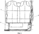
- a traditional transverse seat 1 needs to be fixed at the train side wall 2, and moreover, a support leg 3 needs to be additionally provided on the aisle side.
- the support leg 3 of the transverse seat 1 influences the attractiveness and increase the actual space occupation, which hinders the arrangement of other structures.
- the transverse seat structure is improved to a cantilever seat 4, since the support leg at the aisle is omitted, the strength of the seat is guaranteed by additionally arranging a support member 5 at the side wall, and a common structure is provided with a T-shaped support and an inclined supporting beam.
- the improved cantilever seat 4 is compact in structure, smaller in occupied space and more convenient to clean from below.
- the size of the mounting base at the side wall is increased due to the cantilever seat, and a cover plate is usually required to be mounted to shield the mounting base, which influences the overall sealing of the side wall while the attractiveness is influenced, and the overall weight is also increased.
- the support area of the mounting base at the side wall is limited, and therefore cannot provide effective support for the aisle side of the seat. Consequently, the seat obviously sinks when used, which affects riding comfort. Meanwhile, the structural strength of the cantilever seat has certain defects.
- the objective of the present invention provides a seat mounting structure and a train having same so as to solve the problem of low structural strength of a cantilever seat in the related art.
- a first aspect of the present invention provides a seat mounting structure, including: a seat body; a side wall mounting member, wherein a first end of the seat body is connected to a carriage side wall by the side wall mounting member; and a suspension mounting rod, wherein one end of the suspension mounting rod is connected to a carriage roof, and the other end of the suspension mounting rod is connected to a second end of the seat body; wherein the first end of the seat body is one end, close to the carriage side wall, of the seat body, and the second end of the seat body is one end, away from the carriage side wall, of the seat body.
- a plurality of the side wall mounting members are provided, and the first end of the seat body is fixedly connected to the carriage side wall by the plurality of side wall mounting members.
- the plurality of side wall mounting members are arranged at intervals in a height direction of the carriage side wall.
- the seat body includes a bottom plate and a backrest; wherein the plurality of side wall mounting members include a first side wall mounting member, and the bottom plate is fixedly connected to the carriage side wall by the first side wall mounting member.
- the first side wall mounting member includes a connector and a fastener, the connector being connected to the seat body, and the fastener penetrating the connector and the carriage side wall.
- the carriage side wall includes a shield plate
- the connector is a bent plate
- the fastener is a fastening bolt, the fastening bolt penetrating the bent plate and the shield plate to fasten the bent plate and the shield plate.
- the seat body includes opposite two side plate portions, the two side plate portions defining a seating area for accommodating a passenger; and the connector is connected to a bottom of the side plate portion, close to the carriage side wall, of the seat body.
- the plurality of side wall mounting members further include a second side wall mounting member, and the backrest is fixedly connected to the carriage side wall by the second side wall mounting member.
- the seat body includes opposite two side plate portions, the two side plate portions defining a seating area for accommodating a passenger; and the second side wall mounting member penetrates the side plate portion, close to the carriage side wall, of the seat body and the carriage side wall.
- the second side wall mounting member has a threaded rod section, a threaded stud is provided on the carriage side wall, and the second side wall mounting member penetrates the side plate portion and the shield plate of the carriage side wall and then is in threaded connection to the threaded stud.
- the seat body includes opposite two side plate portions, the two side plate portions defining a seating area for accommodating a passenger; and the first end of the seat body is the side plate portion, close to the carriage side wall, of the seat body, and the second end of the seat body is one end, away from the carriage side wall, of a top of the seat body.
- a top cross beam is provided on the seat body, and the second end of the seat body is one end, away from the carriage side wall, of the top cross beam.
- a shield plate is provided on the carriage side wall, and the shield plate is arranged in a vertical direction and opposite to the backrest; wherein the second side wall mounting member penetrates into the shield plate so as to fixedly connect the backrest to the carriage side wall.
- a boss structure is provided at a bottom of the carriage side wall, and the boss structure extends in an extension direction of the carriage side wall; wherein the first side wall mounting member abuts against an upper surface of the boss structure.
- the seat body includes a bottom plate and a backrest; wherein the suspension mounting rod is connected to the backrest.
- an end of the suspension mounting rod is provided with an articulated element, and the suspension mounting rod is hinged to the seat body by the articulated element.
- the embodiment of the present invention provides a seat mounting structure.
- the seat mounting structure includes: a seat body; a side wall mounting member, wherein a side of the seat body is connected to a carriage side wall by the side wall mounting member; and a suspension mounting rod, wherein one end of the suspension mounting rod is connected to a carriage roof, and the other end of the suspension mounting rod is connected to a top of the seat body.
- a second aspect of the present invention provides a train.
- the train includes a seat mounting structure which is the seat mounting structure mentioned above.
- the seat mounting structure applying the technical solution of the present invention includes a seat body, a side wall mounting member and a suspension mounting rod, wherein a first end of the seat body is connected to a carriage side wall by the side wall mounting member; one end of the suspension mounting rod is connected to a carriage roof, and the other end of the suspension mounting rod is connected to a second end of the seat body; wherein the first end of the seat body is one end, close to the carriage side wall, of the seat body, and the second end of the seat body is one end, away from the carriage side wall, of the seat body.
- the seat mounting structure may provide an effective support for a suspension seat to improve a structural strength of the suspension seat without increasing a size of a mounting base at the side wall. The problem of low structural strength of a cantilever seat in the related art is solved.
- the seat mounting structure includes a seat body 10, a side wall mounting member 20 and a suspension mounting rod 40, wherein a first end of the seat body 10 is connected to a carriage side wall 30 by the side wall mounting member 20; one end of the suspension mounting rod 40 is connected to a carriage roof, and the other end of the suspension mounting rod 40 is connected to a second end of the seat body 10; wherein the first end of the seat body 10 is one end, close to the carriage side wall 30, of the seat body 10, and the second end of the seat body 10 is one end, away from the carriage side wall 30, of the seat body 10.
- the seat mounting structure applying the technical solution of the present invention includes a seat body 10, a side wall mounting member 20 and a suspension mounting rod 40, wherein a first end of the seat body 10 is connected to a carriage side wall 30 by the side wall mounting member 20; one end of the suspension mounting rod 40 is connected to a carriage roof, and the other end of the suspension mounting rod 40 is connected to a second end of the seat body 10; wherein the first end of the seat body 10 is one end, close to the carriage side wall 30, of the seat body 10, and the second end of the seat body 10 is one end, away from the carriage side wall 30, of the seat body 10.
- the seat mounting structure may provide an effective support for a suspension seat to improve a structural strength of the suspension seat without increasing a size of a mounting base at the side wall. The problem of low structural strength of a cantilever seat in the related art is solved.
- the seat mounting structure is arranged as follows: a seat mounting structure includes a seat body 10; a side wall mounting member 20 and a suspension mounting rod 40, wherein a side of the seat body 10 is connected to a carriage side wall 30 by the side wall mounting member 20, one end of the suspension mounting rod 40 is connected to a carriage roof, and the other end of the suspension mounting rod 40 is connected to a top of the seat body 10.
- a plurality of the side wall mounting members 20 are provided, and the plurality of side wall mounting members 20 are arranged at intervals in a height direction of the carriage side wall 30.
- the first end of the seat body 10 is fixedly connected to the carriage side wall 30 by the side wall mounting members 20.
- the seat body 10 includes a bottom plate 11 and a backrest 12; the two side wall mounting members 20 are provided, the two side wall mounting members 20 include a first side wall mounting member 21 and a second side wall mounting member 22, the bottom plate 11 is fixedly connected to the carriage side wall 30 by the first side wall mounting member 21, and the backrest 12 is fixedly connected to the carriage side wall 30 by the second side wall mounting member 22.
- the plurality of side wall mounting members 20 are connected to the bottom plate 11 and the backrest 12 of the seat body 10 separately, thereby effectively improving the structural strength of connection, and guaranteeing the stability of the seat body 10.
- the first side wall mounting member 21 includes a connector 211 and a fastener 212, the connector 211 being connected to the seat body 10, and the fastener 212 penetrating the connector 211 and the carriage side wall 30.
- the carriage side wall 30 includes a shield plate 31, the connector 211 is a bent plate, and the fastener 212 is a fastening bolt, the fastening bolt penetrating the bent plate and the shield plate 31 to fasten the bent plate and the shield plate 31.
- the seat body 10 includes opposite two side plate portions 13, the two side plate portions 13 defining a seating area for accommodating a passenger; and the connector 211 is connected to a bottom of the side plate portion 13, close to the carriage side wall 30, of the seat body 10.
- a shield plate 31 is provided on the carriage side wall 30, and the shield plate 31 is arranged in the vertical direction and opposite to the backrest 12; wherein the second side wall mounting member 22 penetrates into the shield plate 31 so as to fixedly connect the backrest 12 to the carriage side wall 30; a boss structure 32 is arranged at a bottom of the carriage side wall 30, and the boss structure 32 extends in the extension direction of the carriage side wall 30; wherein the first side wall mounting member 21 abuts against an upper surface of the boss structure 32.
- the seat body 10 includes opposite two side plate portions 13, the two side plate portions 13 defining a seating area for accommodating a passenger; and the second side wall mounting member 22 penetrates the side plate portion 13, close to the carriage side wall 30, of the seat body 10 and the carriage side wall 30.
- the second side wall mounting member 22 has a threaded rod section, a threaded stud is provided on the carriage side wall 30, and the second side wall mounting member 22 penetrates the side plate portion 13 and the shield plate 31 of the carriage side wall 30 and then is in threaded connection to the threaded stud.
- the seat body 10 includes opposite two side plate portions 13, the two side plate portions 13 defining a seating area for accommodating a passenger; and the first end of the seat body 10 is the side plate portion 13, close to the carriage side wall 30, of the seat body 10, and the second end of the seat body 10 is one end, away from the carriage side wall 30, of a top of the seat body 10.
- a top cross beam 14 is provided on the seat body 10, and the second end of the seat body 10 is one end, away from the carriage side wall 30, of the top cross beam 14.
- an end of the suspension mounting rod 40 is provided with an articulated element, and the suspension mounting rod 40 is hinged to the seat body 10 by the articulated element.
- the end of the suspension mounting rod 40 is connected to the backrest 12, so as to suspend and support the second end of the seat body 10, thereby guaranteeing the reliability of the seat body 10.
- an upper portion and a lower portion of one side, close to the carriage side wall 30, of the seat body 10 are each provided with a side wall mounting member 20 for connecting the seat body 10 to the carriage side wall 30.
- One side, close to an aisle, of the seat body 10 is connected to the seat body 10 by the suspension mounting rod 40, and the suspension mounting rod 40 is connected to a top framework of a vehicle body, and the suspension mounting rod 40 may also be used as a grab rail.
- the seat body 10, the suspension mounting rod 40, the carriage side wall 30 and the top framework of the vehicle body are connected to form a closed structure.
- the structural strength of the full-cantilever seat is ensured.
- the entire structure is free of redundant mounting bases or connector, such that the structural strength is guaranteed, compactness, light weight and elegant appearance of the structure are guaranteed to the greatest extent, and the floor below the seat body 10 and the carriage side wall 30 are cleaned smoothly.
- a second aspect of the present invention provides a train.
- the train includes a seat mounting structure which is the seat mounting structure of the above embodiments.
- the train applying the seat mounting structure of the above embodiments may provide an effective support for a suspension seat to improve a structural strength of the suspension seat without increasing a size of a mounting base at the side wall.
- the problem of low structural strength of a cantilever seat in the related art is solved.
Landscapes
- Engineering & Computer Science (AREA)
- Mechanical Engineering (AREA)
- Aviation & Aerospace Engineering (AREA)
- Transportation (AREA)
- Seats For Vehicles (AREA)
Abstract
Description
- The present invention claims the priority of Chinese Patent Application No.
201910101631.5 201920165639.3, filed to the Chinese Patent Office on January 30, 2019 - The present invention relates to the field of train apparatuses, in particular to a seat mounting structure and a train having same.
- Rail transit refers to a means of transport or transportation system in which an operating vehicle needs to travel on a particular rail. The most typical rail transit is a railway system consisting of traditional trains and standard railways. As the train and railway technologies develop diversely, the rail transit also becomes increasingly diversified. It is spread over long-distance land transportation, and is also widely applied to medium and short-distance urban public transportation.
- In the seat design of an existing rail vehicle, a transverse seat can provide a more comfortable seat environment than a longitudinal seat. In order to guarantee the structural strength, as shown in
Fig. 1 , a traditional transverse seat 1 needs to be fixed at thetrain side wall 2, and moreover, asupport leg 3 needs to be additionally provided on the aisle side. Thesupport leg 3 of the transverse seat 1 influences the attractiveness and increase the actual space occupation, which hinders the arrangement of other structures. - As shown in
Fig. 2 , the transverse seat structure is improved to acantilever seat 4, since the support leg at the aisle is omitted, the strength of the seat is guaranteed by additionally arranging a support member 5 at the side wall, and a common structure is provided with a T-shaped support and an inclined supporting beam. The improvedcantilever seat 4 is compact in structure, smaller in occupied space and more convenient to clean from below. - However, the size of the mounting base at the side wall is increased due to the cantilever seat, and a cover plate is usually required to be mounted to shield the mounting base, which influences the overall sealing of the side wall while the attractiveness is influenced, and the overall weight is also increased. In addition, the support area of the mounting base at the side wall is limited, and therefore cannot provide effective support for the aisle side of the seat. Consequently, the seat obviously sinks when used, which affects riding comfort. Meanwhile, the structural strength of the cantilever seat has certain defects.
- The objective of the present invention provides a seat mounting structure and a train having same so as to solve the problem of low structural strength of a cantilever seat in the related art.
- For achieving the above objective, a first aspect of the present invention provides a seat mounting structure, including: a seat body; a side wall mounting member, wherein a first end of the seat body is connected to a carriage side wall by the side wall mounting member; and a suspension mounting rod, wherein one end of the suspension mounting rod is connected to a carriage roof, and the other end of the suspension mounting rod is connected to a second end of the seat body; wherein the first end of the seat body is one end, close to the carriage side wall, of the seat body, and the second end of the seat body is one end, away from the carriage side wall, of the seat body.
- In an embodiment, a plurality of the side wall mounting members are provided, and the first end of the seat body is fixedly connected to the carriage side wall by the plurality of side wall mounting members.
- In an embodiment, the plurality of side wall mounting members are arranged at intervals in a height direction of the carriage side wall.
- In an embodiment, the seat body includes a bottom plate and a backrest; wherein the plurality of side wall mounting members include a first side wall mounting member, and the bottom plate is fixedly connected to the carriage side wall by the first side wall mounting member.
- In an embodiment, the first side wall mounting member includes a connector and a fastener, the connector being connected to the seat body, and the fastener penetrating the connector and the carriage side wall.
- In an embodiment, the carriage side wall includes a shield plate, the connector is a bent plate, and the fastener is a fastening bolt, the fastening bolt penetrating the bent plate and the shield plate to fasten the bent plate and the shield plate.
- In an embodiment, the seat body includes opposite two side plate portions, the two side plate portions defining a seating area for accommodating a passenger; and the connector is connected to a bottom of the side plate portion, close to the carriage side wall, of the seat body.
- In an embodiment, the plurality of side wall mounting members further include a second side wall mounting member, and the backrest is fixedly connected to the carriage side wall by the second side wall mounting member.
- In an embodiment, the seat body includes opposite two side plate portions, the two side plate portions defining a seating area for accommodating a passenger; and the second side wall mounting member penetrates the side plate portion, close to the carriage side wall, of the seat body and the carriage side wall.
- In an embodiment, the second side wall mounting member has a threaded rod section, a threaded stud is provided on the carriage side wall, and the second side wall mounting member penetrates the side plate portion and the shield plate of the carriage side wall and then is in threaded connection to the threaded stud.
- In an embodiment, the seat body includes opposite two side plate portions, the two side plate portions defining a seating area for accommodating a passenger; and the first end of the seat body is the side plate portion, close to the carriage side wall, of the seat body, and the second end of the seat body is one end, away from the carriage side wall, of a top of the seat body.
- In an embodiment, a top cross beam is provided on the seat body, and the second end of the seat body is one end, away from the carriage side wall, of the top cross beam.
- In an embodiment, a shield plate is provided on the carriage side wall, and the shield plate is arranged in a vertical direction and opposite to the backrest; wherein the second side wall mounting member penetrates into the shield plate so as to fixedly connect the backrest to the carriage side wall.
- In an embodiment, a boss structure is provided at a bottom of the carriage side wall, and the boss structure extends in an extension direction of the carriage side wall; wherein the first side wall mounting member abuts against an upper surface of the boss structure.
- In an embodiment, the seat body includes a bottom plate and a backrest; wherein the suspension mounting rod is connected to the backrest.
- In an embodiment, an end of the suspension mounting rod is provided with an articulated element, and the suspension mounting rod is hinged to the seat body by the articulated element.
- The embodiment of the present invention provides a seat mounting structure. The seat mounting structure includes: a seat body; a side wall mounting member, wherein a side of the seat body is connected to a carriage side wall by the side wall mounting member; and a suspension mounting rod, wherein one end of the suspension mounting rod is connected to a carriage roof, and the other end of the suspension mounting rod is connected to a top of the seat body.
- A second aspect of the present invention provides a train. The train includes a seat mounting structure which is the seat mounting structure mentioned above.
- The seat mounting structure applying the technical solution of the present invention includes a seat body, a side wall mounting member and a suspension mounting rod, wherein a first end of the seat body is connected to a carriage side wall by the side wall mounting member; one end of the suspension mounting rod is connected to a carriage roof, and the other end of the suspension mounting rod is connected to a second end of the seat body; wherein the first end of the seat body is one end, close to the carriage side wall, of the seat body, and the second end of the seat body is one end, away from the carriage side wall, of the seat body. The seat mounting structure may provide an effective support for a suspension seat to improve a structural strength of the suspension seat without increasing a size of a mounting base at the side wall. The problem of low structural strength of a cantilever seat in the related art is solved.
- The accompanying drawings of the description forming a part of the present invention serve to provide a further understanding thereof, the illustrative embodiments of the present invention and the description of the illustrative embodiments serve to explain the present invention and are not to be construed as unduly limiting the present invention. In the drawings:
-
Fig. 1 is a schematic diagram of an existing seat mounting structure; -
Fig. 2 is a schematic diagram of another existing seat mounting structure; and -
Fig. 3 is a schematic diagram of an optional seat mounting structure according to an embodiment of the present invention. - The above-mentioned figures include the following reference numerals:
- 1. transverse seat; 2. train side wall; 3. support leg; 4. cantilever seat; 5. support member;
- 10. seat body; 11. bottom plate; 12. backrest; 13, side plate portion; 14. top cross beam; 20, side wall mounting member; 21. first side wall mounting member; 211. connector; 212. fastener; 22. second side wall mounting member; 30. carriage side wall; 31. shield plate; 32. boss structure; 40. suspension mounting rod.
- It should be noted that the embodiments of the present invention and the features of the embodiments is combined with each other without conflict. The present invention will be described in detail below with reference to the accompanying drawings in conjunction with embodiments.
- As shown in
Fig. 3 , the seat mounting structure according to the embodiment of the present invention includes aseat body 10, a sidewall mounting member 20 and asuspension mounting rod 40, wherein a first end of theseat body 10 is connected to acarriage side wall 30 by the sidewall mounting member 20; one end of thesuspension mounting rod 40 is connected to a carriage roof, and the other end of thesuspension mounting rod 40 is connected to a second end of theseat body 10; wherein the first end of theseat body 10 is one end, close to thecarriage side wall 30, of theseat body 10, and the second end of theseat body 10 is one end, away from thecarriage side wall 30, of theseat body 10. - The seat mounting structure applying the technical solution of the present invention includes a
seat body 10, a sidewall mounting member 20 and asuspension mounting rod 40, wherein a first end of theseat body 10 is connected to acarriage side wall 30 by the sidewall mounting member 20; one end of thesuspension mounting rod 40 is connected to a carriage roof, and the other end of thesuspension mounting rod 40 is connected to a second end of theseat body 10; wherein the first end of theseat body 10 is one end, close to thecarriage side wall 30, of theseat body 10, and the second end of theseat body 10 is one end, away from thecarriage side wall 30, of theseat body 10. The seat mounting structure may provide an effective support for a suspension seat to improve a structural strength of the suspension seat without increasing a size of a mounting base at the side wall. The problem of low structural strength of a cantilever seat in the related art is solved. - In particular implementations, the seat mounting structure is arranged as follows: a seat mounting structure includes a
seat body 10; a sidewall mounting member 20 and asuspension mounting rod 40, wherein a side of theseat body 10 is connected to acarriage side wall 30 by the sidewall mounting member 20, one end of thesuspension mounting rod 40 is connected to a carriage roof, and the other end of thesuspension mounting rod 40 is connected to a top of theseat body 10. - In particular implementations, a plurality of the side
wall mounting members 20 are provided, and the plurality of sidewall mounting members 20 are arranged at intervals in a height direction of thecarriage side wall 30. The first end of theseat body 10 is fixedly connected to thecarriage side wall 30 by the sidewall mounting members 20. Specifically, theseat body 10 includes abottom plate 11 and abackrest 12; the two sidewall mounting members 20 are provided, the two sidewall mounting members 20 include a first sidewall mounting member 21 and a second sidewall mounting member 22, thebottom plate 11 is fixedly connected to thecarriage side wall 30 by the first sidewall mounting member 21, and thebackrest 12 is fixedly connected to thecarriage side wall 30 by the second sidewall mounting member 22. The plurality of sidewall mounting members 20 are connected to thebottom plate 11 and thebackrest 12 of theseat body 10 separately, thereby effectively improving the structural strength of connection, and guaranteeing the stability of theseat body 10. - For ease of the connection between the
seat body 10 and thecarriage side wall 30, as shown inFig. 3 , the first sidewall mounting member 21 includes aconnector 211 and afastener 212, theconnector 211 being connected to theseat body 10, and thefastener 212 penetrating theconnector 211 and thecarriage side wall 30. - In the present embodiment, as shown in
Fig. 3 , thecarriage side wall 30 includes ashield plate 31, theconnector 211 is a bent plate, and thefastener 212 is a fastening bolt, the fastening bolt penetrating the bent plate and theshield plate 31 to fasten the bent plate and theshield plate 31. - Specifically, the
seat body 10 includes opposite twoside plate portions 13, the twoside plate portions 13 defining a seating area for accommodating a passenger; and theconnector 211 is connected to a bottom of theside plate portion 13, close to thecarriage side wall 30, of theseat body 10. - Further, a
shield plate 31 is provided on thecarriage side wall 30, and theshield plate 31 is arranged in the vertical direction and opposite to thebackrest 12; wherein the second sidewall mounting member 22 penetrates into theshield plate 31 so as to fixedly connect thebackrest 12 to thecarriage side wall 30; aboss structure 32 is arranged at a bottom of thecarriage side wall 30, and theboss structure 32 extends in the extension direction of thecarriage side wall 30; wherein the first sidewall mounting member 21 abuts against an upper surface of theboss structure 32. - In the present embodiment, as shown in
Fig. 3 , theseat body 10 includes opposite twoside plate portions 13, the twoside plate portions 13 defining a seating area for accommodating a passenger; and the second sidewall mounting member 22 penetrates theside plate portion 13, close to thecarriage side wall 30, of theseat body 10 and thecarriage side wall 30. - Specifically, the second side
wall mounting member 22 has a threaded rod section, a threaded stud is provided on thecarriage side wall 30, and the second sidewall mounting member 22 penetrates theside plate portion 13 and theshield plate 31 of thecarriage side wall 30 and then is in threaded connection to the threaded stud. - In the present embodiment, the
seat body 10 includes opposite twoside plate portions 13, the twoside plate portions 13 defining a seating area for accommodating a passenger; and the first end of theseat body 10 is theside plate portion 13, close to thecarriage side wall 30, of theseat body 10, and the second end of theseat body 10 is one end, away from thecarriage side wall 30, of a top of theseat body 10. - For ease of connection between the
seat body 10 and the carriage roof, atop cross beam 14 is provided on theseat body 10, and the second end of theseat body 10 is one end, away from thecarriage side wall 30, of thetop cross beam 14. - In order to balance force on the
entire seat body 10, furthermore, an end of thesuspension mounting rod 40 is provided with an articulated element, and thesuspension mounting rod 40 is hinged to theseat body 10 by the articulated element. In addition, in order to facilitate mounting and reduce occupation of the space in a carriage, the end of thesuspension mounting rod 40 is connected to thebackrest 12, so as to suspend and support the second end of theseat body 10, thereby guaranteeing the reliability of theseat body 10. - According to the seat mounting structure of the embodiment of the present invention, an upper portion and a lower portion of one side, close to the
carriage side wall 30, of theseat body 10 are each provided with a sidewall mounting member 20 for connecting theseat body 10 to thecarriage side wall 30. One side, close to an aisle, of theseat body 10 is connected to theseat body 10 by thesuspension mounting rod 40, and thesuspension mounting rod 40 is connected to a top framework of a vehicle body, and thesuspension mounting rod 40 may also be used as a grab rail. In this way, theseat body 10, thesuspension mounting rod 40, thecarriage side wall 30 and the top framework of the vehicle body are connected to form a closed structure. The structural strength of the full-cantilever seat is ensured. The entire structure is free of redundant mounting bases or connector, such that the structural strength is guaranteed, compactness, light weight and elegant appearance of the structure are guaranteed to the greatest extent, and the floor below theseat body 10 and thecarriage side wall 30 are cleaned smoothly. - A second aspect of the present invention provides a train. The train includes a seat mounting structure which is the seat mounting structure of the above embodiments. The train applying the seat mounting structure of the above embodiments may provide an effective support for a suspension seat to improve a structural strength of the suspension seat without increasing a size of a mounting base at the side wall. The problem of low structural strength of a cantilever seat in the related art is solved.
- The foregoing is merely illustrative of the preferred embodiments of the present invention and is not intended to be limiting of the present invention, and various changes and modifications is made by those skilled in the art. Any modifications, equivalent substitutions, improvements, and the like within the spirit and principles of the application are intended to be included within the scope of the present invention.
Claims (18)
- A seat mounting structure, comprising:a seat body (10);a side wall mounting member (20), wherein a first end of the seat body (10) is connected to a carriage side wall (30) by the side wall mounting member (20); anda suspension mounting rod (40), wherein one end of the suspension mounting rod (40) is connected to a carriage roof, and the other end of the suspension mounting rod (40) is connected to a second end of the seat body (10);wherein the first end of the seat body (10) is one end, close to the carriage side wall (30), of the seat body (10), and the second end of the seat body (10) is one end, away from the carriage side wall (30), of the seat body (10).
- The seat mounting structure as claimed in claim 1, wherein a plurality of the side wall mounting members (20) are provided, and the first end of the seat body (10) is fixedly connected to the carriage side wall (30) by the plurality of side wall mounting members (20).
- The seat mounting structure as claimed in claim 2, wherein the plurality of side wall mounting members (20) are arranged at intervals in a height direction of the carriage side wall (30).
- The seat mounting structure as claimed in claim 3, wherein the seat body (10) comprises a bottom plate (11) and a backrest (12); and
the plurality of side wall mounting members (20) comprise a first side wall mounting member (21), and the bottom plate (11) is fixedly connected to the carriage side wall (30) by the first side wall mounting member (21). - The seat mounting structure as claimed in claim 4, wherein the first side wall mounting member (21) comprises a connector (211) and a fastener (212), the connector (211) being connected to the seat body (10), and the fastener (212) penetrating the connector (211) and the carriage side wall (30).
- The seat mounting structure as claimed in claim 5, wherein the carriage side wall (30) comprises a shield plate (31), the connector (211) is a bent plate, and the fastener (212) is a fastening bolt, the fastening bolt penetrating the bent plate and the shield plate (31) to fasten the bent plate and the shield plate (31).
- The seat mounting structure as claimed in claim 5, wherein the seat body (10) comprises opposite two side plate portions (13), the two side plate portions (13) defining a seating area for accommodating a passenger; and the connector (211) is connected to a bottom of the side plate portion (13), close to the carriage side wall (30), of the seat body (10).
- The seat mounting structure as claimed in claim 4, wherein the plurality of side wall mounting members (20) further comprise a second side wall mounting member (22), and the backrest (12) is fixedly connected to the carriage side wall (30) by the second side wall mounting member (22).
- The seat mounting structure as claimed in claim 8, wherein the seat body (10) comprises opposite two side plate portions (13), the two side plate portions (13) defining a seating area for accommodating a passenger; and the second side wall mounting member (22) penetrates the side plate portion (13), close to the carriage side wall (30), of the seat body (10) and the carriage side wall (30).
- The seat mounting structure as claimed in claim 9, wherein the second side wall mounting member (22) has a threaded rod section, a threaded stud (33) is provided on the carriage side wall (30), and the second side wall mounting member (22) penetrates the side plate portion (13) and the shield plate (31) of the carriage side wall (30) and then is in threaded connection to the threaded stud (33).
- The seat mounting structure as claimed in claim 1, wherein the seat body (10) comprises opposite two side plate portions (13), the two side plate portions (13) defining a seating area for accommodating a passenger; and the first end of the seat body (10) is the side plate portion (13), close to the carriage side wall (30), of the seat body (10), and the second end of the seat body (10) is one end, away from the carriage side wall (30), of a top of the seat body (10).
- The seat mounting structure as claimed in claim 1, wherein a top cross beam (14) is provided on the seat body (10), and the second end of the seat body (10) is one end, away from the carriage side wall (30), of the top cross beam (14).
- The seat mounting structure as claimed in claim 8, wherein a shield plate (31) is provided on the carriage side wall (30), and the shield plate (31) is arranged in a vertical direction and opposite the backrest (12);
wherein the second side wall mounting member (22) penetrates into the shield plate (31) so as to fixedly connect the backrest (12) to the carriage side wall (30). - The seat mounting structure as claimed in claim 4, wherein a boss structure (32) is provided at a bottom of the carriage side wall (30), and the boss structure (32) extends in an extension direction of the carriage side wall (30);
wherein the first side wall mounting member (21) abuts against an upper surface of the boss structure (32). - The seat mounting structure as claimed in claim 1, wherein the seat body (10) comprises a bottom plate (11) and a backrest (12),
the suspension mounting rod (40) being connected to the backrest (12). - The seat mounting structure as claimed in claim 1, wherein an end of the suspension mounting rod (40) is provided with an articulated element, and the suspension mounting rod (40) is hinged to the seat body (10) by the articulated element.
- A seat mounting structure, comprising:a seat body (10);a side wall mounting member (20), wherein a side of the seat body (10) is connected to a carriage side wall (30) by the side wall mounting member (20); anda suspension mounting rod (40), wherein one end of the suspension mounting rod (40) is connected to a carriage roof, and the other end of the suspension mounting rod (40) is connected to a top of the seat body (10).
- A train, comprising a seat mounting structure being the seat mounting structure as claimed in any one of claims 1-17.
Applications Claiming Priority (3)
| Application Number | Priority Date | Filing Date | Title |
|---|---|---|---|
| CN201910101631.5A CN109606403A (en) | 2019-01-30 | 2019-01-30 | Seat mounting structure and train having the same |
| CN201920165639.3U CN209667093U (en) | 2019-01-30 | 2019-01-30 | Seat mounting structure and train with it |
| PCT/CN2019/127614 WO2020155935A1 (en) | 2019-01-30 | 2019-12-23 | Seat mounting structure and train having same |
Publications (2)
| Publication Number | Publication Date |
|---|---|
| EP3904176A1 true EP3904176A1 (en) | 2021-11-03 |
| EP3904176A4 EP3904176A4 (en) | 2022-09-07 |
Family
ID=71839919
Family Applications (1)
| Application Number | Title | Priority Date | Filing Date |
|---|---|---|---|
| EP19913916.3A Pending EP3904176A4 (en) | 2019-01-30 | 2019-12-23 | SEAT MOUNTING STRUCTURE AND UNDERCARRIAGE |
Country Status (4)
| Country | Link |
|---|---|
| US (1) | US12145635B2 (en) |
| EP (1) | EP3904176A4 (en) |
| MA (1) | MA54621A (en) |
| WO (1) | WO2020155935A1 (en) |
Family Cites Families (25)
| Publication number | Priority date | Publication date | Assignee | Title |
|---|---|---|---|---|
| US2139852A (en) * | 1936-09-21 | 1938-12-13 | Transit Res Corp | Combined seat frame and stanchion |
| US2502320A (en) * | 1946-08-24 | 1950-03-28 | Marmon Herrington Co Inc | Vehicle body structure |
| US3630566A (en) * | 1970-05-13 | 1971-12-28 | American Seating Co | End-supported vehicle seat |
| US3797887A (en) * | 1971-06-28 | 1974-03-19 | American Seating Co | Seat for urban mass transit vehicles |
| US3747979A (en) * | 1971-12-23 | 1973-07-24 | American Seating Co | Cantilevered seat for motorcoach vehicles or the like |
| GB1487497A (en) * | 1975-04-10 | 1977-09-28 | Otaco Ltd | Transportation seating construction and system |
| FR2371312A1 (en) * | 1976-11-19 | 1978-06-16 | Renault | Seat for public transport vehicle - has chair carried by shaped tubular member extending between floor and roof and including mountings for headrest and hand grip |
| US4249769A (en) * | 1979-01-15 | 1981-02-10 | American Seating Company | Passive restraint for a vehicle |
| US4570545A (en) * | 1983-09-19 | 1986-02-18 | The Budd Company | Connecting means for a stanchion in a railway car |
| US5464273A (en) | 1991-07-15 | 1995-11-07 | Kotobuki Seating Co. Ltd. | Seat construction |
| DE19653025C2 (en) * | 1996-12-19 | 1999-03-04 | Vogel Ind Gmbh | Device for fastening a handrail |
| FR2801254A1 (en) * | 1999-11-22 | 2001-05-25 | Lohr Ind | Public transport vehicle passenger seat has side member connected to vehicle structure upright or body component |
| US6416116B1 (en) * | 2000-02-03 | 2002-07-09 | New Flyer Industries Limited | Interior structure of a mass transit vehicle |
| CN102273839A (en) * | 2011-06-17 | 2011-12-14 | 余杨洲 | Foldable wall seat |
| ES2433114B1 (en) * | 2012-02-29 | 2015-03-10 | Lopez Mariano Garcia | Multifunction universal column, for interior design of railway vehicles intended for passenger transport |
| DE102012214986B4 (en) | 2012-08-23 | 2025-08-21 | Bombardier Transportation Gmbh | Device for the cantilevered fastening of a passenger seat and method for producing such a device and car body |
| CN105555600B (en) | 2013-09-12 | 2018-11-20 | 沙特基础全球技术有限公司 | Vehicle seat, method and vehicle for using same |
| US9566890B2 (en) * | 2014-02-07 | 2017-02-14 | American Seating Company | Movable stanchion for transit buses |
| CN203995760U (en) | 2014-08-07 | 2014-12-10 | 廖彦翔 | A kind of public transport compartment |
| DE102014226629A1 (en) * | 2014-12-19 | 2016-06-23 | Siemens Aktiengesellschaft | Vehicle with seat |
| DE102015210524A1 (en) * | 2015-06-09 | 2016-12-15 | Bombardier Transportation Gmbh | Device for stowing a bulky or elongated object |
| FR3052404B1 (en) * | 2016-06-14 | 2019-09-27 | Sncf Mobilites | PASSENGER TRANSPORT VEHICLE COMPRISING A SUSPENDED SEAT DEVICE |
| CN208006958U (en) | 2018-01-24 | 2018-10-26 | 中车唐山机车车辆有限公司 | A kind of train |
| CN109606403A (en) * | 2019-01-30 | 2019-04-12 | 中车青岛四方机车车辆股份有限公司 | Seat mounting structure and train having the same |
| CN209667093U (en) * | 2019-01-30 | 2019-11-22 | 中车青岛四方机车车辆股份有限公司 | Seat mounting structure and train with it |
-
2019
- 2019-12-23 WO PCT/CN2019/127614 patent/WO2020155935A1/en not_active Ceased
- 2019-12-23 EP EP19913916.3A patent/EP3904176A4/en active Pending
- 2019-12-23 US US17/426,342 patent/US12145635B2/en active Active
- 2019-12-23 MA MA054621A patent/MA54621A/en unknown
Also Published As
| Publication number | Publication date |
|---|---|
| MA54621A (en) | 2022-05-04 |
| US20220097737A1 (en) | 2022-03-31 |
| EP3904176A4 (en) | 2022-09-07 |
| WO2020155935A1 (en) | 2020-08-06 |
| US12145635B2 (en) | 2024-11-19 |
Similar Documents
| Publication | Publication Date | Title |
|---|---|---|
| CN102991514B (en) | Holder element for constructing floor of rail vehicle car, floor of rail vehicle car and rail vehicle car | |
| CN101767595B (en) | Car body structure | |
| CN111232002A (en) | Modular rail vehicle body | |
| CN109178009B (en) | 100% low-floor rail vehicle underframe and 100% low-floor rail vehicle | |
| AU2008314504B2 (en) | Container support for freight wagon | |
| CN209667098U (en) | Rail vehicle chassis, rail vehicle body and rail vehicle | |
| US5056848A (en) | Body skeleton for supporting suspended passenger seats in vehicles | |
| US12145635B2 (en) | Seat mounting structure and train having same | |
| CN209667093U (en) | Seat mounting structure and train with it | |
| JP2017024692A (en) | vehicle | |
| CN112046513B (en) | Floor mounting seat supporting structure, floor supporting component and double-layer rail transit vehicle | |
| WO2019033670A1 (en) | System and method for assembling double-decker vehicle body | |
| JP3939261B2 (en) | Railway vehicle low floor structure and railway vehicle structure | |
| ES2935512T3 (en) | A modular dining car, in particular for a rail vehicle | |
| CN108891485B (en) | Car rear overhang spring fixing base bearing structure and car | |
| TW200524771A (en) | Crash-suitable design of a junction between railway vehicles with a passable anti-climbing protective device for railway cars | |
| CN109606403A (en) | Seat mounting structure and train having the same | |
| CN207644375U (en) | Suspension train | |
| CN204341072U (en) | Equipment mounting structure under city rail vehicle underframe | |
| CN113022610B (en) | Floor composition for magnetic levitation vehicle and magnetic levitation vehicle | |
| CN113928355B (en) | Vehicle body, railway vehicle and built-in assembly thereof | |
| WO2024239479A1 (en) | Superconducting magnetic levitation vehicle levitation chassis and magnetic levitation rail vehicle | |
| CN113022609B (en) | Chassis for magnetic levitation vehicle and magnetic levitation vehicle | |
| CN110126699A (en) | A kind of armrest and vehicle | |
| CN113022614B (en) | A slip table and magnetic levitation vehicle for magnetic levitation vehicle |
Legal Events
| Date | Code | Title | Description |
|---|---|---|---|
| STAA | Information on the status of an ep patent application or granted ep patent |
Free format text: STATUS: THE INTERNATIONAL PUBLICATION HAS BEEN MADE |
|
| PUAI | Public reference made under article 153(3) epc to a published international application that has entered the european phase |
Free format text: ORIGINAL CODE: 0009012 |
|
| STAA | Information on the status of an ep patent application or granted ep patent |
Free format text: STATUS: REQUEST FOR EXAMINATION WAS MADE |
|
| 17P | Request for examination filed |
Effective date: 20210728 |
|
| AK | Designated contracting states |
Kind code of ref document: A1 Designated state(s): AL AT BE BG CH CY CZ DE DK EE ES FI FR GB GR HR HU IE IS IT LI LT LU LV MC MK MT NL NO PL PT RO RS SE SI SK SM TR |
|
| RAV | Requested validation state of the european patent: fee paid |
Extension state: MD Effective date: 20210728 Extension state: MA Effective date: 20210728 |
|
| A4 | Supplementary search report drawn up and despatched |
Effective date: 20220810 |
|
| RIC1 | Information provided on ipc code assigned before grant |
Ipc: B60N 2/24 20060101ALI20220804BHEP Ipc: B61D 33/00 20060101AFI20220804BHEP |
|
| R17P | Request for examination filed (corrected) |
Effective date: 20210728 |
|
| RIN1 | Information on inventor provided before grant (corrected) |
Inventor name: WANG, BINGSONG Inventor name: ZHANG, KESHU Inventor name: SHI, QILONG Inventor name: LIU, BIN Inventor name: WANG, XINGJI |
|
| GRAP | Despatch of communication of intention to grant a patent |
Free format text: ORIGINAL CODE: EPIDOSNIGR1 |
|
| STAA | Information on the status of an ep patent application or granted ep patent |
Free format text: STATUS: GRANT OF PATENT IS INTENDED |
|
| INTG | Intention to grant announced |
Effective date: 20260318 |