EP3903917A1 - Ultra-dispersion mixer - Google Patents
Ultra-dispersion mixer Download PDFInfo
- Publication number
- EP3903917A1 EP3903917A1 EP21171014.0A EP21171014A EP3903917A1 EP 3903917 A1 EP3903917 A1 EP 3903917A1 EP 21171014 A EP21171014 A EP 21171014A EP 3903917 A1 EP3903917 A1 EP 3903917A1
- Authority
- EP
- European Patent Office
- Prior art keywords
- blade
- chamber
- ultra
- speed
- dispersion mixer
- Prior art date
- Legal status (The legal status is an assumption and is not a legal conclusion. Google has not performed a legal analysis and makes no representation as to the accuracy of the status listed.)
- Granted
Links
Images


Classifications
-
- B—PERFORMING OPERATIONS; TRANSPORTING
- B01—PHYSICAL OR CHEMICAL PROCESSES OR APPARATUS IN GENERAL
- B01F—MIXING, e.g. DISSOLVING, EMULSIFYING OR DISPERSING
- B01F27/00—Mixers with rotary stirring devices in fixed receptacles; Kneaders
- B01F27/80—Mixers with rotary stirring devices in fixed receptacles; Kneaders with stirrers rotating about a substantially vertical axis
- B01F27/90—Mixers with rotary stirring devices in fixed receptacles; Kneaders with stirrers rotating about a substantially vertical axis with paddles or arms
-
- B—PERFORMING OPERATIONS; TRANSPORTING
- B01—PHYSICAL OR CHEMICAL PROCESSES OR APPARATUS IN GENERAL
- B01F—MIXING, e.g. DISSOLVING, EMULSIFYING OR DISPERSING
- B01F27/00—Mixers with rotary stirring devices in fixed receptacles; Kneaders
- B01F27/80—Mixers with rotary stirring devices in fixed receptacles; Kneaders with stirrers rotating about a substantially vertical axis
- B01F27/84—Mixers with rotary stirring devices in fixed receptacles; Kneaders with stirrers rotating about a substantially vertical axis with two or more stirrers rotating at different speeds or in opposite directions about the same axis
-
- B—PERFORMING OPERATIONS; TRANSPORTING
- B01—PHYSICAL OR CHEMICAL PROCESSES OR APPARATUS IN GENERAL
- B01F—MIXING, e.g. DISSOLVING, EMULSIFYING OR DISPERSING
- B01F23/00—Mixing according to the phases to be mixed, e.g. dispersing or emulsifying
- B01F23/50—Mixing liquids with solids
- B01F23/53—Mixing liquids with solids using driven stirrers
-
- B—PERFORMING OPERATIONS; TRANSPORTING
- B01—PHYSICAL OR CHEMICAL PROCESSES OR APPARATUS IN GENERAL
- B01F—MIXING, e.g. DISSOLVING, EMULSIFYING OR DISPERSING
- B01F27/00—Mixers with rotary stirring devices in fixed receptacles; Kneaders
- B01F27/05—Stirrers
- B01F27/07—Stirrers characterised by their mounting on the shaft
- B01F27/072—Stirrers characterised by their mounting on the shaft characterised by the disposition of the stirrers with respect to the rotating axis
- B01F27/0721—Stirrers characterised by their mounting on the shaft characterised by the disposition of the stirrers with respect to the rotating axis parallel with respect to the rotating axis
-
- B—PERFORMING OPERATIONS; TRANSPORTING
- B01—PHYSICAL OR CHEMICAL PROCESSES OR APPARATUS IN GENERAL
- B01F—MIXING, e.g. DISSOLVING, EMULSIFYING OR DISPERSING
- B01F27/00—Mixers with rotary stirring devices in fixed receptacles; Kneaders
- B01F27/05—Stirrers
- B01F27/07—Stirrers characterised by their mounting on the shaft
- B01F27/072—Stirrers characterised by their mounting on the shaft characterised by the disposition of the stirrers with respect to the rotating axis
- B01F27/0726—Stirrers characterised by their mounting on the shaft characterised by the disposition of the stirrers with respect to the rotating axis having stirring elements connected to the stirrer shaft each by a single radial rod, other than open frameworks
-
- B—PERFORMING OPERATIONS; TRANSPORTING
- B01—PHYSICAL OR CHEMICAL PROCESSES OR APPARATUS IN GENERAL
- B01F—MIXING, e.g. DISSOLVING, EMULSIFYING OR DISPERSING
- B01F27/00—Mixers with rotary stirring devices in fixed receptacles; Kneaders
- B01F27/05—Stirrers
- B01F27/11—Stirrers characterised by the configuration of the stirrers
- B01F27/111—Centrifugal stirrers, i.e. stirrers with radial outlets; Stirrers of the turbine type, e.g. with means to guide the flow
- B01F27/1111—Centrifugal stirrers, i.e. stirrers with radial outlets; Stirrers of the turbine type, e.g. with means to guide the flow with a flat disc or with a disc-like element equipped with blades, e.g. Rushton turbine
-
- B—PERFORMING OPERATIONS; TRANSPORTING
- B01—PHYSICAL OR CHEMICAL PROCESSES OR APPARATUS IN GENERAL
- B01F—MIXING, e.g. DISSOLVING, EMULSIFYING OR DISPERSING
- B01F27/00—Mixers with rotary stirring devices in fixed receptacles; Kneaders
- B01F27/05—Stirrers
- B01F27/11—Stirrers characterised by the configuration of the stirrers
- B01F27/112—Stirrers characterised by the configuration of the stirrers with arms, paddles, vanes or blades
- B01F27/1121—Stirrers characterised by the configuration of the stirrers with arms, paddles, vanes or blades pin-shaped
-
- B—PERFORMING OPERATIONS; TRANSPORTING
- B01—PHYSICAL OR CHEMICAL PROCESSES OR APPARATUS IN GENERAL
- B01F—MIXING, e.g. DISSOLVING, EMULSIFYING OR DISPERSING
- B01F27/00—Mixers with rotary stirring devices in fixed receptacles; Kneaders
- B01F27/05—Stirrers
- B01F27/11—Stirrers characterised by the configuration of the stirrers
- B01F27/112—Stirrers characterised by the configuration of the stirrers with arms, paddles, vanes or blades
- B01F27/1122—Stirrers characterised by the configuration of the stirrers with arms, paddles, vanes or blades anchor-shaped
-
- B—PERFORMING OPERATIONS; TRANSPORTING
- B01—PHYSICAL OR CHEMICAL PROCESSES OR APPARATUS IN GENERAL
- B01F—MIXING, e.g. DISSOLVING, EMULSIFYING OR DISPERSING
- B01F27/00—Mixers with rotary stirring devices in fixed receptacles; Kneaders
- B01F27/05—Stirrers
- B01F27/11—Stirrers characterised by the configuration of the stirrers
- B01F27/112—Stirrers characterised by the configuration of the stirrers with arms, paddles, vanes or blades
- B01F27/1123—Stirrers characterised by the configuration of the stirrers with arms, paddles, vanes or blades sickle-shaped, i.e. curved in at least one direction
-
- B—PERFORMING OPERATIONS; TRANSPORTING
- B01—PHYSICAL OR CHEMICAL PROCESSES OR APPARATUS IN GENERAL
- B01F—MIXING, e.g. DISSOLVING, EMULSIFYING OR DISPERSING
- B01F27/00—Mixers with rotary stirring devices in fixed receptacles; Kneaders
- B01F27/05—Stirrers
- B01F27/11—Stirrers characterised by the configuration of the stirrers
- B01F27/112—Stirrers characterised by the configuration of the stirrers with arms, paddles, vanes or blades
- B01F27/1125—Stirrers characterised by the configuration of the stirrers with arms, paddles, vanes or blades with vanes or blades extending parallel or oblique to the stirrer axis
-
- B—PERFORMING OPERATIONS; TRANSPORTING
- B01—PHYSICAL OR CHEMICAL PROCESSES OR APPARATUS IN GENERAL
- B01F—MIXING, e.g. DISSOLVING, EMULSIFYING OR DISPERSING
- B01F27/00—Mixers with rotary stirring devices in fixed receptacles; Kneaders
- B01F27/05—Stirrers
- B01F27/11—Stirrers characterised by the configuration of the stirrers
- B01F27/113—Propeller-shaped stirrers for producing an axial flow, e.g. shaped like a ship or aircraft propeller
-
- B—PERFORMING OPERATIONS; TRANSPORTING
- B01—PHYSICAL OR CHEMICAL PROCESSES OR APPARATUS IN GENERAL
- B01F—MIXING, e.g. DISSOLVING, EMULSIFYING OR DISPERSING
- B01F27/00—Mixers with rotary stirring devices in fixed receptacles; Kneaders
- B01F27/05—Stirrers
- B01F27/11—Stirrers characterised by the configuration of the stirrers
- B01F27/115—Stirrers characterised by the configuration of the stirrers comprising discs or disc-like elements essentially perpendicular to the stirrer shaft axis
- B01F27/1152—Stirrers characterised by the configuration of the stirrers comprising discs or disc-like elements essentially perpendicular to the stirrer shaft axis with separate elements other than discs fixed on the discs, e.g. vanes fixed on the discs
-
- B—PERFORMING OPERATIONS; TRANSPORTING
- B01—PHYSICAL OR CHEMICAL PROCESSES OR APPARATUS IN GENERAL
- B01F—MIXING, e.g. DISSOLVING, EMULSIFYING OR DISPERSING
- B01F27/00—Mixers with rotary stirring devices in fixed receptacles; Kneaders
- B01F27/05—Stirrers
- B01F27/11—Stirrers characterised by the configuration of the stirrers
- B01F27/19—Stirrers with two or more mixing elements mounted in sequence on the same axis
- B01F27/191—Stirrers with two or more mixing elements mounted in sequence on the same axis with similar elements
-
- B—PERFORMING OPERATIONS; TRANSPORTING
- B01—PHYSICAL OR CHEMICAL PROCESSES OR APPARATUS IN GENERAL
- B01F—MIXING, e.g. DISSOLVING, EMULSIFYING OR DISPERSING
- B01F27/00—Mixers with rotary stirring devices in fixed receptacles; Kneaders
- B01F27/05—Stirrers
- B01F27/11—Stirrers characterised by the configuration of the stirrers
- B01F27/19—Stirrers with two or more mixing elements mounted in sequence on the same axis
- B01F27/192—Stirrers with two or more mixing elements mounted in sequence on the same axis with dissimilar elements
-
- B—PERFORMING OPERATIONS; TRANSPORTING
- B01—PHYSICAL OR CHEMICAL PROCESSES OR APPARATUS IN GENERAL
- B01F—MIXING, e.g. DISSOLVING, EMULSIFYING OR DISPERSING
- B01F27/00—Mixers with rotary stirring devices in fixed receptacles; Kneaders
- B01F27/21—Mixers with rotary stirring devices in fixed receptacles; Kneaders characterised by their rotating shafts
- B01F27/213—Mixers with rotary stirring devices in fixed receptacles; Kneaders characterised by their rotating shafts characterised by the connection with the drive
-
- B—PERFORMING OPERATIONS; TRANSPORTING
- B01—PHYSICAL OR CHEMICAL PROCESSES OR APPARATUS IN GENERAL
- B01F—MIXING, e.g. DISSOLVING, EMULSIFYING OR DISPERSING
- B01F27/00—Mixers with rotary stirring devices in fixed receptacles; Kneaders
- B01F27/80—Mixers with rotary stirring devices in fixed receptacles; Kneaders with stirrers rotating about a substantially vertical axis
- B01F27/805—Mixers with rotary stirring devices in fixed receptacles; Kneaders with stirrers rotating about a substantially vertical axis wherein the stirrers or the receptacles are moved in order to bring them into operative position; Means for fixing the receptacle
- B01F27/806—Mixers with rotary stirring devices in fixed receptacles; Kneaders with stirrers rotating about a substantially vertical axis wherein the stirrers or the receptacles are moved in order to bring them into operative position; Means for fixing the receptacle with vertical displacement of the stirrer, e.g. in combination with means for pivoting the stirrer about a vertical axis in order to co-operate with different receptacles
-
- B—PERFORMING OPERATIONS; TRANSPORTING
- B01—PHYSICAL OR CHEMICAL PROCESSES OR APPARATUS IN GENERAL
- B01F—MIXING, e.g. DISSOLVING, EMULSIFYING OR DISPERSING
- B01F27/00—Mixers with rotary stirring devices in fixed receptacles; Kneaders
- B01F27/80—Mixers with rotary stirring devices in fixed receptacles; Kneaders with stirrers rotating about a substantially vertical axis
- B01F27/85—Mixers with rotary stirring devices in fixed receptacles; Kneaders with stirrers rotating about a substantially vertical axis with two or more stirrers on separate shafts
-
- B—PERFORMING OPERATIONS; TRANSPORTING
- B01—PHYSICAL OR CHEMICAL PROCESSES OR APPARATUS IN GENERAL
- B01F—MIXING, e.g. DISSOLVING, EMULSIFYING OR DISPERSING
- B01F27/00—Mixers with rotary stirring devices in fixed receptacles; Kneaders
- B01F27/80—Mixers with rotary stirring devices in fixed receptacles; Kneaders with stirrers rotating about a substantially vertical axis
- B01F27/95—Mixers with rotary stirring devices in fixed receptacles; Kneaders with stirrers rotating about a substantially vertical axis with stirrers having planetary motion, i.e. rotating about their own axis and about a sun axis
-
- B—PERFORMING OPERATIONS; TRANSPORTING
- B01—PHYSICAL OR CHEMICAL PROCESSES OR APPARATUS IN GENERAL
- B01F—MIXING, e.g. DISSOLVING, EMULSIFYING OR DISPERSING
- B01F29/00—Mixers with rotating receptacles
- B01F29/60—Mixers with rotating receptacles rotating about a horizontal or inclined axis, e.g. drum mixers
-
- B—PERFORMING OPERATIONS; TRANSPORTING
- B01—PHYSICAL OR CHEMICAL PROCESSES OR APPARATUS IN GENERAL
- B01F—MIXING, e.g. DISSOLVING, EMULSIFYING OR DISPERSING
- B01F35/00—Accessories for mixers; Auxiliary operations or auxiliary devices; Parts or details of general application
- B01F35/20—Measuring; Control or regulation
- B01F35/22—Control or regulation
- B01F35/221—Control or regulation of operational parameters, e.g. level of material in the mixer, temperature or pressure
- B01F35/2214—Speed during the operation
- B01F35/22141—Speed of feeding of at least one component to be mixed
-
- B—PERFORMING OPERATIONS; TRANSPORTING
- B01—PHYSICAL OR CHEMICAL PROCESSES OR APPARATUS IN GENERAL
- B01F—MIXING, e.g. DISSOLVING, EMULSIFYING OR DISPERSING
- B01F35/00—Accessories for mixers; Auxiliary operations or auxiliary devices; Parts or details of general application
- B01F35/20—Measuring; Control or regulation
- B01F35/22—Control or regulation
- B01F35/221—Control or regulation of operational parameters, e.g. level of material in the mixer, temperature or pressure
- B01F35/2216—Time, i.e. duration, of at least one parameter during the operation
-
- B—PERFORMING OPERATIONS; TRANSPORTING
- B01—PHYSICAL OR CHEMICAL PROCESSES OR APPARATUS IN GENERAL
- B01F—MIXING, e.g. DISSOLVING, EMULSIFYING OR DISPERSING
- B01F35/00—Accessories for mixers; Auxiliary operations or auxiliary devices; Parts or details of general application
- B01F35/20—Measuring; Control or regulation
- B01F35/22—Control or regulation
- B01F35/221—Control or regulation of operational parameters, e.g. level of material in the mixer, temperature or pressure
- B01F35/2216—Time, i.e. duration, of at least one parameter during the operation
- B01F35/22162—Time of feeding of at least one of the components to be mixed
-
- B—PERFORMING OPERATIONS; TRANSPORTING
- B01—PHYSICAL OR CHEMICAL PROCESSES OR APPARATUS IN GENERAL
- B01F—MIXING, e.g. DISSOLVING, EMULSIFYING OR DISPERSING
- B01F35/00—Accessories for mixers; Auxiliary operations or auxiliary devices; Parts or details of general application
- B01F35/30—Driving arrangements; Transmissions; Couplings; Brakes
-
- B—PERFORMING OPERATIONS; TRANSPORTING
- B01—PHYSICAL OR CHEMICAL PROCESSES OR APPARATUS IN GENERAL
- B01F—MIXING, e.g. DISSOLVING, EMULSIFYING OR DISPERSING
- B01F35/00—Accessories for mixers; Auxiliary operations or auxiliary devices; Parts or details of general application
- B01F35/30—Driving arrangements; Transmissions; Couplings; Brakes
- B01F35/32—Driving arrangements
- B01F35/32005—Type of drive
- B01F35/3204—Motor driven, i.e. by means of an electric or IC motor
-
- B—PERFORMING OPERATIONS; TRANSPORTING
- B01—PHYSICAL OR CHEMICAL PROCESSES OR APPARATUS IN GENERAL
- B01F—MIXING, e.g. DISSOLVING, EMULSIFYING OR DISPERSING
- B01F35/00—Accessories for mixers; Auxiliary operations or auxiliary devices; Parts or details of general application
- B01F35/71—Feed mechanisms
- B01F35/716—Feed mechanisms characterised by the relative arrangement of the containers for feeding or mixing the components
- B01F35/7163—Feed mechanisms characterised by the relative arrangement of the containers for feeding or mixing the components the containers being connected in a mouth-to-mouth, end-to-end disposition, i.e. the openings are juxtaposed before contacting the contents
-
- B—PERFORMING OPERATIONS; TRANSPORTING
- B01—PHYSICAL OR CHEMICAL PROCESSES OR APPARATUS IN GENERAL
- B01F—MIXING, e.g. DISSOLVING, EMULSIFYING OR DISPERSING
- B01F35/00—Accessories for mixers; Auxiliary operations or auxiliary devices; Parts or details of general application
- B01F35/71—Feed mechanisms
- B01F35/717—Feed mechanisms characterised by the means for feeding the components to the mixer
- B01F35/71805—Feed mechanisms characterised by the means for feeding the components to the mixer using valves, gates, orifices or openings
-
- B—PERFORMING OPERATIONS; TRANSPORTING
- B01—PHYSICAL OR CHEMICAL PROCESSES OR APPARATUS IN GENERAL
- B01F—MIXING, e.g. DISSOLVING, EMULSIFYING OR DISPERSING
- B01F35/00—Accessories for mixers; Auxiliary operations or auxiliary devices; Parts or details of general application
- B01F35/75—Discharge mechanisms
- B01F35/754—Discharge mechanisms characterised by the means for discharging the components from the mixer
- B01F35/7547—Discharge mechanisms characterised by the means for discharging the components from the mixer using valves, gates, orifices or openings
-
- B—PERFORMING OPERATIONS; TRANSPORTING
- B01—PHYSICAL OR CHEMICAL PROCESSES OR APPARATUS IN GENERAL
- B01F—MIXING, e.g. DISSOLVING, EMULSIFYING OR DISPERSING
- B01F35/00—Accessories for mixers; Auxiliary operations or auxiliary devices; Parts or details of general application
- B01F35/90—Heating or cooling systems
- B01F35/92—Heating or cooling systems for heating the outside of the receptacle, e.g. heated jackets or burners
-
- H—ELECTRICITY
- H01—ELECTRIC ELEMENTS
- H01M—PROCESSES OR MEANS, e.g. BATTERIES, FOR THE DIRECT CONVERSION OF CHEMICAL ENERGY INTO ELECTRICAL ENERGY
- H01M10/00—Secondary cells; Manufacture thereof
-
- H—ELECTRICITY
- H01—ELECTRIC ELEMENTS
- H01M—PROCESSES OR MEANS, e.g. BATTERIES, FOR THE DIRECT CONVERSION OF CHEMICAL ENERGY INTO ELECTRICAL ENERGY
- H01M4/00—Electrodes
- H01M4/02—Electrodes composed of, or comprising, active material
- H01M4/04—Processes of manufacture in general
-
- B—PERFORMING OPERATIONS; TRANSPORTING
- B01—PHYSICAL OR CHEMICAL PROCESSES OR APPARATUS IN GENERAL
- B01F—MIXING, e.g. DISSOLVING, EMULSIFYING OR DISPERSING
- B01F2101/00—Mixing characterised by the nature of the mixed materials or by the application field
- B01F2101/59—Mixing reaction ingredients for fuel cells
-
- Y—GENERAL TAGGING OF NEW TECHNOLOGICAL DEVELOPMENTS; GENERAL TAGGING OF CROSS-SECTIONAL TECHNOLOGIES SPANNING OVER SEVERAL SECTIONS OF THE IPC; TECHNICAL SUBJECTS COVERED BY FORMER USPC CROSS-REFERENCE ART COLLECTIONS [XRACs] AND DIGESTS
- Y02—TECHNOLOGIES OR APPLICATIONS FOR MITIGATION OR ADAPTATION AGAINST CLIMATE CHANGE
- Y02E—REDUCTION OF GREENHOUSE GAS [GHG] EMISSIONS, RELATED TO ENERGY GENERATION, TRANSMISSION OR DISTRIBUTION
- Y02E60/00—Enabling technologies; Technologies with a potential or indirect contribution to GHG emissions mitigation
- Y02E60/10—Energy storage using batteries
-
- Y—GENERAL TAGGING OF NEW TECHNOLOGICAL DEVELOPMENTS; GENERAL TAGGING OF CROSS-SECTIONAL TECHNOLOGIES SPANNING OVER SEVERAL SECTIONS OF THE IPC; TECHNICAL SUBJECTS COVERED BY FORMER USPC CROSS-REFERENCE ART COLLECTIONS [XRACs] AND DIGESTS
- Y02—TECHNOLOGIES OR APPLICATIONS FOR MITIGATION OR ADAPTATION AGAINST CLIMATE CHANGE
- Y02P—CLIMATE CHANGE MITIGATION TECHNOLOGIES IN THE PRODUCTION OR PROCESSING OF GOODS
- Y02P70/00—Climate change mitigation technologies in the production process for final industrial or consumer products
- Y02P70/50—Manufacturing or production processes characterised by the final manufactured product
Definitions
- the following disclosure relates to an ultra-dispersion mixer, and more particularly to an ultra-dispersion mixer for realizing various stirring characteristics in one mixer device to easily and effectively disperse elements of a slurry for a secondary battery, supplied into a mixer during a procedure of preparing the slurry of a secondary battery produced by performing mixing procedures multiple times.
- a slurry for a secondary battery is configured by mixing powders included in a positive electrode or a negative electrode, an adhesive (hereinafter, a binder) for fixing the powders to an electrode plate, a conductive agent for improving the electrical conductivity between the powders, and so on.
- a binder an adhesive for fixing the powders to an electrode plate
- a conductive agent for improving the electrical conductivity between the powders, and so on.
- the powder, the binder powder, the conductive agent powder, and a binder solution may be put and stirred at one time, but in this case it is very difficult to stir the elements in a mixer due to aggregation, electrostatic attraction, and so on of each unit element and it is difficult to produce a slurry for a secondary battery having high marketability.
- a slurry for a secondary battery is prepared by preparing a solution in advance by melting binder powders in a specific solvent, adding a positive electrode material, a negative electrode material powder, or the like to the prepared binder solution, and then stirring the resulting material.
- the binder solution is prepared, different binder solutions are used for a positive electrode and a negative electrode, respectively.
- it is easy, in terms of the time and cost for preparing the slurry for a secondary battery to sequentially perform mixing for preparing a binder solution and subsequent mixing for preparing the slurry for a secondary battery in a single mixing device.
- a conventional mixer device for preparing a slurry for a secondary battery is used to prepare the slurry for a secondary battery using a method of improving the dispersion of mixed materials by positioning a high-speed stirring body and a low-speed stirring body in a mixer, as disclosed in Korean Patent Publication No. 10-1737756 ("Slurry mixer for battery electrode” May 13, 2017).
- a mixer in a procedure of preparing the slurry for a secondary battery, requires stirring characteristics whereby binder powders are rapidly melted in a solution when the binder solution is prepared, and requires stirring characteristics whereby positive electrode powders or negative electrode powders, which is not dissolved in a binder solution having high viscosity, are evenly dispersed when the slurry for a secondary battery is prepared by mixing polar powders in the prepared binder solution, but the features disclosed in the cited reference have a problem in that all stirring characteristics appropriate for the procedure of preparing the slurry for a secondary battery are not satisfied.
- An embodiment of the present disclosure is directed to providing an ultra-dispersion mixer for preparing a slurry for a secondary battery having high dispersion by realizing required stirring characteristics in one mixer depending on the powder and solution input during a procedure of preparing the slurry for a secondary battery, and increasing a feed rate of the slurry for a secondary battery by reducing the stirring time.
- an ultra-dispersion mixer includes a chamber configured to accommodate a mixed material therein, a blade drum formed as a cylinder having a space formed therein and disposed to rotate at an upper portion of an internal side of the chamber, a low-speed blade having one end connected to a lower surface of the blade drum and a remaining end that extends along an internal wall of the chamber and rotates together with the blade drum along the internal wall of the chamber, and at least one high-speed blade having one end connected to the blade drum and a remaining end that extends towards an internal side of the chamber and rotating on the blade drum, wherein the high-speed blade has a plurality of blade parts having different stirring characteristics and arranged on one shaft.
- the blades may include a saw blade that has a sawtooth protruding outside a circular plate and rotates, and a star blade that has a plurality of rods vertically extending outside a circular plate and rotates.
- the low-speed blade may include a rod portion extending along an internal surface of the chamber, a bottom portion extending along a bottom surface of the chamber, and a plurality of protrusions that protrude towards the internal side of the chamber from the rod portion and are spaced apart from each other, wherein the blade parts may be arranged between the plurality of protrusions that are spaced apart from each other.
- the ultra-dispersion mixer may further include a power distributor insertion-installed to penetrate an upper portion of the chamber and a center of the blade drum and configured to distribute one or more powers transferred from a plurality of power sources to the blade drum or the high-speed blade
- the power distributor may include a first distributor configured to distribute any one of powers transferred from the plurality of power sources to the blade drum, and a second distributor formed as a rotation shaft penetrating a center of the first distributor and configured to distribute remaining power of the powers transferred from the plurality of power sources to the high-speed blade, and the low-speed blade may rotate together with the blade drum, and the high-speed blade may rotate on the blade drum.
- the high-speed blade may rotate at a higher speed than a revolution speed of the low-speed blade.
- the ultra-dispersion mixer may further include an opening and closing device connected to opposite sides of the chamber and configured to raise and lower the chamber on a support on which the chamber is disposed.
- the ultra-dispersion mixer may further include a powder feeder configured to supply powders to the chamber, a solution feeder configured to supply a solution to the chamber, and a heat exchanger configured to adjust a temperature of the solution supplied to the solution feeder.
- the ultra-dispersion mixer may further include a high-shear disperser configured to supply high-shear dispersion force to a mixed material introduced from the chamber using rotation force of an impeller included in the ultra-dispersion mixer, wherein an inlet and an outlet that are formed in a lower portion of the chamber may be connected to the high-shear disperser.
- a high-shear disperser configured to supply high-shear dispersion force to a mixed material introduced from the chamber using rotation force of an impeller included in the ultra-dispersion mixer, wherein an inlet and an outlet that are formed in a lower portion of the chamber may be connected to the high-shear disperser.
- the inlet and the outlet may include timing valves formed thereon, which are opened and closed after the mixed material is stirred in the chamber during a user set time or greater.
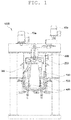
- an ultra-dispersion mixer 1000 may include a chamber 100, a blade drum 200, a low-speed blade 300, a high-speed blade 400, and an opening and closing device 500.
- the components will be described below in detail.
- the chamber 100 may have a space formed therein and may accommodate a mixed material, that is, powders and a binder solution for preparing a secondary battery slurry.
- the chamber 100 may stir the powders and the binder solutions to form a slurry for an electrode of a secondary battery, and in some embodiments, the completely stirred slurry for an electrode of a secondary battery may be discharged by opening and closing an upper or lower portion of the chamber 100 through the opening and closing device 500 or may be moved to the outside through a discharger formed on the chamber 100 and connected to the outside.
- the blade drum 200 may be disposed in an upper portion of an internal side of the chamber 100 and may perform a function of distributing at least one power transferred from the outside of the ultra-dispersion mixer 1000 to the low-speed blade 300 and the high-speed blade 400 and may perform a function of rotating in the upper portion of the internal side of the chamber 100 for an operation of the low-speed blade 300 connected to the blade drum 200.
- the low-speed blade 300 may stir the mixed material agglomerated on an internal wall of the chamber 100 to the center of the chamber 100.
- the low-speed blade 300 may have one end connected to at least one region of the blade drum 200 and the other end that extends along the internal wall of the chamber 100.
- the low-speed blade 300 may be disposed adjacent to the internal wall of the chamber 100 and may be disposed to prevent from interfering with the chamber 100 while the blade drum 200 rotates.
- the low-speed blade 300 may rotate inside the chamber 100 along with rotation of the blade drum 200, and thus may have the shape for improving the stirring efficiency together with the high-speed blade 400 disposed at the blade drum 200 and the shape and arrangement for preventing from interfering with the high-speed blade 400.
- a detailed description of the aforementioned shape of the low-speed blade 300 and the arrangement of the low-speed blade 300 for preventing from interfering with the high-speed blade 400 will be given with reference to FIG. 2 .
- the high-speed blade 400 may be disposed on the blade drum 200 and may shaft-rotate at high speed, and thereby may stir the mixed material accommodated in the chamber 100 to supply dispersion force to agglomerated particles of the accommodated mixed material and to tear each particle using a plurality of blade parts having different stirring characteristics and arranged on one shaft of the high-speed blade 400.
- a detailed description of the blade parts having different stirring characteristics and an arrangement method of the high-speed blade 400 will be given below with reference to FIGs. 2 and 3 .
- the opening and closing device 500 may be disposed at opposite sides of the chamber 100 and may perform a function of rotating the chamber 100 and a function of raising and lowering the chamber 100 on a support on which the chamber 100 is disposed.
- a power distributor 600 for distributing one or more powers transferred from a plurality of power sources 10a 10b may be insertion-installed to penetrate the upper portion of the chamber 100 and the center of the blade drum 200 to allow the blade drum 200 to rotate inside the chamber 100 of the ultra-dispersion mixer 1000 according to the present disclosure.
- the low-speed blade 300 and the high-speed blade 400 that are disposed at the blade drum 200 will be described in detail below.
- the low-speed blade 300 may have one end connected to a lower surface of the blade drum 200 and the other end that extends along the internal wall of the chamber 100 and may rotate along the internal wall of the chamber 100 together with the blade drum 200.
- the low-speed blade 300 may include a rod portion 310, a bottom portion 320, and a protrusion 330.
- the rod portion 310 may extend along the internal wall of the chamber 100 from the blade drum 200 and may stir the mixed material agglomerated on the internal wall of the chamber 100 to the center of the chamber 100.
- the bottom portion 320 may extend along a bottom surface of the chamber 100 from an end of the rod portion 310 and may stir the mixed material agglomerated on the bottom surface of the chamber.
- the protrusion 330 may protrude in a direction towards an internal side of the chamber 100 from the rod portion 310 and may perform a function of evenly transferring the mixed material oriented toward the high-speed blade 400 in the chamber 100 to the high-speed blade 400.
- the high-speed blade 400 may be arranged at a plurality of positions on the blade drum 200, in which case at least one high-speed blade may be arranged before and behind the low-speed blade 300.
- the high-speed blade 400 may be arranged in a region to prevent a plurality of blade parts having different stirring characteristics arranged on the high-speed blade 400 from interfering with the low-speed blade 300 during shaft rotation.
- the blade parts arranged on the high-speed blade 400 may be disposed between the protrusions 330 and may evenly supply the mixed material towards the high-speed blade 400 through rotation of the blade drum 200.
- blade parts may be arranged on the high-speed blade 400 of the ultra-dispersion mixer 1000 according to the present disclosure, and the blade parts will be described with reference to FIG. 3A .
- the high-speed blade 400 may use together a saw blade 410 and a star blade 420 having different stirring characteristics.
- the saw blade 410 may stir and tear powder agglomerates formed while the powders and the binder solution are mixed in the chamber 100
- the star blade 420 may stir the overall mixed material inside the chamber 100 in order to prevent the mixed material inside the chamber 100 from being fixed.
- FIG. 3 the high-speed blade 400 may use together a saw blade 410 and a star blade 420 having different stirring characteristics.
- the saw blade 410 may stir and tear powder agglomerates formed while the powders and the binder solution are mixed in the chamber 100
- the star blade 420 may stir the overall mixed material inside the chamber 100 in order to prevent the mixed material inside the chamber 100 from being fixed.
- the saw blade 410 may have saw blade parts 411 formed on an end of a circular plate and may supply dispersion force to tear a particle of the mixed material or the powder agglomerates inside the chamber 100.
- the star blade 420 may have rods 421 formed at ends of bodies that are formed like a circular plate or are radially arranged and may supply dispersion force to mix the overall mixed material flowing inside the chamber 100.
- the saw blade 410 and the star blade 420 may have other shapes for achieving the same effect as the shapes shown in FIGs. 3A and 3B .
- the ultra-dispersion mixer 1000 may distribute a plurality of powers transferred from the outside to the low-speed blade 300 and the high-speed blade 400 through the power distributor 600 insertion-installed into the blade drum 200.
- the power distributor 600 insertion-installed into the blade drum 200.
- the power distributor 600 may be insertion-installed to penetrate the upper portion of the chamber 100 and the center of the blade drum 200 and may distribute a plurality of powers transferred from the outside to the blade drum 200 or the high-speed blade 400.
- the power distributor 600 may include a first distributor 610 and a second distributor 620.
- the first distributor 610 may be formed with a hollow center and may distribute any one of a plurality of supplied powers to the blade drum.
- the second distributor 620 may be formed as a rotation shaft penetrating the center of the first distributor 610 and may distribute the other power of the supplied powers to one or more high-speed blades 400.
- the ultra-dispersion mixer 1000 may include a high-shear disperser 700.
- the configuration of the ultra-dispersion mixer 1000 including the high-shear disperser 700 will be described.
- the high-shear disperser 700 may stir the mixed material introduced from the chamber 100 by supplying high-shear dispersion force to the mixed material using rotation force of an impeller included therein and supplying shear force to particles of the mixed material, which are not dispersed in the low-speed blade 300 and the high-speed blade 400. Accordingly, an inlet and an outlet through which the mixed material flows may be formed in a lower portion of the chamber 100, and thus a predetermined amount of the mixed material stirred in the chamber 100 may be stirred in the high-shear disperser 700 and may then circulate again in the chamber 100, thereby rapidly producing a high-quality slurry for a secondary battery.
- a timing valve may be disposed at the inlet and the outlet to which the high-shear disperser 700 and the chamber 100 are connected and may also control supply of the mixed material.
- the ultra-dispersion mixer 1000 may include a heat exchanger 800 to adjust the temperature of a solution supplied thereto.
- a heat exchanger 800 to adjust the temperature of a solution supplied thereto.
- the heat exchanger 800 may perform a function of controlling the temperature of the solution supplied to the chamber 100.
- the mixed material including the powders and solution supplied to the chamber 100 may be agglomerated rather than being rapidly stirred due to high viscosity and low temperature at the beginning of stirring, and thus the heat exchanger 800 may be operated to increase the temperature of the solution until stirring inside the chamber 100 is continuously performed for a predetermined time and the mixed material is maintained at a temperature equal to or greater than a predetermined temperature for easy stirring.
- the ultra-dispersion mixer 1000 may further include the high-shear disperser 700 and the heat exchanger 800 other than the components of the chamber 100 in which the mixed material is stirred, and a high-quality slurry for an electrode of a secondary battery may be prepared by rapidly stirring the mixed material, and to this end, valves V1, V2, V3, and V4 may be arranged on flow channels of the high-shear disperser 700 and the heat exchanger 800 which are connected to the chamber 100 to control a feed rate.
- the ultra-dispersion mixer 1000 may further include a powder feeder 20 configured to supply powders to the chamber 100, a solution feeder 30 configured to supply a solution to the chamber 100, and the heat exchanger 800 configured to adjust a temperature of the solution supplied to the solution feeder 30.
- the ultra-dispersion mixer may change a stirring environment inside the mixer depending on the type of a material supplied to the mixer and a stirring degree of a mixed material during a procedure of preparing a slurry for a secondary battery, and accordingly the mixed material may be stirred to prepare the slurry for a secondary battery having high dispersion, thereby producing a high-quality slurry for a secondary battery for reducing the preparing costs and stirring time.
- Exemplary embodiments of the present disclosure can be variously changed and embodied in various forms, in which illustrative embodiments of the present disclosure are shown. However, exemplary embodiments of the present disclosure should not be construed as being limited to the embodiments set forth herein and any changes, equivalents, or alternatives which are within the spirit and scope of the present disclosure should be understood as falling within the scope of the present disclosure.
Landscapes
- Chemical & Material Sciences (AREA)
- Chemical Kinetics & Catalysis (AREA)
- Engineering & Computer Science (AREA)
- Manufacturing & Machinery (AREA)
- Electrochemistry (AREA)
- General Chemical & Material Sciences (AREA)
- Dispersion Chemistry (AREA)
- Aviation & Aerospace Engineering (AREA)
- Battery Electrode And Active Subsutance (AREA)
- Mixers Of The Rotary Stirring Type (AREA)
Abstract
Description
- This application claims priority under 35 U.S.C. §119 to Korean Patent Application No.
10-2020-0051937, filed on April 29, 2020 - The following disclosure relates to an ultra-dispersion mixer, and more particularly to an ultra-dispersion mixer for realizing various stirring characteristics in one mixer device to easily and effectively disperse elements of a slurry for a secondary battery, supplied into a mixer during a procedure of preparing the slurry of a secondary battery produced by performing mixing procedures multiple times.
- A slurry for a secondary battery is configured by mixing powders included in a positive electrode or a negative electrode, an adhesive (hereinafter, a binder) for fixing the powders to an electrode plate, a conductive agent for improving the electrical conductivity between the powders, and so on. When the slurry for a secondary battery is prepared, the powder, the binder powder, the conductive agent powder, and a binder solution may be put and stirred at one time, but in this case it is very difficult to stir the elements in a mixer due to aggregation, electrostatic attraction, and so on of each unit element and it is difficult to produce a slurry for a secondary battery having high marketability. Accordingly, in general, a slurry for a secondary battery is prepared by preparing a solution in advance by melting binder powders in a specific solvent, adding a positive electrode material, a negative electrode material powder, or the like to the prepared binder solution, and then stirring the resulting material. Here, when the binder solution is prepared, different binder solutions are used for a positive electrode and a negative electrode, respectively. In general, it is easy, in terms of the time and cost for preparing the slurry for a secondary battery, to sequentially perform mixing for preparing a binder solution and subsequent mixing for preparing the slurry for a secondary battery in a single mixing device. A conventional mixer device for preparing a slurry for a secondary battery is used to prepare the slurry for a secondary battery using a method of improving the dispersion of mixed materials by positioning a high-speed stirring body and a low-speed stirring body in a mixer, as disclosed in Korean Patent Publication No.
10-1737756 - 1.
KR 10-1737756 B1 (May 13, 2017 - An embodiment of the present disclosure is directed to providing an ultra-dispersion mixer for preparing a slurry for a secondary battery having high dispersion by realizing required stirring characteristics in one mixer depending on the powder and solution input during a procedure of preparing the slurry for a secondary battery, and increasing a feed rate of the slurry for a secondary battery by reducing the stirring time.
- In one general aspect, an ultra-dispersion mixer includes a chamber configured to accommodate a mixed material therein, a blade drum formed as a cylinder having a space formed therein and disposed to rotate at an upper portion of an internal side of the chamber, a low-speed blade having one end connected to a lower surface of the blade drum and a remaining end that extends along an internal wall of the chamber and rotates together with the blade drum along the internal wall of the chamber, and at least one high-speed blade having one end connected to the blade drum and a remaining end that extends towards an internal side of the chamber and rotating on the blade drum, wherein the high-speed blade has a plurality of blade parts having different stirring characteristics and arranged on one shaft.
- Here, the blades may include a saw blade that has a sawtooth protruding outside a circular plate and rotates, and a star blade that has a plurality of rods vertically extending outside a circular plate and rotates.
- Here, the low-speed blade may include a rod portion extending along an internal surface of the chamber, a bottom portion extending along a bottom surface of the chamber, and a plurality of protrusions that protrude towards the internal side of the chamber from the rod portion and are spaced apart from each other, wherein the blade parts may be arranged between the plurality of protrusions that are spaced apart from each other.
- Here, the ultra-dispersion mixer may further include a power distributor insertion-installed to penetrate an upper portion of the chamber and a center of the blade drum and configured to distribute one or more powers transferred from a plurality of power sources to the blade drum or the high-speed blade, wherein the power distributor may include a first distributor configured to distribute any one of powers transferred from the plurality of power sources to the blade drum, and a second distributor formed as a rotation shaft penetrating a center of the first distributor and configured to distribute remaining power of the powers transferred from the plurality of power sources to the high-speed blade, and the low-speed blade may rotate together with the blade drum, and the high-speed blade may rotate on the blade drum.
- Furthermore, the high-speed blade may rotate at a higher speed than a revolution speed of the low-speed blade.
- Here, the ultra-dispersion mixer may further include an opening and closing device connected to opposite sides of the chamber and configured to raise and lower the chamber on a support on which the chamber is disposed.
- Here, the ultra-dispersion mixer may further include a powder feeder configured to supply powders to the chamber, a solution feeder configured to supply a solution to the chamber, and a heat exchanger configured to adjust a temperature of the solution supplied to the solution feeder.
- Here, the ultra-dispersion mixer may further include a high-shear disperser configured to supply high-shear dispersion force to a mixed material introduced from the chamber using rotation force of an impeller included in the ultra-dispersion mixer, wherein an inlet and an outlet that are formed in a lower portion of the chamber may be connected to the high-shear disperser.
- In this case, the inlet and the outlet may include timing valves formed thereon, which are opened and closed after the mixed material is stirred in the chamber during a user set time or greater.
-
-
FIG. 1 is a diagram showing an ultra-dispersion mixer according to the present disclosure. -
FIG. 2 is a diagram showing a high-speed blade of an ultra-dispersion mixer according to the present disclosure. -
FIG. 3 is a diagram showing blade parts of an ultra-dispersion mixer according to the present disclosure. -
FIG. 4 is a diagram showing a blade drum of an ultra-dispersion mixer according to the present disclosure. -
FIG. 5 is a diagram showing an ultra-dispersion mixer according to an embodiment of the present disclosure. -
FIG. 6 is a diagram showing an ultra-dispersion mixer according to another embodiment of the present disclosure. - Hereinafter, the present disclosure will be described in detail through explaining exemplary embodiments of the present disclosure with reference to the accompanying drawings.
- The accompanying drawings illustrate merely an example for more clearly understanding the features of the present disclosure and thus the features of the present disclosure should not be limited by the accompanying drawings.
- As shown in
FIG. 1 , anultra-dispersion mixer 1000 according to the present disclosure may include achamber 100, ablade drum 200, a low-speed blade 300, a high-speed blade 400, and an opening andclosing device 500. The components will be described below in detail. - The
chamber 100 may have a space formed therein and may accommodate a mixed material, that is, powders and a binder solution for preparing a secondary battery slurry. Thechamber 100 may stir the powders and the binder solutions to form a slurry for an electrode of a secondary battery, and in some embodiments, the completely stirred slurry for an electrode of a secondary battery may be discharged by opening and closing an upper or lower portion of thechamber 100 through the opening andclosing device 500 or may be moved to the outside through a discharger formed on thechamber 100 and connected to the outside. - The
blade drum 200 may be disposed in an upper portion of an internal side of thechamber 100 and may perform a function of distributing at least one power transferred from the outside of theultra-dispersion mixer 1000 to the low-speed blade 300 and the high-speed blade 400 and may perform a function of rotating in the upper portion of the internal side of thechamber 100 for an operation of the low-speed blade 300 connected to theblade drum 200. - The low-
speed blade 300 may stir the mixed material agglomerated on an internal wall of thechamber 100 to the center of thechamber 100. The low-speed blade 300 may have one end connected to at least one region of theblade drum 200 and the other end that extends along the internal wall of thechamber 100. Thus, the low-speed blade 300 may be disposed adjacent to the internal wall of thechamber 100 and may be disposed to prevent from interfering with thechamber 100 while theblade drum 200 rotates. Furthermore, the low-speed blade 300 may rotate inside thechamber 100 along with rotation of theblade drum 200, and thus may have the shape for improving the stirring efficiency together with the high-speed blade 400 disposed at theblade drum 200 and the shape and arrangement for preventing from interfering with the high-speed blade 400. A detailed description of the aforementioned shape of the low-speed blade 300 and the arrangement of the low-speed blade 300 for preventing from interfering with the high-speed blade 400 will be given with reference toFIG. 2 . - The high-
speed blade 400 may be disposed on theblade drum 200 and may shaft-rotate at high speed, and thereby may stir the mixed material accommodated in thechamber 100 to supply dispersion force to agglomerated particles of the accommodated mixed material and to tear each particle using a plurality of blade parts having different stirring characteristics and arranged on one shaft of the high-speed blade 400. A detailed description of the blade parts having different stirring characteristics and an arrangement method of the high-speed blade 400 will be given below with reference toFIGs. 2 and3 . - The opening and
closing device 500 may be disposed at opposite sides of thechamber 100 and may perform a function of rotating thechamber 100 and a function of raising and lowering thechamber 100 on a support on which thechamber 100 is disposed. - As shown in
FIG. 2 , apower distributor 600 for distributing one or more powers transferred from a plurality ofpower sources 10achamber 100 and the center of theblade drum 200 to allow theblade drum 200 to rotate inside thechamber 100 of theultra-dispersion mixer 1000 according to the present disclosure. In this case, the low-speed blade 300 and the high-speed blade 400 that are disposed at theblade drum 200 will be described in detail below. - The low-
speed blade 300 may have one end connected to a lower surface of theblade drum 200 and the other end that extends along the internal wall of thechamber 100 and may rotate along the internal wall of thechamber 100 together with theblade drum 200. In this case, the low-speed blade 300 may include arod portion 310, abottom portion 320, and aprotrusion 330. - The
rod portion 310 may extend along the internal wall of thechamber 100 from theblade drum 200 and may stir the mixed material agglomerated on the internal wall of thechamber 100 to the center of thechamber 100. - The
bottom portion 320 may extend along a bottom surface of thechamber 100 from an end of therod portion 310 and may stir the mixed material agglomerated on the bottom surface of the chamber. - As shown in
FIG. 2 , theprotrusion 330 may protrude in a direction towards an internal side of thechamber 100 from therod portion 310 and may perform a function of evenly transferring the mixed material oriented toward the high-speed blade 400 in thechamber 100 to the high-speed blade 400. - The high-
speed blade 400 may be arranged at a plurality of positions on theblade drum 200, in which case at least one high-speed blade may be arranged before and behind the low-speed blade 300. In this case, the high-speed blade 400 may be arranged in a region to prevent a plurality of blade parts having different stirring characteristics arranged on the high-speed blade 400 from interfering with the low-speed blade 300 during shaft rotation. Furthermore, the blade parts arranged on the high-speed blade 400 may be disposed between theprotrusions 330 and may evenly supply the mixed material towards the high-speed blade 400 through rotation of theblade drum 200. - As shown in
FIG. 3 , blade parts may be arranged on the high-speed blade 400 of theultra-dispersion mixer 1000 according to the present disclosure, and the blade parts will be described with reference toFIG. 3A . As shown inFIG. 3A , the high-speed blade 400 may use together asaw blade 410 and astar blade 420 having different stirring characteristics. Thus, thesaw blade 410 may stir and tear powder agglomerates formed while the powders and the binder solution are mixed in thechamber 100, and thestar blade 420 may stir the overall mixed material inside thechamber 100 in order to prevent the mixed material inside thechamber 100 from being fixed. As shown inFIG. 3B , thesaw blade 410 may have sawblade parts 411 formed on an end of a circular plate and may supply dispersion force to tear a particle of the mixed material or the powder agglomerates inside thechamber 100. Furthermore, thestar blade 420 may haverods 421 formed at ends of bodies that are formed like a circular plate or are radially arranged and may supply dispersion force to mix the overall mixed material flowing inside thechamber 100. Needless to say, thesaw blade 410 and thestar blade 420 may have other shapes for achieving the same effect as the shapes shown inFIGs. 3A and 3B . - As shown in
FIG. 4 , theultra-dispersion mixer 1000 according to the present disclosure may distribute a plurality of powers transferred from the outside to the low-speed blade 300 and the high-speed blade 400 through thepower distributor 600 insertion-installed into theblade drum 200. Hereinafter, a detailed shape of theblade drum 200 and a method of distributing power will be described. - The
power distributor 600 may be insertion-installed to penetrate the upper portion of thechamber 100 and the center of theblade drum 200 and may distribute a plurality of powers transferred from the outside to theblade drum 200 or the high-speed blade 400. In detail, thepower distributor 600 may include afirst distributor 610 and asecond distributor 620. Thefirst distributor 610 may be formed with a hollow center and may distribute any one of a plurality of supplied powers to the blade drum. Thesecond distributor 620 may be formed as a rotation shaft penetrating the center of thefirst distributor 610 and may distribute the other power of the supplied powers to one or more high-speed blades 400. - As shown in
FIG. 5 , theultra-dispersion mixer 1000 according to the present disclosure may include a high-shear disperser 700. Hereinafter, the configuration of theultra-dispersion mixer 1000 including the high-shear disperser 700 will be described. - The high-
shear disperser 700 may stir the mixed material introduced from thechamber 100 by supplying high-shear dispersion force to the mixed material using rotation force of an impeller included therein and supplying shear force to particles of the mixed material, which are not dispersed in the low-speed blade 300 and the high-speed blade 400. Accordingly, an inlet and an outlet through which the mixed material flows may be formed in a lower portion of thechamber 100, and thus a predetermined amount of the mixed material stirred in thechamber 100 may be stirred in the high-shear disperser 700 and may then circulate again in thechamber 100, thereby rapidly producing a high-quality slurry for a secondary battery. Furthermore, at the beginning of stirring in which a powder and a solution are mixed as a mixed material, it may be difficult to operate the high-shear disperser 700 due to the powder agglomerates, and accordingly the mixed material inside thechamber 100 may achieve dispersion within a range for operating the high-shear disperser 700 and may then circulate in thechamber 100 and the high-shear disperser 700, thereby preparing a slurry for a secondary battery having high dispersion. In addition, a timing valve may be disposed at the inlet and the outlet to which the high-shear disperser 700 and thechamber 100 are connected and may also control supply of the mixed material. - As shown in
FIG. 6 , theultra-dispersion mixer 1000 according to the present disclosure may include aheat exchanger 800 to adjust the temperature of a solution supplied thereto. Hereinafter, the configuration of theultra-dispersion mixer 1000 including theheat exchanger 800 will be described. - The
heat exchanger 800 may perform a function of controlling the temperature of the solution supplied to thechamber 100. In detail, the mixed material including the powders and solution supplied to thechamber 100 may be agglomerated rather than being rapidly stirred due to high viscosity and low temperature at the beginning of stirring, and thus theheat exchanger 800 may be operated to increase the temperature of the solution until stirring inside thechamber 100 is continuously performed for a predetermined time and the mixed material is maintained at a temperature equal to or greater than a predetermined temperature for easy stirring. - As shown in
FIGs. 5 and6 , according to an embodiment, theultra-dispersion mixer 1000 according to the present disclosure may further include the high-shear disperser 700 and theheat exchanger 800 other than the components of thechamber 100 in which the mixed material is stirred, and a high-quality slurry for an electrode of a secondary battery may be prepared by rapidly stirring the mixed material, and to this end, valves V1, V2, V3, and V4 may be arranged on flow channels of the high-shear disperser 700 and theheat exchanger 800 which are connected to thechamber 100 to control a feed rate. - The
ultra-dispersion mixer 1000 may further include a powder feeder 20 configured to supply powders to thechamber 100, asolution feeder 30 configured to supply a solution to thechamber 100, and theheat exchanger 800 configured to adjust a temperature of the solution supplied to thesolution feeder 30. - Since the ultra-dispersion mixer according to the present disclosure as configured above includes a plurality of stirring devices having various stirring characteristics, the ultra-dispersion mixer may change a stirring environment inside the mixer depending on the type of a material supplied to the mixer and a stirring degree of a mixed material during a procedure of preparing a slurry for a secondary battery, and accordingly the mixed material may be stirred to prepare the slurry for a secondary battery having high dispersion, thereby producing a high-quality slurry for a secondary battery for reducing the preparing costs and stirring time.
- Exemplary embodiments of the present disclosure can be variously changed and embodied in various forms, in which illustrative embodiments of the present disclosure are shown. However, exemplary embodiments of the present disclosure should not be construed as being limited to the embodiments set forth herein and any changes, equivalents, or alternatives which are within the spirit and scope of the present disclosure should be understood as falling within the scope of the present disclosure.
- It will be understood that when an element is referred to as being "connected to", or "coupled to" another element, it may be directly o 0n, connected to, or coupled to the other element, or intervening elements may be present.
- Unless otherwise defined, all terms including technical and scientific terms used herein have the same meaning as commonly understood by one of ordinary skill in the art to which this present disclosure belongs.
- It will be further understood that terms, such as those defined in commonly used dictionaries, should be interpreted as having meanings that are consistent with their meanings in the context of the relevant art and will not be interpreted in an idealized or overly formal sense unless expressly so defined herein.
- It will be understood by those of ordinary skill in the art that the present disclosure is not limited to the above embodiments and various changes in form and details may be made therein without departing from the spirit and scope of the present disclosure as defined by the following claims.
Claims (9)
- An ultra-dispersion mixer comprising:a chamber configured to accommodate a mixed material therein;a blade drum formed as a cylinder having a space formed therein and disposed to rotate at an upper portion of an internal side of the chamber;a low-speed blade having one end connected to a lower surface of the blade drum and a remaining end that extends along an internal wall of the chamber and rotates together with the blade drum along the internal wall of the chamber; andat least one high-speed blade having one end connected to the blade drum and a remaining end that extends towards an internal side of the chamber and rotating on the blade drum,wherein the high-speed blade has a plurality of blade parts having different stirring characteristics and arranged on one shaft.
- The ultra-dispersion mixer of claim 1, wherein the blade parts include:a saw blade that has a sawtooth protruding outside a circular plate and rotates; anda star blade that has a plurality of rods vertically extending outside a circular plate and rotates.
- The ultra-dispersion mixer of claim 1, wherein the low-speed blade includes:a rod portion extending along an internal surface of the chamber;a bottom portion extending along a bottom surface of the chamber; anda plurality of protrusions that protrude towards the internal side of the chamber from the rod portion and are spaced apart from each other,wherein the blade parts are arranged between the plurality of protrusions that are spaced apart from each other.
- The ultra-dispersion mixer of claim 1, further comprising:a power distributor insertion-installed to penetrate an upper portion of the chamber and a center of the blade drum and configured to distribute one or more powers transferred from a plurality of power sources to the blade drum or the high-speed blade,wherein the power distributor includes a first distributor configured to distribute any one of powers transferred from the plurality of power sources to the blade drum, and a second distributor formed as a rotation shaft penetrating a center of the first distributor and configured to distribute remaining power of the powers transferred from the plurality of power sources to the high-speed blade, andwherein the low-speed blade rotates together with the blade drum, and the high-speed blade rotates on the blade drum.
- The ultra-dispersion mixer of claim 3, wherein the high-speed blade rotates at a higher speed than a revolution speed of the low-speed blade.
- The ultra-dispersion mixer of claim 1, further comprising:
an opening and closing device is disposed at opposite sides of the chamber to rotate the chamber and raise and lower the chamber on a support on which the chamber is disposed. - The ultra-dispersion mixer of claim 1, further comprising:a powder feeder configured to supply powders to the chamber;a solution feeder configured to supply a solution to the chamber; anda heat exchanger configured to adjust a temperature of the solution supplied to the solution feeder.
- The ultra-dispersion mixer of claim 1, further comprising:a high-shear disperser configured to supply high-shear dispersion force to a mixed material introduced from the chamber using rotation force of an impeller included in the ultra-dispersion mixer,wherein an inlet and an outlet that are formed in a lower portion of the chamber are connected to the high-shear disperser.
- The ultra-dispersion mixer of claim 8, wherein the inlet and the outlet include timing valves formed thereon, which are opened and closed after the mixed material is stirred in the chamber during a user set time or greater.
Applications Claiming Priority (1)
| Application Number | Priority Date | Filing Date | Title |
|---|---|---|---|
| KR1020200051937A KR102611670B1 (en) | 2020-04-29 | 2020-04-29 | Ultra Dispersion Mixer |
Publications (2)
| Publication Number | Publication Date |
|---|---|
| EP3903917A1 true EP3903917A1 (en) | 2021-11-03 |
| EP3903917B1 EP3903917B1 (en) | 2024-10-30 |
Family
ID=75728756
Family Applications (1)
| Application Number | Title | Priority Date | Filing Date |
|---|---|---|---|
| EP21171014.0A Active EP3903917B1 (en) | 2020-04-29 | 2021-04-28 | Ultra-dispersion mixer |
Country Status (7)
| Country | Link |
|---|---|
| US (2) | US12064734B2 (en) |
| EP (1) | EP3903917B1 (en) |
| KR (2) | KR102611670B1 (en) |
| CN (2) | CN113559735B (en) |
| DE (1) | DE202021004475U1 (en) |
| HU (1) | HUE069453T2 (en) |
| PL (1) | PL3903917T3 (en) |
Cited By (1)
| Publication number | Priority date | Publication date | Assignee | Title |
|---|---|---|---|---|
| CN120515324A (en) * | 2025-07-22 | 2025-08-22 | 泉州市康艺食品饮料有限公司 | A candy slurry mixer with layered temperature control |
Families Citing this family (9)
| Publication number | Priority date | Publication date | Assignee | Title |
|---|---|---|---|---|
| CN114377570A (en) * | 2022-01-28 | 2022-04-22 | 罗斯(无锡)设备有限公司 | A large dispersing disk arrangement structure |
| KR102610699B1 (en) | 2022-02-18 | 2023-12-06 | 에스케이온 주식회사 | Vacuum type powder transfer system and method thereof |
| EP4309773A4 (en) | 2022-06-08 | 2024-07-24 | Contemporary Amperex Technology Co., Limited | MIXED DISPERSION DEVICE |
| CN217068455U (en) * | 2022-06-08 | 2022-07-29 | 宁德时代新能源科技股份有限公司 | Mixing and dispersing device |
| KR102618810B1 (en) * | 2022-11-17 | 2023-12-28 | (주)티에스아이 | Slurry mixer |
| CN116617893A (en) * | 2023-05-27 | 2023-08-22 | 江西恒力电池科技有限公司 | A slurry additive mixing equipment for storage battery production |
| CN117065616B (en) * | 2023-09-13 | 2024-11-12 | 林郁君 | A homogenization system based on lithium battery slurry production |
| CN118718811B (en) * | 2024-09-04 | 2024-11-22 | 连云港联润新材料有限公司 | Special material mixing proportioning device of electron |
| CN119455741B (en) * | 2025-01-16 | 2025-04-08 | 山东隆信药业有限公司 | Emulsification device is used in salicylic acid preparation |
Citations (6)
| Publication number | Priority date | Publication date | Assignee | Title |
|---|---|---|---|---|
| DE2318949B1 (en) * | 1973-04-14 | 1974-10-17 | Kalle Ag, 6202 Wiesbaden-Biebrich | Combined mixing and homogenizing machine |
| GB2158727A (en) * | 1984-05-03 | 1985-11-20 | Chem Plant Stainless Ltd | Mixing apparatus |
| JPS641730U (en) * | 1987-06-23 | 1989-01-06 | ||
| DE9110133U1 (en) * | 1991-08-16 | 1991-09-26 | Rütgerswerke AG, 6000 Frankfurt | Stirred reactor |
| CN201470388U (en) * | 2009-08-14 | 2010-05-19 | 南京科思化学有限公司 | Reaction vessel with jacket |
| KR101737756B1 (en) | 2017-01-20 | 2017-05-18 | (주)티에스아이 | Slurry Mixer for Battery Electrode |
Family Cites Families (41)
| Publication number | Priority date | Publication date | Assignee | Title |
|---|---|---|---|---|
| FR2097243A5 (en) * | 1970-06-12 | 1972-03-03 | Olsa Sarl | Blending mixer - with bladed stirrer having an emulsifier - turbine at its inner zone |
| DE2757486A1 (en) * | 1977-12-22 | 1979-07-05 | Draiswerke Gmbh | DEVICE FOR DISCONTINUOUS MIXING OF AT LEAST TWO SUBSTANCES |
| US4380398A (en) * | 1980-09-16 | 1983-04-19 | Burgess Basil A | Dispersion mixer |
| US4854720A (en) * | 1983-07-15 | 1989-08-08 | Schold George R | Disperser apparatus with two coaxial drive shafts |
| US5102229A (en) * | 1990-06-15 | 1992-04-07 | Sumitomo Heavy Industries, Ltd | Agitator |
| JP3494702B2 (en) * | 1994-07-15 | 2004-02-09 | 吉野石膏株式会社 | Mixing stirrer and mixing stirring method |
| DE29805360U1 (en) * | 1998-03-25 | 1998-05-28 | Stahl, Walter, 67361 Freisbach | mixer |
| US6021707A (en) * | 1998-04-27 | 2000-02-08 | Bauer; William A. | Safety means for tilting kettle |
| US20040234677A1 (en) * | 1999-08-12 | 2004-11-25 | Nisshinbo Industries, Inc. | Mixer for coating an ion-conducting polymer on a powdered substance and method for coating the same |
| SE0000522D0 (en) * | 2000-02-17 | 2000-02-17 | Astrazeneca Ab | Mixing apparatus |
| JP4456221B2 (en) | 2000-03-17 | 2010-04-28 | 株式会社井上製作所 | Concentric 2-axis mixer |
| ATE400356T1 (en) * | 2005-02-09 | 2008-07-15 | Shinagawa Machinery Works Co L | KNEADING AND GRANULATING MACHINE |
| KR200406596Y1 (en) | 2005-11-01 | 2006-01-23 | (주)세종기술 | Stirring Tank Structure of Chemical Stirrer |
| KR100873414B1 (en) * | 2007-06-27 | 2008-12-11 | (주)나라기술 | Agitator |
| DE102008045820A1 (en) * | 2008-09-05 | 2010-04-08 | Axel Wittek | Transition elements for passing a dispersion in the treatment in a rotor-stator dispersing machine |
| KR200451440Y1 (en) | 2010-07-27 | 2010-12-15 | 주식회사 지노믹코리아 | Solution Stirrer with Improved Cleaning and Stirring |
| JP2011147936A (en) | 2010-09-29 | 2011-08-04 | Sintokogio Ltd | Shearing type dispersing device, circulation type dispersing system and circulation type dispersing method |
| CN102451638A (en) * | 2010-10-22 | 2012-05-16 | 上海图盛投资咨询有限公司 | System for homogenizing battery slurry efficiently |
| US8979356B2 (en) * | 2012-12-18 | 2015-03-17 | Feldmeier Equipment, Inc. | Dual agitator mixer with sanitary tank |
| KR101283910B1 (en) * | 2013-04-11 | 2013-07-16 | 주식회사 젠닥스 | Apparatus for stirring and grinding |
| CN103263960B (en) * | 2013-05-14 | 2015-12-16 | 苏州工业园区日高能源科技有限公司 | A kind of slurry apparatus for grinding and dispersing and method thereof |
| JP2015037009A (en) | 2013-08-12 | 2015-02-23 | 株式会社イズミフードマシナリ | Dispersion/mixture system with dispersion/mixture pump used for manufacturing slurry containing carbon |
| KR20150025684A (en) * | 2013-08-30 | 2015-03-11 | 주식회사 엘지화학 | Impeller mixer of electrode slurry |
| US9890284B2 (en) * | 2014-04-16 | 2018-02-13 | Xerox Corporation | Process and apparatus for preparing pigment and wax dual dispersions |
| CN104437212B (en) * | 2014-12-16 | 2016-09-07 | 江苏华东锂电技术研究院有限公司 | Cell size Preparation equipment |
| JP6609624B2 (en) * | 2015-03-31 | 2019-11-20 | 株式会社クボタ | Aggregation mixing device |
| CN206139111U (en) * | 2016-08-30 | 2017-05-03 | 乌鲁木齐市新荣得化工有限责任公司 | Polyurethane sealant planet stirring high speed dispersion discontinuous automated production machine |
| CN106654211A (en) * | 2016-12-22 | 2017-05-10 | 深圳拓邦股份有限公司 | Slurry for lithium-ion battery and preparation method of slurry |
| CN106732008A (en) * | 2017-02-22 | 2017-05-31 | 康福民 | A kind of high force dispersion machine |
| CN107308875A (en) * | 2017-08-02 | 2017-11-03 | 中银(宁波)电池有限公司 | Cell size ultrasonic wave mixing apparatus |
| KR101992949B1 (en) * | 2017-09-21 | 2019-06-26 | 주식회사 우원 | Raw material homogenization equipment with surface temperature sensor |
| CN208493994U (en) * | 2017-11-27 | 2019-02-15 | 佛山市宏瑞德新能源精密设备有限公司 | Mixing plant large area dispersed structure |
| KR101844921B1 (en) | 2017-11-28 | 2018-04-03 | 주식회사 윤성에프앤씨 | Mixer device for secondary cell |
| US11445741B2 (en) * | 2017-12-15 | 2022-09-20 | Societe Des Produits Nestle S.A. | Process for sugar modulation |
| WO2019130654A1 (en) * | 2017-12-26 | 2019-07-04 | 洋輝 中村 | Device for manufacturing suspension |
| CN208465752U (en) * | 2018-01-04 | 2019-02-05 | 安徽益佳通电池有限公司 | A battery slurry stirring device |
| KR102084225B1 (en) * | 2018-06-19 | 2020-03-05 | 주식회사 지에스나노셀 | Complex distribution system combining high shear dispersion and ultrasonic dispersion |
| CN209848803U (en) * | 2019-03-06 | 2019-12-27 | 中航锂电(洛阳)有限公司 | A lithium battery slurry dispersion equipment |
| KR101981131B1 (en) | 2019-03-15 | 2019-05-22 | (주)티에스아이 | Slurry Mixer for Battery Electrode |
| CN110681294B (en) | 2019-10-22 | 2020-08-18 | 淮北市普十新能源科技有限公司 | A mixing arrangement for lithium cell electricity core thick liquids |
| CN110773038A (en) * | 2019-12-02 | 2020-02-11 | 嘉善剑桥生物化工有限公司 | Compounding stirring subassembly |
-
2020
- 2020-04-29 KR KR1020200051937A patent/KR102611670B1/en active Active
-
2021
- 2021-04-15 CN CN202110405928.8A patent/CN113559735B/en active Active
- 2021-04-15 CN CN202411722656.4A patent/CN119386708A/en active Pending
- 2021-04-28 DE DE202021004475.2U patent/DE202021004475U1/en active Active
- 2021-04-28 PL PL21171014.0T patent/PL3903917T3/en unknown
- 2021-04-28 HU HUE21171014A patent/HUE069453T2/en unknown
- 2021-04-28 US US17/243,298 patent/US12064734B2/en active Active
- 2021-04-28 EP EP21171014.0A patent/EP3903917B1/en active Active
-
2023
- 2023-12-05 KR KR1020230173983A patent/KR102739492B1/en active Active
-
2024
- 2024-07-23 US US18/780,489 patent/US20240375068A1/en active Pending
Patent Citations (6)
| Publication number | Priority date | Publication date | Assignee | Title |
|---|---|---|---|---|
| DE2318949B1 (en) * | 1973-04-14 | 1974-10-17 | Kalle Ag, 6202 Wiesbaden-Biebrich | Combined mixing and homogenizing machine |
| GB2158727A (en) * | 1984-05-03 | 1985-11-20 | Chem Plant Stainless Ltd | Mixing apparatus |
| JPS641730U (en) * | 1987-06-23 | 1989-01-06 | ||
| DE9110133U1 (en) * | 1991-08-16 | 1991-09-26 | Rütgerswerke AG, 6000 Frankfurt | Stirred reactor |
| CN201470388U (en) * | 2009-08-14 | 2010-05-19 | 南京科思化学有限公司 | Reaction vessel with jacket |
| KR101737756B1 (en) | 2017-01-20 | 2017-05-18 | (주)티에스아이 | Slurry Mixer for Battery Electrode |
Cited By (1)
| Publication number | Priority date | Publication date | Assignee | Title |
|---|---|---|---|---|
| CN120515324A (en) * | 2025-07-22 | 2025-08-22 | 泉州市康艺食品饮料有限公司 | A candy slurry mixer with layered temperature control |
Also Published As
| Publication number | Publication date |
|---|---|
| DE202021004475U1 (en) | 2024-12-09 |
| US20210339210A1 (en) | 2021-11-04 |
| CN113559735B (en) | 2024-12-24 |
| EP3903917B1 (en) | 2024-10-30 |
| US12064734B2 (en) | 2024-08-20 |
| CN113559735A (en) | 2021-10-29 |
| US20240375068A1 (en) | 2024-11-14 |
| KR102739492B1 (en) | 2024-12-11 |
| PL3903917T3 (en) | 2025-03-31 |
| KR102611670B1 (en) | 2023-12-14 |
| HUE069453T2 (en) | 2025-03-28 |
| KR20240007095A (en) | 2024-01-16 |
| KR20210133400A (en) | 2021-11-08 |
| CN119386708A (en) | 2025-02-07 |
Similar Documents
| Publication | Publication Date | Title |
|---|---|---|
| US12064734B2 (en) | Ultra-dispersion mixer | |
| US10566602B2 (en) | Distribution and processing of battery electrode slurry and similar suspensions | |
| KR101844921B1 (en) | Mixer device for secondary cell | |
| KR101856482B1 (en) | High shear mixer | |
| JP2005270955A (en) | Treatment apparatus and powder treatment method | |
| CN107138070B (en) | A dual-rotor homogenization and dispersion device for solid-liquid mixed phase | |
| KR20120135033A (en) | Dispersion method and dispersion system | |
| JP6291903B2 (en) | Kneading equipment | |
| CN114345163A (en) | A three-paddle type mixing and stirring equipment for battery slurry stirring | |
| WO2024008095A1 (en) | Slurry preparation device and solid-liquid mixing apparatus | |
| JP2016163853A (en) | Preliminary kneader and kneader | |
| US20240382914A1 (en) | Stirring device | |
| JP2015174015A (en) | Powder agitation method | |
| CN219722535U (en) | Homogenization device, homogenization system and battery production line | |
| US12508600B2 (en) | Horizontal bead mill for dispersing secondary battery material, and conductive material dispersion method | |
| CN115090137B (en) | Pulp making equipment, pulping systems and battery production systems | |
| CN221763925U (en) | A powder flow cooling device capable of achieving uniform feeding | |
| CN104441387A (en) | Auxiliary material input device of foaming machine | |
| US20250229241A1 (en) | Stirring Device with Cooling Function | |
| CN121669067A (en) | Dispersing double-planetary stirrer and homogenizing method | |
| CN212091940U (en) | Powder mixer | |
| JP4848192B2 (en) | Sodium dispersion production method and sodium dispersion produced by the sodium dispersion production method | |
| EP4563218A1 (en) | Pulp preparing device and high-speed pulping machine | |
| CN121972049A (en) | Powder processing equipment and dry mixing method | |
| CN109384635A (en) | A kind of continuous mixing device of emulsion |
Legal Events
| Date | Code | Title | Description |
|---|---|---|---|
| REG | Reference to a national code |
Ref country code: DE Ref legal event code: R138 Ref document number: 202021004475 Country of ref document: DE Free format text: GERMAN DOCUMENT NUMBER IS 602021020866 |
|
| PUAI | Public reference made under article 153(3) epc to a published international application that has entered the european phase |
Free format text: ORIGINAL CODE: 0009012 |
|
| STAA | Information on the status of an ep patent application or granted ep patent |
Free format text: STATUS: REQUEST FOR EXAMINATION WAS MADE |
|
| 17P | Request for examination filed |
Effective date: 20210428 |
|
| AK | Designated contracting states |
Kind code of ref document: A1 Designated state(s): AL AT BE BG CH CY CZ DE DK EE ES FI FR GB GR HR HU IE IS IT LI LT LU LV MC MK MT NL NO PL PT RO RS SE SI SK SM TR |
|
| B565 | Issuance of search results under rule 164(2) epc |
Effective date: 20210927 |
|
| RAP3 | Party data changed (applicant data changed or rights of an application transferred) |
Owner name: YUNSUNG F&C CO., LTD Owner name: SK INNOVATION CO., LTD. |
|
| STAA | Information on the status of an ep patent application or granted ep patent |
Free format text: STATUS: EXAMINATION IS IN PROGRESS |
|
| RAP1 | Party data changed (applicant data changed or rights of an application transferred) |
Owner name: YUNSUNG F&C CO., LTD Owner name: SK ON CO., LTD. |
|
| 17Q | First examination report despatched |
Effective date: 20230208 |
|
| P01 | Opt-out of the competence of the unified patent court (upc) registered |
Effective date: 20230603 |
|
| REG | Reference to a national code |
Ref legal event code: R079 Free format text: PREVIOUS MAIN CLASS: B01F0003120000 Ref country code: DE Ref legal event code: R079 Ref document number: 602021020866 Country of ref document: DE Free format text: PREVIOUS MAIN CLASS: B01F0003120000 Ipc: B01F0023530000 |
|
| GRAP | Despatch of communication of intention to grant a patent |
Free format text: ORIGINAL CODE: EPIDOSNIGR1 |
|
| STAA | Information on the status of an ep patent application or granted ep patent |
Free format text: STATUS: GRANT OF PATENT IS INTENDED |
|
| RIC1 | Information provided on ipc code assigned before grant |
Ipc: B01F 35/30 20220101ALI20240422BHEP Ipc: B01F 27/95 20220101ALI20240422BHEP Ipc: B01F 27/85 20220101ALI20240422BHEP Ipc: B01F 27/806 20220101ALI20240422BHEP Ipc: B01F 27/192 20220101ALI20240422BHEP Ipc: B01F 27/1152 20220101ALI20240422BHEP Ipc: B01F 27/1122 20220101ALI20240422BHEP Ipc: B01F 27/1121 20220101ALI20240422BHEP Ipc: B01F 27/072 20220101ALI20240422BHEP Ipc: B01F 23/53 20220101AFI20240422BHEP |
|
| INTG | Intention to grant announced |
Effective date: 20240528 |
|
| GRAS | Grant fee paid |
Free format text: ORIGINAL CODE: EPIDOSNIGR3 |
|
| GRAA | (expected) grant |
Free format text: ORIGINAL CODE: 0009210 |
|
| STAA | Information on the status of an ep patent application or granted ep patent |
Free format text: STATUS: THE PATENT HAS BEEN GRANTED |
|
| AK | Designated contracting states |
Kind code of ref document: B1 Designated state(s): AL AT BE BG CH CY CZ DE DK EE ES FI FR GB GR HR HU IE IS IT LI LT LU LV MC MK MT NL NO PL PT RO RS SE SI SK SM TR |
|
| REG | Reference to a national code |
Ref country code: GB Ref legal event code: FG4D |
|
| REG | Reference to a national code |
Ref country code: CH Ref legal event code: EP |
|
| REG | Reference to a national code |
Ref country code: DE Ref legal event code: R096 Ref document number: 602021020866 Country of ref document: DE |
|
| REG | Reference to a national code |
Ref country code: IE Ref legal event code: FG4D |
|
| REG | Reference to a national code |
Ref country code: LT Ref legal event code: MG9D |
|
| REG | Reference to a national code |
Ref country code: NL Ref legal event code: MP Effective date: 20241030 |
|
| REG | Reference to a national code |
Ref country code: HU Ref legal event code: AG4A Ref document number: E069453 Country of ref document: HU |
|
| PG25 | Lapsed in a contracting state [announced via postgrant information from national office to epo] |
Ref country code: PT Free format text: LAPSE BECAUSE OF FAILURE TO SUBMIT A TRANSLATION OF THE DESCRIPTION OR TO PAY THE FEE WITHIN THE PRESCRIBED TIME-LIMIT Effective date: 20250228 Ref country code: IS Free format text: LAPSE BECAUSE OF FAILURE TO SUBMIT A TRANSLATION OF THE DESCRIPTION OR TO PAY THE FEE WITHIN THE PRESCRIBED TIME-LIMIT Effective date: 20250228 Ref country code: HR Free format text: LAPSE BECAUSE OF FAILURE TO SUBMIT A TRANSLATION OF THE DESCRIPTION OR TO PAY THE FEE WITHIN THE PRESCRIBED TIME-LIMIT Effective date: 20241030 |
|
| PG25 | Lapsed in a contracting state [announced via postgrant information from national office to epo] |
Ref country code: FI Free format text: LAPSE BECAUSE OF FAILURE TO SUBMIT A TRANSLATION OF THE DESCRIPTION OR TO PAY THE FEE WITHIN THE PRESCRIBED TIME-LIMIT Effective date: 20241030 Ref country code: NL Free format text: LAPSE BECAUSE OF FAILURE TO SUBMIT A TRANSLATION OF THE DESCRIPTION OR TO PAY THE FEE WITHIN THE PRESCRIBED TIME-LIMIT Effective date: 20241030 |
|
| REG | Reference to a national code |
Ref country code: AT Ref legal event code: MK05 Ref document number: 1736379 Country of ref document: AT Kind code of ref document: T Effective date: 20241030 |
|
| PG25 | Lapsed in a contracting state [announced via postgrant information from national office to epo] |
Ref country code: BG Free format text: LAPSE BECAUSE OF FAILURE TO SUBMIT A TRANSLATION OF THE DESCRIPTION OR TO PAY THE FEE WITHIN THE PRESCRIBED TIME-LIMIT Effective date: 20241030 |
|
| PG25 | Lapsed in a contracting state [announced via postgrant information from national office to epo] |
Ref country code: ES Free format text: LAPSE BECAUSE OF FAILURE TO SUBMIT A TRANSLATION OF THE DESCRIPTION OR TO PAY THE FEE WITHIN THE PRESCRIBED TIME-LIMIT Effective date: 20241030 |
|
| PG25 | Lapsed in a contracting state [announced via postgrant information from national office to epo] |
Ref country code: NO Free format text: LAPSE BECAUSE OF FAILURE TO SUBMIT A TRANSLATION OF THE DESCRIPTION OR TO PAY THE FEE WITHIN THE PRESCRIBED TIME-LIMIT Effective date: 20250130 |
|
| PG25 | Lapsed in a contracting state [announced via postgrant information from national office to epo] |
Ref country code: LV Free format text: LAPSE BECAUSE OF FAILURE TO SUBMIT A TRANSLATION OF THE DESCRIPTION OR TO PAY THE FEE WITHIN THE PRESCRIBED TIME-LIMIT Effective date: 20241030 Ref country code: AT Free format text: LAPSE BECAUSE OF FAILURE TO SUBMIT A TRANSLATION OF THE DESCRIPTION OR TO PAY THE FEE WITHIN THE PRESCRIBED TIME-LIMIT Effective date: 20241030 Ref country code: GR Free format text: LAPSE BECAUSE OF FAILURE TO SUBMIT A TRANSLATION OF THE DESCRIPTION OR TO PAY THE FEE WITHIN THE PRESCRIBED TIME-LIMIT Effective date: 20250131 |
|
| PG25 | Lapsed in a contracting state [announced via postgrant information from national office to epo] |
Ref country code: RS Free format text: LAPSE BECAUSE OF FAILURE TO SUBMIT A TRANSLATION OF THE DESCRIPTION OR TO PAY THE FEE WITHIN THE PRESCRIBED TIME-LIMIT Effective date: 20250130 |
|
| PG25 | Lapsed in a contracting state [announced via postgrant information from national office to epo] |
Ref country code: SM Free format text: LAPSE BECAUSE OF FAILURE TO SUBMIT A TRANSLATION OF THE DESCRIPTION OR TO PAY THE FEE WITHIN THE PRESCRIBED TIME-LIMIT Effective date: 20241030 |
|
| PG25 | Lapsed in a contracting state [announced via postgrant information from national office to epo] |
Ref country code: DK Free format text: LAPSE BECAUSE OF FAILURE TO SUBMIT A TRANSLATION OF THE DESCRIPTION OR TO PAY THE FEE WITHIN THE PRESCRIBED TIME-LIMIT Effective date: 20241030 |
|
| PGFP | Annual fee paid to national office [announced via postgrant information from national office to epo] |
Ref country code: HU Payment date: 20250425 Year of fee payment: 5 |
|
| PG25 | Lapsed in a contracting state [announced via postgrant information from national office to epo] |
Ref country code: EE Free format text: LAPSE BECAUSE OF FAILURE TO SUBMIT A TRANSLATION OF THE DESCRIPTION OR TO PAY THE FEE WITHIN THE PRESCRIBED TIME-LIMIT Effective date: 20241030 |
|
| PG25 | Lapsed in a contracting state [announced via postgrant information from national office to epo] |
Ref country code: RO Free format text: LAPSE BECAUSE OF FAILURE TO SUBMIT A TRANSLATION OF THE DESCRIPTION OR TO PAY THE FEE WITHIN THE PRESCRIBED TIME-LIMIT Effective date: 20241030 |
|
| PG25 | Lapsed in a contracting state [announced via postgrant information from national office to epo] |
Ref country code: SK Free format text: LAPSE BECAUSE OF FAILURE TO SUBMIT A TRANSLATION OF THE DESCRIPTION OR TO PAY THE FEE WITHIN THE PRESCRIBED TIME-LIMIT Effective date: 20241030 |
|
| PG25 | Lapsed in a contracting state [announced via postgrant information from national office to epo] |
Ref country code: CZ Free format text: LAPSE BECAUSE OF FAILURE TO SUBMIT A TRANSLATION OF THE DESCRIPTION OR TO PAY THE FEE WITHIN THE PRESCRIBED TIME-LIMIT Effective date: 20241030 |
|
| PG25 | Lapsed in a contracting state [announced via postgrant information from national office to epo] |
Ref country code: IT Free format text: LAPSE BECAUSE OF FAILURE TO SUBMIT A TRANSLATION OF THE DESCRIPTION OR TO PAY THE FEE WITHIN THE PRESCRIBED TIME-LIMIT Effective date: 20241030 |
|
| REG | Reference to a national code |
Ref country code: DE Ref legal event code: R097 Ref document number: 602021020866 Country of ref document: DE |
|
| PLBE | No opposition filed within time limit |
Free format text: ORIGINAL CODE: 0009261 |
|
| STAA | Information on the status of an ep patent application or granted ep patent |
Free format text: STATUS: NO OPPOSITION FILED WITHIN TIME LIMIT |
|
| PG25 | Lapsed in a contracting state [announced via postgrant information from national office to epo] |
Ref country code: SE Free format text: LAPSE BECAUSE OF FAILURE TO SUBMIT A TRANSLATION OF THE DESCRIPTION OR TO PAY THE FEE WITHIN THE PRESCRIBED TIME-LIMIT Effective date: 20241030 |
|
| 26N | No opposition filed |
Effective date: 20250731 |
|
| REG | Reference to a national code |
Ref country code: DE Ref legal event code: R119 Ref document number: 602021020866 Country of ref document: DE |
|
| REG | Reference to a national code |
Ref country code: CH Ref legal event code: H13 Free format text: ST27 STATUS EVENT CODE: U-0-0-H10-H13 (AS PROVIDED BY THE NATIONAL OFFICE) Effective date: 20251125 |
|
| PG25 | Lapsed in a contracting state [announced via postgrant information from national office to epo] |
Ref country code: LU Free format text: LAPSE BECAUSE OF NON-PAYMENT OF DUE FEES Effective date: 20250428 |
|
| PG25 | Lapsed in a contracting state [announced via postgrant information from national office to epo] |
Ref country code: MC Free format text: LAPSE BECAUSE OF FAILURE TO SUBMIT A TRANSLATION OF THE DESCRIPTION OR TO PAY THE FEE WITHIN THE PRESCRIBED TIME-LIMIT Effective date: 20241030 |
|
| GBPC | Gb: european patent ceased through non-payment of renewal fee |
Effective date: 20250428 |
|
| REG | Reference to a national code |
Ref country code: BE Ref legal event code: MM Effective date: 20250430 |
|
| PG25 | Lapsed in a contracting state [announced via postgrant information from national office to epo] |
Ref country code: DE Free format text: LAPSE BECAUSE OF NON-PAYMENT OF DUE FEES Effective date: 20251104 |
|
| PG25 | Lapsed in a contracting state [announced via postgrant information from national office to epo] |
Ref country code: GB Free format text: LAPSE BECAUSE OF NON-PAYMENT OF DUE FEES Effective date: 20250428 |
|
| PG25 | Lapsed in a contracting state [announced via postgrant information from national office to epo] |
Ref country code: FR Free format text: LAPSE BECAUSE OF NON-PAYMENT OF DUE FEES Effective date: 20250430 |
|
| PG25 | Lapsed in a contracting state [announced via postgrant information from national office to epo] |
Ref country code: BE Free format text: LAPSE BECAUSE OF NON-PAYMENT OF DUE FEES Effective date: 20250430 |
|
| PG25 | Lapsed in a contracting state [announced via postgrant information from national office to epo] |
Ref country code: CH Free format text: LAPSE BECAUSE OF NON-PAYMENT OF DUE FEES Effective date: 20250430 |
|
| PG25 | Lapsed in a contracting state [announced via postgrant information from national office to epo] |
Ref country code: IE Free format text: LAPSE BECAUSE OF NON-PAYMENT OF DUE FEES Effective date: 20250428 |
|
| PGFP | Annual fee paid to national office [announced via postgrant information from national office to epo] |
Ref country code: PL Payment date: 20260324 Year of fee payment: 6 |