EP3903641B1 - Möbelzubehör - Google Patents
Möbelzubehör Download PDFInfo
- Publication number
- EP3903641B1 EP3903641B1 EP21170294.9A EP21170294A EP3903641B1 EP 3903641 B1 EP3903641 B1 EP 3903641B1 EP 21170294 A EP21170294 A EP 21170294A EP 3903641 B1 EP3903641 B1 EP 3903641B1
- Authority
- EP
- European Patent Office
- Prior art keywords
- structural member
- anchor base
- furniture
- longitudinal axis
- fastening
- Prior art date
- Legal status (The legal status is an assumption and is not a legal conclusion. Google has not performed a legal analysis and makes no representation as to the accuracy of the status listed.)
- Active
Links
Images


Classifications
-
- A—HUMAN NECESSITIES
- A47—FURNITURE; DOMESTIC ARTICLES OR APPLIANCES; COFFEE MILLS; SPICE MILLS; SUCTION CLEANERS IN GENERAL
- A47B—TABLES; DESKS; OFFICE FURNITURE; CABINETS; DRAWERS; GENERAL DETAILS OF FURNITURE
- A47B97/00—Furniture or accessories for furniture, not provided for in other groups of this subclass
-
- F—MECHANICAL ENGINEERING; LIGHTING; HEATING; WEAPONS; BLASTING
- F16—ENGINEERING ELEMENTS AND UNITS; GENERAL MEASURES FOR PRODUCING AND MAINTAINING EFFECTIVE FUNCTIONING OF MACHINES OR INSTALLATIONS; THERMAL INSULATION IN GENERAL
- F16B—DEVICES FOR FASTENING OR SECURING CONSTRUCTIONAL ELEMENTS OR MACHINE PARTS TOGETHER, e.g. NAILS, BOLTS, CIRCLIPS, CLAMPS, CLIPS OR WEDGES; JOINTS OR JOINTING
- F16B12/00—Jointing of furniture or the like, e.g. hidden from exterior
- F16B12/10—Jointing of furniture or the like, e.g. hidden from exterior using pegs, bolts, tenons, clamps, clips, or the like
- F16B12/12—Jointing of furniture or the like, e.g. hidden from exterior using pegs, bolts, tenons, clamps, clips, or the like for non-metal furniture parts, e.g. made of wood, of plastics
- F16B12/26—Jointing of furniture or the like, e.g. hidden from exterior using pegs, bolts, tenons, clamps, clips, or the like for non-metal furniture parts, e.g. made of wood, of plastics using snap-action elements
Definitions
- the present invention relates to a furniture accessory as defined in the preamble of claim 1, specifically a furniture accessory comprising a structural member and an anchor base intended to be applied to a furniture component such as a piece of furniture.
- the present disclosure is made without limitation with particular reference to a kitchen cabinet as an example of a possible furniture component and to a cross member, such as a connecting/bracing cross member, as a non-limiting example of a structural member.
- bracing accessories comprising structural members for connection of opposed sidewalls.
- WO 2017/001610 discloses a furniture accessory according to the preamble of claim 1.
- the problem at the basis of the present invention is to devise a furniture accessory as defined hereinbefore, that has such structural and functional features as to fulfill the above needs, while obviating the drawbacks as mentioned above with reference to prior art accessories.
- numeral 1 generally designates a furniture accessory intended to be applied to a furniture component such as, by way of non-limiting example, a kitchen cabinet.
- the aforementioned kitchen cabinet is not shown in the figures in its entirety, but only limited to a portion P of its sidewall with the accessory 1 applied thereto.
- the furniture accessory 1 comprises a structural member 2 and an anchor base 3.
- the anchor base 3 is intended to be fixed (preferably in a removable manner) by fixation means 4 to a portion P of a kitchen cabinet so as to be jointly supported by such portion P.
- the structural member 2 extends along a longitudinal axis X-X between opposite ends 2a and 3a, for example to act as a bracing cross member between two sides or walls of the kitchen cabinet.
- At least a first end 2a of such structural member 2 comprises fastening means 5 removably introduced into a fastening seat 6 formed in the anchor base 3.
- the aforementioned structural member 2 comprises a first longitudinal section S1 extending from the first end 2a.
- the fastening means 5 are introduced into the fastening seat 6 of the anchor base 3 to a predetermined depth, indicatively at least one centimeter, to move the structural member 2 to abutment against the anchor base 3.
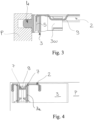
- the aforementioned fastening means 5 are introduced into the fastening seat 6 with a translational movement perpendicular to the longitudinal axis X-X of the structural member 2 (see arrow F in Figures 7-9 and 11 ).
- the aforementioned fastening means 5 of the aforementioned first end 2a of the structural member 2 are defined by a transversely projecting end flap, here projecting perpendicular to the direction in which the longitudinal axis X-X of the structural member 2 extends.
- the fastening seat 6 extends in the thickness of the anchor base 3 in a transverse direction, preferably in a perpendicular direction, relative to the direction in which the longitudinal axis X-X of the structural member 2 extends.
- the anchor base 3 may be placed on the portion P of the kitchen cabinet at different angles, for example, with the aforementioned access opening of the fastening seat 6 vertically directed so that the fastening means 5 (namely the aforementioned end flap) will be introduced with a horizontal introducing movement.
- This orientation is useful, for example, if the structural member 2 shall be used to support the kitchen cabinet hanging from a wall, since with horizontal introduction of the fastening means 5 into the fastening seat 6 the interference of the fastening means 5 against the edges of the fastening seat 6 may be utilized to provide valid support to the kitchen cabinet.
- the accessory 1 of the invention comprises special retaining/anchoring means operable to prevent such inadvertent release.
- the removable coupling relationship established between said engagement means 7 and the complementary retaining means 8 of the anchor base 3 is a removable snap fit.
- such engaging coupling relationship between said engagement means 7 and said complementary retaining means 8 opposes a predetermined load to the relative displacement of the structural member 2 away from the protrusion portion 3a of the anchor base 3 in a direction perpendicular to the longitudinal axis X-X of said structural member 2, to thereby act as safety means to keep the first end 2a of the structural member 2 engaged in the fastening seat 6 of the anchor base 3.
- the aforementioned engagement means 7 of the protrusion portion 3a of the anchor base 3 comprise opposed fastening teeth which are adapted to cooperate with each other to engage and retain the complementary retaining means 8 of the structural member 2, by opposing a predetermined load against a displacement of the structural member 2 away from the protrusion portion 3a of the anchor base 3 in a direction perpendicular to the longitudinal axis X-X of the structural member 2.
- the above fastening teeth of the protrusion portion 3a define respective and opposed undercuts 14 parallel to the longitudinal axis X-X of said structural member 2, said undercuts 14 acting as abutments to retain the complementary retaining means 8 of the structural member 2.
- the aforementioned complementary retaining means 8 of the structural member 2 remain within the thickness of the structural member 2 measured in a direction perpendicular to the longitudinal axis X-X without projecting nor jutting out from the structural member 2.
- the aforementioned complementary retaining means 8 will be substantially received or housed in a protected position within the dimensions of the structural member 2, thereby preventing the above complementary retaining means 8 from being damaged before use of the structural members 2, for example during storage or transport of these complementary elements.
- such complementary retaining means 8 of said structural member 2 comprise a sheet element 9 engaged by the engagement means 7 of the protrusion portion 3a of the anchor base 3.
- the aforementioned sheet element 9 defines a rigid element.
- the sheet element 9 may be formed as an insert element, rigidly and jointly fixed to the structural member 2.
- the aforementioned sheet element 9 is made of a metal material, although other materials may be also used such as, for example, a plastic material, possibly with reinforcing fillers to thereby provide greater strength and/or stiffness.
- the aforementioned sheet element 9 is positioned or housed at an opening 10 of said structural member 2 and the aforementioned engagement means 7 of the protrusion portion 3a of the anchor base 3 are positioned at such opening 10, to thereby avoid any interference between the anchor means 7 and the rest of the structural member 2.
- fixation means 4 for fixing the anchor base 3 to the portion P of the piece of furniture can be variously configured.
- screws, bolts, expansion bolts, socket head screws, press-fit pins or other currently known fastening systems can be variously configured.
- the aforementioned fixation means 4 for fixing the anchor base 3 to the portion P of the piece of furniture comprise at least two separate fixation pins 11 and 12 projecting out of a flat contact wall 3b.
- Such fixation pins are intended to engage corresponding receiving holes 12 formed in the portion P of the piece of furniture on which the anchor base 3 is to be fixed.
- this allows the anchor base 3 to be firmly applied to the portion P of the piece of furniture, using the specially formed holes, without using tools or other fastening elements because, as the first fixation pin 11 is introduced into its respective hole while the support base is inclined at an angle ⁇ with respect to the portion P of the piece of furniture (see Figure 13 ), a simple rotation to move the flat contact wall 3b to full contact with the portion P of the piece of furniture (see arrow R in Figure 13 ) will cause the crimping tab 11a to crimp into the side wall of its respective receiving hole and, at the same time, the second fixation pin to fit into its respective hole.
- the aforementioned structural member 2 may be embodied as a connecting cross member which axially extends between one end 2a and one end 2b opposed thereto.
- the attachment device of the present invention fulfills the aforementioned needs and also obviates prior art drawbacks as set out in the introduction of this disclosure.
- a structural member such as a connecting cross member and the like, that can be easily coupled or disengaged to/from the respective support bases fixed to the portion P of the piece of furniture, thereby providing safety means against accidental release while still allowing multiple structural members to be stacked for transport or storage, without damage to its parts.
- a further advantage of the fixation device of the present invention lies in its simplicity and structural and functional strength.
- Yet another advantage of the fastening device of the present invention is the feature of being able to take various shapes as needed, and to be applied in various modes or configurations.
Landscapes
- Engineering & Computer Science (AREA)
- General Engineering & Computer Science (AREA)
- Mechanical Engineering (AREA)
- Connection Of Plates (AREA)
- Adornments (AREA)
Claims (14)
- Möbelzubehör (1), das ein Strukturelement (2) und eine Ankerbasis (3) umfasst, wobei:- die Ankerbasis (3) dazu bestimmt ist, durch Fixierungsmittel (4) an einem Abschnitt eines Möbelstücks fixiert zu werden;- das Strukturelement (2) sich entlang einer Längsachse (X-X) zwischen gegenüberliegenden Enden erstreckt;- ein erstes Ende (2a) des Strukturelements (2) Befestigungsmittel (5) umfasst, die abnehmbar in einen Befestigungssitz (6) der Ankerbasis (3) eingeführt sind;- die Befestigungsmittel (5) mit einer Dreh- und/oder Translationskomponente senkrecht zur Längsachse (X-X) des Strukturelements (2) in den Befestigungssitz (6) eingeführt werden, so dass das Einführen der Befestigungsmittel (5) in den Befestigungssitz (6) eine starre Verbindung des Strukturelements (2) mit der Ankerbasis (3) auch bei entlang der Längsachse (X-X) gerichteten Belastungen gewährleistet und- das Strukturelement (2) einen ersten Längsabschnitt (S1) umfasst, der sich von dem ersten Ende (2a) aus erstreckt,- die Ankerbasis (3) einen Vorsprungsabschnitt (3a) umfasst, der in der Längsachse (X-X) herausragt, um dem ersten Längsabschnitt (S1) des Strukturelements (2) zugewandt zu sein und ihn zu überlappen, und- der Vorsprungsabschnitt (3a) der Ankerbasis (3) Eingriffsmittel (7) umfasst, die abnehmbar und eingreifend mit entsprechenden komplementären Rückhaltemitteln (8) gekoppelt sind, die in dem ersten Längsabschnitt (S1) des Strukturelements (2) in einer Position angeordnet sind, die von dem ersten Ende (2a) beabstandet ist,wobei die eingreifende Kupplungsbeziehung zwischen den Eingriffsmitteln (7) und den komplementären Rückhaltemitteln (8) der Verschiebung des Strukturelements (2) weg von dem Vorsprungsabschnitt (3a) der Ankerbasis (3) in einer Richtung senkrecht zur Längsachse (X-X) des Strukturelements (2) eine vorbestimmte Last entgegensetzt, um dadurch als Sicherheitsmittel zu wirken, um das erste Ende (2a) des Strukturelements (2) in dem Befestigungssitz (6) der Ankerbasis (3) in Eingriff zu halten
dadurch gekennzeichnet, dass bezüglich des Volumens des Strukturelements (2) ohne Berücksichtigung der Rückhaltemittel (8) sich ergibt, dass die komplementären Rückhaltemittel (8) des Strukturelements (2) innerhalb des Volumens enthalten sind, ohne aus dem Volumen des Strukturelements (2) in einer Richtung senkrecht zur Längsachse (X-X) herauszuragen oder vorzuspringen. - Möbelzubehör (1) nach Anspruch 1, wobei die abnehmbare Kopplungsbeziehung, die zwischen den Eingriffsmitteln (7) und den komplementären Rückhaltemitteln (8) der Ankerbasis (3) hergestellt wird, eine abnehmbare Schnappverbindung ist.
- Möbelzubehör (1) nach Anspruch 1 oder 2, wobei die Befestigungsmittel (5) des ersten Endes (2a) des Strukturelements (2) eine quer herausragende Endlasche umfassen, die vorzugsweise senkrecht zu der Richtung herausragt, in der sich die Längsachse (X-X) des Strukturelements (2) erstreckt.
- Möbelzubehör (1) nach Anspruch 1, 2 oder 3, wobei sich der Befestigungssitz (6) in der Dicke der Ankerbasis (3) in einer Querrichtung, vorzugsweise in einer senkrechten Richtung, relativ zu der Richtung erstreckt, in der sich die Längsachse (X-X) des Strukturelements (2) erstreckt.
- Möbelzubehör (1) nach einem der Ansprüche 1 bis 4, wobei die Eingriffsmittel (7) des Vorsprungsabschnitts (3a) der Ankerbasis (3) entgegengesetzte Befestigungszähne umfassen, die so ausgelegt sind, dass sie miteinander zusammenwirken, um die komplementären Rückhaltemittel (8) des Strukturelements (2) in Eingriff zu bringen und zu halten, indem sie gegen eine Verschiebung des Strukturelements (2) weg von dem Vorsprungsabschnitt (3a) der Ankerbasis (3) in einer Richtung senkrecht zur Längsachse (X-X) des Strukturelements (2) eine vorbestimmten Last entgegensetzen.
- Möbelzubehör (1) nach Anspruch 5, wobei die Befestigungszähne jeweilige und entgegengesetzte Hinterschneidungen (14) parallel zur Längsachse (X-X) des Strukturelements (2) definieren, wobei die Hinterschneidungen (14) als Widerlager wirken, um die komplementären Rückhaltemittel (8) des Strukturelements (2) zu halten.
- Möbelzubehör (1) nach einem der Ansprüche 1 bis 6, wobei die komplementären Rückhaltemittel (8) des Strukturelements (2) ein Blechelement (9) umfassen, das von den Eingriffsmitteln (7) des Vorsprungsabschnitts (3a) eingegriffen wird.
- Möbelzubehör (1) nach Anspruch 7, wobei das Blechelement (9) ein Metallblech-Brückenelement, vorzugsweise ein Brückenwerkzeug-Metallblech, definiert.
- Möbelzubehör (1) nach Anspruch 7 oder 8, wobei das Blechelement (9) ein starres Element ist, das vorzugsweise aus einem Metallmaterial besteht.
- Möbelzubehör (1) nach Anspruch 7, 8 oder 9, wobei:- das Blechelement (9) an einer Öffnung (10) des Strukturelements (2) ausgebildet, positioniert oder untergebracht ist und- die Eingriffsmittel (7) des Vorsprungsabschnitts (3a) der Ankerbasis (3) an der Öffnung (10) angeordnet sind.
- Möbelzubehör (1) nach einem der Ansprüche 1 bis 10, wobei die Fixierungsmittel (4) der Ankerbasis (3) mindestens zwei getrennte Fixierungsstifte (11,12) umfassen, die aus einer flachen Kontaktwand (3b) herausragen und dazu bestimmt sind, in entsprechende Aufnahmelöcher (12) einzugreifen, die in dem Abschnitt des Möbelstücks angeordnet sind, an dem die Ankerbasis (3) befestigt werden soll.
- Möbelzubehör (1) nach Anspruch 11, wobei:- mindestens ein erster Fixierungsstift (11) an seinem freien Ende eine Crimplasche (11a) umfasst, die so positioniert ist, dass sie in die Seitenwand eines jeweiligen Aufnahmelochs gecrimpt werden kann;- der erste Fixierungsstift (11) eine Aussparung (16) an seinem Anfangsabschnitt in der Nähe einer flachen Kontaktwand (3b) umfasst und- die Crimplasche (11a) und die Aussparung (16) winklig auf der gleichen Seite wie der erste Fixierungsstift (11) angeordnet sind,wobei die Crimplasche (11a) und die Aussparung (16) des ersten Fixierungsstifts (11) in solchen Positionen angeordnet sind, dass sie einer Endkante oder einem aufgeweiteten Endabschnitt (13) der flachen Kontaktwand (3b) zugewandt sind.
- Möbelzubehör (1) nach einem der Ansprüche 1 bis 12, wobei das Strukturelement (2) einen Verbindungsquerträger umfasst, der sich axial zwischen dem ersten Ende (2a) und einem entgegengesetzten Ende (2b) erstreckt.
- Möbelzubehör (1) nach Anspruch 13, wobei:- das zweite entgegengesetzte Ende (2b) des Verbindungsquerträgers (2) wie das erste Ende geformt ist und Befestigungsmittel (5) umfasst, die abnehmbar in einen Befestigungssitz (6) einer zweiten Ankerbasis (3) eingeführt sind, die wie die erste Ankerbasis (3) geformt ist, und- der Verbindungsquerträger (2) zusätzliche ähnliche komplementäre Rückhaltemittel (8) umfasst, die in einem zweiten Längsabschnitt (S2) des Strukturelements (2) in der Nähe des gegenüberliegenden Endes (2a) angeordnet sind und vorzugsweise durch Schnappverbindung mit den Eingriffsmitteln (7) des Vorsprungsabschnitts (3a) der zweiten Ankerbasis (3) eingreifend gekoppelt sind.
Applications Claiming Priority (1)
| Application Number | Priority Date | Filing Date | Title |
|---|---|---|---|
| IT102020000009352A IT202000009352A1 (it) | 2020-04-29 | 2020-04-29 | Accessorio per mobili |
Publications (2)
| Publication Number | Publication Date |
|---|---|
| EP3903641A1 EP3903641A1 (de) | 2021-11-03 |
| EP3903641B1 true EP3903641B1 (de) | 2025-01-29 |
Family
ID=71662192
Family Applications (1)
| Application Number | Title | Priority Date | Filing Date |
|---|---|---|---|
| EP21170294.9A Active EP3903641B1 (de) | 2020-04-29 | 2021-04-23 | Möbelzubehör |
Country Status (2)
| Country | Link |
|---|---|
| EP (1) | EP3903641B1 (de) |
| IT (1) | IT202000009352A1 (de) |
Family Cites Families (2)
| Publication number | Priority date | Publication date | Assignee | Title |
|---|---|---|---|---|
| DE7331520U (de) * | 1973-08-30 | 1974-01-24 | Henke P Kg | Verbindungsbeschlag für vornehmlich rechtwinklig aneinanderstoßende Korpusteile von zerlegbaren Möbeln |
| DE102015110561A1 (de) * | 2015-07-01 | 2017-01-05 | Form Orange Produktentwicklung | Schublade mit einer Bodenplatte, einer Blende, einer Rückwand und zwei Seitenwänden, die fest miteinander verbunden sind |
-
2020
- 2020-04-29 IT IT102020000009352A patent/IT202000009352A1/it unknown
-
2021
- 2021-04-23 EP EP21170294.9A patent/EP3903641B1/de active Active
Also Published As
| Publication number | Publication date |
|---|---|
| IT202000009352A1 (it) | 2021-10-29 |
| EP3903641A1 (de) | 2021-11-03 |
Similar Documents
| Publication | Publication Date | Title |
|---|---|---|
| KR101048732B1 (ko) | 고정 디바이스 | |
| EP1209398B1 (de) | Schnappanordnung zur lösbaren Befestigung eines Gegenstandes an mindestens einer Leitung | |
| US8132384B2 (en) | Panel and fastening system for such panel | |
| US20080237423A1 (en) | Removable shelf locking system | |
| WO2007122834A1 (ja) | 物品取付具 | |
| US7337505B1 (en) | Panel fastener | |
| US20110233950A1 (en) | Hole plug | |
| JP2013253695A (ja) | ソーラーパネル用の固定デバイス | |
| EP3587295B1 (de) | Adapterelement und transportpalette mit adapterelementen | |
| JP4235755B2 (ja) | クリップ | |
| EP2167280A1 (de) | Befestigungsmechanismus | |
| EP3903641B1 (de) | Möbelzubehör | |
| US20070194588A1 (en) | Closure element | |
| CN111237298B (zh) | 公差补偿装置 | |
| EP3778350B1 (de) | Transportsystem mit zwei transportplattformen und einem verbindungselement | |
| ES2348633T3 (es) | Herraje de enchufe. | |
| US6519816B1 (en) | Container coupling device | |
| EP2092847A1 (de) | Selbstverriegelnde gelenkverbindung für aus- und einfahrbare regale | |
| EP1557572B1 (de) | Klipp zur gegenseitigen Befestigung von zwei Teilen | |
| JP2005188623A (ja) | クリップ | |
| JP3965232B2 (ja) | 合成樹脂製パレット | |
| EP1746321A1 (de) | Befestigungseinrichtung für zylindrische Elemente, insbesondere Rohrleitungen und Kabel | |
| KR102056422B1 (ko) | 마운팅 유닛 | |
| US12414641B2 (en) | Object-hanging device | |
| EP0958186B1 (de) | Vorrichtung zur verriegelung von zwei teilen |
Legal Events
| Date | Code | Title | Description |
|---|---|---|---|
| STAA | Information on the status of an ep patent application or granted ep patent |
Free format text: STATUS: UNKNOWN |
|
| PUAI | Public reference made under article 153(3) epc to a published international application that has entered the european phase |
Free format text: ORIGINAL CODE: 0009012 |
|
| STAA | Information on the status of an ep patent application or granted ep patent |
Free format text: STATUS: THE APPLICATION HAS BEEN PUBLISHED |
|
| AK | Designated contracting states |
Kind code of ref document: A1 Designated state(s): AL AT BE BG CH CY CZ DE DK EE ES FI FR GB GR HR HU IE IS IT LI LT LU LV MC MK MT NL NO PL PT RO RS SE SI SK SM TR |
|
| B565 | Issuance of search results under rule 164(2) epc |
Effective date: 20210920 |
|
| STAA | Information on the status of an ep patent application or granted ep patent |
Free format text: STATUS: REQUEST FOR EXAMINATION WAS MADE |
|
| 17P | Request for examination filed |
Effective date: 20220502 |
|
| RBV | Designated contracting states (corrected) |
Designated state(s): AL AT BE BG CH CY CZ DE DK EE ES FI FR GB GR HR HU IE IS IT LI LT LU LV MC MK MT NL NO PL PT RO RS SE SI SK SM TR |
|
| STAA | Information on the status of an ep patent application or granted ep patent |
Free format text: STATUS: EXAMINATION IS IN PROGRESS |
|
| 17Q | First examination report despatched |
Effective date: 20230309 |
|
| RAP3 | Party data changed (applicant data changed or rights of an application transferred) |
Owner name: FORMENTI & GIOVENZANA S.P.A. |
|
| GRAP | Despatch of communication of intention to grant a patent |
Free format text: ORIGINAL CODE: EPIDOSNIGR1 |
|
| STAA | Information on the status of an ep patent application or granted ep patent |
Free format text: STATUS: GRANT OF PATENT IS INTENDED |
|
| GRAS | Grant fee paid |
Free format text: ORIGINAL CODE: EPIDOSNIGR3 |
|
| GRAA | (expected) grant |
Free format text: ORIGINAL CODE: 0009210 |
|
| STAA | Information on the status of an ep patent application or granted ep patent |
Free format text: STATUS: THE PATENT HAS BEEN GRANTED |
|
| INTG | Intention to grant announced |
Effective date: 20241127 |
|
| AK | Designated contracting states |
Kind code of ref document: B1 Designated state(s): AL AT BE BG CH CY CZ DE DK EE ES FI FR GB GR HR HU IE IS IT LI LT LU LV MC MK MT NL NO PL PT RO RS SE SI SK SM TR |
|
| REG | Reference to a national code |
Ref country code: GB Ref legal event code: FG4D |
|
| REG | Reference to a national code |
Ref country code: CH Ref legal event code: EP |
|
| REG | Reference to a national code |
Ref country code: DE Ref legal event code: R096 Ref document number: 602021025293 Country of ref document: DE |
|
| REG | Reference to a national code |
Ref country code: IE Ref legal event code: FG4D |
|
| REG | Reference to a national code |
Ref country code: NL Ref legal event code: MP Effective date: 20250129 |
|
| PG25 | Lapsed in a contracting state [announced via postgrant information from national office to epo] |
Ref country code: NL Free format text: LAPSE BECAUSE OF FAILURE TO SUBMIT A TRANSLATION OF THE DESCRIPTION OR TO PAY THE FEE WITHIN THE PRESCRIBED TIME-LIMIT Effective date: 20250129 |
|
| PG25 | Lapsed in a contracting state [announced via postgrant information from national office to epo] |
Ref country code: RS Free format text: LAPSE BECAUSE OF FAILURE TO SUBMIT A TRANSLATION OF THE DESCRIPTION OR TO PAY THE FEE WITHIN THE PRESCRIBED TIME-LIMIT Effective date: 20250429 |
|
| PG25 | Lapsed in a contracting state [announced via postgrant information from national office to epo] |
Ref country code: FI Free format text: LAPSE BECAUSE OF FAILURE TO SUBMIT A TRANSLATION OF THE DESCRIPTION OR TO PAY THE FEE WITHIN THE PRESCRIBED TIME-LIMIT Effective date: 20250129 |
|
| PG25 | Lapsed in a contracting state [announced via postgrant information from national office to epo] |
Ref country code: PL Free format text: LAPSE BECAUSE OF FAILURE TO SUBMIT A TRANSLATION OF THE DESCRIPTION OR TO PAY THE FEE WITHIN THE PRESCRIBED TIME-LIMIT Effective date: 20250129 |
|
| PGFP | Annual fee paid to national office [announced via postgrant information from national office to epo] |
Ref country code: DE Payment date: 20250428 Year of fee payment: 5 |
|
| PG25 | Lapsed in a contracting state [announced via postgrant information from national office to epo] |
Ref country code: ES Free format text: LAPSE BECAUSE OF FAILURE TO SUBMIT A TRANSLATION OF THE DESCRIPTION OR TO PAY THE FEE WITHIN THE PRESCRIBED TIME-LIMIT Effective date: 20250129 |
|
| REG | Reference to a national code |
Ref country code: LT Ref legal event code: MG9D |
|
| PG25 | Lapsed in a contracting state [announced via postgrant information from national office to epo] |
Ref country code: NO Free format text: LAPSE BECAUSE OF FAILURE TO SUBMIT A TRANSLATION OF THE DESCRIPTION OR TO PAY THE FEE WITHIN THE PRESCRIBED TIME-LIMIT Effective date: 20250429 Ref country code: IS Free format text: LAPSE BECAUSE OF FAILURE TO SUBMIT A TRANSLATION OF THE DESCRIPTION OR TO PAY THE FEE WITHIN THE PRESCRIBED TIME-LIMIT Effective date: 20250529 |
|
| PGFP | Annual fee paid to national office [announced via postgrant information from national office to epo] |
Ref country code: IT Payment date: 20250428 Year of fee payment: 5 |
|
| PG25 | Lapsed in a contracting state [announced via postgrant information from national office to epo] |
Ref country code: HR Free format text: LAPSE BECAUSE OF FAILURE TO SUBMIT A TRANSLATION OF THE DESCRIPTION OR TO PAY THE FEE WITHIN THE PRESCRIBED TIME-LIMIT Effective date: 20250129 |
|
| PG25 | Lapsed in a contracting state [announced via postgrant information from national office to epo] |
Ref country code: LV Free format text: LAPSE BECAUSE OF FAILURE TO SUBMIT A TRANSLATION OF THE DESCRIPTION OR TO PAY THE FEE WITHIN THE PRESCRIBED TIME-LIMIT Effective date: 20250129 Ref country code: PT Free format text: LAPSE BECAUSE OF FAILURE TO SUBMIT A TRANSLATION OF THE DESCRIPTION OR TO PAY THE FEE WITHIN THE PRESCRIBED TIME-LIMIT Effective date: 20250529 |
|
| PG25 | Lapsed in a contracting state [announced via postgrant information from national office to epo] |
Ref country code: GR Free format text: LAPSE BECAUSE OF FAILURE TO SUBMIT A TRANSLATION OF THE DESCRIPTION OR TO PAY THE FEE WITHIN THE PRESCRIBED TIME-LIMIT Effective date: 20250430 Ref country code: BG Free format text: LAPSE BECAUSE OF FAILURE TO SUBMIT A TRANSLATION OF THE DESCRIPTION OR TO PAY THE FEE WITHIN THE PRESCRIBED TIME-LIMIT Effective date: 20250129 |
|
| PGFP | Annual fee paid to national office [announced via postgrant information from national office to epo] |
Ref country code: AT Payment date: 20250721 Year of fee payment: 5 |
|
| PGFP | Annual fee paid to national office [announced via postgrant information from national office to epo] |
Ref country code: TR Payment date: 20250407 Year of fee payment: 5 |
|
| PG25 | Lapsed in a contracting state [announced via postgrant information from national office to epo] |
Ref country code: SE Free format text: LAPSE BECAUSE OF FAILURE TO SUBMIT A TRANSLATION OF THE DESCRIPTION OR TO PAY THE FEE WITHIN THE PRESCRIBED TIME-LIMIT Effective date: 20250129 |
|
| PG25 | Lapsed in a contracting state [announced via postgrant information from national office to epo] |
Ref country code: SM Free format text: LAPSE BECAUSE OF FAILURE TO SUBMIT A TRANSLATION OF THE DESCRIPTION OR TO PAY THE FEE WITHIN THE PRESCRIBED TIME-LIMIT Effective date: 20250129 |
|
| PG25 | Lapsed in a contracting state [announced via postgrant information from national office to epo] |
Ref country code: DK Free format text: LAPSE BECAUSE OF FAILURE TO SUBMIT A TRANSLATION OF THE DESCRIPTION OR TO PAY THE FEE WITHIN THE PRESCRIBED TIME-LIMIT Effective date: 20250129 |
|
| PG25 | Lapsed in a contracting state [announced via postgrant information from national office to epo] |
Ref country code: CZ Free format text: LAPSE BECAUSE OF FAILURE TO SUBMIT A TRANSLATION OF THE DESCRIPTION OR TO PAY THE FEE WITHIN THE PRESCRIBED TIME-LIMIT Effective date: 20250129 Ref country code: EE Free format text: LAPSE BECAUSE OF FAILURE TO SUBMIT A TRANSLATION OF THE DESCRIPTION OR TO PAY THE FEE WITHIN THE PRESCRIBED TIME-LIMIT Effective date: 20250129 |
|
| PG25 | Lapsed in a contracting state [announced via postgrant information from national office to epo] |
Ref country code: RO Free format text: LAPSE BECAUSE OF FAILURE TO SUBMIT A TRANSLATION OF THE DESCRIPTION OR TO PAY THE FEE WITHIN THE PRESCRIBED TIME-LIMIT Effective date: 20250129 |
|
| PG25 | Lapsed in a contracting state [announced via postgrant information from national office to epo] |
Ref country code: SK Free format text: LAPSE BECAUSE OF FAILURE TO SUBMIT A TRANSLATION OF THE DESCRIPTION OR TO PAY THE FEE WITHIN THE PRESCRIBED TIME-LIMIT Effective date: 20250129 |
|
| REG | Reference to a national code |
Ref country code: DE Ref legal event code: R097 Ref document number: 602021025293 Country of ref document: DE |
|
| REG | Reference to a national code |
Ref country code: CH Ref legal event code: H13 Free format text: ST27 STATUS EVENT CODE: U-0-0-H10-H13 (AS PROVIDED BY THE NATIONAL OFFICE) Effective date: 20251125 |
|
| PLBE | No opposition filed within time limit |
Free format text: ORIGINAL CODE: 0009261 |
|
| STAA | Information on the status of an ep patent application or granted ep patent |
Free format text: STATUS: NO OPPOSITION FILED WITHIN TIME LIMIT |
|
| PG25 | Lapsed in a contracting state [announced via postgrant information from national office to epo] |
Ref country code: LU Free format text: LAPSE BECAUSE OF NON-PAYMENT OF DUE FEES Effective date: 20250423 |
|
| PG25 | Lapsed in a contracting state [announced via postgrant information from national office to epo] |
Ref country code: MC Free format text: LAPSE BECAUSE OF FAILURE TO SUBMIT A TRANSLATION OF THE DESCRIPTION OR TO PAY THE FEE WITHIN THE PRESCRIBED TIME-LIMIT Effective date: 20250129 |
|
| GBPC | Gb: european patent ceased through non-payment of renewal fee |
Effective date: 20250429 |
|
| REG | Reference to a national code |
Ref country code: BE Ref legal event code: MM Effective date: 20250430 |
|
| 26N | No opposition filed |
Effective date: 20251030 |
|
| PG25 | Lapsed in a contracting state [announced via postgrant information from national office to epo] |
Ref country code: GB Free format text: LAPSE BECAUSE OF NON-PAYMENT OF DUE FEES Effective date: 20250429 |
|
| PG25 | Lapsed in a contracting state [announced via postgrant information from national office to epo] |
Ref country code: FR Free format text: LAPSE BECAUSE OF NON-PAYMENT OF DUE FEES Effective date: 20250430 |
|
| PG25 | Lapsed in a contracting state [announced via postgrant information from national office to epo] |
Ref country code: BE Free format text: LAPSE BECAUSE OF NON-PAYMENT OF DUE FEES Effective date: 20250430 |
|
| PG25 | Lapsed in a contracting state [announced via postgrant information from national office to epo] |
Ref country code: CH Free format text: LAPSE BECAUSE OF NON-PAYMENT OF DUE FEES Effective date: 20250430 |